Overview

Cisco UCS Manager Getting Started Guide Overview

This guide provides an overview of Cisco Unified Computing System (Cisco UCS) essentials, procedures for performing Cisco UCS Manager initial configuration and best practices. The following table summarizes the overall organization of the guide.

Chapter

Description

Overview

Conceptual overview of Cisco UCS architecture including Cisco Fabric Interconnects, I/O Module and key server components; Introduction to Cisco UCS Central.

System Requirements

Hardware, browser, and port requirements for Cisco UCS Manager initial configuration.

Initial Configuration

Initial Configuration workflow in the following sequence:
  1. Console Setup

  2. Configure Administration Policies

  3. Configure Equipment Policies

  4. Configure Unified Ports

  5. Configure Fabric Interconnect Server Ports

  6. Configure LAN Connectivity

  7. Configure SAN Connectivity

  8. Define Workloads

Appendix

Recommendations, best practices, configuration examples, and a glossary.

Cisco UCS Manager User Documentation

Cisco UCS Manager offers you a new set of smaller, use-case based documentation described in the following table:

Guide

Description

Cisco UCS Manager Getting Started Guide

Discusses Cisco UCS architecture and Day 0 operations, including Cisco UCS Manager initial configuration and configuration best practices.

Cisco UCS Manager Administration Guide

Discusses password management, role-based access configuration, remote authentication, communication services, CIMC session management, organizations, backup and restore, scheduling options, BIOS tokens, and deferred deployments.

Cisco UCS Manager Infrastructure Management Guide

Discusses physical and virtual infrastructure components used and managed by Cisco UCS Manager.

Cisco UCS Manager Firmware Management Guide

Discusses downloading and managing firmware, upgrading through Auto Install, upgrading through service profiles, directly upgrading at endpoints using firmware auto sync, managing the capability catalog, deployment scenarios, and troubleshooting.

Cisco UCS Manager Server Management Guide

Discusses the new licenses, registering Cisco UCS domain with Cisco UCS Central, power capping, server boot, server profiles, and server-related policies.

Cisco UCS Manager Storage Management Guide

Discusses all aspects of storage management, such as SAN and VSAN in Cisco UCS Manager.

Cisco UCS Manager Network Management Guide

Discusses all aspects of network management, such as LAN and VLAN connectivity in Cisco UCS Manager.

Cisco UCS Manager System Monitoring Guide

Discusses all aspects of system and health monitoring, including system statistics in Cisco UCS Manager.

Cisco UCS S3260 Server Integration with Cisco UCS Manager

Discusses all aspects of management of UCS S-Series servers that are managed through Cisco UCS Manager.

Fundamentals of Cisco Unified Computing System

Cisco Unified Computing System Overview

Cisco UCS has a unique architecture that integrates compute, data network access, and storage network access into a common set of components under a single-pane-of-glass management interface.

Cisco UCS fuses access layer networking and servers. This high-performance, next-generation server system provides a data center with a high degree of workload agility and scalability. The hardware and software components support Cisco's unified fabric, which runs multiple types of data center traffic over a single converged network adapter.

Figure 1. Cisco Unified Computing System Architecture

Architectural Simplification

The simplified architecture of Cisco UCS reduces the number of required devices and centralizes switching resources. By eliminating switching inside a chassis, network access-layer fragmentation is significantly reduced. Cisco UCS implements Cisco unified fabric within racks and groups of racks, supporting Ethernet and Fibre Channel protocols over 10/25/40 Gigabit Cisco Data Center Ethernet and Fibre Channel over Ethernet (FCoE) links. This radical simplification reduces the number of switches, cables, adapters, and management points by up to two-thirds. All devices in a Cisco UCS domain remain under a single management domain, which remains highly available through the use of redundant components.

High Availability

The management and data plane of Cisco UCS is designed for high availability and redundant access layer fabric interconnects. In addition, Cisco UCS supports existing high availability and disaster recovery solutions for the data center, such as data replication and application-level clustering technologies.

Scalability

A single Cisco UCS domain supports multiple chassis and their servers, all of which are administered through one Cisco UCS Manager. For more detailed information about the scalability, speak to your Cisco representative.

Flexibility

A Cisco UCS domain allows you to quickly align computing resources in the data center with rapidly changing business requirements. This built-in flexibility is determined by whether you choose to fully implement the stateless computing feature. Pools of servers and other system resources can be applied as necessary to respond to workload fluctuations, support new applications, scale existing software and business services, and accommodate both scheduled and unscheduled downtime. Server identity can be abstracted into a mobile service profile that can be moved from server to server with minimal downtime and no need for additional network configuration.

With this level of flexibility, you can quickly and easily scale server capacity without having to change the server identity or reconfigure the server, LAN, or SAN. During a maintenance window, you can quickly do the following:

  • Deploy new servers to meet unexpected workload demand and rebalance resources and traffic.

  • Shut down an application, such as a database management system, on one server and then boot it up again on another server with increased I/O capacity and memory resources.

Optimized for Server Virtualization

Cisco UCS has been optimized to implement VM-FEX technology. This technology provides improved support for server virtualization, including better policy-based configuration and security, conformance with a company's operational model, and accommodation for VMware's VMotion.

IOMs and Fabric Interconnects Connectivity

Each chassis is equipped with two IOMs: IOM 1 should be connected to Fabric Interconnect A. IOM 2 should be connected to Fabric Interconnect B. This configuration provides redundant paths, ensuring uninterrupted operation of the Cisco UCS system even in the event of a failure in one of the Fabric Interconnects or IOMs. Additionally, this configuration enables traffic load distribution across both Fabric Interconnects, enhancing load balancing and increasing throughput. As a result, the Cisco UCS system achieves high availability, reliability, and optimal performance, making it ideal for data center environments.

Uplink Connectivity

Use fabric interconnect ports configured as uplink ports to connect to uplink upstream network switches. Connect these uplink ports to upstream switch ports as individual links, or as links configured as port channels. Port channel configurations provide bandwidth aggregation as well as link redundancy.

You can achieve northbound connectivity from the fabric interconnect through a standard uplink, a port channel, or a virtual port channel configuration. The port channel name and ID configured on fabric interconnect should match the name and ID configuration on the upstream Ethernet switch.

It is also possible to configure a port channel as a vPC, where port channel uplink ports from a fabric interconnect are connected to different upstream switches. After all uplink ports are configured, create a port channel for these ports.

Downlink Connectivity

Each fabric interconnect is connected to IOMs in the UCS chassis, which provides connectivity to each blade server. Internal connectivity from blade servers to IOMs is transparently provided by Cisco UCS Manager using 10BASE-KR Ethernet standard for backplane implementations, and no additional configuration is required. You must configure the connectivity between the fabric interconnect server ports and IOMs. Each IOM, when connected with the fabric interconnect server port, behaves as a line card to fabric interconnect, hence IOMs should never be cross-connected to the fabric interconnect. Each IOM is connected directly to a single fabric interconnect.

The Fabric Extender (also referred to as the IOM, or FEX) logically extends the fabric interconnects to the blade server. The best analogy is to think of it as a remote line card that’s embedded in the blade server chassis, allowing connectivity to the external world. IOM settings are pushed via Cisco UCS Manager and are not managed directly. The primary functions of this module are to facilitate blade server I/O connectivity (internal and external), multiplex all I/O traffic up to the fabric interconnects, and help monitor and manage the Cisco UCS infrastructure.

Configure Fabric interconnect ports that should be connected to downlink IOM cards as server ports. Make sure there is physical connectivity between the fabric interconnect and IOMs. You must also configure the IOM ports and the global chassis discovery policy.


Note


For UCS 2200 I/O modules, you can also select the Port Channel option and all I/O module-connected server ports will be automatically added to a port channel.


Unified Fabric

With unified fabric, multiple types of data center traffic can run over a single Data Center Ethernet (DCE) network. Instead of having a series of different host bus adapters (HBAs) and network interface cards (NICs) present in a server, unified fabric uses a single converged network adapter. This type of adapter can carry LAN and SAN traffic on the same cable.

Cisco UCS uses Fibre Channel over Ethernet (FCoE) to carry Fibre Channel and Ethernet traffic on the same physical Ethernet connection between the fabric interconnect and the server. This connection terminates at a converged network adapter on the server, and the unified fabric terminates on the uplink ports of the fabric interconnect. On the core network, the LAN and SAN traffic remains separated. Cisco UCS does not require that you implement unified fabric across the data center.

The converged network adapter presents an Ethernet interface and Fibre Channel interface to the operating system. At the server, the operating system is not aware of the FCoE encapsulation because it sees a standard Fibre Channel HBA.

At the fabric interconnect, the server-facing Ethernet port receives the Ethernet and Fibre Channel traffic. The fabric interconnect (using Ethertype to differentiate the frames) separates the two traffic types. Ethernet frames and Fibre Channel frames are switched to their respective uplink interfaces.

Fibre Channel over Ethernet

Cisco UCS leverages Fibre Channel over Ethernet (FCoE) standard protocol to deliver Fibre Channel. The upper Fibre Channel layers are unchanged, so the Fibre Channel operational model is maintained. FCoE network management and configuration is similar to a native Fibre Channel network.

FCoE encapsulates Fibre Channel traffic over a physical Ethernet link. FCoE is encapsulated over Ethernet with the use of a dedicated Ethertype, 0x8906, so that FCoE traffic and standard Ethernet traffic can be carried on the same link. FCoE has been standardized by the ANSI T11 Standards Committee.

Fibre Channel traffic requires a lossless transport layer. Instead of the buffer-to-buffer credit system used by native Fibre Channel, FCoE depends upon the Ethernet link to implement lossless service.

Ethernet links on the fabric interconnect provide two mechanisms to ensure lossless transport for FCoE traffic:

  • Link-level flow control

  • Priority flow control

Link-Level Flow Control

IEEE 802.3x link-level flow control allows a congested receiver to signal the endpoint to pause data transmission for a short time. This link-level flow control pauses all traffic on the link.

The transmit and receive directions are separately configurable. By default, link-level flow control is disabled for both directions.

On each Ethernet interface, the fabric interconnect can enable either priority flow control or link-level flow control (but not both).

When an interface on a or Cisco UCS 6400 Series Fabric Interconnect has Priority Flow Control (PFC) admin configured as auto and Link-Level Flow Control (LLFC) admin configured as on, the PFC operation mode will be off and the LLFC operation mode will be on. On UCS 6300 Series and earlier Fabric Interconnects, the same configuration will result in the PFC operation mode being on and the LLFC operation mode being off.

Priority Flow Control

The priority flow control (PFC) feature applies pause functionality to specific classes of traffic on the Ethernet link. For example, PFC can provide lossless service for the FCoE traffic, and best-effort service for the standard Ethernet traffic. PFC can provide different levels of service to specific classes of Ethernet traffic (using IEEE 802.1p traffic classes).

PFC decides whether to apply pause based on the IEEE 802.1p CoS value. When the fabric interconnect enables PFC, it configures the connected adapter to apply the pause functionality to packets with specific CoS values.

By default, the fabric interconnect negotiates to enable the PFC capability. If the negotiation succeeds, PFC is enabled and link-level flow control remains disabled (regardless of its configuration settings). If the PFC negotiation fails, you can either force PFC to be enabled on the interface or you can enable IEEE 802.x link-level flow control.

Cisco UCS Building Blocks and Connectivity

Figure 2. Cisco UCS Building Blocks and Connectivity


As shown in the figure above, the primary components included within Cisco UCS are as follows:

  • Cisco UCS Manager—Cisco UCS Manager is the centralized management interface for Cisco UCS. For more information on Cisco UCS Manager, see Introduction to Cisco UCS Manager in Cisco UCS Manager Getting Started Guide

  • Cisco UCS Fabric Interconnects—The Cisco UCS Fabric Interconnect is the core component of Cisco UCS deployments, providing both network connectivity and management capabilities for the Cisco UCS system. The Cisco UCS Fabric Interconnects run the Cisco UCS Manager control software and consist of the following components:

    • Cisco UCS fabric interconnects:

      • Cisco UCS 6536 Fabric Interconnect

      • Cisco UCS 6400 Series Fabric Interconnect

      • Cisco UCS 6332 Series Fabric Interconnects

      • Cisco UCS-FI-6324 (Cisco UCS Mini)

    • Transceivers for network and storage connectivity

    • Expansion modules for various Fabric Interconnects

    • Cisco UCS Manager software

    For more information on Cisco UCS Fabric Interconnects, see Cisco UCS Fabric Infrastructure Portfolio.

  • Cisco UCS I/O Modules and Cisco UCS Fabric Extender—IO modules are also known as Cisco FEX or simply FEX modules. These modules serve as line cards to the FIs in the same way that Cisco Nexus Series switches can have remote line cards. IO modules also provide interface connections to blade servers. They multiplex data from blade servers and provide this data to FIs and do the same in the reverse direction. In production environments, IO modules are always used in pairs to provide redundancy and failover.


    Important


    The 40G backplane setting is not applicable for 22xx IOMs.


  • Cisco UCS Blade Server Chassis—The Cisco UCS 5100 Series Blade Server Chassis is a crucial building block of Cisco UCS, delivering a scalable and flexible architecture for current and future data center needs, while helping reduce total cost of ownership.

  • Cisco UCS Blade and Rack Servers—Cisco UCS Blade servers are at the heart of the UCS solution. They come in various system resource configurations in terms of CPU, memory, and hard disk capacity. The Cisco UCS rack-mount servers are standalone servers that can be installed and controlled individually. Cisco provides Fabric Extenders (FEXs) for the rack-mount servers. FEXs can be used to connect and manage rack-mount servers from FIs. Rack-mount servers can also be directly attached to the fabric interconnect.

    Small and Medium Businesses (SMBs) can choose from different blade configurations as per business needs.

  • Cisco UCS I/O Adapters—Cisco UCS B-Series Blade Servers are designed to support up to two network adapters. This design can reduce the number of adapters, cables, and access-layer switches by as much as half because it eliminates the need for multiple parallel infrastructure for both LAN and SAN at the server, chassis, and rack levels.

Cisco UCS Fabric Infrastructure Portfolio

The Cisco UCS fabric interconnects are top-of-rack devices and provide unified access to the Cisco UCS domain. The following fabric interconnects are available in the Cisco UCS fabric interconnects product family:

  • Cisco UCS Manager Release 4.2(3b) introduces Cisco UCS 6536 Fabric Interconnect to the Cisco UCS 6500 Series Fabric Interconnects.

  • Cisco UCS Manager Release 4.1 introduces the Cisco UCS 64108 Fabric Interconnect to the Cisco UCS 6400 Series Fabric Interconnects.

  • Cisco UCS 6300 Series Fabric Interconnects

  • Cisco UCS 6324 Fabric Interconnects

  • Cisco UCS 6200 Series Fabric Interconnects


Note


The Cisco UCS 6200 Series, Cisco UCS 6100 Series Fabric Interconnects, and Cisco UCS 2104 I/O Modules have reached end of life.


Expansion Modules

The Cisco UCS 6200 Series supports expansion modules that can be used to increase the number of 10G, FCoE, and Fibre Channel ports.

  • The Cisco UCS 6248 UP has 32 ports on the base system. It can be upgraded with one expansion module providing an additional 16 ports.

  • The Cisco UCS 6296 UP has 48 ports on the base system. It can be upgraded with three expansion modules providing an additional 48 ports.

Cisco UCS Manager Fabric Interconnects

Cisco UCS 6400 Series Fabric Interconnect Overview

Cisco UCS 6400 Series Fabric Interconnect provides both network connectivity and management capabilities to the Cisco UCS system. The fabric interconnect provides Ethernet and Fibre Channel to the servers in the system, the servers connect to the fabric interconnect, and then to the LAN or SAN.

Each Cisco UCS 6400 Series Fabric Interconnect runs Cisco UCS Manager to fully manage all Cisco UCS elements. The fabric interconnect supports 10/25 Gigabit ports in the fabric with 40/100 Gigabit uplink ports. High availability can be achieved when a Cisco UCS 6400 Series Fabric Interconnect is connected to another Cisco UCS 6400 Series Fabric Interconnect through the L1 or L2 port on each device.

Cisco UCS 6400 Series Fabric Interconnect consists of:

  • Cisco UCS 6454 Fabric Interconnects

  • Cisco UCS 64108 Fabric Interconnects

Cisco UCS 6536 Fabric Interconnect

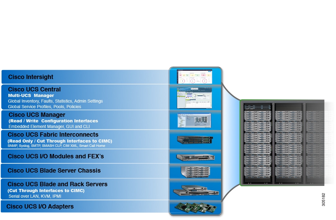
The Cisco UCS 6536 Fabric Interconnect (UCSC-FI-6536) is a One-rack unit (1RU), top of rack (TOR), fixed-port data center platform that provides both network connectivity and management capabilities to the Cisco UCS system.

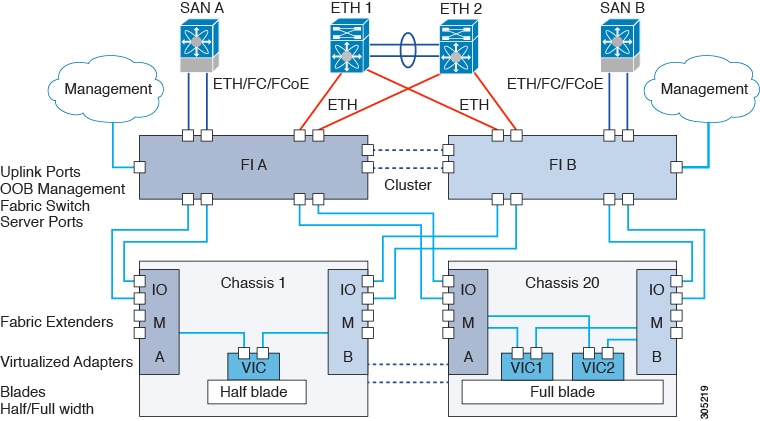
The fabric interconnect can provide Ethernet and Fibre Channel connectivity to the servers in the system. The servers connect to the fabric interconnect, and then to the LAN or SAN.

High availability and redundancy can be achieved by connecting a pair of fabric interconnects to each other through L1 or L2 ports in cluster mode configuration.

Each Cisco UCS 6536 Fabric Interconnect offers the following features:

  • Thirty-six QSFP28 ports capable of 100G including 4 unified ports (33-36). Ports also support:

    • Autonegotiating with peer devices to speeds of 100G, 40G, 25G, 10G, and 1G.

    • Port breakout is supported for Ethernet ports (1-32) and Unified ports (33-36).

      • Ethernet breakout is supported on switch ports 1 through 36 when each port is configured with a breakout cable.

        • The Dynamic Ethernet Breakout feature enables converting a standard Ethernet port to a breakout port on-the-fly so that you do not need to reboot the Fabric Interconnect. Dynamic Ethernet Breakout also supports converting breakout ports back to a standard Ethernet port without a reboot.

      • FC breakout is supported on ports 33 through 36 wherein each port is configured with a four-port breakout cable. For example 1/33/1, 1/33/2, 1/33/3, and 1/33/4 are the four FC breakout ports on the physical port 33.


        Note


        Fibre Channel support is only available through the configuration of Unified Ports (33-36) as FC breakout port.


        • FC breakout ports support peer communication at fixed speeds of 8Gbs, 16 Gbps, and 32 Gbps.

        • All four FC breakout ports must be configured with the same speed. Mixed speeds on a QSFP port's FC breakout ports are not supported.

        • Using breakout ports enables the fabric interconnect to support the maximum 16 FC ports supported by Fibre Channel.


      Note


      • Converting from Ethernet to FC breakout ports, or FC breakout ports back to Ethernet, requires a reboot/reload after changing the breakout type.

      • FCoE storage ports are not supported.


  • One management port (one 10/100/1000BASE-T port)

  • Two L1/L2 Ethernet RJ-45 ports for high availability or cluster configurations. Ethernet ports support 10/100/1000Mb speed.

  • One console port (RS-232)

  • One USB 3.0 port

  • CPU: 4 Core, 1.8GHz, Intel 5th-Generation core processor

  • Memory:

    • 32 GB DDR4 DIMMs

    • 128 GB M.2 SSD Flash Drive

    • 32 GB Boot Flash (16 MB primary, and 16 MB standby/golden)

This fabric interconnect includes the following user-replaceable components:

  • Fan modules (6), each is a port-side exhaust fan module with dark grey latch coloring (UCS-FAN-6536).

  • Power supply modules (2). One power supply module (PSU) is the active module for operations, and the second PSU is the standby for redundancy [1+1]) with the following choices:

    • 1100-W AC power supply with dark grey latch coloring (UCS-PSU-6536-AC)


    Note


    All fan modules and power supplies must use the same airflow direction.


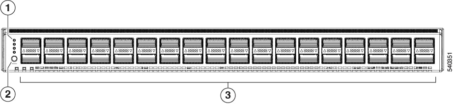
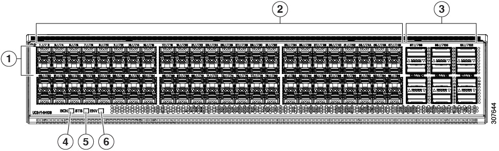
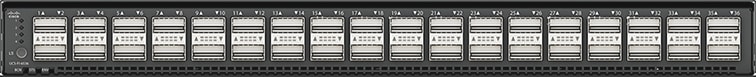
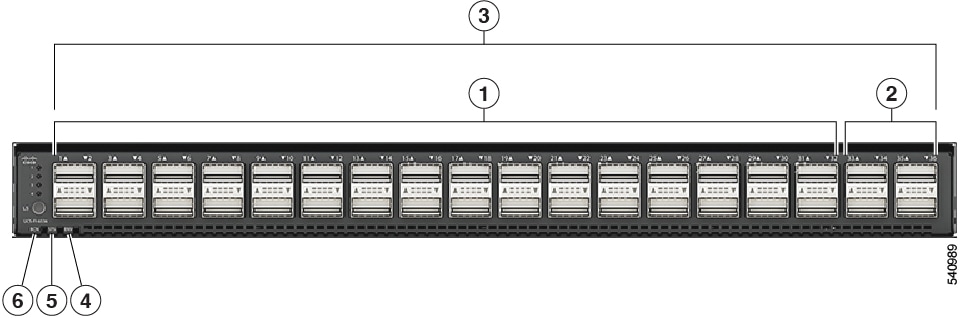
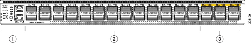
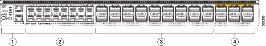
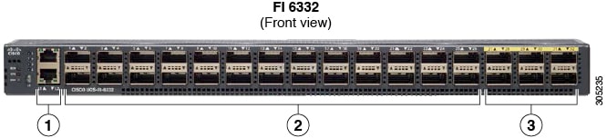
The following figure shows the fabric interconnect features on the port side of the chassis.

1

LEDs

3

36 40/100-Gigabit QSFP28 ports

2

Lane Select button

To determine which transceivers, adapters, and cables are support the fabric interconnect, see the Cisco Transceiver Modules Compatibility Information document.

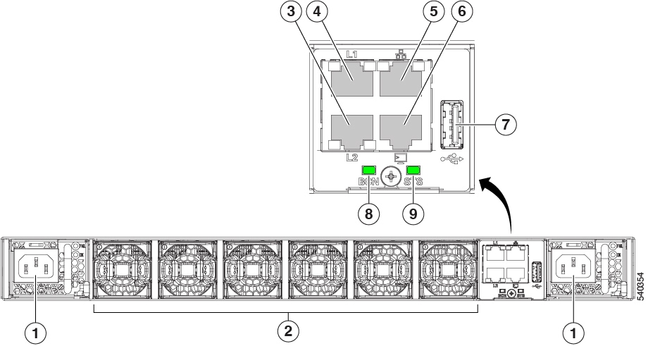
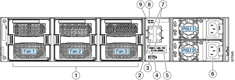
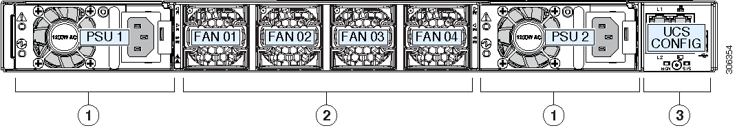
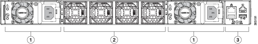
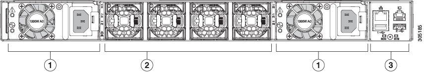
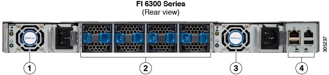
The following figure shows the fabric interconnect features on the power supply side of the chassis.

1

Power supply modules (1 or 2) (AC power supplies shown) with slots numbered 1 (left) and 2 (right).

2

Fan modules (6) with slots numbered from 1 (left) to 6 (right).

3

Layer 2 (L2) Ethernet port, 10/100/100Mb autonegotiating.

Supports high availability (HA) or clustering through an RJ-45 port.

4

Layer 1 (L1) Ethernet port, 10/100/100Mb autonegotiating.

Supports high availability (HA) or clustering through an RJ-45 port.

5

Ethernet network management port (RJ45), 10/100/1000Mb autonegotiating

6

Serial Console port (RJ45), 9600 baud.

7

USB 3.0/2.0 port

Supports booting the system and downloading scripts.

8

Beacon (BCN) LED

9

Status (STS) LED

-

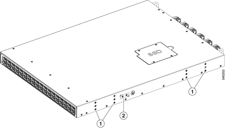
The following figure shows the side of the chassis.

1

Screw holes for mounting brackets

2

Grounding pad

Plan to position the ports in a hot aisle so that fans and power supplies intake air from the cold aisle, blow the cool air through the fabric interconnect, and exhaust the heated air into the hot aisle.

The fan and power supply modules are field replaceable. You can replace one fan module or one power supply module during operations so long as the other modules are installed and operating. If you have only one power supply installed, you can install the replacement power supply in the open slot before removing the original power supply.


Note


All fan and power supply modules must have the same direction of airflow. Otherwise, the fabric interconnect can overheat and shut down.


Caution


Because fans and power supply modules have port-side exhaust airflow (blue coloring for fan modules), you must locate the ports in the hot aisle. If you locate the air intake in a hot aisle, the fabric interconnect can overheat and shut down.


Cisco UCS 64108 Fabric Interconnect

The Cisco UCS 64108 Fabric Interconnect is a 2 RU top-of-rack (TOR) switch that mounts in a standard 19-inch rack such as the Cisco R Series rack. This high-density FI is an ideal upgrade from the high-density Cisco UCS 6296 Fabric Interconnect.

The high-density Cisco UCS 64108 Fabric Interconnect has 96 10/25 Gb SFP28 ports and 12 40/100 Gb QSFP28 ports. Each 40/100 Gb port can break out into 4 x 10/25 Gb uplink ports. Ports 1 - 16 are unified ports that support 10/25 GbE or 8/16/32G Fibre Channel speeds. Ports 89-96 support 1Gbps Ethernet speeds.

The Cisco UCS 64108 Fabric Interconnect supports either:

  • Eight FCoE port channels

  • Or Four SAN port channels

  • or Four SAN port channels and four FCoE port channels

The Cisco UCS 64108 Fabric Interconnect also has one network management port, one RS-232 serial console port for setting the initial configuration, and one USB port for saving or loading configurations. The FI also includes L1/L2 ports for connecting two fabric interconnects in a high-availability configuration.

The Cisco UCS 64108 Fabric Interconnect also contains a CPU board that consists of:

  • Intel Xeon Processor, 6 core

  • 64 GB of RAM

  • 8 MB of NVRAM (4 x NVRAM chips)

  • 128 GB SSD (bootflash)

Figure 3. Cisco UCS 64108 Fabric Interconnect Rear View

1

Ports 1-16

Unified ports:

  • 10/25 Gbps Ethernet or FCoE

  • 8/16/32 Gbps Fibre Channel

2

Ports 17-88

(10/25 Gbps Ethernet or FCoE)

3

Ports 89-96

  • 10/25 Gbps Ethernet or FCoE

  • 1 Gbps Ethernet

4

Uplink Ports 97-108 (40/100 Gbps Ethernet or FCoE)

Each of these ports can be 4 x 10/25 Gbps Ethernet or FCoE uplink ports when using a breakout cable.

5

System environment (fan fault) LED

6

System status LED

7

Beacon LED

The Cisco UCS 64108 Fabric Interconnect has two power supplies (redundant as 1+1) and three fans (redundant as 2+1).

Figure 4. Cisco UCS 64108 Fabric Interconnect Front View

1

Cooling fans

(hot swappable, 2+1 redundancy)

2

RS-232 serial console port (RJ-45 connector)

3

Network management port (RJ-45 connector)

4

USB port

5

Grounding pad for two-hole grounding lug (under protective label)

6

Power supplies

Two identical AC or DC PSUs, hot-swappable, 1+1 redundancy)

7

L1/L2 high-availability ports (RJ-45 connector)

8

Beacon LED

9

System status LED

Cisco UCS 6454 Fabric Interconnect

The Cisco UCS 6454 Fabric Interconnect (FI) is a 1-RU top-of-rack switch that mounts in a standard 19-inch rack such as the Cisco R Series rack.

The Cisco UCS 6454 Fabric Interconnect has 48 10/25 Gb SFP28 ports (16 unified ports) and 6 40/100 Gb QSFP28 ports. Each 40/100 Gb port can break out into 4 x 10/25 Gb uplink ports. The sixteen unified ports support 10/25 GbE or 8/16/32G Fibre Channel speeds.


Note


The Cisco UCS 6454 Fabric Interconnect supported 8 unified ports (ports 1 - 8) with Cisco UCS Manager 4.0(1) and 4.0(2), but with release 4.0(4) and later it supports 16 unified ports (ports 1 - 16).


The Cisco UCS 6454 Fabric Interconnect supports:

  • Maximum of 8 FCoE port channels

  • Or 4 SAN port channels

  • Or a maximum of 8 SAN port channels and FCoE port channels (4 each)

The Cisco UCS 6454 Fabric Interconnect also has one network management port, one console port for setting the initial configuration, and one USB port for saving or loading configurations. The FI also includes L1/L2 ports for connecting two fabric interconnects for high availability.

The Cisco UCS 6454 Fabric Interconnect also contains a CPU board that consists of:

  • Intel Xeon D-1528 v4 Processor, 1.6 GHz

  • 64 GB of RAM

  • 8 MB of NVRAM (4 x NVRAM chips)

  • 128 GB SSD (bootflash)

Figure 5. Cisco UCS 6454 Fabric Interconnect Rear View

1

Ports 1-16 (Unified Ports 10/25 Gbps Ethernet or FCoE or 8/16/32 Gbps Fibre Channel)

Note


When using Cisco UCS Manager releases earlier than 4.0(4), only ports 1-8 are Unified Ports.

2

Ports 17-44 (10/25 Gbps Ethernet or FCoE)

Note


When using Cisco UCS Manager releases earlier than 4.0(4), ports 9-44 are 10/25 Gbps Ethernet or FCoE.

3

Ports 45-48 (1/10/25 Gbps Ethernet or FCoE)

4

Uplink Ports 49-54 (40/100 Gbps Ethernet or FCoE)

Each of these ports can be 4 x 10/25 Gbps Ethernet or FCoE uplink ports when using an appropriate breakout cable.

The Cisco UCS 6454 Fabric Interconnect chassis has two power supplies and four fans. Two of the fans provide front to rear airflow.

Figure 6. Cisco UCS 6454 Fabric Interconnect Front View

1

Power supply and power cord connector

2

Fans 1 through 4, numbered left to right, when facing the front of the chassis.

3

L1 port, L2 port, RJ45, console, USB port, and LEDs

Ports on the Cisco UCS Fabric Interconnects


Note


Migration of any previous generation Fabric Interconnects to the Cisco UCS 9108 100G Intelligent Fabric Module is currently not supported.


Ports on the Cisco UCS 6536 Fabric Interconnects can be configured to carry either Ethernet or Fibre Channel traffic. You can configure only ports 33-36 to carry Fibre Channel traffic. The ports cannot be used by a Cisco UCS domain until you configure them.

Ports on the Cisco UCS 6400 Series Fabric Interconnects can be configured to carry either Ethernet or Fibre Channel traffic. You can configure only ports 1-16 to carry Fibre Channel traffic. The ports cannot be used by a Cisco UCS domain until you configure them.


Note


  • The Cisco UCS 6454 Fabric Interconnect supported 8 unified ports (ports 1 - 8) with Cisco UCS Manager 4.0(1) and 4.0(2), but with Release 4.0(4) and later releases, it supports 16 unified ports (ports 1 - 16).

    When you configure a port on a Fabric Interconnect, the administrative state is automatically set to enabled. If the port is connected to another device, this may cause traffic disruption. The port can be disabled and enabled after it has been configured.


The following table summarizes the port support for second, third, fourth, fifth generation of Cisco UCS Fabric Interconnects

Second Generation

Third Generation

Fourth Generation

Fifth Generation

Item

Cisco UCS 6248 UP

Cisco UCS 6296 UP

Cisco UCS 6332

Cisco UCS 6332-16UP

Cisco UCS 6454

Cisco UCS 64108

Cisco UCS 6536

Description

48-Port Fabric Interconnect

96-Port Fabric Interconnect

32-Port Fabric Interconnect

40-Port Fabric Interconnect

54-Port Fabric Interconnect

108-Port Fabric Interconnect

36-Port Fabric Interconnect

Form factor

1 RU

2 RU

1 RU

1 RU

1 RU

2 RU

1 RU

Number of fixed 10 GB Interfaces

32

48

96 (40G to 4 x 10G breakout cables), QSA, Port 13 and 14 do not support 40G to 10G breakout

88 (40G to 4 x 10G breakout cables)

48 10G/25G interfaces

96 10G/25G interfaces

36 10G/25G/40G/100G interfaces

Note


144 breakout ports (36x4)

Number of Unified Ports

32

48

16

16

This FI supported 8 unified ports (ports 1 - 8) with Cisco UCS Manager 4.0(1) and 4.0(2), but with Release 4.0(4) and later it supports 16 unified ports (ports 1 - 16).

16

ports 1-16

4

Note


16 breakout ports (4x4)

Unified Port Speeds in Gbps

1G/10G or 1G/2G/4G/8G-FC

1G/10G or 1G/2G/4G/8G-FC

1G/10G or 4G/8G/16G-FC

10G/25G or 8G/16G/32G-FC

10G/25G or 8G/16G/32G-FC

10G/25G/40G/100G FC

Number of 40-Gbps ports

32

24

6 40G/100G

12 40G/100G

36

Unified Port Range

Ports 1-32

Ports 1-48

None

Ports 1-16

Ports 1-16

Ports 1-16

Ports 33-36

Compatibility with the IOM

UCS 2204, UCS 2208

UCS 2204, UCS 2208

UCS 2204, UCS 2208, UCS 2304, UCS 2304V2

UCS 2204, UCS 2208, UCS 2304, UCS 2304V2

UCS 2204, UCS 2208, UCS 2408

UCS 2204, UCS 2208, UCS 2408

UCS 2408, UCS 2304, UCS 2304V2

Compatibility with the FEX

Cisco Nexus 2232PP

Cisco Nexus 2232TM-E

Cisco Nexus 2232PP

Cisco Nexus 2232TM-E

Cisco Nexus 2232PP

Cisco Nexus 2232TM-E

Cisco Nexus 2348UPQ

Cisco Nexus 2232PP

Cisco Nexus 2232TM-E

Cisco Nexus 2348UPQ

Cisco Nexus 2232PP

Cisco Nexus 2232TM-E

Cisco Nexus 93180YC-FX3

Cisco Nexus 2232PP

Cisco Nexus 2232TM-E

Cisco Nexus 93180YC-FX3

Cisco Nexus 93180YC-FX3

N2K-C2348UPQ

Expansion Slots

1 (16 port)

3 (16 port)

None

None

None

None

None

Fan Modules

2

4

4

4

4

3

6

Power Supplies

2 (AC/DC available)

2 (AC/DC available)

2 (AC/DC)

2 (AC/DC)

2 (AC/DC)

2 (AC/DC)

2 (AC)

Port Breakout Functionality on Cisco UCS 6536 Fabric Interconnects

The Cisco UCS 6536 36-Port Fabric Interconnect is a One-Rack-Unit (1RU) 1/10/25/40/100 Gigabit Ethernet, FCoE, and Fibre Channel switch offering up to 7.42 Tbps throughput and up to 36 ports.

Cisco UCS 6536 Fabric Interconnect supports splitting a single 40 Gigabit(G)/100G Quad Small Form-factor Pluggable (QSFP) port into four 10G/25G ports using a supported breakout cable. The switch has 32 40/100-Gbps Ethernet ports and four unified ports that can support 40/100-Gbps Ethernet ports or 16 Fiber Channel (FC) ports after breakout at 8/16/32-Gbps FC speeds. The 16 FC ports after breakout can operate as an FC Uplink or FC storage port. The switch also supports two ports (Port 9 and Port 10) at 1-Gbps speed using QSA, and all 36 ports can breakout for 10 or 25 Gbps Ethernet connectivity. All Ethernet ports can support FCoE.

Port breakout is supported for Ethernet ports (1-32) and Unified ports (33-36). These 40/100G ports are numbered in a 2-tuple naming convention. The process of changing the configuration from 40G to 10G, or from 100G to 25G is called breakout, and the process of changing the configuration from [4X]10G to 40G or from [4X]25G to 100G is called unconfigure.

When you break out a 40G port into 10G ports or a 100G port into 25G ports, the resulting ports are numbered using a 3-tuple naming convention. For example, the breakout ports of the second 40-Gigabit Ethernet port are numbered as 1/31/1, 1/31/2, 1/31/3, and 1/31/4.

FC breakout is supported on ports 36 through 33 when each port is configured with a four-port breakout cable. For example: Four FC breakout ports on the physical port 33 are numbered as 1/33/1, 1/33/2, 1/33/3, and 1/33/4.


Note


Fibre Channel support is only available through the configuration of the Unified Ports (36-33) as Fibre Channel breakout port.


The following image shows the rear view of the Cisco UCS 6536 fabric interconnect:

Figure 7. Cisco UCS 6536 Fabric Interconnect Rear View

The following image shows the rear view of the Cisco UCS 6536 fabric interconnect that include Ports and LEDs:

Figure 8. Cisco UCS 6536 Fabric Interconnect Rear View

1

Ports 1-32.

Uplink ports are Ethernet port that can operate with the port speed of 10 Gbps/25 Gbps/40 Gbps/100 Gbps.

When using a breakout cable, each of these ports can operate as: 4 x 10 Gbps/4x 25 Gbps/1 x 40 Gbps/1 x 100 Gbps Ethernet or FCoE ports.

2

Ports 33-36.

Unified Ports can operate with port speed of 10 Gbps/25 Gbps/ 40 Gbps/100 Gbps Ethernet.

or

8 Gbps/16 Gbps/32 Gbps Fibre Channel (FC).

When using a breakout cable, each of these ports can operate as 4 x 10 Gbps/4 x 25 Gbps Ethernet or 4x8Gbps/4x16Gbps/4x32Gbps FC ports.

3

Ports 1-36.

Uplink ports and Unified ports that can be configured as Ethernet Breakout Port and can operate with the port speed of 10 Gbps/25 Gbps/40 Gbps/100 Gbps.

When using a breakout cable, each of these ports can operate as: 4 x 10 Gbps/4x 25 Gbps/1 x 40 Gbps/1 x 100 Gbps Ethernet or FCoE ports.

4

System environment (fan fault) LED

5

System status (STS) LED

6

Beacon (BCN) LED

Breakout Port Guidelines

The following are the guidelines for breakout functionality for Cisco UCS 6536 Fabric Interconnects:

  • The configurable breakout ports are from port 1-36.

  • You can configure the speed for each breakout port. Each breakout port can be configured at the speed of 4 x 8 Gbps/ 4 x 16 Gbps/ 4 x 32 Gbps for Fibre Channel.

    • For Fibre Channel breakout, each breakout port can be configured at the speed of 4 x 8 Gbps/ 4 x 16 Gbps/ 4 x 32 Gbps.

    • For Ethernet breakout, each breakout port can be configured at the speed of 4 x 10 Gbps/4 x 25 Gbps.

  • Fibre Channel breakout ports are supported, and Fiber Channel direct ports are not supported.

  • FC breakout port can be configured from 1/36 through 1/33. FC breakout ports (36-33) cannot be configured unless the previous ports are FC breakout ports. Configuration of a single (individual) FC breakout port is also supported.

  • If the breakout mode for any of the supported Fabric Interconnect ports (1-36) is an Ethernet breakout, the Fabric Interconnect does not lead to a reboot.

  • If the breakout mode for any of the supported Fabric Interconnect ports (36-33) is a Fibre Channel uplink breakout, the Fabric Interconnect leads to a reboot.

  • Breakout ports are supported as destinations for traffic monitoring.

  • Ports 1-36 can be configured as Server Port, FCoE Uplink Port, Appliance Port, and Monitor Port.

  • Port 36-33 can be configured also as FC Uplink Port or FC Storage Port when configured as unified port.

Port Breakout Functionality on Cisco UCS 64108 Fabric Interconnects

About Breakout Ports

Cisco UCS 64108 fabric interconnects support splitting a single 40/100G QSFP port into four 10/25G ports using a supported breakout cable. On the UCS 64108 fabric interconnect, by default, there are 12 ports in the 40/100G mode. These are ports 97 to 108. These 40/100G ports are numbered in a 2-tuple naming convention. For example, the second 40G port is numbered as 1/99. The process of changing the configuration from 40G to 10 G, or from 100G to 25G is called breakout, and the process of changing the configuration from [4X]10G to 40G or from [4X]25G to 100G is called unconfigure. These ports can be used as uplink port, appliance port, server port (using FEX), and FCoE storage port.

When you break out a 40G port into 10G ports or a 100G port into 25G ports, the resulting ports are numbered using a 3-tuple naming convention. For example, the breakout ports of the second 40-Gigabit Ethernet port are numbered as 1/99/1, 1/99/2, 1/99/3, 1/99/4.

Starting with Cisco UCS Manager Release 4.2(3b), configuring the Ethernet breakout ports will not lead to Fabric Interconnect reboot.

The following image shows the rear view of the Cisco UCS 64108 fabric interconnect, and includes the ports that support breakout port functionality:

Figure 9. Cisco UCS 64108 Fabric Interconnect Rear View

1

Ports 1-16. Unified Ports can operate as 10/25 Gbps Ethernet or 8/16/32 Gbps Fibre Channel. FC ports are converted in groups of four.

Unified ports:

  • 10/25 Gbps Ethernet or FCoE

  • 8/16/32 Gbps Fibre Channel

2

Ports 1-96. Each port can operate as either a 10 Gbps or 25 Gbps Ethernet or FCoE SFP28 port.

3

Uplink Ports 97-108. Each port can operate as either a 40 Gbps or 100 Gbps Ethernet or FCoE port. When using a breakout cable, each of these ports can operate as 4 x 10 Gbps or 4 x 25 Gbps Ethernet or FCoE ports.

Ports 97 - 108 can be used to connect to Ethernet or FCoE uplink ports, and not to UCS server ports.

4

Ports 89-96

  • 10/25 Gbps Ethernet or FCoE

  • 1 Gbps Ethernet

5

System environment (fan fault) LED

6

System status LED

7

Beacon LED

Breakout Port Guidelines

The following are the guidelines for breakout functionality for Cisco UCS 64108 fabric interconnects:

  • The breakout configurable ports are ports 97-108.

  • You cannot configure the speed for each breakout port. Each breakout port is in auto mode.

  • Breakout ports are not supported as destinations for traffic monitoring.

  • Ports 97-108 can be configured as uplink, appliance, server(using FEX), and FCoE storage ports.

Port Breakout Functionality on Cisco UCS 6454 Fabric Interconnects

About Breakout Ports

Cisco UCS 6454 fabric interconnects support splitting a single 40/100G QSFP port into four 10/25G ports using a supported breakout cable. These ports can be used only as uplink ports connecting to a 10/25G switch. On the UCS 6454 fabric interconnect, by default, there are 6 ports in the 40/100G mode. These are ports 49 to 54. These 40/100G ports are numbered in a 2-tuple naming convention. For example, the second 40G port is numbered as 1/50. The process of changing the configuration from 40G to 10 G, or from 100G to 25G is called breakout, and the process of changing the configuration from [4X]10G to 40G or from [4X]25G to 100G is called unconfigure.

When you break out a 40G port into 10G ports or a 100G port into 25G ports, the resulting ports are numbered using a 3-tuple naming convention. For example, the breakout ports of the second 40-Gigabit Ethernet port are numbered as 1/50/1, 1/50/2, 1/50/3, 1/50/4.

Starting with Cisco UCS Manager Release 4.2(3b), Ethernet breakout ports configuration will not lead to Fabric Interconnect reboot.

The following image shows the rear view of the Cisco UCS 6454 fabric interconnect, and includes the ports that support breakout port functionality:

Figure 10. Cisco UCS 6454 Fabric Interconnect Rear View

1

Ports 1-16 (Unified Ports 10/25 Gbps Ethernet or FCoE or 8/16/32 Gbps Fibre Channel)

2

Ports 17-44 (10/25 Gbps Ethernet or FCoE)

3

Ports 45-48 (1/10/25 Gbps Ethernet or FCoE)

4

Uplink Ports 49-54 (40/100 Gbps Ethernet or FCoE)

Breakout Port Guidelines

The following are the guidelines for breakout functionality for Cisco UCS 6454 fabric interconnects:

  • The breakout configurable ports are ports 49-54.

  • You cannot configure the speed for each breakout port. Each breakout port is in auto mode.

  • In Cisco UCS Manager Release 4.0(2), breakout ports are not supported as destinations for traffic monitoring.

  • Ports 49-54 can only be configured as uplink ports. They cannot be configured as any of the following:

    • Server ports

    • FCoE storage ports

    • Appliance ports

Software Feature Configuration for Migration from Cisco UCS 6200 Series to UCS 6500 Fabric Interconnects

Cisco UCS 6500 Series Fabric Interconnects do not support a few software features that were supported on UCS 6200 Series Fabric Interconnects in Cisco UCS Manager. Following are the features and how they would be reported on the Migration Warnings page.

Ensure that the following feature configurations are appropriate before migration:

  • Chassis Discovery Policy—UCS 6200 Series Fabric Interconnects support blade server chassis discovery in Port Channel and non-Port Channel modes. Cisco UCS 6500 Series Fabric Interconnects support only Port Channel mode.

    During migration, if a UCS 6200 Series Fabric Interconnect has the chassis discovery policy configured as non-Port Channel mode, the Migration Warnings page will report the incompatibility.


    Note


    You must switch the chassis discovery policy to Port Channel mode before initiating migration and re-acknowledge the chassis after changing the chassis discovery policy.


  • Chassis Connectivity Policy—UCS 6200 Series Fabric Interconnects support chassis connectivity in Port Channel and non-Port Channel modes. Cisco UCS 6500 Series Fabric Interconnects support only Port Channel mode.

    During migration, if a UCS 6200 Series Fabric Interconnect has the chassis connectivity policy configured as non-Port Channel mode, the Migration Warnings page will report the incompatibility.


    Note


    You must switch the chassis connectivity policy to Port Channel mode before initiating migration and re-acknowledge the chassis after changing the chassis connectivity policy.


  • Port Configuration Mismatch—On Cisco UCS 6200 Series Fabric Interconnects, the Unified Port capability is restricted to first 16 ports. Only ports 1/1-1/16 can be configured as FC. The FC ports must be contiguous, followed by contiguous Ethernet ports.

    On Cisco UCS 6536 Fabric Interconnect. Port breakout is supported on Ethernet ports (1-32) and Unified ports (33-36).

    • Ethernet breakout is supported on chassis ports 1 through 36 when each port is configured with a breakout cable.The Dynamic Ethernet Breakout feature enables converting a standard Ethernet port to a breakout port on-the-fly so that you do not need to reboot the Fabric Interconnect.

    • Fibre Channel support is only available through configuring Unified Ports (33-36) as FC breakout. FC breakout is supported on chassis ports 33 through 36 when each port is configured with a four-port breakout cable(4xLC), for example 1/33/1, 1/33/2, 1/33/3, and 1/33/4 for four FC breakout ports on chassis physical port 33.FC breakout ports support peer communication at fixed speeds of 8Gbs, 16 Gbps, and 32 Gbps.

    On Cisco UCS 6200 Series Fabric Interconnect, the first 16 ports are configured as Unified Ports (FC Breakout ports) and on Cisco UCS 6536 Fabric Interconnect, the ports 33 to 36 are configured as Unified Ports. During cluster addition, the ports that are mismatched will be un-configured.

  • Multicast Hardware Hash—Cisco UCS 6200 series Fabric Interconnects have the provisioning option of multicast hardware hash, but Cisco UCS 6536 Fabric Interconnect does not support the provisioning option. The Cisco UCS 6536 Fabric Interconnect supports multicast hardware hash by default and no configuration is required.

  • VLAN Port Count Optimization—On Cisco UCS 6536 Fabric Interconnects, VLAN port count optimization is performed through port VLAN (VP) grouping when the PV count exceeds 16000.

    The following table illustrates the PV Count with VLAN port count optimization enabled and disabled on Cisco UCS 6200 Series Fabric Interconnects and Cisco UCS 6500 Series Fabric Interconnects.

    Table 1. VLAN Port Count Optimization with 6200 Series and 6500 Series Fabric Interconnects
    6200 Series Fabric Interconnect 6500 Series Fabric Interconnect
    PV Count with VLAN Port Count Optimization Disabled

    32000

    16000

    PV Count with VLAN Port Count Optimization Enabled

    64000

    108000

    If the PV count exceeds 16000, the Migration Warnings page will report the PV count with the warning that VP Grouping will be enabled if you choose to proceed with installation.

    When the Cisco UCS 6536 Fabric Interconnect is in Ethernet switching mode, the Fabric Interconnect does not support VLAN Port Count Optimization Enabled

  • Multicast Optimized for QoS—Cisco UCS 6500 Series Fabric Interconnects do not support Multicast Optimized. If Multicast Optimized is enabled, this configuration will appear on the Migration Warning page.

    Continuing with the installation despite the warning will cause Cisco UCS Manager to reset the Multicast Optimized field.

  • NetFlow Configuration—UCS 6200 Series Fabric Interconnects support NetFlow configuration. However, on Cisco UCS 6500 Series Fabric Interconnects, NetFlow is not supported.

    During migration, if a UCS 6200 Series Fabric Interconnect has NetFlow enabled, the Migration Warnings page will report the NetFlow configuration. Proceeding with the migration will remove the NetFlow configuration.

  • VM-FEX Integration—Cisco UCS 6500 Series Fabric Interconnects do not support VM-FEX integration. During migration, the Migration Warnings page will report all configurations related to port profiles and distributed virtual switches (DVSes). Proceeding with the migration with this configuration will remove these port profiles and DVSes from the Cisco UCS Manager configuration.

  • Dynamic vNIC Connection Policies—During migration, if a UCS 6200 Series Fabric Interconnect has dynamic vNIC connection policies configured, the Migration Warnings page will report that such connection policies exist. If you proceed with the migration, these policies and dynamic vNICS are automatically deleted.

  • Reserved VLANs—Cisco UCS 6500 Series Fabric Interconnects reserve more VLANs for internal use than UCS 6200 Series Fabric Interconnects.

    During migration, the Migration Warnings page will contain the list of VLANs that could potentially conflict with the default reserved VLAN range. If you proceed with migration, the Reserved VLAN range will be configured but VLANs found in the conflicting range will not be configured.

Software Feature Configuration for Migration from Cisco UCS 6300 Series to UCS 6500 Fabric Interconnects

Cisco UCS 6500 Series Fabric Interconnects do not support a few software features that were supported on UCS 6300 Series Fabric Interconnects in Cisco UCS Manager. Following are the features and how they would be reported on the Migration Warnings page.

Ensure that the following feature configurations are appropriate before migration:

  • Chassis Discovery Policy—UCS 6300 Series Fabric Interconnects support blade server chassis discovery in Port Channel and non-Port Channel modes. Cisco UCS 6500 Series Fabric Interconnects support only Port Channel mode.

    During migration, if a UCS 6300 Series Fabric Interconnect has the chassis discovery policy configured as non-Port Channel mode, the Migration Warnings page will report the incompatibility.


    Note


    You must switch the chassis discovery policy to Port Channel mode before initiating migration and re-acknowledge the chassis after changing the chassis discovery policy.


  • Chassis Connectivity Policy—UCS 6300 Series Fabric Interconnects support chassis connectivity in Port Channel and non-Port Channel modes. Cisco UCS 6500 Series Fabric Interconnects support only Port Channel mode.

    During migration, if a UCS 6300 Series Fabric Interconnect has the chassis connectivity policy configured as non-Port Channel mode, the Migration Warnings page will report the incompatibility.


    Note


    You must switch the chassis connectivity policy to Port Channel mode before initiating migration and re-acknowledge the chassis after changing the chassis connectivity policy.


  • Port Configuration Mismatch—On Cisco UCS 6300 Series Fabric Interconnects, the Unified Port capability is restricted to first 16 ports. Only ports 1/1-1/16 can be configured as FC. The FC ports must be contiguous, followed by contiguous Ethernet ports.

    On Cisco UCS 6536 Fabric Interconnect. Port breakout is supported on Ethernet ports (1-32) and Unified ports (33-36).

    • Ethernet breakout is supported on chassis ports 1 through 36 when each port is configured with a breakout cable.The Dynamic Ethernet Breakout feature enables converting a standard Ethernet port to a breakout port on-the-fly so that you do not need to reboot the Fabric Interconnect.

    • Fibre Channel support is only available through configuring Unified Ports (33-36) as FC breakout. FC breakout is supported on chassis ports 33 through 36 when each port is configured with a four-port breakout cable(4xLC), for example 1/33/1, 1/33/2, 1/33/3, and 1/33/4 for four FC breakout ports on chassis physical port 33.FC breakout ports support peer communication at fixed speeds of 8Gbs, 16 Gbps, and 32 Gbps.

    On Cisco UCS 6300 Series Fabric Interconnect, the first 16 ports are configured as Unified Ports (FC Breakout ports) and on Cisco UCS 6536 Fabric Interconnect, the ports 33 to 36 are configured as Unified Ports. During cluster addition, the ports that are mismatched will be un-configured.

  • Multicast Hardware Hash—The Cisco UCS 6536 Fabric Interconnect supports multicast hardware hashing by default and no configuration is required. However, Cisco UCS 6536 Fabric Interconnect does not support the provisioning option while enabling multicast hardware hashing. Cisco UCS 6300 series Fabric Interconnects supports the provisioning option while enabling multicast hardware hashing.

  • VLAN Port Count Optimization—On Cisco UCS 6536 Fabric Interconnects, VLAN port count optimization is performed through port VLAN (VP) grouping when the PV count exceeds 16000.

    The following table illustrates the PV Count with VLAN port count optimization enabled and disabled on Cisco UCS 6300 Series Fabric Interconnects and Cisco UCS 6500 Series Fabric Interconnects.

    Table 2. VLAN Port Count Optimization with 6300 Series and 6500 Series Fabric Interconnects
    6300 Series Fabric Interconnect 6500 Series Fabric Interconnect
    PV Count with VLAN Port Count Optimization Disabled

    16000

    16000

    PV Count with VLAN Port Count Optimization Enabled

    64000

    108000

    If the PV count exceeds 16000, the Migration Warnings page will report the PV count with the warning that VP Grouping will be enabled if you choose to proceed with installation.

    When the Cisco UCS 6536 Fabric Interconnect is in Ethernet switching mode, the Fabric Interconnect does not support VLAN Port Count Optimization Enabled.

  • Multicast Optimized for QoS—Cisco UCS 6500 Series Fabric Interconnects do not support Multicast Optimized. If Multicast Optimized is enabled, this configuration will appear on the Migration Warning page.

    Continuing with the installation despite the warning will cause Cisco UCS Manager to reset the Multicast Optimized field.

  • NetFlow Configuration—UCS 6300 Series Fabric Interconnects support NetFlow configuration. However, on Cisco UCS 6500 Series Fabric Interconnects, NetFlow is not supported.

    During migration, if a UCS 6300 Series Fabric Interconnect has NetFlow enabled, the Migration Warnings page will report the NetFlow configuration. Proceeding with the migration will remove the NetFlow configuration.

  • VM-FEX Integration—Cisco UCS 6500 Series Fabric Interconnects do not support VM-FEX integration. During migration, the Migration Warnings page will report all configurations related to port profiles and distributed virtual switches (DVSes). Proceeding with the migration with this configuration will remove these port profiles and DVSes from the Cisco UCS Manager configuration.

  • Dynamic vNIC Connection Policies—During migration, if a UCS 6300 Series Fabric Interconnect has dynamic vNIC connection policies configured, the Migration Warnings page will report that such connection policies exist. If you proceed with the migration, these policies and dynamic vNICS are automatically deleted.

  • Reserved VLANs—Cisco UCS 6500 Series Fabric Interconnects reserve more VLANs for internal use than UCS 6300 Series Fabric Interconnects.

    During migration, the Migration Warnings page will contain the list of VLANs that could potentially conflict with the default reserved VLAN range. If you proceed with migration, the Reserved VLAN range will be configured but VLANs found in the conflicting range will not be configured.

Software Feature Configuration on Cisco UCS 6400 Series Fabric Interconnects

Cisco UCS Manager Release 4.0(1) and 4.0(2) introduced support for various software features on Cisco UCS 6454 Fabric Interconnects. Cisco UCS Manager Release 4.1 extends support for these features on Cisco UCS 64108 Fabric Interconnects. These software features are:

  • Switching Modes—Support for Ethernet and FC switching modes on Cisco UCS 6400 Series Fabric Interconnects .

  • MAC Security—Support for MAC security on Cisco UCS 6400 Series Fabric Interconnects.

  • Breakout Uplink Ports—Support for splitting a single 40/100G QSFP port into four 10/25G ports using a supported breakout cable. These ports can be used only as Ethernet uplink or FCoE uplink ports connecting to a 10/25G switch. They cannot be configured as server ports, FCoE storage ports, appliance ports or monitoring ports.

  • MTU Configuration—Cisco UCS 64108 Fabric Interconnects support MTU configuration for QOS drop class policy.

Cisco UCS 6400 Series Fabric Interconnects do not support the following software features:

  • Chassis Discovery Policy in Non-Port Channel Mode—Cisco UCS 6400 Series Fabric Interconnects support only Port Channel mode.

  • Chassis Connectivity Policy in Non-Port Channel Mode—Cisco UCS 6400 Series Fabric Interconnects support only Port Channel mode.

  • Multicast Hardware Hash—Cisco UCS 6400 Series Fabric Interconnects do not support multicast hardware hash.

  • Service Profiles with Dynamic vNICS—Cisco UCS 6400 Series Fabric Interconnects do not support Dynamic vNIC Connection Policies.

  • Multicast Optimize—Cisco UCS 6400 Series Fabric Interconnects do not support Multicast Optimize for QoS.

  • NetFlow—Cisco UCS 6400 Series Fabric Interconnects do not support NetFlow related configuration.

  • Port profiles and DVS Related Configurations—Cisco UCS 6400 Series Fabric Interconnects do not support configurations related to port profiles and distributed virtual switches (DVS).

Configuration of the following software features has changed for Cisco UCS 6400 Series Fabric Interconnects:

  • Unified Ports—Cisco UCS 6400 Series Fabric Interconnects support up to 16 unified ports, which can be configured as FC. These ports appear at the beginning of the module.

  • VLAN Optimization—On Cisco UCS 6400 Series Fabric Interconnects, you can configure VLAN port count optimization through port VLAN (VP) grouping when the PV count exceeds 16000. The following table illustrates the PV Count with VLAN port count optimization enabled and disabled on Cisco UCS 6400 Series Fabric Interconnect, Cisco UCS 6300 Series Fabric Interconnects, and Cisco UCS 6200 Series Fabric Interconnects.

    6200 Series FI

    6300 Series FI

    6400 Series FI

    6500 Series FI - 6536 FI

    PV Count with VLAN Port Count Optimization Disabled

    32000

    16000

    16000

    16000

    PV Count with VLAN Port Count Optimization Enabled

    64000

    64000

    108000

    108000

    6200 Series FI

    6300 Series FI

    6400 Series FI

    PV Count with VLAN Port Count Optimization Disabled

    32000

    16000

    16000

    PV Count with VLAN Port Count Optimization Enabled

    64000

    64000

    64000

    When a Cisco UCS 6400 Series Fabric Interconnect is in Ethernet switching mode:

    • The Fabric Interconnect does not support VLAN Port Count Optimization Enabled

    • The Fabric Interconnect supports 16000 PVs, similar to EHM mode, when set to VLAN Port Count Optimization Disabled

  • Limited Restriction on VLAN—Cisco UCS 6400 Series Fabric Interconnects reserve 128 additional VLANs for system purposes.

Cisco UCS 6300 Series Fabric Interconnects

Fabric Interconnect Features

A Cisco UCS 6300 Series Fabric Interconnect provides both network connectivity and management capabilities to a Cisco UCS system. The fabric interconnect provides Ethernet and Fibre Channel to the servers in the system, the servers connect to the fabric interconnect, and the fabric interconnect connects to the LAN or SAN.

Each Cisco UCS 6300 Series Fabric Interconnect runs Cisco UCS Manager to fully manage all Cisco UCS elements. The fabric interconnect supports full end-to-end 40-Gigabit capabilities in the fabric and enables 16-Gigabit Fibre Channel capabilities. High availability can be achieved when a Cisco UCS 6300 Series Fabric Interconnect is connected to another Cisco UCS 6300 Series Fabric Interconnect through the L1 or L2 port on each device.

The Cisco UCS 6300 Series Fabric Interconnect joins next-generation UCS products, including the following hardware:

  • Cisco UCS 6332 Fabric Interconnect, an Ethernet or Fibre Channel over Ethernet (FCoE) chassis with 32 40-Gigabit QSFP+ ports

  • Cisco UCS 6332-16UP Fabric Interconnect, an Ethernet, FCoE, and Fibre Channel chassis with 16 1- or 10-Gigabit SFP+ ports or 16 4-, 8-, or 16-Gigabit Fibre Channel ports, 24 40-Gigabit QSFP+ ports

  • Cisco 2304 IOM or Cisco 2304V2, I/O modules with 8 40-Gigabit backplane ports and 4 40-Gigabit uplink ports

  • Multiple VICs

Cisco UCS 6332 Fabric Interconnect

The Cisco UCS 6332 Fabric Interconnect is a 1-RU, top-of-rack switch with 32 40-Gigabit QSFP+ ports, one 100/1000 network management port, one RS-232 console port for setting the initial configuration, and two USB ports for saving or loading configurations. The switch also includes an L1 port and an L2 port for connecting two fabric interconnects to provide high availability. The switch mounts in a standard 19-inch rack, such as the Cisco R Series rack.

Cooling fans pull air front-to-rear. That is, air intake is on the fan side and air exhaust is on the port side.

Figure 11. Cisco UCS 6332 Fabric Interconnect Rear View

1

Port lane switch button, port lane LEDs, and L1 and L2 ports.

2

Ports 1–12 and ports 15–26 can operate as 40-Gbps QSFP+ ports, or as 4 x 10-Gbps SFP+ breakout ports.

Ports 1 - 4 support Quad to SFP or SFP+ (QSA) adapters to provide 1-Gbps/10 Gbps operation.

Ports 13 and 14 can operate as 40-Gbps QSFP+ ports. They cannot operate as 4 x 10-Gbps SFP+ breakout ports.

3

Ports 27–32 operate as 40-Gbps QSFP+ ports.

Figure 12. Cisco UCS 6332 Fabric Interconnect Front View


1

Power supply and power cord connector

2

Fans1 through 4, numbered left to right, when facing the front of the chassis.

3

Management, console, and USB ports, and LEDs.

Cisco UCS 6332-16UP Fabric Interconnect

The Cisco UCS 6332-16UP Fabric Interconnect is a 1-RU top-of-rack switch with 24 40-Gb QSFP+ ports, 16 10-Gb SFP ports, one 100/1000 network management port, one RS-232 console port for setting the initial configuration, and two USB ports for saving or loading configurations. The switch also includes an L1 port and an L2 port for connecting two fabric interconnects to provide high availability. The switch mounts in a standard 19-inch rack, such as the Cisco R Series rack.

Cooling fans pull air front-to-rear. That is, air intake is on the fan side and air exhaust is on the port side.

Figure 13. Cisco UCS 3223-16UP Fabric Interconnect Rear View

1

Port lane switch button, port lane LEDs, and L1 and L2 ports.

2

Ports 1–16 are Unified Ports (UP) that operate either as 1- or 10-Gbps SFP+ fixed Ethernet ports; or as 4-, 8-, or 16-Gigabit Fibre Channel ports.

3

Ports 17–34 operate either as 40-Gbps QSFP+ ports, breakout mode for 4 x 10-Gigabit SFP+ breakout ports, or QSA for 10G.

4

Ports 35–40 operate as 40-Gbps QSFP+ ports.

Figure 14. Cisco UCS 6332-16UP Fabric Interconnect Front View


1

Power supply and power cord connector

2

Fans1 through 4, numbered left to right, when facing the front of the chassis.

3

Management, console, and USB ports, and LEDs.

Ports on the Cisco UCS 6300 Series Fabric Interconnects

Ports on the Cisco UCS 6300 Series Fabric Interconnects can be configured to carry either Ethernet or Fibre Channel traffic. These ports are not reserved. They cannot be used by a Cisco UCS domain until you configure them.


Note


When you configure a port on a fabric interconnect, the administrative state is automatically set to enabled. If the port is connected to another device, this may cause traffic disruption. You can disable the port after it has been configured.


The following table summarizes the second and third generation ports for the Cisco UCS fabric interconnects.

Cisco UCS Mini

Second Generation

Third Generation

Item

Cisco UCS 6324

Cisco UCS 6248 UP

Cisco UCS 6296 UP

Cisco UCS 6332

Cisco UCS 6332-16UP

Description

Fabric Interconnect with 4 unified ports and 1 scalability port

48–Port Fabric Interconnect

96–Port Fabric Interconnect

32–Port Fabric Interconnect

40–Port Fabric Interconnect

Form factor

1 RU

1 RU

2 RU

1 RU

1 RU

Number of fixed 40 GB Interfaces

6(Ports 17–32)

6(Ports 35–40)

Number of 1GB/10GB Interfaces (depending on the SFP module installed)

All

All

All

Ports 5–26 using breakout cable

Ports 17–34 using breakout cable

Unified Ports (8 Gb/s, FC, FCoE)

4

All

All

None

Ports 1–16

Compatibility with all IOMs

All

All

All

All

All

Expansion Slots

None

1 (16 port)

3 (16 port)

None

None

Fan Modules

4

2

5

4

4

Power Supplies

2 (AC/DC available)

2 (AC/DC available)

2 (AC/DC available)

2 (AC/DC available)


Note


Cisco UCS 6300 Series Fabric Interconnects support breakout capability for ports. For more information on how the 40G ports can be converted into four 10G ports, see Port Breakout Functionality on Cisco UCS 6300 Series Fabric Interconnects.


Port Modes

The port mode determines whether a unified port on the fabric interconnect is configured to carry Ethernet or Fibre Channel traffic. You configure the port mode in Cisco UCS Manager. However, the fabric interconnect does not automatically discover the port mode.

Changing the port mode deletes the existing port configuration and replaces it with a new logical port. Any objects associated with that port configuration, such as VLANs and VSANS, are also removed. There is no restriction on the number of times you can change the port mode for a unified port.

Port Types

The port type defines the type of traffic carried over a unified port connection.

By default, unified ports changed to Ethernet port mode are set to the Ethernet uplink port type. Unified ports changed to Fibre Channel port mode are set to the Fibre Channel uplink port type. You cannot unconfigure Fibre Channel ports.

Changing the port type does not require a reboot.

Ethernet Port Mode

When you set the port mode to Ethernet, you can configure the following port types:

  • Server ports

  • Ethernet uplink ports

  • Ethernet port channel members

  • FCoE ports

  • Appliance ports

  • Appliance port channel members

  • SPAN destination ports

  • SPAN source ports


    Note


    For SPAN source ports, configure one of the port types and then configure the port as SPAN source.


Fibre Channel Port Mode

When you set the port mode to Fibre Channel, you can configure the following port types:

  • Fibre Channel uplink ports

  • Fibre Channel port channel members

  • Fibre Channel storage ports

  • SPAN source ports


    Note


    For SPAN source ports, configure one of the port types and then configure the port as SPAN source.


Port Breakout Functionality on Cisco UCS 6300 Series Fabric Interconnects
About Breakout Ports

Cisco UCS fabric interconnect 6300 series supports splitting a single QSFP port into four 10G ports using a supported breakout cable. By default, there are 32 ports in the 40G mode. These 40G ports are numbered in a 2-tuple naming convention. For example, the second 40G port is numbered as 1/2. The process of changing the configuration from 40G to 10G is called breakout and the process of changing the configuration from [4X]10G to 40G is called unconfigure.

When you break out a 40G port into 10G ports, the resulting ports are numbered using a 3-tuple naming convention. For example, the breakout ports of the second 40-Gigabit Ethernet port are numbered as 1/2/1, 1/2/2, 1/2/3, 1/2/4.

The following image shows the front view for the Cisco UCS 6332 series fabric interconnects, and includes the ports that may support breakout port functionality:

Figure 15. Cisco UCS 6332 Series Fabric Interconnects Front View

1

L1 and L2 high availability ports

2

28 X 40G QSFP ports ( 98 X 10G SFP ports)

Note

 
  • QSA module is required on ports 13–14

  • A QSFP to 4XSFP breakout cable is required for 10G support.

3

6 X 40G QSFP ports

The following image shows the front view for the Cisco UCS 6332-16UP series fabric interconnects, and includes the ports that may support breakout port functionality:

Figure 16. Cisco UCS 6332-16UP Series Fabric Interconnects Front View

1

L1 and L2 high availability ports

2

16 X 1/10G SFP (16 X 4/8/16G FC ports)

3

18 X 40G QSFP(72 X 10G SFP+)

Note

 
  • A QSFP to 4XSFP breakout cable is required for 10G support.

4

6 X 40G QSFP ports

The following image shows the rear view of the Cisco UCS 6300 series fabric interconnects.

Figure 17. Cisco UCS 6300 Series Fabric Interconnects Rear View

1

Power supply

2

Four fans

3

Power supply

4

Serial ports

Breakout Port Constraints

The following table summarizes the constraints for breakout functionality for Cisco UCS 6300 series fabric interconnects:

Cisco UCS 6300 Series Fabric Interconnect Series

Breakout Configurable Ports

Ports without breakout functionality support

Cisco UCS 6332

1–12, 15–26

13–14, 27–32

Note

 
  • Auto-negotiate behavior is not supported on ports 27–32.

Cisco UCS 6332-16UP

17–34

1–16, 35–40

Note

 
  • Auto-negotiate behavior is not supported on ports 35–40


Important


Up to four breakout ports are allowed if QoS jumbo frames are used.


Introduction to Cisco UCS Manager

Cisco UCS Manager is embedded software that resides on the fabric interconnects, providing complete configuration and management capabilities for all of the components in the Cisco UCS system. This configuration information is replicated between the two fabric interconnects, providing a highly available solution for this critical function. The most common way to access Cisco UCS Manager for simple tasks is to use a Web browser. A command-line interface (CLI) and an XML API are also included for command-line or programmatic operations.

The Cisco UCS Manager GUI provides role-based access control (RBAC) to allow multiple levels of users administrative rights to system objects. Users can be restricted to certain portions of the system based on locale, which corresponds to an optional organizational structure that can be created. Users can also be classified based on their access levels or areas of expertise, such as Storage Administrator, Server Equipment Administrator, or Read-Only.

Cisco UCS Manager provides unified, embedded management of all software and hardware components. Every instance of Cisco UCS Manager and all of the components managed by it form a domain. For organizations that deploy multiple Cisco UCS domains, Cisco UCS Central software provides a centralized user interface that allows you to manage multiple, globally distributed Cisco UCS domains with thousands of servers. Cisco UCS Central integrates with Cisco UCS Manager and utilizes it to provide global configuration capabilities for pools, policies, and firmware.

Configuration Options

You can configure a Cisco UCS domain in the following ways:

  • As a single fabric interconnect in a standalone configuration

  • As a redundant pair of fabric interconnects in a cluster configuration

A cluster configuration provides high availability. If one fabric interconnect becomes unavailable, the other takes over. Only one management port (Mgmt0) connection is required to support a cluster configuration. However, both Mgmt0 ports should be connected to provide link-level redundancy. In a cluster configuration, the master and slave slots are identified as primary and subordinate.

In addition, a cluster configuration actively enhances failover recovery time for redundant virtual interface (VIF) connections. When an adapter has an active VIF connection to one fabric interconnect and a standby VIF connection to the second, the learned MAC addresses of the active VIF are replicated but not installed on the second fabric interconnect. If the active VIF fails, the second fabric interconnect installs the replicated MAC addresses and broadcasts them to the network through gratuitous ARP messages, shortening the switchover time.


Note


The cluster configuration provides redundancy only for the management plane. Data redundancy is dependent on the user configuration and might require a third-party tool to support data redundancy.