Cisco UCS Manager Getting Started Guide Overview
This guide provides an overview of Cisco Unified Computing System (Cisco UCS) essentials, procedures for performing Cisco UCS Manager initial configuration and best practices. The following table summarizes the overall organization of the guide.
|
Chapter |
Description |
|---|---|
|
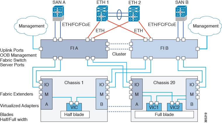
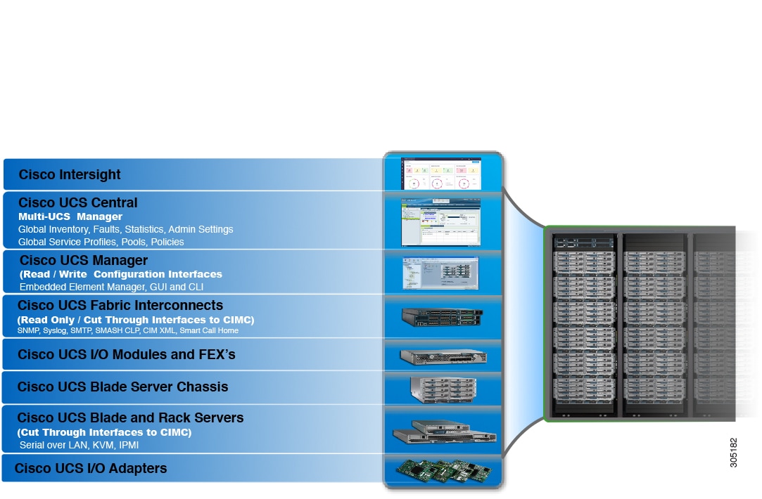
Overview |
Conceptual overview of Cisco UCS architecture including Cisco Fabric Interconnects, I/O Module and key server components; Introduction to Cisco UCS Central. |
|
System Requirements |
Hardware, browser, and port requirements for Cisco UCS Manager initial configuration. |
|
Initial Configuration |
|
|
Appendix |
Recommendations, best practices, configuration examples, and a glossary. |


 Feedback