Preparing For Component Replacement
This section contains procedures that are referred to from the replacement procedures.
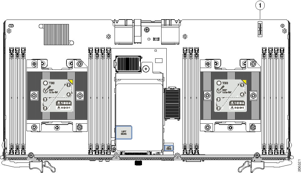
Removing an S3260 M5 Server Node or I/O Expander Top Cover
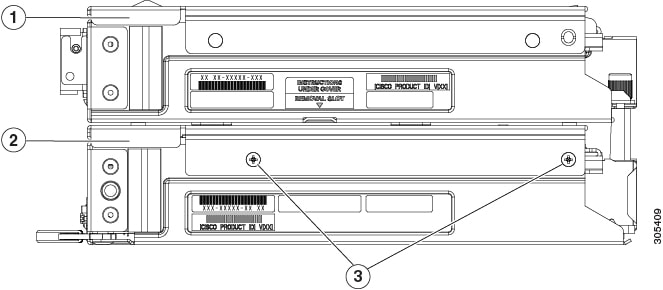
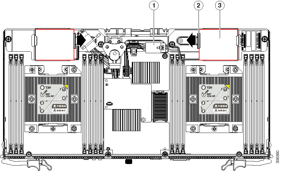
The optional I/O expander and the server node use the same top cover. If an I/O expander is attached to the top of the server node, the top cover is on the I/O expander, as shown in the side view in the following figure. In this case, there is also an intermediate cover between the server node and the I/O expander.
|
1 |
Top Cover In this view, the top cover is on the attached I/O expander. |
3 |
Intermediate cover securing screws (two on each side) |
|
2 |
Intermediate cover In this view, the intermediate cover is attached to the server node. |
- |
 Note |
You do not have to power off the chassis in the next step. Replacement with the chassis powered on is supported if you shut down the server node before removal. |
Procedure
| Step 1 |
Shut down the server node by using the software interface or by pressing the node power button, as described in Shutting Down an S3260 M5 Server Node. |
||||
| Step 2 |
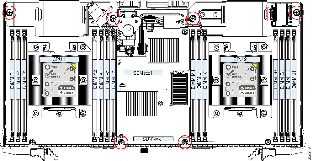
Remove the server node from the system (or server node with attached I/O expander, if present):
|
||||
| Step 3 |
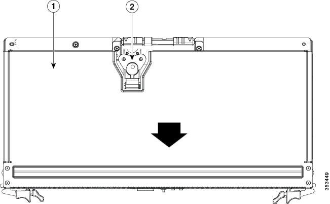
Remove the top cover from the server node or the I/O expander (if present):
|
||||
| Step 4 |
Reinstall the top cover:
|
||||
| Step 5 |
Reinstall the server node to the chassis:
|
||||
| Step 6 |
Power on the server node. |
Removing an I/O Expander From a Server Node
This topics in this section describe how to remove and then reinstall an I/O expander and intermediate cover from a server node so that you can access the components inside the server node.
Note |
You do not have to power off the chassis in the next step. Replacement with the chassis powered on is supported if you shut down the server node before removal. |
Disassembling the I/O Expander Assembly
Procedure
| Step 1 |
Shut down the server node by using the software interface or by pressing the node power button, as described in Shutting Down an S3260 M5 Server Node. |
||||
| Step 2 |
Remove the server node with attached I/O expander from the system:
|
||||
| Step 3 |
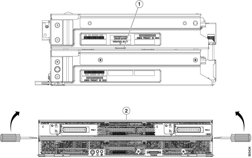
Remove the top cover from the I/O expander:
|
||||
| Step 4 |
Remove the I/O expander from the server node:
|
||||
| Step 5 |
Remove the intermediate cover from the server node:
|
||||
| Step 6 |
Install the server node (with attached I/O expander, if present) to the chassis:
|
||||
| Step 7 |
Power on the server node. |
Reassembling the I/O Expander Assembly
Before you begin
This procedure assumes that you have already taken apart the I/O expander/server node assembly.
Procedure
| Step 1 |
Reinstall the intermediate cover to the server node:
|
||||||||||||
| Step 2 |
Reinstall the I/O expander to the server node:
|
||||||||||||
| Step 3 |
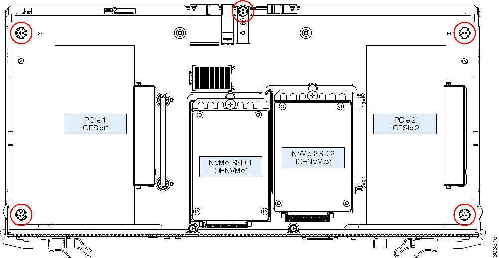
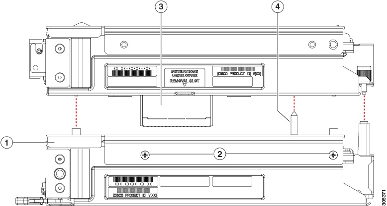
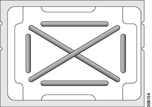
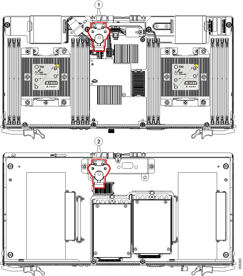
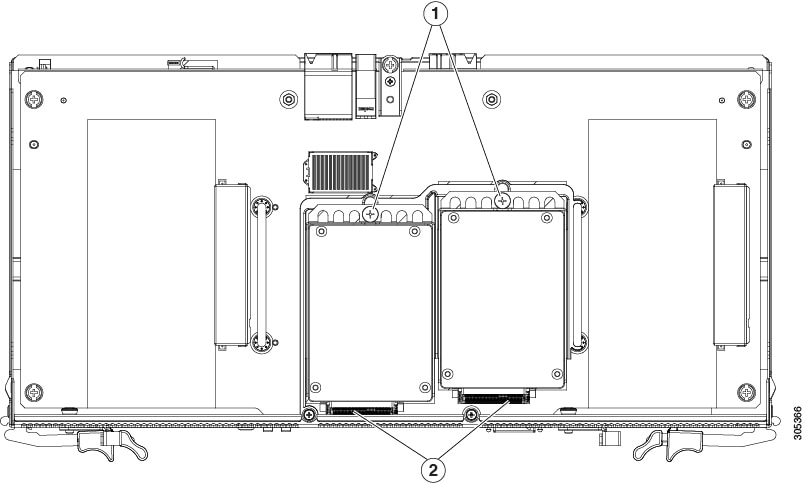
Insert the four pegs of the alignment tool into the holes that are built into the connector side of the server node and I/O expander. Ensure that the alignment tool fits into all four holes and lies flat. The alignment tool is shipped with systems that are ordered with an I/O expander. It is also shipped with I/O expander replacement spares. You can order the tool using Cisco PID UCSC-C3K-M4IOTOOL. 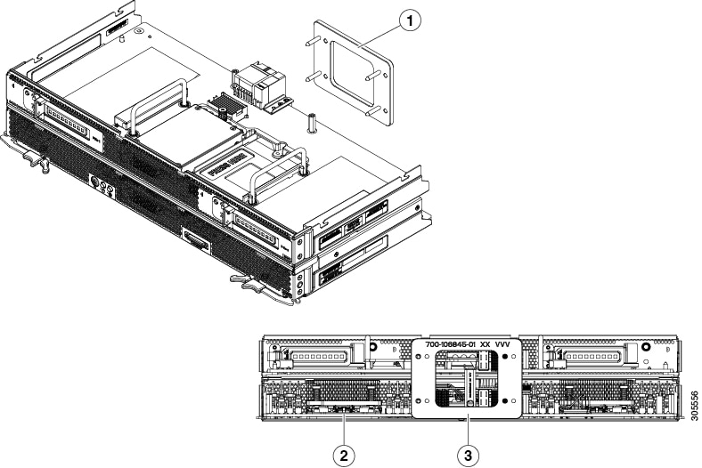
|
||||||||||||
| Step 4 |
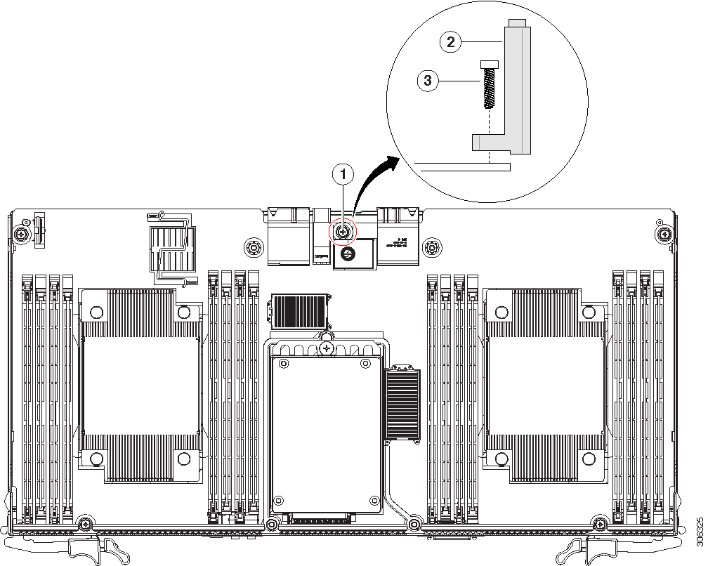
Reinstall and tighten the five screws that secure the I/O expander to the top of the server node. |
||||||||||||
| Step 5 |
Remove the alignment tool. |
||||||||||||
| Step 6 |
Reinstall the top cover to the I/O expander:
|
||||||||||||
| Step 7 |
Reinstall the server node to the chassis:
|
||||||||||||
| Step 8 |
Power on the server node. |


 Feedback