Upgrading Firmware

This chapter includes the following sections:

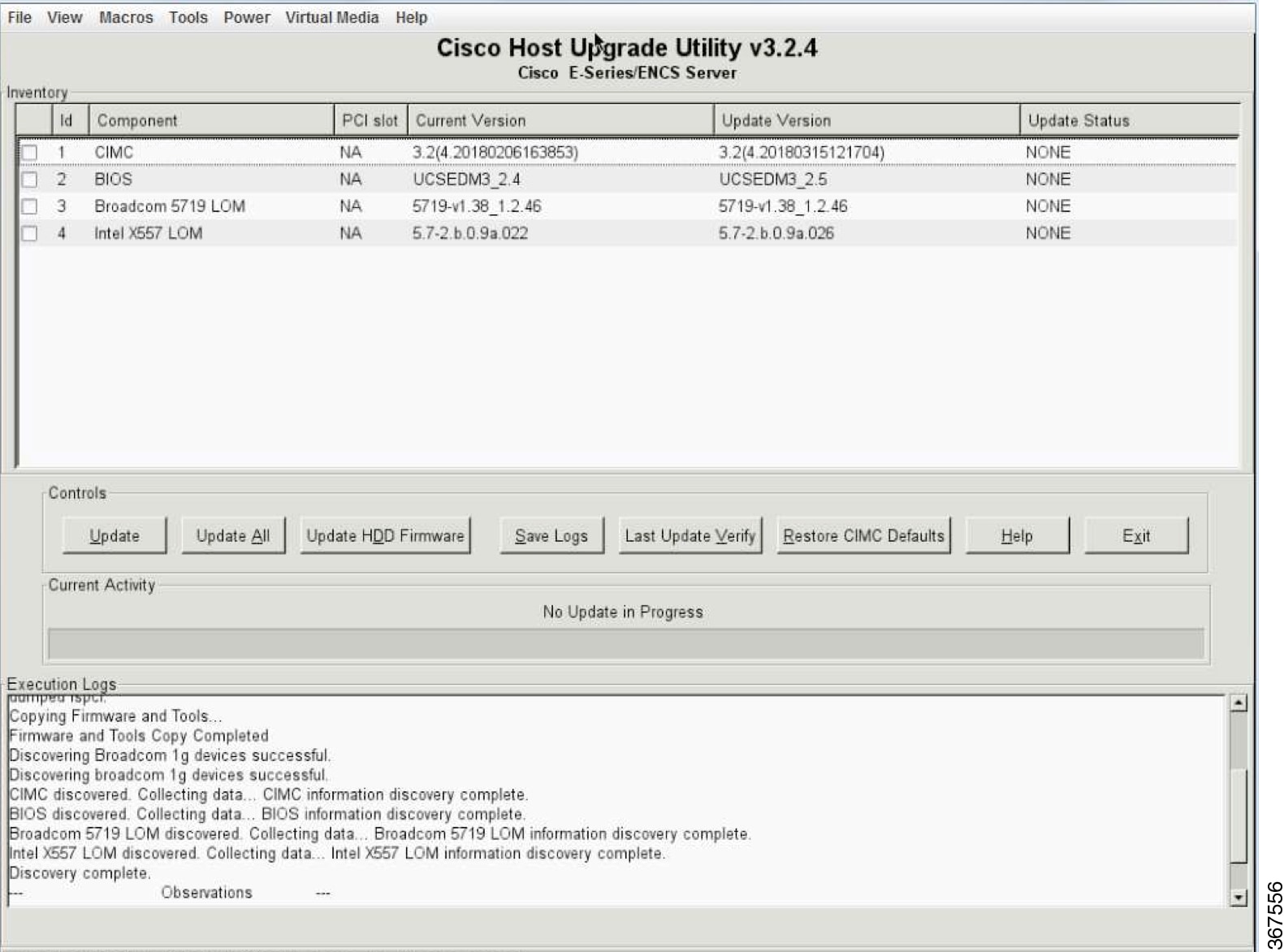
Options for Upgrading Firmware

You can use either the Cisco Host Upgrade Utility (HUU) to upgrade the firmware components or you can upgrade the firmware components manually.

  • HUU—We recommend that you use the HUU ISO file to upgrade all firmware components, which include the CIMC and BIOS firmware.

  • Manual Upgrade—To manually upgrade the CIMC and BIOS firmware, you must first obtain the firmware from Cisco Systems, and then use the CIMC GUI or the CIMC CLI to upgrade it. After you upgrade the firmware, reboot the system.

Cisco Host Upgrade Utility Overview

The Cisco Host Upgrade Utility (HUU) is a tool that you can use to upgrade the firmware on the Cisco UCS E-Series Servers (E-Series Servers) and the Cisco UCS E-Series Network Compute Engine (NCE). The HUU provides a web-based GUI where you can choose all or specific firmware components to upgrade.

The following firmware components are available for upgrade:

  • Cisco Integrated Management Controller (CIMC)

  • System BIOS

  • LAN on motherboard (LOM)

  • RAID controllers

  • Broadcom PCI adapters:
    • 5709 Dual and Quad port adapters

    • 57712 Dual port adapter

  • LSI
    • LSI MegaRAID SAS 9240-4i


Note


Cisco UCS E Series servers do not support saving HUU logs to RAID_SD0_1.


You cannot use the HUU to upgrade the Programmable Logic Devices (PLD) firmware. You must use the Cisco IOS CLI to upgrade the PLD firmware. For details, see the "Upgrading Programmable Logic Devices Firmware on the E-Series EHWIC NCE" section in the CLI Configuration Guide for Cisco UCS E-Series Servers and the Cisco UCS E-Series Network Compute Engine.

Minimum CIMC and BIOS Firmware Releases Required to Use HUU

The HUU is supported on CIMC, release 2.1.0 and later releases. To use HUU, make sure that you upgrade both the CIMC and BIOS firmware to the release specified in the table below.

Note


The HUU is not supported on CIMC, releases 1.0 and 1.0(2). If you try to use the HUU on a server that has an older release of CIMC, you will get an error message asking you to upgrade the firmware.


The following table provides information about the minimum CIMC and BIOS releases required to use the HUU.
Table 1. Minimum CIMC and BIOS Firmware Releases Required to Use HUU

Minimum Compatible CIMC Release

Minimum Compatible BIOS Release

2.1.0

1.5.0.2

CIMC and BIOS Firmware Releases Available With HUU ISO Images

The following table provided the CIMC and BIOS firmware releases that are available for upgrade when you install a specific HUU ISO image.

Table 2. CIMC and BIOS Firmware Releases Available With HUU ISO Images

HUU ISO Image

Contains CIMC Release

Contains BIOS Release

3.1.1

3.1.1

UCSEN.1.5.0.3—Applicable to the EHWIC E-Series NCE and the NIM E-Series NCE (UCS-EN120E and UCS-EN140N-M2)

UCSES.1.5.0.2—Applicable to the single-wide E-Series Server (UCS-E140S-M1, UCS-EN120S-M2 and UCS-E140S-M2)

UCSED.2.5.0.3—Applicable to the double-wide E-Series Servers (UCS-E140D-M1, UCS-E160D-M1, UCS-E160D-M2 and UCS-E180D-M2)

3.1.2

3.1.2

UCSEN.1.5.0.3—Applicable to the EHWIC E-Series NCE and the NIM E-Series NCE (UCS-EN120E and UCS-EN140N-M2)

UCSES.1.5.0.2—Applicable to the single-wide E-Series Server (UCS-E140S-M1, UCS-EN120S-M2 and UCS-E140S-M2)

UCSED.2.5.0.3—Applicable to the double-wide E-Series Servers (UCS-E140D-M1, UCS-E160D-M1, UCS-E160D-M2 and UCS-E180D-M2)

3.1.3

3.1.3

UCSEN.1.5.0.3—Applicable to the EHWIC E-Series NCE and the NIM E-Series NCE (UCS-EN120E and UCS-EN140N-M2)

UCSES.1.5.0.2—Applicable to the single-wide E-Series Server (UCS-E140S-M1)

UCSES.1.5.0.5—Applicable to the single-wide E-Series Server (UCS-EN120S-M2 and UCS-E140S-M2)

UCSED.2.5.0.3—Applicable to the double-wide E-Series Servers (UCS-E140D-M1, UCS-E160D-M1, UCS-E160D-M2 and UCS-E180D-M2)

3.1.4

3.1.4

UCSEN.1.5.0.3—Applicable to the EHWIC E-Series NCE and the NIM E-Series NCE (UCS-EN120E and UCS-EN140N-M2)

UCSES.1.5.0.2—Applicable to the single-wide E-Series Server (UCS-E140S-M1)

UCSES.1.5.0.5—Applicable to the single-wide E-Series Server (UCS-EN120S-M2 and UCS-E140S-M2)

UCSED.2.5.0.3—Applicable to the double-wide E-Series Servers (UCS-E140D-M1, UCS-E160D-M1, UCS-E160D-M2 and UCS-E180D-M2)

UCSEM3.1.0—Applicable to the single-wide E-Series Server (UCS-E160S-M3)

3.2.2

3.2.2

UCSEN.1.5.0.5—Applicable to the EHWIC E-Series NCE and the NIM E-Series NCE (UCS-EN120E and UCS-EN140N-M2)

UCSES.1.5.0.2—Applicable to the single-wide E-Series Server (UCS-E140S-M1)

UCSES.1.5.0.6—Applicable to the single-wide E-Series Server (UCS-EN120S-M2 and UCS-E140S-M2)

UCSED.2.5.0.4—Applicable to the double-wide E-Series Servers (UCS-E140D-M1, UCS-E160D-M1, UCS-E160D-M2 and UCS-E180D-M2)

UCSEM3.2.4—Applicable to the single-wide E-Series Server (UCS-E160S-M3)

UCSEDM3.2.4—Applicable to the single-wide E-Series Server (UCS-E180D-M3 and UCS-E1120D-M3)

3.2.3

3.2.3

UCSEN.1.5.0.5—Applicable to the EHWIC E-Series NCE and the NIM E-Series NCE (UCS-EN120E and UCS-EN140N-M2)

UCSES.1.5.0.2—Applicable to the single-wide E-Series Server (UCS-E140S-M1)

UCSES.1.5.0.6—Applicable to the single-wide E-Series Server (UCS-EN120S-M2 and UCS-E140S-M2)

UCSED.2.5.0.4—Applicable to the double-wide E-Series Servers (UCS-E140D-M1, UCS-E160D-M1, UCS-E160D-M2 and UCS-E180D-M2)

UCSEM3.2.4—Applicable to the single-wide E-Series Server (UCS-E160S-M3)

UCSEDM3.2.4—Applicable to the single-wide E-Series Server (UCS-E180D-M3 and UCS-E1120D-M3)

3.2.4

3.2.4

UCSEN.1.5.0.5—Applicable to the EHWIC E-Series NCE and the NIM E-Series NCE (UCS-EN120E and UCS-EN140N-M2)

UCSES.1.5.0.2—Applicable to the single-wide E-Series Server (UCS-E140S-M1)

UCSES.1.5.0.7—Applicable to the single-wide E-Series Server (UCS-EN120S-M2 and UCS-E140S-M2)

UCSED.2.5.0.5—Applicable to the double-wide E-Series Servers (UCS-E140D-M1, UCS-E160D-M1, UCS-E160D-M2 and UCS-E180D-M2)

UCSEM3.2.5—Applicable to the single-wide E-Series Server (UCS-E160S-M3)

UCSEDM3.2.5—Applicable to the single-wide E-Series Server (UCS-E180D-M3 and UCS-E1120D-M3)

Understanding the HUU User Interface

Figure 1. HUU User Interface

User Interface Name

Description

Id column

Displays the serial number of the component row.

Component column

Lists the firmware components that are available for upgrade.

PCI Slot column

Display the PCI slot information for the PCI adapter components.

Current Version column

Displays the current firmware version number that is installed for each of the listed components.

Update Version column

Displays the firmware version number that is available for upgrade for each of the listed components.

Update Status column

Displays the status of the update for each of the listed components while the update is in progress.

Update button

Initiates the firmware update for a selected component.

Update All button

Initiates the firmware update for all available components.

Save Logs button

Saves the log files.

If an error occurs while updating the firmware, you are prompted to save the error log. Click the Save Logs button to save the error logs to an externally connected USB. This log can be used to identify the cause of the error and for troubleshooting.

Last Update Verify button

Verifies if the update was successful.

Note


You must first reboot HUU by clicking the Exit button, and then click the Last Update Verify button to verify the last update.

Restore CIMC Defaults button

Restores the CIMC settings to factory default settings.

Exit button

Exits the HUU. Click Yes at the confirmation prompt to exit.

  • If you update the CIMC and not the BIOS, when you click the Exit button, the CIMC will get activated but you will lose connectivity to the CIMC and KVM.
  • If you select LOM for update and you are in shared LOM mode, when you click the Exit button, you will lose connectivity to the CIMC and KVM.

Usage area

Lists keyboard shortcuts that you can use to perform specific tasks.

Current Activity area

Provides the status of an update.

Execution Logs area

Provides a log of activities and their status while an update is in progress.

Upgrading the Firmware

Basic Workflow for Using the HUU

  1. Download the HUU ISO image from Cisco.com.

  2. Use the KVM console or the CIMC CLI to map the HUU ISO image.

  3. Set the boot order to make the virtual CD/DVD drive as the boot device.

  4. From the HUU GUI, select all or specific firmware components to update.

  5. After the firmware updates, click Exit to reboot the HUU.

  6. Unmap the HUU ISO image.

  7. Reboot the server.

Upgrading the Firmware Using the HUU

Procedure


Step 1

Navigate to http://www.cisco.com/.

Step 2

If you are not already logged in, click Log In at the top-right edge of the page and log in using your Cisco.com credentials.

Step 3

In the menu bar at the top, click Support.

A roll-down menu appears.

Step 4

From the Downloads (center) pane, click All Downloads (located at the bottom right corner).

The Download Software page appears.

Step 5

From the left pane, click Products.

Step 6

From the center pane, click Servers—Unified Computing.

Step 7

From the right pane, click Cisco UCS E-Series Software.

Step 8

From the right pane, click the name of the server model for which you want to download the software.

The Download Software page appears.

Step 9

Click Unified Computing System (UCSE) Server Firmware.

Step 10

Click the Download button associated with the Cisco UCS Host Upgrade Utility ISO image to download the image onto your PC.

The End User License Agreement dialog box appears.

Step 11

Click Accept License Agreement.

Step 12

The Opening ucse-server-platform-huu.iso dialog box appears.

Either open the file or browse to the location where you want to save the HUU ISO image, and then click OK.

Step 13

You can use either the KVM Console or the CIMC CLI to map the HUU ISO image:

  • To use the KVM Console, do the following:
    1. Use a browser to connect to the CIMC GUI on the server that you are upgrading.

    2. In the address field of the browser, enter the CIMC IP address for that server, and then enter your username and password to log in to the CIMC GUI.

    3. Click the Launch KVM Console icon on the toolbar. The KVM Console opens in a separate window.

    4. From the KVM Console, click the Virtual Media tab.

    5. Click Add Image, navigate to and select the Host Upgrade Utility ISO image, and then click Open to mount the image.

    6. In the Client View area, in the Mapped column, check the check box for the mounted ISO image.


  • To use the CIMC CLI, download the ISO image on to an FTP or TFTP server, and then use the following commands:
    1. Server# scope host-image-mapping.

    2. Server/host-image-mapping # download-image protocol server-ip-address huu-ISO-filename

    3. Server/host-image-mapping # map-image huu-ISO-filename.

    Server# scope host-image-mapping
    Server/host-image-mapping # download-image ftp 10.20.34.56 2.1.1.iso
    Username: anonymous
    Password: 
    Image download has started.
    Please check the status using "show detail".
    Server/host-image-mapping # map-image 2.1.1.iso
    

Step 14

After the image is mapped, set the boot order to make the virtual CD/DVD drive as the boot device.

Step 15

Reboot the server.

Step 16

From the CIMC GUI, click the Launch KVM Console icon on the toolbar.

The HUU and the Cisco Software License Agreement page appears.

Step 17

Click I Agree to accept the licensing terms and conditions.

The Cisco Host Upgrade Utility GUI appears with a list of components that are available for update.

Step 18

Do one of the following:

  • To update all the listed components, click Update all.
  • To update specific components, select the components, and then click Update.

The status of the update is displayed in the Update Status column. To view details about the update status, see the Execution Logs area.

Note


We recommend that you always update the BIOS and the CIMC firmware at the same time.

Step 19

After the firmware is updated, click Exit, and then click Ok at the confirmation prompt.

The HUU reboots.

Important

 
  • If the BIOS firmware is selected for update, it will be the last one to update because it requires the host to be powered off. You can check the progress of the BIOS update from the CIMC GUI or CIMC CLI. After the BIOS update completes, you must use the CIMC GUI or the CIMC CLI to manually power on the host.

  • If the CIMC firmware is selected for update—after you click the Exit button from the HUU GUI—the new CIMC firmware gets automatically activated. However, if both the BIOS and CIMC firmwares are selected for update, the CIMC firmware does not get automatically activated. You must use the CIMC GUI or the CIMC CLI to manually activate the new CIMC firmware.

  • When the new CIMC firmware gets activated, you will lose network connectivity to the CIMC GUI, CIMC CLI, and virtual KVM. Also, the mapped HUU ISO image gets unmapped. To run the HUU, you must map the HUU ISO image again.

  • When the LOM firmware is updated, you might lose network connectivity to the CIMC GUI and virtual KVM.

Step 20

Unmap the HUU ISO image. Do one of the following:

  • From the CIMC GUI, click the Launch KVM Console icon on the toolbar, from the Mapped column, check the check box for the mounted HUU ISO image, and then click Remove Image.
  • From the CIMC CLI, use the unmap-image command:
  • Server/host-image-mapping # unmap-image

Step 21

Reboot the server.


Troubleshooting

Problem

Solution

Connection to the CIMC is lost after an update and reboot, and the KVM session ends.

This is expected behavior after a firmware update. Log back in to the CIMC, and then re-establish your KVM session.

Error Message:
PID, Board-Part-Number, Product-Part-Number is not supported by this HUU image. HUU will not boot on this machine. Press any key to reboot the server.

This error message displays when the HUU ISO image is not supported by the server. To resolve this problem, use the HUU ISO image that is supported by the server. See Minimum CIMC and BIOS Firmware Releases Required to Use HUU.

After using the HUU to update the Broadcom NCSI firmware, the warning prompt to update the Broadcom firmware still displays in the CIMC GUI and the CIMC CLI.

To resolve this problem, power cycle the E-Series Server to allow the new Broadcom NCSI firmware to take effect.

BIOS Overview

BIOS initializes the hardware in the system. After it initializes the CPU, other chips on the motherboard get initialized. BIOS discovers bootable devices in the system and boots them in the provided sequence. It boots the operating system and configures the hardware for the operating system to use. BIOS manageability features allow you to interact with the hardware and use it. In addition, BIOS provides options to configure the system, manage firmware, and create BIOS error reports.

BIOS provides the following features:

  • Option ROM to provide PCI connected device boot

  • Manage virtual and physical boot devices: SCSI, FC, network, and USB

  • Processor Settings

  • Memory Settings

  • Power Management (C-states)

BIOS supports the following standard PC compatible functionality:

  • ACPI 3.0, SMBIOS 2.5, WHEA, and USB 2.0

  • EFI Shell boot

  • EFI native operating system boot

Determining the Current BIOS Version

To view the current version and build number of the BIOS, press F2 during server bootup. The BIOS setup utility appears. The listing on the Main page displays the current version and build number of the BIOS.

Obtaining Software from Cisco Systems

Use this procedure to download BIOS and CIMC firmware.

Procedure


Step 1

Navigate to http://www.cisco.com/.

Step 2

If you are not already logged in, click Log In at the top right-hand edge of the page and log in using your Cisco.com credentials.

Step 3

In the menu bar at the top, click Support.

A roll-down menu appears.

Step 4

From the Downloads (center) pane, click All Downloads (located at the bottom right corner).

The Download Software page appears.

Step 5

From the left pane, click Products.

Step 6

From the center pane, click Unified Computing and Servers.

Step 7

From the right pane, click Cisco UCS E-Series Software.

Step 8

From the right pane, click the name of the server model for which you want to download the software.

The Download Software page appears with the following categories.

  • Unified Computing System (UCSE) Server Firmware—Contains the Host Upgrade Utility.

Step 9

Click the appropriate software category link.

Step 10

Click the Download button associated with software image that you want to download.

The End User License Agreement dialog box appears.

Step 11

(Optional) To download multiple software images, do the following:

  1. Click the Add to cart button associated with the software images that you want to download.

  2. Click the Download Cart button located on the top right .

    All the images that you added to the cart display.

  3. Click the Download All button located at the bottom right corner to download all the images.

    The End User License Agreement dialog box appears.

Step 12

Click Accept License Agreement.

Step 13

Do one of the following as appropriate:

  • Save the software image file to a local drive.

  • If you plan to install the software image from a TFTP server, copy the file to the TFTP server that you want to use.

    The server must have read permission for the destination folder on the TFTP server.


What to do next

Install the software image.

Upgrading Firmware Manually

You can upgrade the firmware manually, through the browser or from a TFTP server. For details, see the Firmware Management chapter in the GUI Configuration Guide for Cisco UCS E-Series Servers and the Cisco UCS E-Series Network Compute Engine or the CLI Configuration Guide for Cisco UCS E-Series Servers and the Cisco UCS E-Series Network Compute Engine.

Installing the BIOS Firmware Through the Browser


Note


To avoid potential problems, we strongly recommend that you use the Host Upgrade Utility (HUU), which upgrades the CIMC, BIOS, and other firmware components to compatible levels. For detailed information about this utility, see the "Upgrading Firmware" chapter in the Getting Started Guide for Cisco UCS E-Series Servers and the Cisco UCS E-Series Network Compute Engine. This chapter also provides information about the compatible HUU, CIMC, and BIOS software releases.

If you choose to upgrade the CIMC and BIOS firmware manually—instead of using the HUU—you must update the CIMC firmware first, and then the BIOS firmware. Do not install the new BIOS firmware until after you have activated the compatible CIMC firmware or the server will not boot.


Before you begin

  • Log in to CIMC as a user with admin privileges.

  • Obtain the CIMC firmware file from Cisco Systems. See Obtaining Software from Cisco Systems.

  • Unzip the proper upgrade file to your local machine.

Procedure


Step 1

In the Navigation pane, click the Server menu.

Step 2

On the Server tab, click BIOS.

Step 3

In the Firmware Actions area, click Install BIOS Firmware through Browser Client.

Step 4

In the Install BIOS Firmware dialog box, click Browse and use the Choose File dialog box to select the file to install.

Step 5

Click Install Firmware.

The BIOS is downloaded, the host is powered off, the BIOS is upgraded, and then the host is powered on.


Installing the BIOS Firmware from a TFTP Server


Note


To avoid potential problems, we strongly recommend that you use the Host Upgrade Utility (HUU), which upgrades the CIMC, BIOS, and other firmware components to compatible levels. For detailed information about this utility, see the "Upgrading Firmware" chapter in the Getting Started Guide for Cisco UCS E-Series Servers and the Cisco UCS E-Series Network Compute Engine. This chapter also provides information about the compatible HUU, CIMC, and BIOS software releases.

If you choose to upgrade the CIMC and BIOS firmware manually—instead of using the HUU—you must update the CIMC firmware first, and then the BIOS firmware. Do not install the new BIOS firmware until after you have activated the compatible CIMC firmware or the server will not boot.


Before you begin

  • Log in to CIMC as a user with admin privileges.

  • Obtain the CIMC firmware file from Cisco Systems. See Obtaining Software from Cisco Systems.

  • Unzip the proper upgrade file on your TFTP server.

Procedure


Step 1

In the Navigation pane, click the Server menu.

Step 2

On the Server tab, click BIOS.

Step 3

In the Firmware Actions area, click Install BIOS Firmware from TFTP Server.

Step 4

In the Install BIOS Firmware dialog box, complete the following fields:

Name Description

TFTP Server IP Address field

The IP address of the TFTP server on which the BIOS firmware image resides.

Image Path and Filename field

The BIOS firmware image filename on the server. When you enter this name, include the relative path for the image file from the top of the TFTP tree to the file location.

Step 5

Click Install Firmware.

The BIOS is downloaded, the host is powered off, the BIOS is upgraded, and then the host is powered on.


Accessing the BIOS Setup Menu

You can access the BIOS Setup menu in two ways:

  • Through CIMC from the KVM console.

  • Through a console that is physically attached to the E-Series Server.

Accessing the BIOS Setup Menu from the KVM Console

Procedure


Step 1

In the Navigation pane, click the Server menu.

Step 2

In the work pane, click Host Image Mapping tab.

Step 3

From the Actions area, click Launch KVM Console.

The KVM Console opens in a separate window.

Step 4

From the Server Summary page, click Power Cycle Server to reboot the server.

Step 5

To access the BIOS setup menu, press F2 during bootup.

The Aptio Setup Utility appears, which provides the BIOS setup menu options.

Figure 2. BIOS Setup Menu


The following table provides information about the BIOS setup menu tabs.

Tabs

Description

Main tab

Provides the following:

  • General information about the BIOS version, system memory, and access level

  • Settings to define the system date, time, and language

Advanced tab

Allows you to do the following:

  • Enable or disable boot option for legacy network devices and legacy mass storage devices with option ROM

  • Configure PCI, PCI-X, and PCI express, trusted computing settings, and WHEA configuration settings

  • Configure CPU, thermal, USB, and system IO chip parameters

  • Configure runtime error logging support setup options

  • Configure console redirection to the serial port

Chipset tab

Allows you to do the following:

  • Define North Bridge, South Bridge, and ME subsystem parameters

Server Mgmt tab

Provides the self test status of CIMC and allows you to do the following:

  • Enable or disable interfaces to communicate with CIMC

  • Enable or disable FRB-2 timer

  • Configure the FRB-2 timer expiration value and configure how the system responds when the FRB-2 timer expires

  • Enable or disable the OS watchdog timer

  • Log the report returned by the CIMC self test command

  • Change the system event log configuration

Boot tab

Allows you to do the following:

  • Configure the time in seconds the system should wait for the setup activation key

  • Enable or disable the keyboard NumLock keys

  • Define boot order rules

  • Configure Gate A20 parameters

  • Enable or disable CSM support

  • Define boot order for devices in the following groups: hard disk drives, network devices, CDROM, DVD, and floppy drives

Security tab

Allows you to do the following:

  • Define or change the BIOS administrator and user passwords

Save & Exit tab

Provides options to do the following:

  • Save changes, discard changes, or restore the configuration to its default settings


Changing Configuration Using the BIOS Setup Menu

Use this procedure to change the BIOS settings for your server. Detailed instructions are also printed on the BIOS pages.

Procedure


Step 1

In the Navigation pane, click the Server menu.

Step 2

In the work pane, click Host Image Mapping tab.

Step 3

From the Actions area, click Launch KVM Console.

The KVM Console opens in a separate window.

Step 4

From the Server Summary page, click Power Cycle Server to reboot the server.

Step 5

To access the BIOS setup menu, press F2 during bootup.

The Aptio Setup Utility appears, which provides the BIOS setup menu options.

Figure 3. BIOS Setup Menu


Step 6

To navigate between menu items, use the right or left arrow keys on your keyboard.

Step 7

To modify a field, do the following:

  1. Use the Up or Down arrow keys on your keyboard to highlight the field to be modified.

  2. Press Enter to select the highlighted field, and then change the value in the field.

  3. Do one of the following:

  • To save changes and exit the BIOS setup, press F4.
  • To exit without saving changes, press Esc.

Step 8

To enable or disable a field, press the space bar on your keyboard.