Managing Storage Using RAID


Note


If you purchased E-Series Server Option 1 (E-Series Server without a preinstalled operating system or hypervisor), and you want to store data files on local Redundant Array of Inexpensive Disks (RAID), you must configure RAID.


Important


The RAID feature is applicable to E-Series Servers and the SM E-Series NCE. The RAID feature is not applicable to the EHWIC E-Series NCE and the NIM E-Series NCE.


This chapter includes the following sections:

RAID Options


Note


The RAID feature is applicable to E-Series Servers and the SM E-Series NCE. The RAID feature is not applicable to the EHWIC E-Series NCE and the NIM E-Series NCE.

You can choose to store the E-Series Server data files on local Redundant Array of Inexpensive Disks (RAID). The following RAID levels are supported:

  • The single-wide E-Series Server supports RAID 0 and RAID 1 levels.

  • The double-wide E-Series Server supports RAID 0, RAID 1, and RAID 5 levels.

  • The double-wide E-Series Server with the PCIe option supports RAID 0 and RAID 1 levels.

RAID 0

With RAID 0, the data is stored evenly in stripe blocks across one or more disk drives without redundancy (mirroring). The data in all of the disk drives is different.

Figure 1. RAID 0

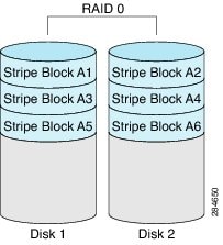
Compared to RAID 1, RAID 0 provides additional storage because both disk drives are used to store data. The performance is improved because the read and write operation occurs in parallel within the two disk drives.

However, there is no fault tolerance, error checking, hot spare, or hot-swapping. If one disk drive fails, the data in the entire array is destroyed. Because there is no error checking or hot-swapping, the array is susceptible to unrecoverable errors.

RAID 1

RAID 1 creates a mirrored set of disk drives, where the data in both the disk drives is identical, providing redundancy and high availability. If one disk drive fails, the other disk drive takes over, preserving the data.

RAID 1 also allows you to use a hot spare disk drive. The hot spare drive is always active and is held in readiness as a hot standby drive during a failover.

Figure 2. RAID 1

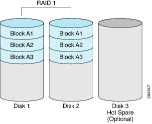
RAID 1 supports fault tolerance and hot-swapping. When one disk drive fails, you can remove the faulty disk drive and replace it with a new disk drive.

However, compared to RAID 0, there is less storage space because only half of the total potential disk space is available for storage and there is an impact on performance.

RAID 5

With RAID 5, the data is stored in stripe blocks with parity data staggered across all disk drives, providing redundancy at a low cost.

Figure 3. RAID 5

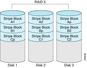
RAID 5 provides more data storage capacity than RAID 1 and better data protection than RAID 0. It also supports hot swapping; however, RAID 1 offers better performance.

RAID 10

RAID 10, a combination of RAID 0 and RAID 1, consists of striped data across mirrored spans. A RAID 10 drive group is a spanned drive group that creates a striped set from a series of mirrored drives. RAID 10 allows a maximum of eight spans. You must use an even number of drives in each RAID virtual drive in the span. The RAID 1 virtual drives must have the same stripe size. RAID 10 provides high data throughput and complete data redundancy but uses a larger number of spans.


Note


RAID 10 is supported on DoubleWide M3 servers.


Non-RAID

When the disk drives of a computer are not configured as RAID, the computer is in non-RAID mode. Non-RAID mode is also referred to as Just a Bunch of Disks or Just a Bunch of Drives (JBOD). Non-RAID mode does not support fault tolerance, error checking, hot-swapping, hot spare, or redundancy.

Summary of RAID Options

RAID Option Description Advantages Disadvantages

RAID 0

Data stored evenly in stripe blocks without redundancy

  • Better storage

  • Improved performance

  • No error checking

  • No fault tolerance

  • No hot-swapping

  • No redundancy

  • No hot spare

RAID 1

Mirrored set of disk drives and an optional hot spare disk drive

  • High availability

  • Fault tolerance

  • Hot spare

  • Hot-swapping

  • Less storage

  • Performance impact

RAID 5

Data stored in stripe blocks with parity data staggered across all disk drives

  • Better storage efficiency than RAID 1

  • Better fault tolerance than RAID 0

  • Low cost of redundancy

  • Hot-swapping

  • Slow performance

Non-RAID

Disk drives not configured for RAID

Also referred to as JBOD

  • Portable

  • No error checking

  • No fault tolerance

  • No hot-swapping

  • No redundancy

  • No hot spare

Configuring RAID

You can choose to store the E-Series Server data files on local Redundant Array of Inexpensive Disks (RAID). The following RAID levels are supported:

  • The single-wide E-Series Server supports RAID 0 and RAID 1 levels.

  • The double-wide E-Series Server supports RAID 0, RAID 1, and RAID 5 levels.

  • The double-wide E-Series Server with the PCIe option supports RAID 0 and RAID 1 levels.


Note


On Cisco UCS M1 and M2 servers, you can use the CIMC GUI or the WebBIOS, which is accessible from the KVM console, to configure RAID. On Cisco UCS M3 servers, you can use the CIMC GUI or the MegaRAID controller, which is accessible from the KVM console, to configure RAID.


Configuring RAID Using the CIMC GUI

Use this procedure to configure the RAID level, strip size, host access privileges, drive caching, and initialization parameters on a virtual drive. You can also use this procedure to designate the drive as a hot spare drive and to make the drive bootable.

Procedure


Step 1

In the Navigation pane, click the Server menu.

Step 2

On the Server tab, click Inventory.

Step 3

In the Inventory pane, click the Storage tab.

Step 4

To configure RAID, make sure that the status of each of the physical drives that you want to configure as RAID is unconfigured good. To change the physical drive status, do the following:

  1. In the tabbed menu of the Storage Card area, click the Physical Drive Info tab.

    Figure 4. Physical Drive Info Tab


  2. From the Actions column in the Physical Drives pane, choose Set State from the drop-down list.

    The Change Physical Drive State dialog box appears.

  3. From the Change Physical Drive State to drop-down list, choose unconfigured good, and then click Confirm.

Step 5

In the tabbed menu of the Storage Card area, click the Virtual Drive Info tab.

Figure 5. Virtual Drive Info Tab


Step 6

In the Actions area of the Virtual Drive Info tab, click Create.

The Configure Virtual Drive dialog box appears. Complete the following fields as appropriate:

Name Description

RAID Level drop-down list

The RAID level options. This can be one of the following:

  • RAID 0—Block striping.

  • RAID 1—Mirroring.

  • RAID 5—Block striping with parity.

Note


The single-wide E-Series Server supports RAID 0 and RAID 1 levels. The double-wide E-Series Server supports RAID 0, RAID 1, and RAID 5 levels. The double-wide E-Series Server with PCIe option supports RAID 0 and RAID 1 levels.

Unconfigured Drives table

Displays the drives that are unconfigured and available for RAID configuration.

Add >

Moves the selected drives from the Unconfigured Drives table to the Selected Drives table.

< Remove

Removes the selected drives from the Selected Drives table.

Selected Drives table

Displays the drives that are selected for RAID configuration.

Step 7

Click Next.

The Configure RAID Parameters dialog box appears. Complete the following fields as appropriate:

Name Description

Strip Size drop-down list

The strip size options. This can be one of the following:

  • 64 KB

  • 32 KB

  • 16 KB

  • 8 KB

Caution


The smaller strip sizes have a known problem with VMware vSphere Hypervisor™ installation; therefore, if you are installing the vSphere platform, we recommend that you select the 64 KB strip size option.

Access Policy drop-down list

Configures host access privileges. This can be one of the following:

  • Read-Write—The host has full access to the drive.

  • Read Only—The host can only read data from the drive.

  • Blocked—The host cannot access the drive.

Drive Cache drop-down list

How the controller handles drive caching. This can be one of the following:

  • Unchanged—The controller uses the caching policy specified on the drive. This is the default and recommended option.

  • Enable—Caching is enabled on the drives. This option minimizes the delay in accessing data.

    Caution


    Enabling Drive Cache, voids all warranty on the hard disk drives. This configuration option is not supported. Use this option at your own risk.

  • Disable—Caching is disabled on the drives.

Initialization drop-down list

How the controller initializes the drives. This can be one of the following:

  • Quick—Controller initializes the drive quickly. This is the default and recommended option.

    Note


    If you are using SSD drives, we recommend that you choose the Quick initialization option.

  • Full—Controller does a complete initialization of the new configuration.

    Note


    Depending on the size of the drives, Full initialization can take several hours to complete.

  • None—Controller does not initialize the drives.

HSP check-box

Designates the drive as a hot spare drive.

Note


Applicable for RAID 1 only.

Set Bootable check-box

How the controller boots the drive. This can be one of the following:

  • Enable—Makes this drive bootable.

  • Disable—This drive is not bootable.

Note


If you plan to install an operating system or Hypervisor into the RAID array, we recommend that you check this check-box.

Step 8

Click Next.

The Confirm RAID Configuration dialog box appears.

Step 9

Review the RAID configuration, and then click Submit to accept the changes.


Configuring RAID


Note


On Cisco UCS M1 and M2 servers, you can use the CIMC GUI or the WebBIOS, which is accessible from the KVM console, to configure RAID. On Cisco UCS M3 servers, you can use the CIMC GUI or the MegaRAID controller, which is accessible from the KVM console, to configure RAID.


Use this procedure to configure the RAID level, strip size, host access privileges, drive caching, and initialization parameters on a virtual drive. You can also use this procedure to designate the drive as a hot spare drive and to make the drive bootable.

Procedure


Step 1

In the Navigation pane, click the Server menu.

Step 2

On the Server tab, click RAID. Do one of the following:

  • If the Configure Virtual Drive dialog box does not appear, proceed to the next step.

  • If the Configure Virtual Drive dialog box appears, and the virtual drives are not configured, complete the fields as shown in Step 5.

Step 3

In the tabbed menu of the Storage Cards area, click the Virtual Drive Info tab.

Step 4

In the Actions area of the Virtual Drive Info tab, click Create.

Step 5

Complete the following fields as appropriate:

Name Description

Available Drives table

Displays the drives that are available for RAID configuration.

Note


To move a drive, click and drag a drive to the appropriate table.

Selected Drives table

Displays the drives that are selected for RAID configuration.

Note


To move a drive, click and drag a drive to the appropriate table.

RAID Level drop-down list

The RAID level options. This can be one of the following:

  • RAID 0—Block striping.

  • RAID 1—Mirroring.

  • RAID 5—Block striping with parity.

Note


The single-wide E-Series Server supports RAID 0 and RAID 1 levels. The double-wide E-Series Server supports RAID 0, RAID 1, and RAID 5 levels. The double-wide E-Series Server with the PCIe option supports RAID 0 and RAID 1 levels.

Name field

The name of the virtual drive.

Enter a maximum of 15 characters. The characters can have numbers and upper- or lower-case letters. Special characters are not supported.

Strip Size drop-down list

The strip size options. This can be one of the following:

  • 64 KB

  • 32 KB

  • 16 KB

  • 8 KB

Initialization drop-down list

How the controller initializes the drives. This can be one of the following:

  • Quick—The controller initializes the drive quickly. This is the default and recommended option.

  • Full—The controller does a complete initialization of the new configuration.

    Note


    Depending on the size of the drives, full initialization can take several hours to complete. To view the progress, see the Initialize Progress and Initialize Time Elapsed fields in the General area.

  • None—The controller does not initialize the drives.

Drive Cache drop-down list

How the controller handles drive caching. This can be one of the following:

  • Disable—Caching is disabled on the drives.

    Note


    This is the default and recommended option.

  • Unchanged—The controller uses the caching policy specified on the drive. This is the default and recommended option.

  • Enable—Caching is enabled on the drives. This option minimizes the delay in accessing data.

    Caution


    Enabling Drive Cache, voids all warranty on the hard disk drives. This configuration option is not supported. Use this option at your own risk.

Access Policy drop-down list

Configures host access privileges. This can be one of the following:

  • Read-Write—The host has full access to the drive.

  • Read Only—The host can read only data from the drive.

  • Blocked—The host cannot access the drive.

Set this Virtual Drive Bootable check box

How the controller boots the drive. This can be one of the following:

  • Enable—The controller makes this drive bootable.

  • Disable—This drive is not bootable.

Note


If you plan to install an operating system or hypervisor into the RAID array, we recommend that you check this check box.

Use the Remaining Drive as Hot Spare check box

Designates the drive that is in the Available Drives table as a hot spare drive.

Note


Applicable for RAID 1 only. This check box is greyed out for other RAID levels.

Applicable for double-wide E-Series Servers.

Step 6

Review the RAID configuration, and then click Confirm to accept the changes.


Configuring RAID Using the WebBIOS


Important


The RAID feature is applicable to E-Series Servers and the SM E-Series NCE. The RAID feature is not applicable to the EHWIC E-Series NCE and the NIM E-Series NCE.


Note


Use WebBIOS to configure RAID on M1 and M2 servers. Use MegaRAID controller to configure RAID on M3 servers. See Configuring RAID Using the MegaRAID Controller


Procedure


Step 1

In the Navigation pane, click the Server menu.

Step 2

In the work pane, click Host Image Mapping tab.

Step 3

From the Actions area, click Launch KVM Console.

The KVM Console opens in a separate window.

Step 4

From the Server Summary page, click Power Cycle Server to reboot the server.

Step 5

Press the Ctrl key, and then press H during bootup to access the WebBIOS.

The Adapter Selection page from LSI Logic appears, which allows you to configure RAID. For information about this page, see the LSI Logic documentation.


Configuring RAID Using the MegaRAID Controller


Important


The RAID feature is applicable to E-Series Servers and the SM E-Series NCE. The RAID feature is not applicable to the EHWIC E-Series NCE and the NIM E-Series NCE.


Procedure


Step 1

In the Navigation pane, click the Server menu.

Step 2

In the work pane, click Host Image Mapping tab.

Step 3

From the Actions area, click Launch KVM Console.

The KVM Console opens in a separate window.

Step 4

From the Server Summary page, click Power Cycle Server to reboot the server.

Step 5

Press the Ctrl key, and then press R during bootup to access the MegaRAID Controller.

The Virtual Drive Management page appears, which allows you to configure MegaRAID Controller.


Configuring RAID Using the Cisco IOS CLI

Procedure

  Command or Action Purpose

Step 1

Router> enable

Enters privileged EXEC mode on the host router. Enter your password if prompted.

Step 2

Router# ucse slot server raid level {none | 0 | 1 | 5} use hard drive list

Configures the RAID level on the specified hard drive.

Caution


When you use this command, all existing data in the hard drive is lost.

Step 3

At the confirmation prompt, enter y.

Proceeds with the RAID configuration process.

Step 4

Router# show ucse slot server raid level

(Optional) Displays the RAID configuration.

Example

This example shows how to configure RAID using the Cisco IOS CLI.


Router> enable
Router> password
Router# ucse 1 server raid level 1 use HDD1 HDD2
You are about to change RAID configuration.
It will destroy all data on the hard drives
Are you sure [y/n] y
 
RAID reconfigured 
Router# show ucse 1 server raid level 
md0 : active raid1 HDD1 [1] HDD2 [0]
      10337728 blocks [2/2] [UU]
JBOD: HDD3

What to Do Next

If you purchased E-Series Server or NCE Option 1 (E-Series Server or NCE without a preinstalled operating system or hypervisor), install the operating system. See Installing the Operating System or Hypervisor.