Configuring an Internal Connection Between the Cisco ISR G2 and the E-Series Server
-
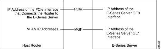
For traffic to flow through the PCIe connection (see next figure), configure the following:
-
IP address of the router's internal PCIe interface that connects the router to the E-Series Server's GE0 interface.
-
IP address of the E-Series Server's GE0 interface.
-
-
For traffic to flow through the MGF connection (see next figure), configure the following:
-
IP address of the router's internal MGF VLAN interface.
-
IP address of the E-Series Server's GE1 interface.
-
The following figure shows the internal connection between the router and the E-Series Server.
Procedure
| Command or Action | Purpose | |||||
|---|---|---|---|---|---|---|
| Step 1 |
Router> enable |
Enters privileged EXEC mode on the host router. Enter your password if prompted. |
||||
| Step 2 |
Router# configure terminal |
Enters global configuration mode on the host router. |
||||
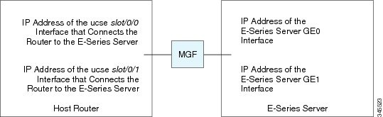
| Step 3 |
Router (config)# interface ucse slot/0 |
Enters interface configuration mode for the router’s PCIe slot/0 interface. |
||||
| Step 4 |
Enter one of the following commands:
|
The ip address command specifies the IP address of the router's internal PCIe interface that connects the router to the E-Series Server's GE0 interface. See the figure above. or The ip unnumbered command enables IP processing on an interface without assigning an explicit IP address to that interface.
|
||||
| Step 5 |
Router (config-if)# no shut |
Causes the interface to be administratively up. |
||||
| Step 6 |
Router (config-if)# end |
Exits interface configuration mode. |
||||
| Step 7 |
Use the server’s operating system to configure the E-Series Server’s GE0 interface. See the figure above. |
— |
||||
| Step 8 |
Router (config)# interface ucse slot/1 |
Enters interface configuration mode for the router’s MGF slot/1 VLAN interface. See the figure above. |
||||
| Step 9 |
Router (config-if)# switchport mode trunk |
Puts the port into permanent trunking mode. The default configuration is access mode. |
||||
| Step 10 |
Router (config-if)# [switchport trunk allowed vlan vlan-numbers] |
(Optional) Allows trunking on the specified VLANs.
|
||||
| Step 11 |
Router (config-if)# exit |
Exits interface configuration mode. |
||||
| Step 12 |
Router# configure terminal |
Enters global configuration mode on the host router. |
||||
| Step 13 |
Router (config)# interface vlan vlan-number |
Enters interface configuration mode for the specified VLAN number. |
||||
| Step 14 |
Router (config-if)# ip address vlan-ip-address subnet-mask |
Specifies the IP address for the VLAN. See the figure above.
|
||||
| Step 15 |
Router (config-if)# no shut |
Causes the interface to be administratively up. |
||||
| Step 16 |
Router (config-if)# end |
Exits interface configuration mode. |
||||
| Step 17 |
Use the server’s operating system to configure the E-Series Server’s GE1 interface. See figure above. |
— |
Example
This example shows how to configure an internal connection between the router and the E-Series Server.
 Note |
The IP addresses in this configuration example are for reference only and might not be valid. |
Router> enable
Router# configure terminal

Router(config)# interface ucse 1/0
Router(config-if)# ip address 10.0.0.1 255.0.0.0
Router(config-if)# no shut
Router(config-if)# end

Use the server’s operating system to configure the E-Series Server’s GE0 interface

Router(config)# interface ucse 1/1
Router(config-if)# switchport mode trunk
Router(config-if)# exit

Router# configure terminal
Router(config)# interface vlan 1
Router(config-if)# ip address 20.0.0.1 255.255.255.0
Router(config-if)# no shut
Router(config-if)# end

Use the server’s operating system to configure the E-Series Server’s GE1 interface.
 Feedback