- Preface
- Overview
- Installing the Server OS
- Managing Chassis and Dynamic Storage
- Managing the Server
- Viewing Server Properties
- Viewing Sensors
- Managing Remote Presence
- Managing User Accounts
- Configuring Chassis Related Settings
- Configuring Network-Related Settings
- Managing Network Adapters
- Configuring Communication Services
- Managing Certificates
- Managing Firmware
- Viewing Faults and Logs
- Server Utilities
- Troubleshooting
- BIOS Parameters by Server Model
- BIOS Token Name Comparison for Multiple Interfaces
- Index
- Viewing Network Adapter Properties
- Viewing Storage Adapter Properties
- Managing vHBAs
- Managing vNICs
- Creating Virtual Drive from Unused Physical Drives
- Creating Virtual Drive from an Existing Drive Group
- Setting a Virtual Drive to Transport Ready State
- Setting a Virtual Drive as Transport Ready
- Clearing a Virtual Drive from Transport Ready State
- Importing Foreign Configuration
- Clearing Foreign Configuration
- Clearing a Boot Drive
- Enabling JBOD Mode
- Disabling a JBOD
- Retrieving TTY Logs for a Controller
- Preparing a Drive for Removal
- Undo Preparing a Drive for Removal
- Making a Dedicated Hot Spare
- Making a Global Hot Spare
- Removing a Drive from Hot Spare Pools
- Toggling Physical Drive Status
- Setting a Physical Drive as a Controller Boot Drive
- Initializing a Virtual Drive
- Set as Boot Drive
- Editing a Virtual Drive
- Deleting a Virtual Drive
- Hiding a Virtual Drive
- Starting Learn Cycles for a Battery Backup Unit
- Viewing Storage Controller Logs
Managing Network
Adapters
This chapter includes the following sections:
- Viewing Network Adapter Properties
- Viewing Storage Adapter Properties
- Managing vHBAs
- Managing vNICs
- Managing VM FEX
- Managing Storage Adapters
- Backing Up and Restoring the Adapter Configuration
- Resetting the Adapter
Viewing Network Adapter Properties
Viewing Storage Adapter Properties
| Step 1 | In the Navigation pane, click the Storage menu. | ||||||||||||||||||||||||||||||||||||||||||||
| Step 2 | In the (Server 1) RAID controller for UCS C3X60 Storage Servers area, the Controller Info tab displays by default. | ||||||||||||||||||||||||||||||||||||||||||||
| Step 3 | In the
Work pane's
Health/Status area, review the following
information:
| ||||||||||||||||||||||||||||||||||||||||||||
| Step 4 | In the
Firmware Versions area, review the following
information:
| ||||||||||||||||||||||||||||||||||||||||||||
| Step 5 | In the
PCI Info area, review the following
information:
| ||||||||||||||||||||||||||||||||||||||||||||
| Step 6 | In the
Manufacturing Data area, review the following
information:
| ||||||||||||||||||||||||||||||||||||||||||||
| Step 7 | In the
Boot Drive area, review the following
information:
| ||||||||||||||||||||||||||||||||||||||||||||
| Step 8 | In the
Running Firmware Images area, review the
following information:
| ||||||||||||||||||||||||||||||||||||||||||||
| Step 9 | In the
Startup Firmware Images area, review the
following information:
| ||||||||||||||||||||||||||||||||||||||||||||
| Step 10 | In the
Virtual Drive Count area, review the following
information:
| ||||||||||||||||||||||||||||||||||||||||||||
| Step 11 | In the
Physical Drive Count area, review the
following information:
| ||||||||||||||||||||||||||||||||||||||||||||
| Step 12 | In the
Settings area, review the following
information:
| ||||||||||||||||||||||||||||||||||||||||||||
| Step 13 | In the
Capabilities area, review the following
information:
| ||||||||||||||||||||||||||||||||||||||||||||
| Step 14 | In the
HW Configuration area, review the following
information:
| ||||||||||||||||||||||||||||||||||||||||||||
| Step 15 | In the
Error Counters area, review the following
information:
|
Managing vHBAs
Guidelines for Managing vHBAs
When managing vHBAs, consider the following guidelines and restrictions:
-
The Cisco UCS P81E Virtual Interface Card and Cisco UCS VIC 1225 Virtual Interface Card provide two vHBAs (fc0 and fc1). You can create up to 16 additional vHBAs on these adapter cards.

Note
If Network Interface Virtualization (NIV) mode is enabled for the adapter, you must assign a channel number to a vHBA when you create it.
-
When using the Cisco UCS P81E Virtual Interface Card or Cisco UCS VIC 1225 Virtual Interface Card in an FCoE application, you must associate the vHBA with the FCoE VLAN. Follow the instructions in the Modifying vHBA Properties section to assign the VLAN.
-
After making configuration changes, you must reboot the host for settings to take effect.
Viewing vHBA Properties
| Step 1 | In the Navigation pane, click the Networking menu. | ||||||||||||||||||||||||||||||||||||||||||||
| Step 2 | In the Adapter Card pane, click the vHBAs tab. | ||||||||||||||||||||||||||||||||||||||||||||
| Step 3 | In the vHBAs pane, click fc0 or fc1. | ||||||||||||||||||||||||||||||||||||||||||||
| Step 4 | In the
General area of vHBA Properties, review the
information in the following fields:
| ||||||||||||||||||||||||||||||||||||||||||||
| Step 5 | In the
Error
Recovery area, review the information in the following fields:
| ||||||||||||||||||||||||||||||||||||||||||||
| Step 6 | In the
Fibre
Channel Interrupt area, review the information in the following
fields:
| ||||||||||||||||||||||||||||||||||||||||||||
| Step 7 | In the
Fibre
Channel Port area, review the information in the following fields:
| ||||||||||||||||||||||||||||||||||||||||||||
| Step 8 | In the
Fibre
Channel Port FLOGI area, review the information in the following
fields:
| ||||||||||||||||||||||||||||||||||||||||||||
| Step 9 | In the
Fibre
Channel Port PLOGI area, review the information in the following
fields:
| ||||||||||||||||||||||||||||||||||||||||||||
| Step 10 | In the
SCSI
I/O area, review the information in the following fields:
| ||||||||||||||||||||||||||||||||||||||||||||
| Step 11 | In the
Receive/Transmit Queues area, review the information
in the following fields:
|
Modifying vHBA Properties
| Step 1 | In the Navigation pane, click the Networking menu. | ||||||||||||||||||||||||||||||||||||||||||||
| Step 2 | In the Adapter Card pane, click the vHBAs tab. | ||||||||||||||||||||||||||||||||||||||||||||
| Step 3 | In the vHBAs pane, click fc0 or fc1. | ||||||||||||||||||||||||||||||||||||||||||||
| Step 4 | In the
General area, update the following fields:
| ||||||||||||||||||||||||||||||||||||||||||||
| Step 5 | In the
Error
Recovery area, update the following fields:
| ||||||||||||||||||||||||||||||||||||||||||||
| Step 6 | In the
Fibre
Channel Interrupt area, update the following fields:
| ||||||||||||||||||||||||||||||||||||||||||||
| Step 7 | In the
Fibre
Channel Port area, update the following fields:
| ||||||||||||||||||||||||||||||||||||||||||||
| Step 8 | In the
Fibre
Channel Port FLOGI area, update the following fields:
| ||||||||||||||||||||||||||||||||||||||||||||
| Step 9 | In the
Fibre
Channel Port PLOGI area, update the following fields:
| ||||||||||||||||||||||||||||||||||||||||||||
| Step 10 | In the
SCSI
I/O area, update the following fields:
| ||||||||||||||||||||||||||||||||||||||||||||
| Step 11 | In the
Receive/Transmit Queues area, update the following
fields:
| ||||||||||||||||||||||||||||||||||||||||||||
| Step 12 | Click Save Changes. |
Creating a vHBA
The adapter provides two permanent vHBAs. If NIV mode is enabled, you can create up to 16 additional vHBAs.
| Step 1 | In the Navigation pane, click the Networking menu. |
| Step 2 | In the Adapter Card pane, click the vHBAs tab. |
| Step 3 | In the
Host
Fibre Channel Interfaces area, choose one of these actions:
The Add vHBA dialog box appears. |
| Step 4 | In the Add vHBA dialog box, enter a name for the vHBA in the Name entry box. |
| Step 5 | Click Add vHBA. |
What to Do Next
-
Reboot the server to create the vHBA.
-
If configuration changes are required, configure the new vHBA as described in Modifying vHBA Properties.
Deleting a vHBA
| Step 1 | In the Navigation pane, click the Networking menu. | ||
| Step 2 | In the Adapter Card pane, click the vHBAs tab. | ||
| Step 3 | In the
Host
Fibre Channel Interfaces area, select a vHBA or vHBAs from the
table.
| ||
| Step 4 | Click Delete vHBAs and click OK to confirm. |
vHBA Boot Table
In the vHBA boot table, you can specify up to four LUNs from which the server can boot.
Creating a Boot Table Entry
| Step 1 | In the Navigation pane, click the Networking menu. | ||||||||||||
| Step 2 | In the Adapter Card pane, click the vHBAs tab. | ||||||||||||
| Step 3 | In the Fibre Channel Interfaces area, scroll down to the Boot Table area. | ||||||||||||
| Step 4 | Click the Add Boot Entry button to open the Add Boot Entry dialog box. | ||||||||||||
| Step 5 | In the
Add Boot
Entry dialog box, review the following information and perform the
actions specified:
|
Deleting a Boot Table Entry
| Step 1 | In the Navigation pane, click the Networking menu. |
| Step 2 | In the Adapter Card pane, click the vHBAs tab. |
| Step 3 | In the Fibre Channel Interfaces area, scroll down to the Boot Table area. |
| Step 4 | In the Boot Table area, click the entry to be deleted. |
| Step 5 | Click Delete Boot Entry and click OK to confirm. |
vHBA Persistent Binding
Persistent binding ensures that the system-assigned mapping of Fibre Channel targets is maintained after a reboot.
Viewing Persistent Bindings
| Step 1 | In the Navigation pane, click the Networking menu. | ||||||||||||||||
| Step 2 | In the Adapter Card pane, click the vHBAs tab. | ||||||||||||||||
| Step 3 | In the vHBAs pane, click fc0 or fc1. | ||||||||||||||||
| Step 4 | In the
Persistent Bindings dialog box, review the following
information:
| ||||||||||||||||
| Step 5 | Click Close. |
Rebuilding Persistent Bindings
| Step 1 | In the Navigation pane, click the Networking menu. |
| Step 2 | In the Adapter Card pane, click the vHBAs tab. |
| Step 3 | In the vHBAs pane, click fc0 or fc1. |
| Step 4 | In the Fibre Channel Interfaces area, scroll down to the Persistent Bindings area. |
| Step 5 | Click the Rebuild Persistent Bindings button. |
| Step 6 | Click OK to confirm. |
Managing vNICs
Guidelines for Managing vNICs
When managing vNICs, consider the following guidelines and restrictions:
-
The Cisco UCS P81E Virtual Interface Card and Cisco UCS VIC 1225 Virtual Interface Card provide two default vNICs (eth0 and eth1). You can create up to 16 additional vNICs on these adapter cards.
Note
If Network Interface Virtualization (NIV) mode is enabled for the adapter, you must assign a channel number to a vNIC when you create it.
-
After making configuration changes, you must reboot the host for settings to take effect.
Cisco C-series servers use Remote Direct Memory Access (RDMA) over Converged Ethernet (RoCE) for packet transfers. RoCE defines the mechanism of performing RDMA over ethernet, based on the similar mechanism of RDMA over Infiniband. However, RoCE, with its performance oriented characteristics, delivers a superior performance compared to traditional network socket implementation because of the lower latency, lower CPU utilization and higher utilization of network bandwidth. RoCE meets the requirement of moving large amount of data across networks very efficiently.
Viewing vNIC Properties
| Step 1 | In the Navigation pane, click the Networking menu. | ||||||||||||||||||||||||||||||||||||||||||||||||||||||||||||||
| Step 2 | In the Adapter Card pane, click the vNICs tab. | ||||||||||||||||||||||||||||||||||||||||||||||||||||||||||||||
| Step 3 | In the vNICs pane, click eth0 or eth1. | ||||||||||||||||||||||||||||||||||||||||||||||||||||||||||||||
| Step 4 | In the
Ethernet Interfaces pane's
vNIC
Properties area, review the information in the following fields:
| ||||||||||||||||||||||||||||||||||||||||||||||||||||||||||||||
| Step 5 | In the
Ethernet
Interrupt area, review the information in the following fields:
| ||||||||||||||||||||||||||||||||||||||||||||||||||||||||||||||
| Step 6 | In the
Ethernet
Receive Queue area, review the information in the following fields:
| ||||||||||||||||||||||||||||||||||||||||||||||||||||||||||||||
| Step 7 | In the
Ethernet
Transmit Queue area, review the information in the following
fields:
| ||||||||||||||||||||||||||||||||||||||||||||||||||||||||||||||
| Step 8 | In the
Completion Queue area, review the information in the
following fields:
| ||||||||||||||||||||||||||||||||||||||||||||||||||||||||||||||
| Step 9 | In the
TCP
Offload area, review the information in the following fields:
| ||||||||||||||||||||||||||||||||||||||||||||||||||||||||||||||
| Step 10 | In the
Receive Side Scaling area, review the information in
the following fields:
|
Modifying vNIC Properties
| Step 1 | In the Navigation pane, click the Networking menu. | ||||||||||||||||||||||||||||||||||||||||||||||||||||||||||||||
| Step 2 | In the Adapter Card pane, click the vNICs tab. | ||||||||||||||||||||||||||||||||||||||||||||||||||||||||||||||
| Step 3 | In the vNICs pane, click eth0 or eth1. | ||||||||||||||||||||||||||||||||||||||||||||||||||||||||||||||
| Step 4 | In the
Ethernet
Interfaces pane's
vNIC Properties area, update the following
fields:
| ||||||||||||||||||||||||||||||||||||||||||||||||||||||||||||||
| Step 5 | In the
Ethernet
Interrupt area, update the following fields:
| ||||||||||||||||||||||||||||||||||||||||||||||||||||||||||||||
| Step 6 | In the
Ethernet
Receive Queue area, update the following fields:
| ||||||||||||||||||||||||||||||||||||||||||||||||||||||||||||||
| Step 7 | In the
Ethernet
Transmit Queue area, update the following fields:
| ||||||||||||||||||||||||||||||||||||||||||||||||||||||||||||||
| Step 8 | In the
Completion Queue area, update the following fields:
| ||||||||||||||||||||||||||||||||||||||||||||||||||||||||||||||
| Step 9 | In the
TCP
Offload area, update the following fields:
| ||||||||||||||||||||||||||||||||||||||||||||||||||||||||||||||
| Step 10 | In the
Receive Side Scaling area, update the following
fields:
| ||||||||||||||||||||||||||||||||||||||||||||||||||||||||||||||
| Step 11 | Click Save Changes. |
Creating a vNIC
The adapter provides two permanent vNICs. You can create up to 16 additional vNICs.
| Step 1 | In the Navigation pane, click the Networking menu. | ||
| Step 2 | In the Adapter Card pane, click the vNICs tab. | ||
| Step 3 | In the
Host
Ethernet Interfaces area, choose one of these actions:
The Add vNIC dialog box appears. | ||
| Step 4 | In the Add vNIC dialog box, enter a name for the vNIC in the Name entry box. | ||
| Step 5 | (Optional)In the
Add
vNIC dialog box, enter a channel number for the vNIC in the
Channel
Number entry box.
| ||
| Step 6 | Click Add vNIC. |
What to Do Next
If configuration changes are required, configure the new vNIC as described in Modifying vNIC Properties.
Deleting a vNIC
| Step 1 | In the Navigation pane, click the Networking menu. | ||
| Step 2 | In the Adapter Card pane, click the vNICs tab. | ||
| Step 3 | In the
Host
Ethernet Interfaces area, select a vNIC from the table.
| ||
| Step 4 | Click Delete vNIC and click OK to confirm. |
Managing Cisco usNIC
Overview of Cisco usNIC
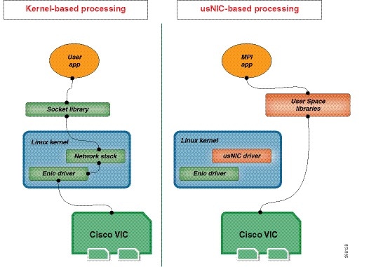
The Cisco user-space NIC (Cisco usNIC) feature improves the performance of software applications that run on the Cisco UCS servers in your data center by bypassing the kernel when sending and receiving networking packets. The applications interact directly with a Cisco UCS VIC second generation or later generation adapter, such as the , which improves the networking performance of your high-performance computing cluster. To benefit from Cisco usNIC, your applications must use the Message Passing Interface (MPI) instead of sockets or other communication APIs.
Cisco usNIC offers the following benefits for your MPI applications:
-
Provides a low-latency and high-throughput communication transport.
-
Employs the standard and application-independent Ethernet protocol.
-
Takes advantage of lowlatency forwarding, Unified Fabric, and integrated management support in the following Cisco data center platforms:
Standard Ethernet applications use user-space socket libraries, which invoke the networking stack in the Linux kernel. The networking stack then uses the Cisco eNIC driver to communicate with the Cisco VIC hardware. The following figure shows the contrast between a regular software application and an MPI application that uses Cisco usNIC.
Viewing and Configuring Cisco usNIC using the Cisco IMC GUI
You must log in to the Cisco IMC GUI with administrator privileges to perform this task. Click Play on this video to watch how to configure Cisco usNIC in CIMC.
| Step 1 | Log into the
Cisco IMC
GUI.
For more information about how to log into Cisco IMC, see Cisco UCS C-Series Servers Integrated Management Controller GUI Configuration Guide. | ||||||||||||||||||||||||||||||||||||||
| Step 2 | In the Navigation pane, click the Networking menu. | ||||||||||||||||||||||||||||||||||||||
| Step 3 | In the Adapter Card pane, click the vNICs tab. | ||||||||||||||||||||||||||||||||||||||
| Step 4 | In the vNICs pane, click eth0 or eth1. | ||||||||||||||||||||||||||||||||||||||
| Step 5 | In the Ethernet Interfaces area, select the usNIC area. | ||||||||||||||||||||||||||||||||||||||
| Step 6 | In the
Properties area, review and update the following
fields:
| ||||||||||||||||||||||||||||||||||||||
| Step 7 | Click
Save
Changes.
The changes take effect upon the next server reboot. |
Viewing usNIC Properties
| Step 1 | In the Navigation pane, click the Networking menu. | ||||||||||||||||||||||||||||||||||||||
| Step 2 | In the Adapter Card pane, click the vNICs tab. | ||||||||||||||||||||||||||||||||||||||
| Step 3 | In the vNICs pane, click eth0 or eth1. | ||||||||||||||||||||||||||||||||||||||
| Step 4 | In the
Host Ethernet Interfaces pane's
usNIC Properties area, review the information
in the following fields:
|
Configuring iSCSI Boot Capability
Configuring iSCSI Boot Capability for vNICs
When the rack-servers are configured in a standalone mode, and when the VIC adapters are directly attached to the Nexus 5000 and Nexus 6000 family of switches, you can configure these VIC adapters to boot the servers remotely from iSCSI storage targets. You can configure Ethernet vNICs to enable a rack server to load the host OS image from remote iSCSI target devices.
To configure the iSCSI boot capability on a vNIC:
-
You must log in with admin privileges to perform this task.
-
To configure a vNIC to boot a server remotely from an iSCSI storage target, you must enable the PXE boot option on the vNIC.
Note | You can configure a maximum of 2 iSCSI vNICs for each host. |
Configuring iSCSI Boot Capability on a vNIC
You can configure a maximum of 2 iSCSI vNICs for each host.
| Step 1 | In the Navigation pane, click the Networking menu. | ||||||||||||||||||||||||
| Step 2 | In the Adapter Card pane, click the vNICs tab. | ||||||||||||||||||||||||
| Step 3 | In the vNICs pane, click eth0 or eth1. | ||||||||||||||||||||||||
| Step 4 | In the Ethernet Interfaces area, select the iSCSI Boot Properties area. | ||||||||||||||||||||||||
| Step 5 | In the
General
Area, update the following fields:
| ||||||||||||||||||||||||
| Step 6 | In the
Initiator Area, update the following fields:
| ||||||||||||||||||||||||
| Step 7 | In the
Primary
Target Area, update the following fields:
| ||||||||||||||||||||||||
| Step 8 | In the
Secondary Target Area, update the following fields:
| ||||||||||||||||||||||||
| Step 9 | Click Save Changes. |
Removing iSCSI Boot Configuration from a vNIC
You must log in with admin privileges to perform this task.
| Step 1 | In the Navigation pane, click the Networking menu. |
| Step 2 | In the Adapter Card pane, click the vNICs tab. |
| Step 3 | In the vNICs pane, click eth0 or eth1. |
| Step 4 | In the Ethernet Interfaces area, select the iSCSI Boot Properties area. |
| Step 5 | Click the Unconfigure ISCSI button at the bottom of the area. |
Managing VM FEX
Virtual Machine Fabric Extender
Cisco Virtual Machine Fabric Extender (VM FEX) extends the (prestandard) IEEE 802.1Qbh port extender architecture to virtual machines. In this architecture, each VM interface is provided with a virtual Peripheral Component Interconnect Express (PCIe) device and a virtual port on a switch.
For this release, VM FEX supports the following cards and Operating systems:
Cards - Cisco UCS 1225 Virtual Interface Card
VM FEX is not supported on Microsoft Hyper-V and Red Hat KVM for this release.
Viewing Virtual FEX Properties
| Step 1 | In the Navigation pane, click the Networking menu. | ||||||||||||||||||
| Step 2 | In the Adapter Card pane, click the VM FEXs tab. | ||||||||||||||||||
| Step 3 | In the
Virtual FEXs area, review the following
information:
| ||||||||||||||||||
| Step 4 | In the Virtual FEXs area, select a VM FEX from the table. | ||||||||||||||||||
| Step 5 | Click Properties to open the VM FEX Properties dialog box for the selected VM FEX. | ||||||||||||||||||
| Step 6 | In the
General
Properties area, review the information in the following fields:
| ||||||||||||||||||
| Step 7 | In the
Ethernet
Interrupt area, review the information in the following fields:
| ||||||||||||||||||
| Step 8 | In the
Ethernet
Receive Queue area, review the information in the following fields:
| ||||||||||||||||||
| Step 9 | In the
Ethernet
Transmit Queue area, review the information in the following fields:
| ||||||||||||||||||
| Step 10 | In the
Completion Queue area, review the information in the
following fields:
| ||||||||||||||||||
| Step 11 | In the
TCP
Offload area, review the information in the following fields:
| ||||||||||||||||||
| Step 12 | In the
Receive
Side Scaling area, review the information in the following fields:
|
Managing Storage Adapters
Creating Virtual Drive from Unused Physical Drives
You must log in with admin privileges to perform this task.
| Step 1 | In the Navigation pane, click the Storage menu. | ||||||||||||||||||
| Step 2 | On the Storage tab, click the Server 1 tab (RAID controller for UCS 3x60 Storage servers (SLOT-MEZZ)) . | ||||||||||||||||||
| Step 3 | In the
Actions area, click
Create
Virtual Drive from Unused Physical Drives.
The Create Virtual Drive from Unused Physical Drives dialog box displays. | ||||||||||||||||||
| Step 4 | In the
Create
Virtual Drive from Unused Physical Drives dialog box, select the
RAID level for the new virtual drives:
This can be one of the following: | ||||||||||||||||||
| Step 5 | In the
Create
Drive Groups area, choose one or more physical drives to include in
the group.
Use the >> button to add the drives to the Drive Groups table. Use the << button to remove physical drives from the drive group.
| ||||||||||||||||||
| Step 6 | In the
Virtual
Drive Properties area, update the following properties:
| ||||||||||||||||||
| Step 7 | Click the Generate XML API Request button to generate an API request. | ||||||||||||||||||
| Step 8 | Click Close. | ||||||||||||||||||
| Step 9 | Click Create Virtual Drive. |
Creating Virtual Drive from an Existing Drive Group
You must log in with admin privileges to perform this task.
| Step 1 | In the Navigation pane, click the Storage menu. | ||||||||||||||||||
| Step 2 | On the Storage tab, click the Server 1 tab with the appropriate LSI MegaRAID controller. | ||||||||||||||||||
| Step 3 | In the
Actions area, click
Create
Virtual Drive from an Existing Virtual Drive Group.
The Create Virtual Drive from an Existing Virtual Drive Group dialog box displays. | ||||||||||||||||||
| Step 4 | In the Create Virtual Drive from an Existing Virtual Drive Group dialog box, select the virtual drive whose drive group you want to use to create a new virtual drive. | ||||||||||||||||||
| Step 5 | In the
Virtual
Drive Properties area, update the following properties:
| ||||||||||||||||||
| Step 6 | Click the Generate XML API Request button to generate an API request. | ||||||||||||||||||
| Step 7 | Click Close. | ||||||||||||||||||
| Step 8 | Click Create Virtual Drive. |
Setting a Virtual Drive to Transport Ready State
You can move a virtual drive from one MegaRAID controller to another using the Set Transport Ready feature. This allows all the pending IOs of the virtual drive to complete their activities, hide the virtual drive from the operating system, flush cache, pause all the background operations, and save the current progress in disk data format, allowing you to move the drive. When you move a virtual drive, all other drives belonging to the same drive group inherit the same change as the moved drive.
When the last configured physical drive on the group is removed from the current controller, the drive group becomes foreign and all foreign configuration rules apply to the group. However, the Transport Ready feature does not change any foreign configuration behavior.
You can also clear a virtual drive from the Transport Ready state. This makes the virtual drive available to the operating systems.
-
Only a maximum of 16 transport ready drive groups are currently supported.
-
This feature is not supported on high availability.
-
A virtual drive cannot be set as transport ready under these conditions: -
When a virtual drive of a drive group is being reconstructed
-
When a virtual drive of a drive group contains a pinned cache
-
When a virtual drive of a drive group is marked as cacheable or associated with a cachecade virtual drive
-
If a virtual drive is a cachecade virtual drive
-
If a virtual drive is offline
-
If a virtual drive is a bootable virtual drive
-
Setting a Virtual Drive as Transport Ready
| Step 1 | In the Navigation pane, click the Storage menu. | ||||||||||
| Step 2 | On the Storage menu, click the appropriate LSI MegaRAID or HBA Controller. | ||||||||||
| Step 3 | On the Work pane, click the Virtual Drive Info tab. | ||||||||||
| Step 4 | In the Virtual Drives area, choose the drive that you want set as transport ready. | ||||||||||
| Step 5 | In the
Actions area, click
Set
Transport Ready.
The Set Transport Ready dialog box displays. | ||||||||||
| Step 6 | Update the
following properties in the dialog box:
|
Clearing a Virtual Drive from Transport Ready State
| Step 1 | In the Navigation pane, click the Storage menu. |
| Step 2 | On the Storage menu, click the appropriate LSI MegaRAID or HBA controller. |
| Step 3 | On the Work pane, click the Virtual Drive Info tab. |
| Step 4 | In the Virtual Drives area, choose the drive to set as transport ready. |
| Step 5 | In the
Actions area, click
Clear
Transport Ready.
This reverts the selected transport ready virtual drive to its original optimal state. |
Importing Foreign Configuration
When one or more physical drives that have previously been configured with a different controller are inserted into a server, they are identified as foreign configurations. You can import these foreign configurations to a controller.
You must log in with admin privileges to perform this task.
Clearing Foreign Configuration
This task clears all foreign configuration on the controller. Also, all configuration information from all physical drives hosting foreign configuration is deleted. This action cannot be reverted.
You must log in with admin privileges to perform this task.
Clearing a Boot Drive
This task clears the boot drive configuration on the controller. This action cannot be reverted.
You must log in with admin privileges to perform this task.
Enabling JBOD Mode
| Step 1 | In the Navigation pane, click the Storage menu. |
| Step 2 | On the Storage tab, click the Server 1 tab with the appropriate LSI MegaRAID Controller. |
| Step 3 | In the Work pane, click the Physical Drive Info tab. |
| Step 4 | In the Physical Drives area, select an unconfigured good drive. |
| Step 5 | In the Actions area, click Enable JBOD. |
| Step 6 | Click Ok to confirm. |
Disabling a JBOD
Note | This option is available only on some UCS C-Series servers. |
JBOD option must be enabled for the selected controller.
| Step 1 | In the Navigation pane, click the Storage menu. |
| Step 2 | On the Storage menu, click the Server 1 tab with the appropriate LSI MegaRAID Controller. |
| Step 3 | On the Work pane, click Physical Drive Info tab. |
| Step 4 | In the Physical Drives area, select a JBOD drive. |
| Step 5 | In the Actions area, click Disable JBOD. |
| Step 6 | Click Ok to confirm. |
Retrieving TTY Logs for a Controller
This task retrieves the TTY logs for the controller and places it in the /var/log location. This ensures that this log data is available when Technical Support Data is requested.
You must log in with admin privileges to perform this task.
| Step 1 | In the Navigation pane, click the Storage menu. |
| Step 2 | In the (Server 1) RAID controller for UCS C3X60 Storage Servers area, the Controller Info tab displays by default. |
| Step 3 | In the Actions area, click Get TTY Log. |
| Step 4 | Click
OK to confirm.
Retrieving TTY logs for a controller could take up to 2-4 minutes. Until this process is complete, do not initiate exporting technical support data. |
Preparing a Drive for Removal
Note | You can perform this task only on physical drives that display the Unconfigured Good status. |
You must log in with admin privileges to perform this task.
| Step 1 | In the Navigation pane, click the Storage menu. |
| Step 2 | On the Storage menu, click the Server 1 tab with the appropriate LSI MegaRAID Controller. |
| Step 3 | On the Work pane, click the Physical Drive Info tab. |
| Step 4 | In the Physical Drives area, select the drive you want to remove. |
| Step 5 | In the Actions area, click Prepare for Removal. |
| Step 6 | Click OK to confirm. |
Undo Preparing a Drive for Removal
You must log in with admin privileges to perform this task.
| Step 1 | In the Navigation pane, click the Storage menu. |
| Step 2 | On the Storage menu, click the Server 1 tab with the appropriate LSI MegaRAID Controller. |
| Step 3 | On the Work pane, click the Physical Drive Info tab. |
| Step 4 | In the Physical Drives area, select a drive with a status of Ready to Remove. |
| Step 5 | In the Actions area, click Undo Prepare for Removal. |
| Step 6 | Click OK to confirm. |
Making a Dedicated Hot Spare
You must log in with admin privileges to perform this task.
| Step 1 | In the Navigation pane, click the Storage tab. | ||||||||||
| Step 2 | On the Storage menu, click the Server 1 tab with the appropriate LSI MegaRAID Controller. | ||||||||||
| Step 3 | On the Work pane, click the Physical Drive Info tab. | ||||||||||
| Step 4 | In the Physical Drives area, select an unconfigured good drive you want to make a dedicated hot spare. | ||||||||||
| Step 5 | In the
Actions area, click
Make
Dedicated Hot Spare.
The Make Dedicated Hot Spare dialog box displays. | ||||||||||
| Step 6 | In the
Virtual
Drive Details area, update the following properties:
| ||||||||||
| Step 7 | Click Make Dedicated Hot Spare to confirm. |
Making a Global Hot Spare
You must log in with admin privileges to perform this task.
| Step 1 | In the Navigation pane, click the Storage tab. |
| Step 2 | On the Storage menu, click the Server 1 tab with the appropriate LSI MegaRAID Controller. |
| Step 3 | On the Work pane, click the Physical Drive Info tab. |
| Step 4 | In the Physical Drives area, select an unconfigured good drive you want to make a global hot spare. |
| Step 5 | In the Actions area, click Make Global Hot Spare. |
Removing a Drive from Hot Spare Pools
You must log in with admin privileges to perform this task.
| Step 1 | In the Navigation pane, click the Storage menu. |
| Step 2 | On the Storage tab, click the appropriate LSI MegaRAID controller. |
| Step 3 | On the Work pane, click the Physical Drive Info tab. |
| Step 4 | In the Physical Drives area, select the global or dedicated hot spare you want to remove from the hot spare pools. |
| Step 5 | In the Actions area, click Remove From Hot Spare Pools. |
Toggling Physical Drive Status
| Step 1 | In the Navigation pane, click the Storage tab. |
| Step 2 | On the Storage menu, click the Server 1 tab with the appropriate LSI MegaRAID Controller. |
| Step 3 | On the Work pane, click the Physical Drive Info tab. |
| Step 4 | In the Physical Drives area, select the drive you want to set as unconfigured good. |
| Step 5 | In the Actions area, click Set State as Unconfigured Good. |
| Step 6 | Click
OK to confirm that the JBOD mode be disabled.
The Set State as JBOD option is enabled. |
| Step 7 | To enable the JBOD mode for the physical drive, click Set State as JBOD. |
| Step 8 | Click
OK to confirm.
The Set State as Unconfigured Good option is enabled. |
Setting a Physical Drive as a Controller Boot Drive
| Step 1 | In the Navigation pane, click the Storage menu. |
| Step 2 | On the Storage menu, click the Server 1 tab with the appropriate LSI MegaRAID Controller. |
| Step 3 | On the Work pane, click the Physical Drive Info tab. |
| Step 4 | In the Physical Drives area, select the drive you want to set as boot drive for the controller. |
| Step 5 | In the Actions area, click Set as Boot Drive. |
| Step 6 | Click OK to confirm. |
Initializing a Virtual Drive
All data on a virtual drive is lost when you initialize the drive. Before you run an initialization, back up any data on the virtual drive that you want to save.
You must log in with admin privileges to perform this task.
| Step 1 | In the Navigation pane, click the Storage menu. | ||||||||
| Step 2 | On the Storage menu, click the Server 1 tab with the appropriate LSI MegaRAID Controller. | ||||||||
| Step 3 | On the Work pane, click the Virtual Drive Info tab. | ||||||||
| Step 4 | In the Virtual Drives area, choose the drive that you want to initialize. | ||||||||
| Step 5 | In the
Actions area, click
Initialize.
The Initialize Virtual Drive dialog box displays. | ||||||||
| Step 6 | Choose the type
of initialization you want to use for the virtual drive.
This can be one of the following: | ||||||||
| Step 7 | Click Initialize VD to initialize the drive, or Cancel to close the dialog box without making any changes. | ||||||||
| Step 8 | To view the
status of the task running on the drive, in the
Operations area, click
Refresh.
The following details are displayed:
|
Set as Boot Drive
You must log in with admin privileges to perform this task.
| Step 1 | In the Navigation pane, click the Storage menu. |
| Step 2 | On the Storage menu, click the Server 1 tab with the appropriate LSI MegaRAID Controller. |
| Step 3 | On the Work pane, click the Virtual Drive Info tab. |
| Step 4 | In the Virtual Drives area, choose the drive from which the controller must boot. |
| Step 5 | In the Actions area, click Set as Boot Drive. |
| Step 6 | Click OK to confirm. |
Editing a Virtual Drive
| Step 1 | In the Navigation pane, click the Storage menu. | ||||||
| Step 2 | On the Storage menu, click the Server 1 tab with the appropriate LSI MegaRAID Controller. | ||||||
| Step 3 | On the Work pane, click Virtual Drive Info tab. | ||||||
| Step 4 | In the Virtual Drives area, click Edit Virtual Drive. | ||||||
| Step 5 | Review the instructions, and then click OK. The Edit Virtual Drive dialog box displays before prompting you to take a backup of your data. | ||||||
| Step 6 | From the
Select
RAID Level to migrate drop-down list, choose a RAID level.
See the following table for RAID migration criteria:
| ||||||
| Step 7 | From the
Write
Policy drop-down list in the
Virtual
Drive Properties area, choose one of the following:
| ||||||
| Step 8 | Click Save Changes. |
Deleting a Virtual Drive
This task deletes a virtual drive, including the drives that run the booted operating system. So back up any data that you want to retain before you delete a virtual drive.
You must log in with admin privileges to perform this task.
| Step 1 | In the Navigation pane, click the Storage menu. |
| Step 2 | On the Storage menu, click the Server 1 tab with the appropriate LSI MegaRAID Controller. |
| Step 3 | On the Work pane, click the Virtual Drive Info tab. |
| Step 4 | In the Virtual Drives area, select the virtual drive you want to delete. |
| Step 5 | In the Actions area, click Delete Virtual Drive. |
| Step 6 | Click OK to confirm. |
Hiding a Virtual Drive
You must log in with admin privileges to perform this task.
| Step 1 | In the Navigation pane, click the Storage menu. |
| Step 2 | On the Storage menu, click the Server 1 tab (RAID controller for UCS C3X60 Storage Servers (SLOT-MEZZ)). |
| Step 3 | On the Work pane, click the Virtual Drive Info tab. |
| Step 4 | In the Virtual Drives area, select the virtual drive you want to hide. |
| Step 5 | In the Actions area, click Hide Drive. |
| Step 6 | Click OK to confirm. |
Starting Learn Cycles for a Battery Backup Unit
You must log in with admin privileges to perform this task.
| Step 1 | In the Navigation pane, click the Storage menu. |
| Step 2 | On the Storage menu, click the Server 1 tab with the appropriate LSI MegaRAID Controller. |
| Step 3 | On the Work pane, click the Battery Backup Unit tab. |
| Step 4 | From the
Actions pane, click
Start
Learn Cycle.
A dialog prompts you to confirm the task. |
| Step 5 | Click OK. |
Viewing Storage Controller Logs
You must log in with admin privileges to perform this task.
| Step 1 | In the Navigation pane, click the Storage menu. | ||||||||
| Step 2 | On the Storage menu, click the Server 1 tab with the appropriate LSI MegaRAID Controller. | ||||||||
| Step 3 | On the
Work pane, click
Storage
Log tab and review the following information:
|
Backing Up and Restoring the Adapter Configuration
Exporting the Adapter Configuration
The adapter configuration can be exported as an XML file to a remote server which can be one of the following:
Obtain the remote server IP address.
| Step 1 | In the Navigation pane, click the Networking menu. | ||||||||||||||
| Step 2 | Click the
Adapter Card tab.
The General tab appears. | ||||||||||||||
| Step 3 | In the
Actions area of the
General tab, click
Export
Configuration.
The Export Adapter Configuration dialog box opens. | ||||||||||||||
| Step 4 | In the
Export
Adapter Configuration dialog box, update the following fields:
| ||||||||||||||
| Step 5 | Click Export Configuration. |
Importing the Adapter Configuration
| Step 1 | In the Navigation pane, click the Networking menu. | ||||||||||||||
| Step 2 | Click the
Adapter Card tab.
The General tab appears. | ||||||||||||||
| Step 3 | In the
Actions area of the
General tab, click
Import
Configuration.
The Import Adapter Configuration dialog box opens. | ||||||||||||||
| Step 4 | In the
Import
Adapter Configuration dialog box, update the following fields:
| ||||||||||||||
| Step 5 | Click Import Configuration. The adapter downloads the configuration file from the specified path on the TFTP server at the specified IP address. The configuration will be installed during the next server reboot. |
What to Do Next
Reboot the server to apply the imported configuration.
Restoring Adapter Defaults
| Step 1 | In the Navigation pane, click the Networking menu. | ||
| Step 2 | Click the
Adapter
Card tab.
The General tab appears. | ||
| Step 3 | In the
Actions area of the
General tab, click
Reset To
Defaults and click
OK to confirm.
|
 Feedback