VersaStack with Cisco UCS Mini and IBM V5000 2nd Generation Design Guide
Available Languages

VersaStack with Cisco UCS Mini and IBM V5000 2nd Generation Design Guide
Design Guide for VersaStack with Cisco UCS Mini, IBM Storwize V5000 2nd Generation and VMware vSphere 6.0 U2
Last Updated: December 21, 2016

The CVD program consists of systems and solutions designed, tested, and documented to facilitate faster, more reliable, and more predictable customer deployments. For more information visit
http://www.cisco.com/go/designzone.
ALL DESIGNS, SPECIFICATIONS, STATEMENTS, INFORMATION, AND RECOMMENDATIONS (COLLECTIVELY, "DESIGNS") IN THIS MANUAL ARE PRESENTED "AS IS," WITH ALL FAULTS. CISCO AND ITS SUPPLIERS DISCLAIM ALL WARRANTIES, INCLUDING, WITHOUT LIMITATION, THE WARRANTY OF MERCHANTABILITY, FITNESS FOR A PARTICULAR PURPOSE AND NONINFRINGEMENT OR ARISING FROM A COURSE OF DEALING, USAGE, OR TRADE PRACTICE. IN NO EVENT SHALL CISCO OR ITS SUPPLIERS BE LIABLE FOR ANY INDIRECT, SPECIAL, CONSEQUENTIAL, OR INCIDENTAL DAMAGES, INCLUDING, WITHOUT LIMITATION, LOST PROFITS OR LOSS OR DAMAGE TO DATA ARISING OUT OF THE USE OR INABILITY TO USE THE DESIGNS, EVEN IF CISCO OR ITS SUPPLIERS HAVE BEEN ADVISED OF THE POSSIBILITY OF SUCH DAMAGES.
THE DESIGNS ARE SUBJECT TO CHANGE WITHOUT NOTICE. USERS ARE SOLELY RESPONSIBLE FOR THEIR APPLICATION OF THE DESIGNS. THE DESIGNS DO NOT CONSTITUTE THE TECHNICAL OR OTHER PROFESSIONAL ADVICE OF CISCO, ITS SUPPLIERS OR PARTNERS. USERS SHOULD CONSULT THEIR OWN TECHNICAL ADVISORS BEFORE IMPLEMENTING THE DESIGNS. RESULTS MAY VARY DEPENDING ON FACTORS NOT TESTED BY CISCO.
CCDE, CCENT, Cisco Eos, Cisco Lumin, Cisco Nexus, Cisco StadiumVision, Cisco TelePresence, Cisco WebEx, the Cisco logo, DCE, and Welcome to the Human Network are trademarks; Changing the Way We Work, Live, Play, and Learn and Cisco Store are service marks; and Access Registrar, Aironet, AsyncOS, Bringing the Meeting To You, Catalyst, CCDA, CCDP, CCIE, CCIP, CCNA, CCNP, CCSP, CCVP, Cisco, the Cisco Certified Internetwork Expert logo, Cisco IOS, Cisco Press, Cisco Systems, Cisco Systems Capital, the Cisco Systems logo, Cisco Unity, Collaboration Without Limitation, EtherFast, EtherSwitch, Event Center, Fast Step, Follow Me Browsing, FormShare, GigaDrive, HomeLink, Internet Quotient, IOS, iPhone, iQuick Study, IronPort, the IronPort logo, LightStream, Linksys, MediaTone, MeetingPlace, MeetingPlace Chime Sound, MGX, Networkers, Networking Academy, Network Registrar, PCNow, PIX, PowerPanels, ProConnect, ScriptShare, SenderBase, SMARTnet, Spectrum Expert, StackWise, The Fastest Way to Increase Your Internet Quotient, TransPath, WebEx, and the WebEx logo are registered trademarks of Cisco Systems, Inc. and/or its affiliates in the United States and certain other countries.
All other trademarks mentioned in this document or website are the property of their respective owners. The use of the word partner does not imply a partnership relationship between Cisco and any other company. (0809R)
© 2016 Cisco Systems, Inc. All rights reserved.
VersaStack Direct Attached SAN storage with Cisco UCS Mini and IBM Storwize V5030 Architecture
VersaStack IP-Based storage with Cisco UCS Mini and IBM Storwize V5030 Architecture
Cisco Unified Computing System
Cisco UCS 5108 Blade Server Chassis
Cisco UCS 6324 Fabric Interconnect
Cisco UCS B200 M4 Blade Servers
Cisco UCS C220 M4 Rack Servers
Cisco UCS new features specified in this design
Cisco Nexus 9000 Series Switch
IBM Storwize V5000 2nd Generation
Cisco Unified Computing System Manager
UCS Manager (Mini) Management with UCS Central
IBM Spectrum Virtualize Easy-to-Use Management GUI
Cisco Virtual Switch Update Manager (Optional)
Direct Attached Design with Fibre Channel based SAN Storage
IP-Based Design using iSCSI Storage
VersaStack with UCS Mini Network Connectivity
Cisco Nexus 9000-Series Switches vPC Best Practices
IBM Storwize V5000 2nd Generation
IBM Storwize V5030 Direct Attached SAN connectivity to Cisco UCS Mini
IBM Storwize V5030 Network Connectivity for iSCSI Storage access.
Cisco UCS C-series Server Connectivity
Compute and Storage Scalability
Hardware and Software Revisions
Cisco® Validated Designs include systems and solutions that are designed, tested, and documented to facilitate and improve customer deployments. These designs incorporate a wide range of technologies and products into a portfolio of solutions that have been developed to address the business needs of customers.
VersaStackTM is predesigned, integrated platform architecture for the data center that is built on the Cisco Unified Computing System (Cisco UCS), the Cisco Nexus® family of switches, and IBM storage arrays. VersaStack is designed with no single point of failure and with a focus on simplicity, efficiency, and versatility. VersaStack is a suitable platform for running a variety of virtualization hypervisors as well as bare metal operating systems to support enterprise workloads.
VersaStack delivers a baseline configuration and also has the flexibility to be sized and optimized to accommodate many different use cases and requirements. System designs discussed in this document have been validated for resiliency by subjecting to multiple failure conditions while under load. Fault tolerance to operational tasks such as firmware and operating system upgrades, switch, cable and hardware failures, and loss of power has also been ascertained.
This VersaStack solution was designed to address the IT infrastructure requirements of mid-sized enterprises, smaller IT and ROBO (remote office and branch office) environments. These deployments support a diverse set of applications and typically have access to a very limited IT staff and budget. As such, simplicity and ease of deployment and management are critical factors when selecting an infrastructure platform to address IT needs.
This VersaStack incorporates Cisco UCS Mini and IBM V5000 into a single, flexible architecture and describes a solution with VMware vSphere 6.0 Update 2 built on the VersaStack with block storage. The document discusses design choices made and best practices followed in deploying the shared infrastructure platform.
Introduction
Industry trends indicate a vast data center transformation toward converged solutions and cloud computing. Enterprise customers are moving away from disparate layers of compute, network and storage to integrated stacks providing the basis for a more cost-effective virtualized environment that can lead to cloud computing for increased agility and reduced cost.
By integrating standards based components that are compatible, scalable and easy to use, VersaStack addresses customer issues during the planning, design and implementation stages. When deployed, the efficient and intuitive front-end tools provide the means to manage the platform in an easy and agile manner. The VersaStack architecture thus mitigates customer risk and eliminates critical pain points while providing necessary guidance and measurable value. The result is a consistent platform with characteristics to meet changing workloads of any customer.
In this document we will describe a reference architecture detailing a Virtual Server Infrastructure with VMware vSphere 6.0 U2 Hypervisor, Cisco UCS Compute and IBM Storwize V5030 Storage array.
The VersaStack IP-Based Design covered in this document highlights an alternative, supported, design option. The IP-Based design in not validated as part of the VersaStack with Cisco UCS Mini and IBM V5000 2nd Generation Design Guide CVD. For a validated IP-Based Deployment Guide, please refer to the V5000 1st Generation storage Deployment Guide at: www.cisco.com/c/en/us/td/docs/unified_computing/ucs/UCS_CVDs/Versastack_n5k_mini.html
Audience
The intended audience of this document includes, but is not limited to, sales engineers, field consultants, professional services, IT managers, partner engineering, and customers who want to take advantage of an infrastructure built to deliver IT efficiency and enable IT innovation.
What’s New?
The following design elements distinguish this version of VersaStack from previous models:
· Validation of the Cisco UCS Mini with Cisco Nexus 9000 switches and IBM Storwize V5000 2nd Generation storage array
· Support for the Cisco UCS 3.1(2c) release
· Cisco UCS Mini with Secondary Chassis support
· Support for release 7.7.1.3 of IBM® Spectrum Virtualize™
For more information on previous VersaStack models, please refer the VersaStack guides at:
Cisco and IBM have thoroughly validated and verified the VersaStack solution architecture and its many use cases while creating a portfolio of detailed documentation, information, and references to assist customers in transforming their data centers to this shared infrastructure model. This portfolio will include, but is not limited to the following items:
· Best practice architectural design
· Workload sizing and scaling guidance
· Implementation and deployment instructions
· Technical specifications (rules for what is, and what is not, a VersaStack configuration)
· Frequently asked questions (FAQs)
· Cisco Validated Designs (CVDs) and IBM Redbooks focused on a variety of use cases
Cisco and IBM have also built a robust and experienced support team focused on VersaStack solutions, from customer account and technical sales representatives to professional services and technical support engineers. The support alliance provided by IBM and Cisco provides customers and channel services partners with direct access to technical experts who collaborate with cross vendors and have access to shared lab resources to resolve potential issues.
VersaStack supports tight integration with hypervisors leading to virtualized environments and cloud infrastructures, making it the logical choice for long-term investment. Table 1 lists the features in VersaStack:
Table 1 VersaStack Component Features
| IBM® Spectrum Virtualize™ 7.7.1.3 with V5000 |
Cisco UCS and Cisco Nexus 9000 Switches |
| Unified Fabric |
|
| HyperSwap® |
Virtualized IO |
| Software Compression (V5030) and Encryption (V5020 and V5030) |
Extended Memory |
| NPIV host port fabric virtualization |
Stateless Servers through policy based management |
| External virtualization (V5030) |
Centralized Management |
| IBM FlashCopy, Metro Mirror and Global Mirror |
Investment Protection |
| Distributed RAID |
Scalability |
| VMware Virtual Volumes |
Automation |
VersaStack provides a uniform approach to IT architecture, offering a well-characterized and documented shared pool of resources for application workloads. VersaStack delivers operational efficiency and consistency with the versatility to meet a variety of SLAs and IT initiatives, including:
· Application rollouts or application migrations
· Business continuity/disaster recovery
· Desktop virtualization
· Cloud delivery models (public, private, hybrid) and service models (IaaS, PaaS, SaaS)
· Asset consolidation and virtualization
VersaStack is a best practice data center architecture that includes the following infrastructure components for compute, network and storage:
· Cisco Unified Computing System (Cisco UCS)
· Cisco Nexus and MDS switches
· IBM SAN Volume Controller, IBM FlashSystem and IBM Storwize family storage
Figure 1 VersaStack Components

These components are connected and configured according to best practices of both Cisco and IBM and provide the ideal platform for running a variety of enterprise workloads with confidence.
The reference architecture covered in this document leverages the Cisco Nexus 9000 for switching, Cisco UCS Mini platform for the Compute and IBM Storwize V5000 2nd Generation Storage. VersaStack can scale up for greater performance and capacity (adding compute, network, or storage resources individually as needed), or it can scale out for environments that need multiple consistent deployments (rolling out additional VersaStack stacks).
One of the key benefits of VersaStack is the ability to maintain consistency at scale. Each of the component families shown in Figure 1 (Cisco Unified Computing System, Cisco Nexus, and IBM storage arrays) offers platform and resource options to scale the infrastructure up or down, while supporting the same features and functionality that are required under the configuration and connectivity best practices of VersaStack.
This design guide covers two unique storage configuration options, Option 1 is validated as part of this CVD effort and Option 2 is an alternative design fully supported but not validated with this effort:
· Option 1 - Utilizes IBM Storwize V5030 to support a Direct Attached Fibre Channel storage design.
· Option 2 - Utilizes IBM Storwize V5030 to support an iSCSI based IP-only storage design.
VersaStack Direct Attached SAN storage with Cisco UCS Mini and IBM Storwize V5030 Architecture
VersaStack Direct Attached SAN storage design provides a high redundancy, high-performance solution for the deployment of virtualized data center architecture. This solution design leverages Direct Attached Fibre Channel storage connectivity for compute enabling a simple, flexible and cost-effective solution.
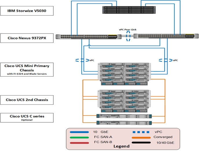
Figure 2 illustrates the use of directly attaching IBM Storwize V5030 storage controller to the Cisco UCS Mini environment. Cisco UCS Mini supports directly attached IBM storage to the integrated Cisco UCS 6324 Fabric Interconnects. This removes the requirement to have a dedicated FC switching environment, as all SAN switching and zoning functions are performed by the Cisco UCS 6324 Fabric Interconnect and managed through the Cisco UCS Manager. SAN A and B best practices are honored and ALUA enabled host based multi-pathing allow for redundant and optimal 8Gbps Fibre Channel paths into the IBM storage node canisters. This model supports only Fibre Channel access to storage. Scalability is achieved by adding storage capacity (disk expansion enclosures) to an existing V5030 storage controller, adding an additional V5030 storage controller and by adding 2nd UCS Mini chassis and/or UCS C-Series servers.
Figure 2 VersaStack Direct Attached SAN Storage Architecture

VersaStack IP-Based storage with Cisco UCS Mini and IBM Storwize V5030 Architecture
The VersaStack IP-Based Storage with UCS Mini and IBM Storwize V5030 iSCSI storage is an end-to-end IP-Based storage solution that supports SAN access using iSCSI. The solution provides a 10GbE enabled, 40Gbps capable fabric defined by Ethernet uplinks from the Cisco UCS Fabric Interconnects and IBM storage devices connected to the Cisco Nexus switches. The VersaStack design does not employ a dedicated SAN switching environment and requires no direct Fibre Channel connectivity, as iSCSI is the SAN protocol leveraged.
Figure 3, details the VersaStack architecture with Cisco UCS Mini and IP-based storage. This design uses the Cisco Nexus 9000 in standalone mode with IBM Storwize V5000 storage systems. As the illustration shows, the design is fully redundant in the compute, network, and storage layers.
The IBM Storwize V5030 system is redundantly connected to the Nexus fabric using 10Gbps links, with each node having connectivity to both the switches. Port aggregation provides improved aggregate bandwidth and link resiliency between the UCS Mini Fabric Interconnects and the Nexus 9000 switches to support application and storage traffic.
Figure 3 VersaStack IP-Based iSCSI Storage Architecture
![]() The VersaStack IP-Based Design covered in this document highlights an alternative, supported, design option. The IP-Based design in not validated as part of the VersaStack with Cisco UCS Mini and IBM V5000 2nd Generation Design Guide CVD. For a validated IP-Based Deployment Guide, please refer to the V5000 1st Generation storage Deployment Guide at: www.cisco.com/c/en/us/td/docs/unified_computing/ucs/UCS_CVDs/Versastack_n5k_mini.html
The VersaStack IP-Based Design covered in this document highlights an alternative, supported, design option. The IP-Based design in not validated as part of the VersaStack with Cisco UCS Mini and IBM V5000 2nd Generation Design Guide CVD. For a validated IP-Based Deployment Guide, please refer to the V5000 1st Generation storage Deployment Guide at: www.cisco.com/c/en/us/td/docs/unified_computing/ucs/UCS_CVDs/Versastack_n5k_mini.html
Validated System Components
The following components are required to deploy this VersaStack design with Cisco UCS Mini:
· Cisco UCS Mini
· Cisco Nexus 9372PX Series Switch
· IBM Storwize V5030
· VMware vSphere 6.0 U2
The following section provides a technical overview of the above components
Cisco Unified Computing System
The Cisco Unified Computing System is a next-generation solution for blade and rack server computing. The system integrates a low-latency, lossless 10Gigabit Ethernet unified network fabric with enterprise-class, x86-architecture servers. The system is an integrated, scalable, multi-chassis platform in which all resources participate in a unified management domain. The Cisco Unified Computing System accelerates the delivery of new services simply, reliably, and securely through end-to-end provisioning and migration support for both virtualized and non-virtualized systems.
The main components of the Cisco UCS are:
· Compute —The system is based on the industry leading data center computing system that incorporates rack mount and blade servers based on Intel processors.
· Network —The system is integrated onto a low-latency, lossless, 10-Gbps unified network fabric. This network foundation consolidates LANs, SANs, and high-performance computing networks which are separate networks today. The unified fabric lowers costs by reducing the number of network adapters, switches, and cables, and by decreasing the power and cooling requirements.
· Virtualization —The system unleashes the full potential of virtualization by enhancing the scalability, performance, and operational control of virtual environments. Cisco security, policy enforcement, and diagnostic features are now extended into virtualized environments to better support changing business and IT requirements.
· Storage access —Cisco UCS system provides consolidated access to both SAN storage and Network Attached Storage over the unified fabric. This provides customers with storage choices and investment protection. Also, the server administrators can pre-assign storage-access policies to storage resources, for simplified storage connectivity and management leading to increased productivity. Only iSCSI and Fibre Channel based access is supported in this version of VersaStack solution.
· Management—The system uniquely integrates all system components to enable the entire solution to be managed as a single entity by the Cisco UCS Manager. The Cisco UCS Manager has an intuitive graphical user interface (GUI), a command-line interface (CLI), and a powerful scripting library module for Microsoft PowerShell built on a robust application programming interface (API) to manage all system configuration and operations.
Cisco UCS Mini used in this design delivers all of the above capabilities in an easy-to-deploy compact form factor. Cisco UCS Mini is for smaller deployments with less server needs but with the same Enterprise-class features and management as that of a Cisco UCS system. Cisco UCS Mini allows IT departments to address ROBO, SMB or Data Center infrastructure challenges using a streamlined architecture following compute, network and storage best practices.
The Cisco UCS 6324 Fabric Interconnect extends the Cisco UCS architecture into environments with lesser resource requirements. Providing the same unified server and networking capabilities as the full-scale Cisco UCS solution, the Cisco UCS 6324 Fabric Interconnect embeds the connectivity within the Cisco UCS 5108 Blade Server Chassis to provide a smaller domain of up to 20 servers (16 blade servers and up to 4 direct-connect rack servers).
Following figure show the Cisco UCS Mini in a highly available cohesive architecture with integrated unified fabric interconnects.
Figure 4 The Cisco Unified Computing System in a Highly Available Cohesive Architecture
Cisco UCS Mini consists of the following components.
· Cisco UCS 5108 Blade Server Chassis – Cisco UCS chassis can accommodate up to eight half-width Cisco UCS B200 M4 Blade Servers.
· Cisco UCS 6324 Fabric Interconnect - Cisco UCS 6324 is embedded within the Cisco UCS 5108 Blade Server Chassis and provides the same unified management capabilities as the standalone Cisco UCS 6200 Series Fabric Interconnects.
· Cisco UCS Manager - UCS Manager provides unified, embedded management of all software and hardware components in a Cisco UCS Mini solution.
· Cisco UCS B200 M4 Blade Server – Cisco UCS B200 M4 Blade Server addresses a broadest set of workloads, delivering performance, versatility, and density without compromise.
Cisco UCS 5108 Blade Server Chassis
The Cisco UCS 5100 Series Blade Server Chassis is a crucial building block of the Cisco Unified Computing System, delivering a scalable and flexible blade server chassis. The Cisco UCS 5108 Blade Server Chassis is six rack units (6RU) high and can mount in an industry-standard 19-inch rack. A single chassis can house up to eight half-width Cisco UCS B-Series Blade Servers and can accommodate both half-width and full-width blade form factors. The UCS Mini chassis supports the B22 M3, B200 M3, B420 M3, and B200 M4 blade servers today. Four single-phase, hot-swappable power supplies are accessible from the front of the chassis. These power supplies are 92 percent efficient and can be configured to support non-redundant, N+ 1 redundant and grid-redundant configurations. The rear of the chassis contains eight hot-swappable fans, four power connectors (one per power supply), and two I/O bays. On the Cisco UCS Mini chassis, the I/O bays are used to accommodate the UCS 6324 Fabric Interconnect modules. A passive mid-plane provides up to 80Gbps of I/O bandwidth per server slot and up to 160Gbps of I/O bandwidth for two slots. The chassis is capable of supporting future 40 Gigabit Ethernet standards.
For more information, see:
http://www.cisco.com/c/dam/en/us/products/collateral/servers-unified-computing/ucs-b-series-blade-servers/ucsmini-specsheet.pdf
Figure 5 Cisco UCS 5108 Blade Chassis
|
Front view
|
Back View |


Cisco UCS 6324 Fabric Interconnect
The key to delivering the power of Cisco Unified Computing System in a smaller form factor on the Cisco UCS Mini is the Cisco UCS 6324 Fabric Interconnect. The Fabric Interconnect modules (up to two) plug into the back of the UCS Mini blade server chassis. A midplane connects the blade servers to the fabric interconnects. The Cisco UCS 6324 Fabric Interconnect combines the Cisco Fabric Extender and Fabric Interconnect functions into one plug-in module, and allows direct connection to an external switch.
The Cisco UCS 6324 Fabric Interconnect supports the integrated Cisco UCS Management software (UCS Manager) and allows direct LAN and storage connectivity for the blade servers and directly connected rack-mount servers in one plug-in module.
From a networking perspective, the Cisco UCS 6324 Fabric Interconnect uses a cut-through architecture, supporting deterministic, low-latency, line-rate 10 Gigabit Ethernet on all ports, switching capacity of up to 500Gbps, and 80Gbps uplink bandwidth for each chassis, independent of packet size and enabled services. Sixteen 10Gbps links connect to the servers, providing a 20Gbps link from each Cisco UCS 6324 Fabric Interconnect to each server.
The product family supports Cisco® low-latency, lossless 10 Gigabit Ethernet unified network fabric capabilities, which increase the reliability, efficiency, and scalability of Ethernet networks. The fabric interconnect supports multiple traffic classes over a lossless Ethernet fabric from the blade through the fabric interconnect. Significant TCO savings come from a Fibre Channel over Ethernet (FCoE)-optimized server design in which network interface cards (NICs), host bus adapters (HBAs), cables, and switches can be consolidated.
The Cisco UCS 6324 Fabric Interconnect shown in below Figure 6 is a 10Gigabit Ethernet and Fibre Channel switch offering up to 500Gbps throughputs and up to four unified ports and one scalability port.
Figure 6 Cisco UCS 6324 Fabric Interconnect Details

For more information, see: http://www.cisco.com/c/en/us/products/servers-unified-computing/ucs-6300-series-fabric-interconnects/index.html
Cisco UCS B200 M4 Blade Servers
The enterprise-class Cisco UCS B200 M4 Blade Server extends the capabilities of Cisco’s Unified Computing System portfolio in a half-width blade form-factor. The Cisco UCS B200 M4 uses the power of the latest Intel® Xeon® E5-2600 v4 Series processor family CPUs with up to 1.5TB of RAM (using 64GB DIMMs), two solid-state drives (SSDs) or hard disk drives (HDDs), and up to 80Gbps throughput connectivity.
For more information, see: http://www.cisco.com/c/en/us/products/servers-unified-computing/ucs-b200-m4-blade-server/index.html
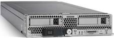
Figure 7 Cisco UCS B200 M4 Blade Server
Cisco UCS C220 M4 Rack Servers
The Cisco UCS C220 M4 Rack Server presents a 1RU rack-mount option to the Cisco UCS B200 M4. The Cisco UCS C220 M4 also leverages the power of the latest Intel® Xeon® E5-2600 v4 Series processor family CPUs with up to 1.5TB of RAM (using 64-GB DIMMs), four large form-factor (LFF) or eight small form-factor (SFF) solid-state drives (SSDs) or hard disk drives (HDDs), and up to 240Gbps throughput connectivity (with multiple VIC).
The Cisco UCS C220 M4 Rack Server can be standalone or UCS-managed by the fabric interconnect. It supports one mLOM connector for Cisco’s VIC 1387 or 1227 adapter and up to two PCIe adapters for Cisco’s VIC 1385, 1285, or 1225 models, which all provide Ethernet and FCoE.
![]() When using PCIe adapters in conjunction with mLOM adapters, single wire management will configure the mLOM adapter and ignore the PCIe adapter(s).
When using PCIe adapters in conjunction with mLOM adapters, single wire management will configure the mLOM adapter and ignore the PCIe adapter(s).
Figure 8 Cisco UCS C220 M4 Rack Server

For more information, see: http://www.cisco.com/c/en/us/support/servers-unified-computing/ucs-c220-m4-rack-server/model.html
Cisco I/O Adapters
The Cisco UCS blade server has various Converged Network Adapters (CNA) options. The Cisco UCS Virtual Interface Card (VIC) 1340 used in the solution is a two-port 40Gbps Ethernet or dual 4 x 10Gbps Ethernet, FCoE-capable modular LAN on motherboard (mLOM) designed exclusively for the M4 generation of Cisco UCS B-Series Blade Servers. When used in combination with an optional port expander, the Cisco UCS VIC 1340 capabilities is enabled for two ports of 40Gbps Ethernet.
The Cisco UCS VIC 1340 enables a policy-based, stateless, agile server infrastructure that can present over 256 PCIe standards-compliant interfaces to the host that can be dynamically configured as either network interface cards (NICs) or host bus adapters (HBAs). In addition, the Cisco UCS VIC 1340 supports Cisco® Virtual Machine Fabric Extender (VM-FEX) technology, which extends the Cisco UCS Fabric Interconnect ports to the virtual machines. This simplifies the server virtualization deployment and management.
Figure 9 Cisco UCS Virtual Interface Card (VIC) 1340

The personality of the card is determined dynamically at boot time using the service profile associated with the server. The number, type (NIC or HBA), identity (MAC address and World Wide Name [WWN]), failover policy, bandwidth, and quality-of-service (QoS) policies of the PCIe interfaces are all determined using the service profile. The capability to define, create, and use interfaces on demand provides a stateless and agile server infrastructure.
Each PCIe interface created on the VIC is associated with an interface on the Cisco UCS fabric interconnect, providing complete network separation for each virtual cable between a PCIe device on the VIC and the interface on the fabric interconnect.
For more information, see: http://www.cisco.com/c/en/us/products/interfaces-modules/ucs-virtual-interface-card-1340/index.html
Cisco UCS Differentiators
Cisco’s Unified Compute System is revolutionizing the way servers are managed in data-center. The following are the unique differentiators of Cisco UCS and Cisco UCS Manager.
1. Embedded Management —In Cisco UCS, the servers are managed by the embedded firmware in the Fabric Interconnects, eliminating need for any external physical or virtual devices to manage the servers.
2. Unified Fabric —In Cisco UCS, from blade server chassis or rack servers to FI, there is a single Ethernet cable used for LAN, SAN and management traffic. This converged I/O results in reduced cables, SFPs and adapters – reducing capital and operational expenses of overall solution.
3. Auto Discovery —By simply inserting the blade server in the chassis or connecting rack server to the fabric interconnect, discovery and inventory of compute resource occurs automatically without any management intervention. The combination of unified fabric and auto-discovery enables the wire-once architecture of UCS, where compute capability of UCS can be extended easily while keeping the existing external connectivity to LAN, SAN and management networks.
4. Policy Based Resource Classification —Once a compute resource is discovered by UCS Manager, it can be automatically classified to a given resource pool based on policies defined. This capability is useful in multi-tenant cloud computing. This CVD showcases the policy based resource classification of UCS Manager.
5. Combined Rack and Blade Server Management —Cisco UCS Manager can manage B-series blade servers and C-series rack server under the same UCS domain. This feature, along with stateless computing makes compute resources truly hardware form factor agnostic.
6. Model based Management Architecture —Cisco UCS Manager architecture and management database is model based and data driven. An open XML API is provided to operate on the management model. This enables easy and scalable integration of UCS Manager with other management systems.
7. Policies, Pools, Templates —The management approach in UCS Manager is based on defining policies, pools and templates, instead of cluttered configuration, which enables a simple, loosely coupled, data driven approach in managing compute, network and storage resources.
8. Loose Referential Integrity —In Cisco UCS Manager, a service profile, port profile or policies can refer to other policies or logical resources with loose referential integrity. A referred policy cannot exist at the time of authoring the referring policy or a referred policy can be deleted even though other policies are referring to it. This provides different subject matter experts to work independently from each-other. This provides great flexibility where different experts from different domains, such as network, storage, security, server and virtualization work together to accomplish a complex task.
9. Policy Resolution —In Cisco UCS Manager, a tree structure of organizational unit hierarchy can be created that mimics the real life tenants and/or organization relationships. Various policies, pools and templates can be defined at different levels of organization hierarchy. A policy referring to another policy by name is resolved in the organization hierarchy with closest policy match. If no policy with specific name is found in the hierarchy of the root organization, then special policy named “default” is searched. This policy resolution practice enables automation friendly management APIs and provides great flexibility to owners of different organizations.
10. Service Profiles and Stateless Computing —A service profile is a logical representation of a server, carrying its various identities and policies. This logical server can be assigned to any physical compute resource as far as it meets the resource requirements. Stateless computing enables procurement of a server within minutes, which used to take days in legacy server management systems.
11. Built-in Multi-Tenancy Support —The combination of policies, pools and templates, loose referential integrity, policy resolution in organization hierarchy and a service profiles based approach to compute resources makes UCS Manager inherently friendly to multi-tenant environment typically observed in private and public clouds.
12. Extended Memory — The enterprise-class Cisco UCS B200 M4 blade server extends the capabilities of Cisco’s Unified Computing System portfolio in a half-width blade form factor. The Cisco UCS B200 M4 harnesses the power of the latest Intel® Xeon® E5-2600 v3 Series processor family CPUs with up to 1536GB of RAM (using 64GB DIMMs) – allowing huge VM to physical server ratio required in many deployments, or allowing large memory operations required by certain architectures like big data.
13. Virtualization Aware Network —Cisco VM-FEX technology makes the access network layer aware about host virtualization. This prevents domain pollution of compute and network domains with virtualization when virtual network is managed by port-profiles defined by the network administrators’ team. VM-FEX also off-loads hypervisor CPU by performing switching in the hardware, thus allowing hypervisor CPU to do more virtualization related tasks. VM-FEX technology is well integrated with VMware vCenter, Linux KVM and Hyper-V SR-IOV to simplify cloud management.
14. Simplified QoS —Even though Fibre Channel and Ethernet are converged in UCS fabric, built-in support for QoS and lossless Ethernet makes it seamless. Network Quality of Service (QoS) is simplified in UCS Manager by representing all system classes in one GUI panel.
Cisco UCS new features specified in this design
The following new features of Cisco UCS unified software release have been incorporated into this design.
· vNIC Redundancy Pair —Supports two vNICs/vHBAs that are being configured with a common set of parameters through the vNIC/vHBA template pair. This prevents the configuration between two vNICs/vHBAs from going out of sync. Multiple vNIC/vHBA pairs can be created from the same vNIC/vHBA template pair. Only vNIC redundancy pairs were used in this validation since the vHBAs were each assigned a different VSAN.
· HTML 5 User Interface Improvements —Introduced the redesigned Cisco UCS Manager HTML 5 user interface to facilitate improved management of the Cisco UCS Manager ecosystem.
Cisco Nexus 9000 Series Switch
The Cisco Nexus 9000 Series Switches offer both modular and fixed 10/25/40/50/100 Gigabit Ethernet switch configurations with scalability up to 60Tbps of non-blocking performance with less than five-microsecond latency, non-blocking Layer 2 and Layer 3 Ethernet ports and wire speed VxLAN gateway, bridging, and routing support.
The VersaStack design covered in this document uses NX-OS mode of operation using a pair of Cisco Nexus 9300 Series (Cisco Nexus 9372PX) switches.
For more information, refer to:
http://www.cisco.com/c/en/us/products/switches/nexus-9000-series-switches/index.html
Cisco Nexus 1000v (Optional)
The Cisco Nexus 1000v is a distributed virtual switch that extends the network edge into the virtual environment of multiple differing hypervisors with an NX-OS CLI implementation. It provides QoS, ERSPAN, VxLAN support and many other features that may not be present in a standard or distributed virtual switch that is native to a hypervisor.
For more information, refer to:
· http://www.cisco.com/en/US/products/ps9902/index.html
· http://www.cisco.com/en/US/products/ps10785/index.html
IBM Storwize V5000 2nd Generation
IBM Storwize V5000 is designed for software-defined environments and is built with IBM Spectrum Virtualize software. The IBM Storwize family is an industry-leading solution for storage virtualization that includes technologies to complement and enhance virtual environments, delivering a simpler, more scalable, and cost-efficient IT infrastructure.
Storwize V5000 is a highly flexible, easy to use, virtualized hybrid storage system designed to enable midsized organizations to overcome their storage challenges with advanced functionality. Storwize V5000 second-generation models offer improved performance and efficiency, enhanced security, and increased scalability with a set of three models to deliver a range of performance, scalability, and functional capabilities.
Storwize V5000 second-generation offer three hybrid models – IBM Storwize V5030, IBM Storwize V5020 and IBM Storwize V5010 – providing the flexibility to start small and keep growing while leveraging existing storage investments. Plus, to enable organizations with midsized workloads to achieve advanced performance, IBM Storwize V5030F provides a popularly priced all-flash solution. IBM Spectrum Virtualize
Figure 10 IBM Storwize V5030

The storage model leveraged for this design is the IBM Storwize V5030. IBM Storwize V5030 control enclosure models offer the highest levels of performance, scalability, and functionality with:
· Two 6-core processors and up to 64GB of cache
· Support for 504 drives per system with the attachment of 20 Storwize V5000 expansion enclosures and 1,008 drives with a two-way clustered configuration
· External virtualization to consolidate and provide Storwize V5000 capabilities to existing storage infrastructures
· Real-time Compression for improved storage efficiency
· Encryption of data at rest stored within the Storwize V5000 system and externally virtualized storage systems
All Storwize V5000 second-generation control enclosures include:
· Dual-active, intelligent node canisters with mirrored cache
· Ethernet ports for iSCSI connectivity
· Support for 16Gb FC, 12Gb SAS, 10Gb iSCSI/FCoE, and 1Gb iSCSI for additional I/O connectivity
· Twelve 3.5-inch (LFF) drive slots or twenty four 2.5-inch (SFF) drive slots within the 2U, 19-inch rack mount enclosure
· Support for the attachment of second-generation Storwize V5000 LFF and SFF 12Gb SAS expansion enclosures
· Support for a rich set of IBM Spectrum Virtualize functions including thin provisioning, IBM EasyTier, FlashCopy, and remote mirroring
· Either 100-240V AC or -48V DC power supplies
· Either a one- or three-year warranty with customer replaceable units (CRU) and on-site service
All Storwize V5000 functional capabilities are provided through IBM Spectrum Virtualize Software for Storwize V5000. For additional information about Storwize V5000 functional capabilities and software, refer to the IBM Storwize V5000 website: http://www.ibm.com/systems/uk/storage/disk/storwize_v5000/
IBM Spectrum Virtualize
IBM® Spectrum Virtualize™ provides an ideal way to manage and protect the huge volumes of data organizations use for big data analytics and new cognitive workloads. IBM Spectrum Virtualize is a proven offering that is available for years in IBM SAN Volume Controller (SVC). IBM Storwize® family of storage solutions, IBM FlashSystem® V9000 and IBM VersaStack™—with more than 130,000 systems are running IBM Spectrum Virtualize. These systems are delivering better than five nines of availability while managing more than 5.6 exabytes of data.
IBM Spectrum Virtualize Software V7.7.1.x includes the following key improvements:
· Reliability, availability, and serviceability with NPIV host port fabric virtualization, Distributed RAID support for encryption, and IP Quorum in GUI
· Scalability with support for up to 10,000 volumes (virtual disks), depending on the model; and up to 20 Expansion Enclosures on SVC DH8 and SV1 models and on FlashSystems V9000
· Manageability with CLI support for host groups
· Virtualization of iSCSI-attached external storage arrays including XIV(R) Gen 3, Spectrum Accelerate, FlashSystems A9000 and FlashSystems A9000R arrays.
· Performance with 64 GB read cache
· Data economics with Comprestimator in the GUI
· Licensing of compression formally added to the External Virtualization software package of Storwize V5030
· Software licensing metrics to better align the value of SVC software with Storage use cases through Differential Licensing
Key existing functions of IBM Spectrum Virtualize include:
· Virtualization of Fibre Channel-attached external storage arrays with support for almost 370 different brands and models of block storage arrays , including arrays from competitors
· Manage virtualized storage as a single storage pool, integrating "islands of storage" and easing the management and optimization of the overall pool
· Real-time Compression™ for in-line, real-time compression to improve capacity utilization
· Virtual Disk Mirroring for two redundant copies of LUN and higher data availability
· Stretched Cluster and HyperSwap® for high availability among physically separated data centers
· Easy Tier® for automatic and dynamic data tiering
· Distributed RAID for better availability and faster rebuild times
· Encryption to help improve security of internal and externally virtualized capacities
· FlashCopy® snapshots for local data protection
· Remote Mirror for synchronous or asynchronous remote data replication and disaster recovery through both Fibre Channel and IP ports with offerings that utilize IBM Spectrum Virtualize software
· Clustering for performance and capacity scalability
· Online, transparent data migration to move data among virtualized storage systems without disruptions
· Common look and feel with other offerings that utilize IBM Spectrum Virtualize software
· IP Link compression to improve usage of IP networks for remote-copy data transmission.
More information can be found on the IBM Spectrum Virtualize website.
http://www-03.ibm.com/systems/storage/spectrum/virtualize/index.html
VMware vSphere
VMware vSphere is a virtualization platform for holistically managing large collections of infrastructure (resources-CPUs, storage and networking) as a seamless, versatile, and dynamic operating environment. Unlike traditional operating systems that manage an individual machine, VMware vSphere aggregates the infrastructure of an entire data center to create a single powerhouse with resources that can be allocated quickly and dynamically to any application in need.
Among the changes new in vSphere 6.0 U2 used in this design, there is a new HTML 5 installer supporting options for install and upgrade of vCenter Server. Also included is a new Appliance Management user interface and a UI option for the Platform Services Controller. Additionally, an ESXi host web-based configuration utility is used for initial setup of VMware ESXi.
For more information, refer to: http://www.vmware.com/products/datacenter-virtualization/vsphere/overview.html
Domain and Element Management
This section of the document provides general descriptions of the domain and element managers relevant to the VersaStack:
· Cisco UCS Manager
· Cisco UCS Central
· IBM Spectrum Virtualize management GUI for IBM Storwize V5030
· VMware vCenter™ Server
Cisco Unified Computing System Manager
Cisco UCS Manager provides unified, centralized, embedded management of all Cisco Unified Computing System software and hardware components across multiple chassis and thousands of virtual machines. Administrators use the software to manage the entire Cisco Unified Computing System as a single logical entity through an intuitive GUI, a command-line interface (CLI), or an XML API.
The Cisco UCS Manager resides on a pair of Cisco UCS 6300 or 6200 Series Fabric Interconnects using a clustered, active-standby configuration for high availability. The software gives administrators a single interface for performing server provisioning, device discovery, inventory, configuration, diagnostics, monitoring, fault detection, auditing, and statistics collection. Cisco UCS Manager service profiles and templates support versatile role- and policy-based management, and system configuration information can be exported to configuration management databases (CMDBs) to facilitate processes based on IT Infrastructure Library (ITIL) concepts. Service profiles benefit both virtualized and non-virtualized environments and increase the mobility of non-virtualized servers, such as when moving workloads from server to server or taking a server offline for service or upgrade. Profiles can be used in conjunction with virtualization clusters to bring new resources online easily, complementing existing virtual machine mobility.
For more information on Cisco UCS Manager, click the following link:
http://www.cisco.com/en/US/products/ps10281/index.html
Cisco UCS Central (Optional)
Cisco UCS Central is an optional component in the VersaStack design which provides Cisco UCS customers managing growth within a single data center, growth across multiple sites, or both, Cisco UCS Central Software centrally manages multiple Cisco UCS domains using the same concepts that Cisco UCS Manager uses to support a single UCS domain. Cisco UCS Central Software manages global resources (including identifiers and policies) that can be consumed within individual Cisco UCS Manager instances. It can delegate the application of policies (embodied in global service profiles) to individual UCS domains, where Cisco UCS Manager puts the policies into effect. Cisco UCS Central software manages multiple, globally distributed Cisco UCS domains from a single pane. Every instance of Cisco UCS Manager and all of the components managed by it form a domain. Cisco UCS Central integrates with Cisco UCS Manager, and utilizes it to provide global configuration capabilities for pools, policies, and firmware.
UCS Manager (Mini) Management with UCS Central
Cisco UCS Central Software is designed and operates comparable to Cisco UCS Manager in that policies and configuration definitions, which make up a Cisco UCS service profile, can be created at a central location and then applied to the endpoint recipient, where they are resolved. With Cisco UCS Manager, the endpoint recipients are the Cisco UCS infrastructure (servers, network, etc.).
For Cisco UCS Central Software, the recipients are individual Cisco UCS Manager instances that have been registered with Cisco UCS Central Software. With Cisco UCS Central Software, global Cisco UCS service profiles are defined centrally and are passed to Cisco UCS Manager instances according to the way they are registered with Cisco UCS Central Software (Figure 11).
Figure 11 Cisco UCS Manager (Mini) Management with UCS Central

IBM Spectrum Virtualize Easy-to-Use Management GUI
IBM Spectrum Virtualize™ includes an easy-to-use management GUI to help you to monitor, manage, and configure your system (Figure 12). With this single interface, administrators can perform configuration, management and service tasks in a consistent manner over multiple storage systems—even from different vendors—vastly simplifying management and helping reduce the risk of errors.
IT staff can also use built-in monitoring capabilities (Figure 13) to securely check the health and performance of the system remotely from the GUI or from a mobile device.
In addition, plug-ins to support VMware vCenter help enable more efficient, consolidated management in these environments.
Figure 12 IBM Spectrum Virtualize Management GUI Example

Figure 13 Real-time Performance Monitoring on the IBM Spectrum Virtualize Management GUI

VMware vCenter Server
VMware vCenter is a virtualization management application for managing large collections of IT infrastructure resources such as processing, storage and networking in a seamless, versatile and dynamic manner. It is the simplest and most efficient way to manage VMware vSphere hosts at scale. It provides unified management of all hosts and virtual machines from a single console and aggregates performance monitoring of clusters, hosts, and virtual machines. VMware vCenter Server gives administrators a deep insight into the status and configuration of compute clusters, hosts, virtual machines, storage, the guest OS, and other critical components of a virtual infrastructure. A single administrator can manage 100 or more virtualization environment workloads using VMware vCenter Server, more than doubling the typical productivity in managing physical infrastructure. VMware vCenter manages the rich set of features available in a VMware vSphere environment.
For more information, refer to: http://www.vmware.com/products/vcenter-server/overview.html
Cisco Virtual Switch Update Manager (Optional)
Cisco Virtual Switch Update Manager (Cisco VSUM) is required when Nexus 1000v distributed virtual switch is used in the solution. Cisco VSUM enables you to install, upgrade, and monitor the Cisco Nexus 1000V for VMware vSphere and also migrate hosts to the Cisco Nexus 1000V, using the VMware vSphere Web Client.
Cisco VSUM enables you to do the following:
· Install the Cisco Nexus 1000V switch.
· Migrate the VMware vSwitch and VMware vSphere Distributed Switch (VDS) to the Cisco Nexus 1000V.
· Monitor the Cisco Nexus 1000V.
· Upgrade the Cisco Nexus 1000V and added hosts from an earlier version to the latest version.
· Install the Cisco Nexus 1000V license.
· View the health of the virtual machines in your data center using the Dashboard - Cisco Nexus 1000V.
For more information on Cisco VSUM, click the following link:
VersaStack Design Principles
VersaStack addresses four primary design principles: availability, scalability, flexibility, and manageability. These architecture goals are as follows:
· Availability: Makes sure that services are accessible and ready to use for the applications.
· Scalability: Addresses increasing demands with appropriate resources.
· Flexibility: Provides new services or recovers resources without requiring infrastructure modification.
· Manageability: Facilitates efficient infrastructure operations through open standards and APIs.
![]() Performance is a key design criterion that is not directly addressed in this document. It has been addressed in other collateral, benchmarking, and solution testing efforts; this design guide validates the functionality.
Performance is a key design criterion that is not directly addressed in this document. It has been addressed in other collateral, benchmarking, and solution testing efforts; this design guide validates the functionality.
This section of the document will address the physical and logical topology of the VersaStack design.
This VersaStack design uses the compact version of Cisco UCS (Cisco UCS Mini) with Cisco B200 M4 half-width blades and Cisco UCS C220 M4 rack mount servers managed through Cisco UCS manager. These high performance servers are configured as stateless compute nodes where ESXi 6.0 U2 hypervisor is loaded using SAN (iSCSI and FC) boot. The boot disks to store ESXi hypervisor installations and configuration along with the block based VMware Datastores to host application data and virtual machines (VMs) are provisioned on the IBM V5030 storage array.
As discussed earlier, the VersaStack Models with Cisco UCS Mini are characterized by the IBM Storwize V5030 storage connectivity options within the architecture. Currently, these models include:
· Direct Attached SAN Storage
· IP-Based Storage
Direct Attached Design with Fibre Channel based SAN Storage
VersaStack can be deployed in a Direct Attached configuration to eliminate the requirement for separate Fibre Channel switches. In this type of deployment, the flexibility of the fabric interconnects is leveraged and they are changed to FC Switching Mode. With the introduction of firmware version 2.1(1a), Cisco has introduced UCSM based FC zoning for direct connected topologies. This eliminates the need to have an upstream switch host the FC zoning database as the zoning can be handled within the Fabric Interconnects. The FC zoning is automated through Cisco UCS SAN Connectivity Polies and applied on the Cisco UCS Fabric Interconnects to simplify deployment of new servers.
There are two SAN fabrics created; one each on the Cisco UCS Fabric Interconnects. The IBM Storwize V5030 storage controller node canisters have four 16Gbps Fibre Channel ports, two ports on each node canister are used and are connected to Fabric-A and Fabric-B respectively. Each ESXi host from the Cisco UCS mini is also connected to both the fabrics, this provides high availability in case of a SAN fabric fault or node failure.
Figure 14 below details cabling connectivity of VersaStack Direct Attached Storage topology in the compute, network, and storage layers.
Figure 14 VersaStack Direct Attached SAN Storage Logical Topology

IP-Based Design using iSCSI Storage
This design is an IP-Based storage solution with iSCSI block storage access. The storage design uses an IBM Storwize V5030 storage controller to provide block storage using iSCSI. The two-node canister IBM Storwize V5030 storage controller can be redundantly connected to the Nexus fabric using four 10Gbps Ethernet ports on the host interface cards with optical SFPs, with each node canister having connectivity to both the switches. Each of these ports are used for iSCSI data transfers. The design uses two distinct IP domains with distinct iSCSI targets and uses host multipathing to provide storage high availability.
The design is highly available with no single point of failure between the compute, network and storage subsystems. The Cisco UCS Mini, Cisco Nexus 9000 switches and Storwize V5030 storage controller are redundantly connected using the cabling configuration is shown in Figure 15. The Cisco Unified Computing System and Cisco Nexus 9000 platforms support active port channeling using 802.3ad standard Link Aggregation Control Protocol (LACP). Port channeling is a link aggregation technique offering link fault tolerance and traffic distribution (load balancing) for improved aggregate bandwidth across member ports. Virtual PortChannels are not used in the connectivity between the IBM Storwize V5030 and Cisco Nexus 9000 switches.
Figure 15 below details fully redundant VersaStack IP-Based Storage logical topology in the compute, network, and storage layers.
Figure 15 VersaStack IP-Based Storage logical Topology

![]() The VersaStack IP-Based Design covered in this document highlights an alternative, supported, design option. The IP-Based design in not validated as part of the VersaStack with Cisco UCS Mini and IBM V5000 2nd Generation Design Guide CVD. For a validated IP-Based Deployment Guide, please refer to the V5000 1st Generation storage Deployment Guide at: www.cisco.com/c/en/us/td/docs/unified_computing/ucs/UCS_CVDs/Versastack_n5k_mini.html
The VersaStack IP-Based Design covered in this document highlights an alternative, supported, design option. The IP-Based design in not validated as part of the VersaStack with Cisco UCS Mini and IBM V5000 2nd Generation Design Guide CVD. For a validated IP-Based Deployment Guide, please refer to the V5000 1st Generation storage Deployment Guide at: www.cisco.com/c/en/us/td/docs/unified_computing/ucs/UCS_CVDs/Versastack_n5k_mini.html
Network Design
The Network fabric with in the solution consists of two Cisco Nexus 9372PX switches deployment for high availability and provides 10G enabled, 40G capable network fabric. Link aggregation using virtual PortChannels (vPC) is used in this design to provide higher aggregate bandwidth and fault tolerance between the Cisco Nexus switches and the Cisco UCS Mini.
Virtual PortChannels allow links that are physically connected to two different Cisco Nexus 9000 Series devices to appear as a single logical link to a third device - Cisco UCS Mini in this case. In a switching environment, vPC provides the following benefits:
· Allows a single device to use a portchannel across two upstream devices
· Eliminates Spanning Tree Protocol blocked ports and uses all available uplink bandwidth, thereby increasing the aggregate bandwidth into the UCS domain.
· Provides a loop-free topology
· Provides fast convergence if either one of the physical links or a device fails
· Helps ensure high availability of the overall VersaStack system
VersaStack with UCS Mini Network Connectivity
Cisco UCS Fabric Interconnects are configured with two portchannels, one from each FI, to the Cisco Nexus 9372 switches. These portchannels carry all the data and IP-based storage traffic originated on the Cisco Unified Computing System. Virtual PortChannels (vPC) are configured on the Cisco Nexus 9372 to provide device level redundancy. The validated design utilized two uplinks from each fabric interconnects to the Cisco Nexus switches for an aggregate bandwidth of 20GbE (2 x 10GbE).
Figure 16 VersaStack with UCS Mini Network Connectivity

![]() Figure 16 above shows the IBM Storwize V5030 10GbE redundant network connectivity to the Nexus 9372 switches. This connectivity is used in the IP-Based storage design for iSCSI storage access only and is not required for Direct Attached storage access enabled through Fibre Channel.
Figure 16 above shows the IBM Storwize V5030 10GbE redundant network connectivity to the Nexus 9372 switches. This connectivity is used in the IP-Based storage design for iSCSI storage access only and is not required for Direct Attached storage access enabled through Fibre Channel.
Cisco Nexus 9000-Series Switches vPC Best Practices
Cisco Nexus 9000-Series switches related best practices used in the validation of the VersaStack architecture are summarized below:
· Cisco Nexus 9000 features enabled
— Link Aggregation Control Protocol (LACP part of 802.3ad)
— Cisco Virtual Port Channeling (vPC) for link and device resiliency
— Cisco Discovery Protocol (CDP) for infrastructure visibility and troubleshooting
— Link Layer Discovery Protocol (LLDP) for infrastructure visibility and troubleshooting
· vPC considerations
— Define a unique domain ID
— Set the priority for the intended vPC primary switch lower than the secondary (default priority is 32768)
— Establish peer keepalive connectivity. It is recommended to use the out-of-band management network (mgmt0) or a dedicated switched virtual interface (SVI)
— Enable vPC auto-recovery feature
— Enable peer-gateway. Peer-gateway allows a vPC switch to act as the active gateway for packets that are addressed to the router MAC address of the vPC peer allowing vPC peers to forward traffic
— Enable IP ARP synchronization to optimize convergence across the vPC peer link.
![]() Cisco Fabric Services over Ethernet (CFSoE) is responsible for the synchronization of configurations, spanning tree, MAC and VLAN information, which removes the requirement for explicit configuration. This service is enabled by default.
Cisco Fabric Services over Ethernet (CFSoE) is responsible for the synchronization of configurations, spanning tree, MAC and VLAN information, which removes the requirement for explicit configuration. This service is enabled by default.
— A minimum of two 10 Gigabit Ethernet connections are required for vPC
— All port channels should be configured in LACP active mode
· Spanning tree considerations
— The spanning tree priority was not modified. Peer-switch (part of vPC configuration) is enabled which allows both switches to act as root for the VLANs
— Loop guard is disabled by default
— BPDU guard and filtering are enabled by default
— Bridge assurance is only enabled on the vPC peer link
For configuration details, refer to the Cisco Nexus 9000-Series switches configuration guides:
Storage Design
IBM Storwize V5000 2nd Generation
The IBM Storwize V5000 offers block storage connectivity with onboard 12Gb SAS expansion connectors and 1Gb or 10Gb Ethernet. Further connectivity is catered for with optional 16Gb FC, 12Gb SAS or 10Gb FCoE/iSCSI. In this Validated Design, we have chosen to leverage the 10Gb iSCSI and 16Gb FC ports for host connectivity.
The base model of IBM Storwize V5030 leveraged in this design has a pair of node canisters which are referred to, collectively, as an I/O group. The IBM Storwize V5030 can support 2 storage controllers in a clustered system, which provides two I/O groups, allowing for further redundancy and scalability.
When a host server performs I/O to one of its volumes, all the I/O for that volume is directed to the I/O group where the volume has been defined. Under normal conditions, the same node within that I/O GROUP also always processes these I/Os.
Both nodes of the I/O group act as preferred nodes for their own specific subset of the total number of volumes that the I/O group presents to the host servers via the Cisco UCS Fabric Interconnects. However, both nodes also act as a failover node for the partner node within the I/O group. Therefore, a node takes over the I/O workload from its partner node (if required) without affecting the server’s application.
The active/active architecture provides availability to process I/O for both controller nodes and allows the application to continue running smoothly, even if the server has only one access route or path to the storage controller. This type of architecture eliminates the path/LUN thrashing that is typical of an active/ passive architecture.
ESXi hosts in the Cisco UCS Mini use iSCSI LUNs in the IP-Based storage design and FC LUNs in the Direct Attached SAN storage design to SAN boot and do not require local disks. A volume in the Storwize V5030 I/O group appears as a single device to the applications on hosts, even though the multipathing driver can detect four separate devices for each volume. The multipathing driver selects one or more of these devices during I/O. If the connection between the host and one Storwize V5030 node port is lost, the multipathing driver can select an alternative path to the Storwize V5030 I/O group. The I/O between the host and IBM Storwize V5030 continue without error.
IBM Storwize V5030 Direct Attached SAN connectivity to Cisco UCS Mini
VersaStack with UCS Mini uses IBM Storwize V5030 array for block storage access. The VersaStack design leverages direct attach storage option for Fibre Channel access to IBM Storwize V5030 storage array. The UCS fabric interconnect provides 4/8Gbps FC switching capability both for SAN boot of the UCS servers and for mapping of FC application data disks. FC storage connects to the fabric interconnect at 8Gb/s.
Figure 17 IBM Storwize V5030 Direct Attached SAN Connectivity

IBM Storwize V5030 Network Connectivity for iSCSI Storage access
To support iSCSI based IP-only storage connectivity, each IBM V5030 node is connected to each of the Cisco Nexus 9372 switch. The physical connectivity is shown in Figure 18. In this design, each 10Gbps Ethernet port between the storage node and the Nexus fabric is configured for either iSCSI-A or iSCSI-B path.
Figure 18 IBM Storwize V5030 iSCSI Connectivity

Compute Design
The VersaStack compute design supports both Cisco UCS B-Series and C-Series deployments. The Cisco UCS supports the virtual server environment by providing robust, highly available, and extremely manageable compute resources. In this validation effort, multiple Cisco UCS B-Series and C-Series ESXi servers are booted from SAN using iSCSI or FC (depending on the storage design option).
As stated earlier, Cisco UCS Mini has built-in redundant fabric interconnects (FI) providing unified network and storage access. Each fabric interconnect has 4x10Gbps ports and a 40Gbps scalability port. Two 10Gbps ports will be used as Uplink ports and connect to the switching infrastructure supporting applications, user and storage traffic in the IP-Based storage design as illustrated in Figure 16 above. The remaining ports can be configured as Appliance ports for direct storage connectivity with Direct Attached storage option as illustrated in Figure 17. The number of rack servers supported will be effected if storage is directly attached to the fabric interconnects.
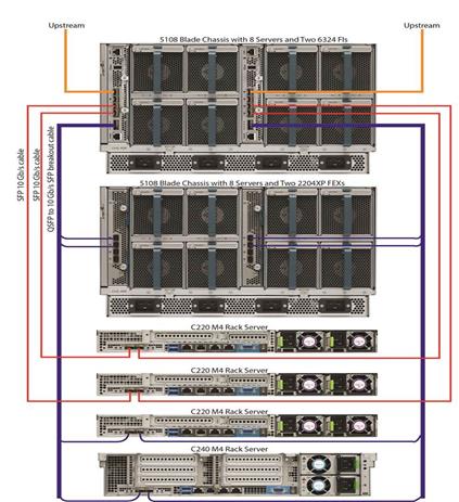
The 40Gbps (Scalability Port) can be used with a breakout cable that transforms the port to 4 x 10Gbps cables. These cables are connected to 2nd Cisco UCS Chassis with in the architecture; however they can also be used for UCS C-Series servers or storage connections. The scalability port in this design was used to extend the UCS domain with addition of 2nd UCS Chassis and for UCS C-series connectivity.
Figure 19 UCS 6324 Fabric Interconnect Ports

Compute Virtualization Design
VMware vCenter is used to deploy VMware HA clusters to allow VMs to failover in the event of a server failure. VMware vMotion and VMware HA are enabled to auto restart VMs after a failure. Host monitoring is enabled to monitor heartbeats of all ESXi hosts in the cluster for faster detection. Admission Control is also enabled on the blade servers to ensure the cluster has enough resources to accommodate a single host failure.
Each UCS Server running ESXi 6.0 U2 was deployed using Cisco UCS 1340 VIC network adapter. At the server level, each Cisco VIC presents multiple virtual PCIe devices (vNICs and vHBAs) to ESXi node. The vSphere environment identifies these interfaces as vmnics and vmhbas, the ESXi operating system is unaware these are virtual adapters. The result is a dual-homed ESXi node to the network and SAN. All of the server NICs and HBAs are configured to use both the Cisco UCS Fabric Interconnects to avoid traffic disruptions.
Figure 20 below shows the ESXi host vNIC and vmk distribution with iSCSI based Storage Access. Two dedicated vNICs and vSwitches are used within the ESXi servers for iSCSI storage access for redundancy as shown below.
Note that when the VMware vDS is used, In-band management and the VMkernel interfaces are left on the vSwitch (normally vSwitch0). This is done to ensure that the ESXi host can reboot and communicate with VMware vCenter properly because the VMware vDS on the ESXi host must retrieve its configuration from vCenter to begin forwarding packets. vMotion is also left on a dedicated vSwitch when the VMware vDS is used.
When the optional Cisco Nexus 1000V is used, both vSwitch0 and the vDS vNICs are migrated to the Nexus 1000V. Two uplink port profiles are created for these vNICs and system VLANs are utilized for In-band management and any iSCSI VMkernel port profiles.
Figure 20 ESXi Host vNIC and vmk Distribution with iSCSI based Storage Access

Figure 21 below shows similar configuration for an FC connected ESXi host. In this case, the Fibre Channel SAN-A and SAN-B traffic is handled by two dedicated vHBAs. The resulting ESXi host configuration therefore has a combination of vSwitch and vDS/Nexus 1000v to support network traffic and vHBAs for FC storage access.
Figure 21 ESXi Host vNIC, vHBA and vmk Distribution with FC Storage Access

VMware vSphere hosts use SAN multipathing to access LUNs on the IBM storage devices. If any component (NIC, HBA, FI, IBM controller, cables) along a path fails, all storage traffic will re-route to an alternate path. The multipathing driver can select an alternative path to the Storwize V5030 I/O group. The I/O between the host and Storwize V5030 continue without error. When both paths are active, traffic is load balanced.
In the Direct Attached Storage design, each UCS blade used a single Service Profile with two vHBAs having connectivity to SAN fabric-A and SAN Fabric-B as shown in the Figure 22. Each vHBA is zoned to a different set of Storwize V5030 system ports to maximize performance and redundancy. The ESX host was deployed in a cluster similar to iSCSI design providing HA failover without single point of failure at hypervisor layer and MPIO host software was utilized for path management.
Figure 22 ESXi Host Fibre Channel SAN storage access

Figure 23 shows the ESXi host access to iSCSI Storage LUNs on the IBM Storage V5030 with dedicated iSCSI vNICs providing high availability.
Figure 23 ESXi Host IP-Based iSCSI Storage access

Cisco UCS C-series Server Connectivity
In all VersaStack designs, Cisco UCS C-series rack mount servers are always connected via the UCS FIs and managed through UCS Manager to provide a common management look and feel. Cisco UCS Manager 2.2 and later versions allow customers to connect Cisco UCS C-Series servers directly to Cisco UCS Fabric Interconnects without requiring a Fabric Extender (FEX). In the VersaStack design, two UCS C220-M4 servers were directly attached to UCS FI on Scalability port using two 10Gbps converged connections (one connection to each FI). The UCS C-Series servers can also be connected on the 10Gbe ports on the Cisco UCS 6324 Fabric Interconnects if available.
Cisco Unified Computing System –Jumbo Frames
Enabling jumbo frames in a VersaStack environment optimizes throughput between devices by enabling larger size frames on the wire while reducing the CPU resources to process these frames. VersaStack supports wide variety of traffic types (vMotion, iSCSI, control traffic, etc.) that can benefit from a larger frame size. Cisco UCS policies enable and deliver the jumbo frame functionality. In VMware vSphere, the jumbo frames are configured by setting MTU sizes at both vSwitches and VMkernel ports. On IBM storage systems, the MTU size on the interfaces is modified to enable jumbo frame. In this validation effort, VersaStack was configured to support jumbo frames with an MTU size of 9000.
![]() When setting the Jumbo frames, it is important to make sure MTU settings are applied uniformly across the stack at all interfaces in the network to prevent packet drops and negative performance. Also, Jumbo frames should only be used on isolated VLANs within the pod, such as vMotion and any storage VLANs. VLANs with the external connectivity should use the default frame size, 1500 MTU. Make sure they are not set to Jumbo frame.
When setting the Jumbo frames, it is important to make sure MTU settings are applied uniformly across the stack at all interfaces in the network to prevent packet drops and negative performance. Also, Jumbo frames should only be used on isolated VLANs within the pod, such as vMotion and any storage VLANs. VLANs with the external connectivity should use the default frame size, 1500 MTU. Make sure they are not set to Jumbo frame.
Management Network
A separate out-of-band management network was used for configuring and managing compute, storage and network infrastructure components in the solution. Management ports on each IBM Storwize V5030 and Cisco UCS Mini FIs were physically connected to a separate dedicated management switch. Management ports on Cisco Nexus 9372PXs were also connected into the same management switch.
Access to VMware vCenter and ESXi hosts were done through in-band. Out-of-band access to these components can be enabled, but would require additional ports on the Cisco UCS 6324 Fabric Interconnects. A disjoint layer-2 configuration can then be used to keep the management and data plane networks completely separate. This would require two additional vNICs (for example, OOB-Mgmt-A, OOB-Mgmt-B) on each of the servers, after which they can be associated with the management uplink ports.
Compute and Storage Scalability
Compute Scalability
The VersaStack design with Cisco UCS Mini and IP-based storage can support a maximum of 20 half-width blade servers within two Cisco UCS 5108 chassis. With the IP-based storage connectivity model there are two 10Gbps SFP+ ports available to support two rack-mount UCS C-Series servers. Additionally, the Cisco UCS Mini can support a second Cisco UCS Chassis with eight blades and up to two Cisco UCS rack-mount servers using the 40GbE Enhanced Quad SFP (QSFP+) ports on the Cisco UCS 6324 Fabric Interconnects.
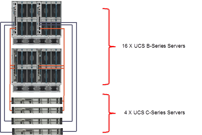
The Figure 24 below shows the maximum compute scale possible in a VersaStack design with Direct Attached SAN storage. Assuming that two ports on each Cisco UCS 6324 Fabric Interconnect are used for Ethernet traffic and two more ports used for SAN storage connectivity, the maximum compute scale possible with this design is a eighteen; sixteen half-width Cisco UCS B-Series blade servers and two Cisco UCS C-Series rack-mount servers.
Figure 24 Compute scalability with Direct Attached SAN Storage

The Figure 25 below shows the maximum compute scale possible in a VersaStack design with IP-based storage. Assuming that two ports on each Cisco UCS 6324 Fabric Interconnect are used for Ethernet traffic, the maximum compute scale possible with this design is a twenty; sixteen half-width Cisco UCS B-Series blade servers and four Cisco UCS C-Series rack-mount servers.
Figure 25 Compute scalability with IP-Based Storage
Storage Scalability
The VersaStack design provides flexible storage scaling with the Storwize V5030 storage controller. The Storwize V5030 storage controller provides 12Gb SAS internal dual-port drive connectivity, and each control enclosure also has four 12Gb SAS x 4 (Mini-SAS HD SFF-8644) ports (2 ports per node canister) for 12Gb SAS expansion enclosure connectivity.
The Storwize V5030 storage controller supports the attachment of up to 20 Large From Factor (LFF), 20 Small Form Factor (SFF) or 8 High Density (HD) expansion enclosures with a maximum of 760 drives per storage controller, providing more than 11 petabytes (PB) of storage per system. Intermix of LFF and SFF enclosures are supported. The expansion enclosures can be added to the system non-disruptively.
Each Storwize V5000 Second Generation expansion unit ships with two expansion canisters. Each expansion canister provides 12Gb SAS connectivity to the internal drives and two external 12Gb SAS x 4 ports (MiniSAS HD SFF-8644 connectors labeled Port 1 and Port 2) that are used to connect the IBM Storwize V5030 node canisters and also for connecting the expansion enclosures between each other. One of the expansion ports (port 1 or port 2) on the left and right node canisters is connected to the port 1 on the left and right expansion canisters, respectively. The port 2 on the left and right expansion canisters is connected to the port 1 on the left and right expansion canisters in the adjacent enclosure, respectively, and so on.
Figure 26 IBM Storwize V5030 Scalability

Up to 10 SFF and LFF expansion enclosures and 4 HD expansion enclosures can be connected to Port 1 in a daisy-chained manner, and up to 10 SFF and LFF expansion enclosures and 4 HD expansion enclosures can be connected to Port 2 in a daisy-chained manner, for a total of 20 LFF/SFF expansion enclosures and 8 HD expansion enclosures per one control enclosure.
A high level summary of the VersaStack validation is provided in this section. The solution was validated for basic data forwarding by deploying virtual machines running IOMeter tool. The system was validated for resiliency by failing various aspects of the system under load. Examples of the types of tests executed include:
· Failure and recovery of ESXi hosts in a cluster
· Rebooting of SAN boot hosts
· Service Profile migration between blades
· Failure of Nexus switches one at a time
· Failure and recovery of redundant links to IBM Storwize V5030 nodes
· Failure and recovery of SSD and spinning disks
· Storage link failure between one of the Storwize V5030 nodes and the fabric interconnect
· Load was generated using IOMeter tool and different IO profiles were used to reflect the different profiles that are seen in customer networks
Hardware and Software Revisions
Table 2 describes the hardware and software versions used during solution validation. It is important to note that Cisco, IBM, and VMware have interoperability matrices that should be referenced to determine support for any specific implementation of VersaStack. Please refer to the following links for more information:
· IBM System Storage Interoperation Center
· Cisco UCS Hardware and Software Interoperability Tool
Table 2 VersaStack Hardware and Software revisions
| Layer |
Device |
Version or Release |
Details |
| Compute |
Cisco UCS fabric interconnect |
3.1(2c) |
Embedded management |
| Cisco UCS C 220 M3/M4, Cisco UCS B 200 M3/ M4 |
3.1(2c) |
Software bundle release |
|
| Cisco eNIC |
2.3.0.10 |
Ethernet driver for Cisco VIC |
|
| Cisco fNIC |
1.6.0.28 |
FCoE driver for Cisco VIC |
|
| Network |
Cisco Nexus 9372PX |
7.0(3) I2(4) |
Operating system version |
|
|
|
|
|
| Storage |
IBM Storwize V5030 |
7.7.1.3 |
Software version |
| LFF Expansion (2078-312) |
|||
| Software |
Cisco UCS hosts |
VMware vSphere ESXi™ 6.0u2 |
Operating system version |
| VMware vCenter™ |
6.0u2 |
VM (1 each): VMware vCenter |
|
| Cisco Nexus 1000v (optional) |
5.2(1)SV3(2.1) |
Software version |
|
|
|
Virtual Switch Update Manager (VSUM) (only if you install Cisco Nexus 1000v) |
2.0 |
Virtual Switch Deployment Software |
While VersaStack Deployment CVDs are configured with specific hardware and software, the components used to deploy a VersaStack can be customized to suit the specific needs of the environment as long as all the components and operating systems are on the HCL lists referenced in this document.
VersaStack solution combines the innovation of Cisco UCS Integrated Infrastructure with the efficiency of the IBM storage systems. The Cisco UCS Integrated Infrastructure includes the Cisco Unified Computing System (Cisco UCS), Cisco Nexus, Cisco MDS switches, and Cisco UCS Director.
The IBM Storage Systems enhances virtual environments with Data Virtualization, Real-time Compression and EasyTier features.
VersaStack is the optimal integrated infrastructure platform to host a variety of IT workloads. Cisco and IBM have created the foundation for a flexible and scalable platform for multiple use cases and applications. From virtual desktop infrastructure to SAP®, VersaStack can efficiently and effectively support business-critical applications running simultaneously on the same shared infrastructure. The modularity of components and architectural flexibility provide a level of scalability that will enable customers to start with a right-sized infrastructure that can continue to grow with and adapt to any customer business needs.
The VersaStack solution is backed by Cisco Validated Designs to provide faster delivery of applications, greater IT efficiency, and less risk. Cisco is offering its Data Center Solution Support for Critical Infrastructure Service Delivery, which provides entitled customers and partners a single contact to resolve all support related issues.
Products and Solutions
Cisco Unified Computing System:
http://www.cisco.com/en/US/products/ps10265/index.html
Cisco UCS 6200 Series Fabric Interconnects:
http://www.cisco.com/en/US/products/ps11544/index.html
Cisco UCS 5100 Series Blade Server Chassis:
http://www.cisco.com/en/US/products/ps10279/index.html
Cisco UCS B-Series Blade Servers:
http://www.cisco.com/en/US/partner/products/ps10280/index.html
Cisco UCS Adapters:
http://www.cisco.com/en/US/products/ps10277/prod_module_series_home.html
Cisco UCS Manager:
http://www.cisco.com/en/US/products/ps10281/index.html
Cisco Nexus 9000 Series Switches:
Cisco Application Centric Infrastructure:
VMware vCenter Server:
http://www.vmware.com/products/vcenter-server/overview.html
VMware vSphere:
http://www.vmware.com/products/vsphere.htmlIBM Storwize V5000:
http://www.ibm.com/systems/storage/disk/storwize_v5000
Interoperability Matrixes
Cisco UCS Hardware Compatibility Matrix:
VMware and Cisco Unified Computing System:
http://www.vmware.com/resources/compatibility
IBM System Storage Interoperation Center:
http://www-03.ibm.com/systems/support/storage/ssic/interoperability.wss
IBM System Storage Interoperation Center:
http://www-03.ibm.com/systems/support/storage/ssic/interoperability.wss
Sreenivasa Edula, Technical Marketing Engineer, UCS Data Center Solutions Engineering, Cisco Systems, Inc.
Sreeni has over 17 years of experience in Information Systems with expertise across Cisco Data Center technology portfolio, including DC architecture design, virtualization, compute, network, storage and cloud computing.
Adam Reid – Test Specialist, Systems & Technology Group, IBM
Adam has more than 15 years of Computer Engineering experience. Focused more recently on IBM's Storwize Storage Systems, he’s been deeply involved with VMware and the testing and configuration of virtualized environments pivotal to the future of software defined storage. Adam has designed and tested validated systems to meet the demands of a wide range of mid-range and enterprise environments.
Acknowledgements
The authors would like to acknowledge the following individual(s) contribution to the design, validation and creation of this Cisco Validated Design (CVD):
· Haseeb Niazi, Technical Marketing Engineer, Cisco Systems, Inc
 Feedback