Cisco HyperFlex with Red Hat OpenShift Container Platform 4.9 and CSI
Available Languages
Bias-Free Language
The documentation set for this product strives to use bias-free language. For the purposes of this documentation set, bias-free is defined as language that does not imply discrimination based on age, disability, gender, racial identity, ethnic identity, sexual orientation, socioeconomic status, and intersectionality. Exceptions may be present in the documentation due to language that is hardcoded in the user interfaces of the product software, language used based on RFP documentation, or language that is used by a referenced third-party product. Learn more about how Cisco is using Inclusive Language.
- US/Canada 800-553-2447
- Worldwide Support Phone Numbers
- All Tools
 Feedback
 Feedback

Cisco HyperFlex with Red Hat OpenShift Container Platform 4.9 and CSI
Deployment Guide for RHOCP on Cisco HyperFlex with CSI Storage Plugin Integration
Published: April 2022

About the Cisco Validated Design Program
The Cisco Validated Design (CVD) program consists of systems and solutions designed, tested, and documented to facilitate faster, more reliable, and more predictable customer deployments. For more information, go to:
http://www.cisco.com/go/designzone.
ALL DESIGNS, SPECIFICATIONS, STATEMENTS, INFORMATION, AND RECOMMENDATIONS (COLLECTIVELY, "DESIGNS") IN THIS MANUAL ARE PRESENTED "AS IS," WITH ALL FAULTS. CISCO AND ITS SUPPLIERS DISCLAIM ALL WARRANTIES, INCLUDING, WITHOUT LIMITATION, THE WARRANTY OF MERCHANTABILITY, FITNESS FOR A PARTICULAR PURPOSE AND NONINFRINGEMENT OR ARISING FROM A COURSE OF DEALING, USAGE, OR TRADE PRACTICE. IN NO EVENT SHALL CISCO OR ITS SUPPLIERS BE LIABLE FOR ANY INDIRECT, SPECIAL, CONSEQUENTIAL, OR INCIDENTAL DAMAGES, INCLUDING, WITHOUT LIMITATION, LOST PROFITS OR LOSS OR DAMAGE TO DATA ARISING OUT OF THE USE OR INABILITY TO USE THE DESIGNS, EVEN IF CISCO OR ITS SUPPLIERS HAVE BEEN ADVISED OF THE POSSIBILITY OF SUCH DAMAGES.
THE DESIGNS ARE SUBJECT TO CHANGE WITHOUT NOTICE. USERS ARE SOLELY RESPONSIBLE FOR THEIR APPLICATION OF THE DESIGNS. THE DESIGNS DO NOT CONSTITUTE THE TECHNICAL OR OTHER PROFESSIONAL ADVICE OF CISCO, ITS SUPPLIERS OR PARTNERS. USERS SHOULD CONSULT THEIR OWN TECHNICAL ADVISORS BEFORE IMPLEMENTING THE DESIGNS. RESULTS MAY VARY DEPENDING ON FACTORS NOT TESTED BY CISCO.
CCDE, CCENT, Cisco Eos, Cisco Lumin, Cisco Nexus, Cisco StadiumVision, Cisco TelePresence, Cisco WebEx, the Cisco logo, DCE, and Welcome to the Human Network are trademarks; Changing the Way We Work, Live, Play, and Learn and Cisco Store are service marks; and Access Registrar, Aironet, AsyncOS, Bringing the Meeting To You, Catalyst, CCDA, CCDP, CCIE, CCIP, CCNA, CCNP, CCSP, CCVP, Cisco, the Cisco Certified Internetwork Expert logo, Cisco IOS, Cisco Press, Cisco Systems, Cisco Systems Capital, the Cisco Systems logo, Cisco Unified Computing System (Cisco UCS), Cisco UCS B-Series Blade Servers, Cisco UCS C-Series Rack Servers, Cisco UCS S-Series Storage Servers, Cisco UCS Manager, Cisco UCS Management Software, Cisco Unified Fabric, Cisco Application Centric Infrastructure, Cisco Nexus 9000 Series, Cisco Nexus 7000 Series. Cisco Prime Data Center Network Manager, Cisco NX-OS Software, Cisco MDS Series, Cisco Unity, Collaboration Without Limitation, EtherFast, EtherSwitch, Event Center, Fast Step, Follow Me Browsing, FormShare, GigaDrive, HomeLink, Internet Quotient, IOS, iPhone, iQuick Study, LightStream, Linksys, MediaTone, MeetingPlace, MeetingPlace Chime Sound, MGX, Networkers, Networking Academy, Network Registrar, PCNow, PIX, PowerPanels, ProConnect, ScriptShare, SenderBase, SMARTnet, Spectrum Expert, StackWise, The Fastest Way to Increase Your Internet Quotient, TransPath, WebEx, and the WebEx logo are registered trademarks of Cisco Systems, Inc. and/or its affiliates in the United States and certain other countries. (LDW_F3).
All other trademarks mentioned in this document or website are the property of their respective owners. The use of the word partner does not imply a partnership relationship between Cisco and any other company. (0809R)
© 2022 Cisco Systems, Inc. All rights reserved.
Cisco HyperFlex™ systems have established themselves as a premier hyperconverged hardware platform for computing virtualization in modern datacenters. Cisco HyperFlex systems are based on Cisco UCS hardware, combining Cisco HX-Series x86 rack-mount servers and Cisco UCS Fabric Interconnects, plus industry leading virtualization hypervisor software from VMware, and next-generation software defined storage technology. The combination creates a complete virtualization platform, which provides the network connectivity for the guest virtual machine (VM) connections, and the distributed storage to house the VMs, spread across all of the Cisco UCS x86 servers, versus using specialized storage or networking components.
Red Hat OpenShift Container Platform is a full featured, enterprise ready foundation for building and scaling containerized applications. Based on Kubernetes, Red Hat OpenShift Container Platform (RHOCP) enables businesses to transition to cloud-native deployments, where applications and microservices are all containers, communicating with each other in a distributed manner across a variety of systems. These containers can be deployed to your private cloud in the datacenter, the public cloud hosted by a cloud provider, or a mixture of both as a hybrid cloud implementation. Containers can be rapidly deployed and scaled as workloads demand more resources, and also scale geographically across multiple platforms around the globe. Adoption of containers can accelerate the use of modern application development practices, such as continuous integration and continuous delivery (CI/CD), where software improvements are deployed via new versions of the containers, versus waiting for full suite software upgrades.
Many container platforms run on top of a virtual machine platform, such as VMware vSphere. Deployment of Cisco HyperFlex results in a full featured and self-contained virtualization platform running VMware vSphere. As such, Cisco HyperFlex represents an ideal platform for hosting Red Hat OpenShift Container Platform. A typical RHOCP deployment runs as a cluster of virtual machines within the Cisco HyperFlex cluster, including management VMs for RHOCP itself, and several worker VMs to host the containers. Cisco HyperFlex offers a Container Storage Interface (CSI) plugin, which enables containers that have a need for persistent storage, to mount volumes from the HyperFlex distributed filesystem and use those volumes for their storage needs, versus relying on an additional external storage system.
Organizations are rapidly adopting application modernization via containerized applications and microservices. Containers offer a cloud-native approach to application deployment, where the containers can run almost anywhere across private cloud, public cloud or hybrid cloud infrastructures. Their easily transportable and scalable nature give containers a significant advantage in adapting to ever changing workloads. Contemporary application development practices allow for rapid feature introductions and fixes via new versions of the containers instead of performing software updates on the systems already in place. Generic Kubernetes deployments offer a scalable open-source clustered container platform; however it lacks many management and monitoring tools, plus the enterprise-class support necessary for organizations to implement a robust container environment. Red Hat OpenShift Container Platform (RHOCP) builds on its Kubernetes foundation by offering a simplified installation experience, mature management and monitoring tools, while using industry leading Red Hat Enterprise Linux (RHEL) as the base for the system, and full technical support from Red Hat.
The Cisco HyperFlex system is a next-generation hyperconverged platform, which uniquely combines the convergence of computing and networking provided by Cisco UCS, along with advanced custom hyperconverged storage software, to provide the compute resources, network connectivity, distributed storage, and hypervisor platform to run an entire virtualized environment, all contained in a single uniform system. Cisco HyperFlex systems are deployed and managed via Cisco Intersight, the cloud-based management platform for Cisco UCS. The combination of Cisco HyperFlex and Red Hat OpenShift is ideal, as many Red Hat OpenShift deployments are done to a virtualized environment running VMware vSphere, and Cisco HyperFlex provides a full-featured and self-contained VMware vSphere platform.
While many containerized applications and related microservices operate in a stateless manner, where they merely read information from other sources, or operate as middleware simply passing messages or data between other endpoints, some containers have a requirement for their own persistent storage. To meet this need, Kubernetes offers the Container Storage Interface (CSI) framework for storage system providers to write plugins against, to enable containers to request, provision and utilize storage as they demand. Cisco HyperFlex offers its own CSI plugin, allowing containers to request, provision and utilize storage volumes stored within the HyperFlex distributed filesystem via the iSCSI protocol. This additional integration allows a Red Hat OpenShift deployment on top of Cisco HyperFlex to be truly self-reliant, requiring no storage resources from any other external systems.
The intended audience for this document includes, but is not limited to, sales engineers, field consultants, professional services, IT managers, partner engineering, and customers deploying Red Hat OpenShift Container Platform on the Cisco HyperFlex System. External references are provided wherever applicable, but readers are expected to be familiar with VMware specific technologies, Cisco HyperFlex, Kubernetes infrastructure concepts, networking connectivity, and security policies of the customer installation.
This document describes the steps required to deploy, configure, and manage Red Hat OpenShift Container Platform 4.9 on Cisco HyperFlex 4.5 systems using the VMware ESXi hypervisor. The document is based on all known best practices using the software, hardware and firmware revisions specified in the document at the time of publication. As such, recommendations and best practices can be amended with later versions. This document showcases the installation and configuration of Red Hat OpenShift Container Platform on a Cisco HyperFlex cluster, using the installer-provisioned infrastructure (IPI) method. Installation of Cisco HyperFlex itself is not covered in this document, instead links are provided to existing Cisco Validated Designs covering the installation of Cisco HyperFlex. Installation, configuration and usage examples of the Cisco HyperFlex CSI plugin are provided in this document. While readers of this document are expected to have sufficient knowledge to install and configure the products used, configuration details that are important to the deployment of this solution are provided in this CVD.
The Cisco HyperFlex CSI plugin has several new capabilities and enhancements in version 4.5:
● Support for CSI 1.3 Spec APIs
● Kubernetes 1.22 support
● Kubernetes Cluster multi tenancy target masking using dedicated initiator group
● Dynamic creation and deletion of volumes
● Dynamic volume attach and detach
● Block access support
● Clone volume (when source volume is from the same Datastore)
● PV support with different filesystems (Ext4, Ext3, XFS)
● Volume space statistics reporting per CSI specs
● Multi-writer support (ReadWriteMany) for Block Mode only
● Volume resize support for block mode volumes and ext3, ext4 filesystem volumes.
For the comprehensive documentation suite, refer to the following for the Cisco UCS HX-Series Documentation Roadmap: https://www.cisco.com/c/en/us/td/docs/hyperconverged_systems/HyperFlex_HX_DataPlatformSoftware/HX_Documentation_Roadmap/HX_Series_Doc_Roadmap.html
![]() A cisco.com login is required for the Documentation Roadmap.
A cisco.com login is required for the Documentation Roadmap.
The Cisco HyperFlex system provides a fully contained virtual server platform, with compute and memory resources, integrated networking connectivity, a distributed high-performance log-based filesystem for VM storage, and the hypervisor software for running the virtualized servers, all within a cluster of Cisco UCS rack-mount servers. Within the Cisco HyperFlex cluster, a Red Hat OpenShift Container Platform cluster is installed, consisting of at least 3 RHOCP Master VMs, and 3 or more RHOCP Worker VMs. The RHOCP Worker VMs run the containers, while the Master VMs perform all management and monitoring, and maintain the embedded etcd database for the cluster. Stateful containers request persistent volumes via the HX CSI plugin, which are then provisioned, presented and mounted by the containers as needed.
Figure 1. RHOCP on HyperFlex System Overview
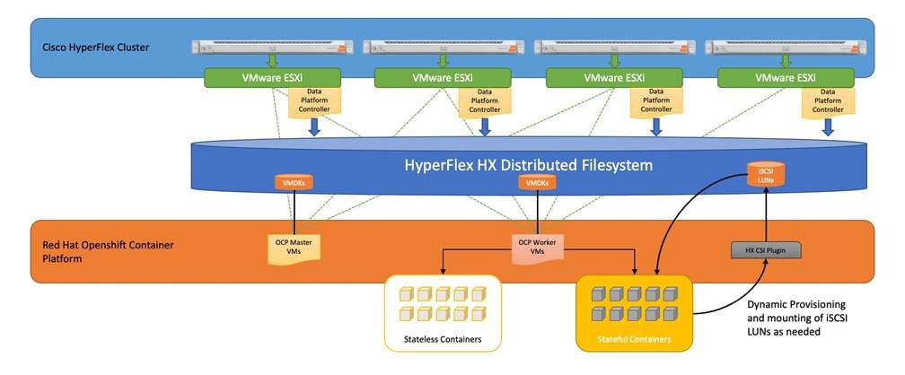
The following are the components of a standard (such as non-Edge) Cisco HyperFlex system using the VMware ESXi Hypervisor:
● One pair of Cisco UCS Fabric Interconnects, choose from models:
◦ Cisco UCS 6332 Fabric Interconnect
◦ Cisco UCS 6332-16UP Fabric Interconnect
◦ Cisco UCS 6454 Fabric Interconnect
◦ Cisco UCS 64108 Fabric Interconnect
● Three to Thirty-Two Cisco HyperFlex HX-Series Rack-Mount Servers, choose from models:
◦ Cisco HyperFlex HX220c-M5SX Rack-Mount Servers
◦ Cisco HyperFlex HX240c-M5SX Rack-Mount Servers
◦ Cisco HyperFlex HX240c-M5L Large Form-Factor Rack-Mount Servers (maximum of 16 nodes)
◦ Cisco HyperFlex HXAF220c-M5SX All-Flash Rack-Mount Servers
◦ Cisco HyperFlex HXAF240c-M5SX All-Flash Rack-Mount Servers
◦ Cisco HyperFlex HXAF220c-M5N All-NVMe Rack-Mount Servers
● Cisco HyperFlex Data Platform Software
● VMware vSphere ESXi Hypervisor
● VMware vCenter Server (end-user supplied)
Cisco HyperFlex Data Platform Software
The Cisco HyperFlex HX Data Platform is a purpose-built, high-performance, distributed file system with a wide array of enterprise-class data management services. The data platform’s innovations redefine distributed storage technology, exceeding the boundaries of first-generation hyperconverged infrastructures. The data platform has all the features expected in an enterprise shared storage system, eliminating the need to configure and maintain complex Fibre Channel storage networks and devices. The platform simplifies operations and helps ensure data availability. Enterprise-class storage features include the following:
● Data protection creates multiple copies of the data across the cluster so that data availability is not affected if single or multiple components fail (depending on the replication factor configured).
● Deduplication is always on, helping reduce storage requirements in virtualization clusters in which multiple operating system instances in guest virtual machines result in large amounts of replicated data.
● Compression further reduces storage requirements, reducing costs, and the log-structured file system is designed to store variable-sized blocks, reducing internal fragmentation.
● Replication copies virtual machine level snapshots from one Cisco HyperFlex cluster to another, to facilitate recovery from a cluster or site failure, via a failover to the secondary site of all VMs.
● Thin provisioning allows large volumes to be created without requiring storage to support them until the need arises, simplifying data volume growth and making storage a "pay as you grow" proposition.
● Fast, space-efficient clones rapidly duplicate virtual storage volumes so that virtual machines can be cloned simply through metadata operations, with actual data copied only for write operations.
● Snapshots help facilitate backup and remote-replication operations, which are needed in enterprises that require always-on data availability.
Cisco HyperFlex HX Data Platform Controller
A Cisco HyperFlex HX Data Platform controller resides on each node and implements the distributed file system. The controller runs as software in user space within a virtual machine, and intercepts and handles all I/O from the guest virtual machines. The Storage Controller Virtual Machine (SCVM) uses the VMDirectPath I/O feature to provide direct PCI passthrough control of the physical server’s SAS disk controller, or direct control of the PCI attached NVMe based SSDs. This method gives the controller VM full control of the physical disk resources, utilizing the SSD drives as a read/write caching layer, and the HDDs or SDDs as a capacity layer for distributed storage. The controller integrates the data platform into the VMware vSphere cluster through the use of three preinstalled VMware ESXi vSphere Installation Bundles (VIBs) on each node:
● scvmclient: This VIB, also called the HyperFlex IO Visor, provides a network file system (NFS) mount point so that the ESXi hypervisor can access the virtual disks that are attached to individual virtual machines. From the hypervisor’s perspective, it is simply attached to a network file system. The IO Visor intercepts guest VM IO traffic, and intelligently redirects it to the HyperFlex SCVMs.
● STFSNasPlugin: This VMware API for Array Integration (VAAI) storage offload API allows vSphere to request advanced file system operations such as snapshots and cloning. The controller implements these operations via manipulation of the filesystem metadata rather than actual data copying, providing rapid response, and thus rapid deployment of new environments.
● stHypervisorSvc: This VIB adds enhancements and features needed for HyperFlex data protection and VM replication.
Data Operations and Distribution
The Cisco HyperFlex HX Data Platform controllers handle all read and write operation requests from the guest VMs to their virtual disks (VMDK) stored in the distributed datastores in the cluster. The data platform distributes the data across multiple nodes of the cluster, and also across multiple capacity disks of each node, according to the replication level policy selected during the cluster setup. This method avoids storage hotspots on specific nodes, and on specific disks of the nodes, and thereby also avoids networking hotspots or congestion from accessing more data on some nodes versus others.
The policy for the number of duplicate copies of each storage block is chosen during cluster setup and is referred to as the replication factor (RF).
● Replication Factor 3: For every I/O write committed to the storage layer, 2 additional copies of the blocks written will be created and stored in separate locations, for a total of 3 copies of the blocks. Blocks are distributed in such a way as to ensure multiple copies of the blocks are not stored on the same disks, nor on the same nodes of the cluster. This setting can tolerate simultaneous failures of 2 entire nodes in a cluster of 5 nodes or greater, without losing data and resorting to restore from backup or other recovery processes. RF3 is recommended for all production systems and is the default for all clusters of 3 nodes or more.
● Replication Factor 2: For every I/O write committed to the storage layer, 1 additional copy of the blocks written will be created and stored in separate locations, for a total of 2 copies of the blocks. Blocks are distributed in such a way as to ensure multiple copies of the blocks are not stored on the same disks, nor on the same nodes of the cluster. This setting can tolerate a failure of 1 entire node without losing data and resorting to restore from backup or other recovery processes. RF2 is suitable for non-production systems, or environments where the extra data protection is not needed.
Data Write and Compression Operations
Internally, the contents of each guest VM's virtual disks are subdivided and spread across multiple servers by the HXDP software. For each write operation, the data is intercepted by the IO Visor module on the node where the VM is running, a primary node is determined for that particular operation via a hashing algorithm, and then sent to the primary node via the network. The primary node compresses the data in real time, writes the compressed data to the write log on its caching SSD, and replica copies of that compressed data are sent via the network and written to the write log on the caching SSD of the remote nodes in the cluster, according to the replication factor setting. For example, at RF=3 a write operation will be written to write log of the primary node for that virtual disk address, and two additional writes will be committed in parallel on two other nodes. Because the virtual disk contents have been divided and spread out via the hashing algorithm for each unique operation, this method results in all writes being spread across all nodes, avoiding the problems with data locality and "noisy" VMs consuming all the IO capacity of a single node. The write operation will not be acknowledged until all three copies are written to the caching layer SSDs. Written data is also cached in a write log area resident in memory in the controller VM, along with the write log on the caching SSDs. This process speeds up read requests when reads are requested of data that has recently been written.
Data Destaging and Deduplication
The Cisco HyperFlex HX Data Platform constructs multiple write log caching segments on the caching SSDs of each node in the distributed cluster. As write cache segments become full and based on policies accounting for I/O load and access patterns, those write cache segments are locked and new writes roll over to a new write cache segment. The data in the now locked cache segment is destaged to the HDD capacity layer of the nodes for the Hybrid system or to the SSD capacity layer of the nodes for the All-Flash systems. During the destaging process, data is deduplicated before being written to the capacity storage layer, and the resulting data can now be written to the HDDs or SDDs of the server. On hybrid systems, the now deduplicated and compressed data is also written to the dedicated read cache area of the caching SSD, which speeds up read requests of data that has recently been written. When the data is destaged to the capacity disks, it is written in a single sequential operation, avoiding disk head seek thrashing on the spinning disks and accomplishing the task in the minimal amount of time. Since the data is already deduplicated and compressed before being written, the platform avoids additional I/O overhead often seen on competing systems, which must later do a read/dedupe/compress/write cycle. Deduplication, compression and destaging take place with no delays or I/O penalties to the guest VMs making requests to read or write data, which benefits both the HDD and SDD configurations.
Figure 2. HyperFlex HX Data Platform Data Movement
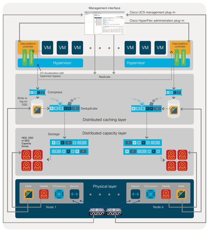
For data read operations, data may be read from multiple locations. For data that was very recently written, the data is likely to still exist in the write log of the local platform controller memory, or the write log of the local caching layer disk. If local write logs do not contain the data, the distributed filesystem metadata will be queried to see if the data is cached elsewhere, either in write logs of remote nodes, or in the dedicated read cache area of the local and remote caching SSDs of hybrid nodes. Finally, if the data has not been accessed in a significant amount of time, the filesystem will retrieve the requested data from the distributed capacity layer. As requests for reads are made to the distributed filesystem and the data is retrieved from the capacity layer, the caching SSDs of hybrid nodes populate their dedicated read cache area to speed up subsequent requests for the same data. This multi-tiered distributed system with several layers of caching techniques, ensures that data is served at the highest possible speed, leveraging the caching SSDs of the nodes fully and equally. All-flash configurations do not employ a dedicated read cache, because such caching does not provide any performance benefit since the persistent data copy already resides on high-performance SSDs.
In summary, the Cisco HyperFlex HX Data Platform implements a distributed, log-structured file system that performs data operations via two configurations:
● In a Hybrid configuration, the data platform provides a caching layer using SSDs to accelerate read requests and write responses, and it implements a storage capacity layer using HDDs.
● In an All-Flash configuration, the data platform provides a dedicated caching layer using high endurance SSDs to accelerate write responses, and it implements a storage capacity layer also using SSDs. Read requests are fulfilled directly from the capacity SSDs, as a dedicated read cache is not needed to accelerate read operations.
The Cisco HyperFlex product family can be divided logically into two families; a collection of hybrid nodes, and a collection of all-flash nodes. Hybrid converged nodes use a combination of solid-state disks (SSDs) for the short-term storage caching layer, and hard disk drives (HDDs) for the long-term storage capacity layer. The hybrid HyperFlex system is an excellent choice for entry-level or midrange storage solutions, and hybrid solutions have been successfully deployed in many non-performance sensitive virtual environments. Meanwhile, there is significant growth in deployment of highly performance sensitive and mission critical applications. The primary challenge to the hybrid HyperFlex system from these highly performance sensitive applications, is their increased sensitivity to high storage latency. Due to the characteristics of the spinning hard disks, it is unavoidable that their higher latency becomes the bottleneck in the hybrid system. Ideally, if all of the storage operations were to occur in the caching SSD layer, the hybrid system’s performance will be excellent. But in several scenarios, the amount of data being written and read exceeds the caching layer capacity, placing larger loads on the HDD capacity layer, and the subsequent increases in latency will naturally result in reduced performance.
Cisco All-Flash HyperFlex systems are an excellent option for customers with a requirement to support high performance, latency sensitive workloads. Because the capacity layer disks are also SSDs, the all-flash systems avoid the increased latency seen in hybrid nodes when larger amounts of data are written and read. With a purpose built, flash-optimized and high-performance log-based filesystem, the Cisco All-Flash HyperFlex system provides:
● Predictable high performance across all the virtual machines the cluster.
● Highly consistent and low latency, which benefits data-intensive applications.
● Future ready architecture that is well suited for flash-memory configuration:
◦ Cluster-wide SSD pooling maximizes performance and balances SSD usage so as to spread the wear.
◦ A fully distributed log-structured filesystem optimizes the data path to help reduce write amplification.
◦ Large sequential writing reduces flash wear and increases component longevity.
◦ Inline space optimization, for example deduplication and compression, minimizes data operations and reduces wear.
● Lower operating cost with the higher density drives for increased capacity of the system.
● Cloud scale solution with easy scale-out and distributed infrastructure and the flexibility of scaling out independent resources separately.
Cisco HyperFlex support for hybrid and all-flash models allows customers to choose the right platform configuration based on their capacity, applications, performance, and budget requirements. All-flash configurations offer repeatable and sustainable high performance, especially for scenarios with a larger working set of data, in other words, a large amount of data in motion. Hybrid configurations are a good option for customers who want the simplicity of the Cisco HyperFlex solution, but their needs focus on capacity-sensitive solutions, lower budgets, and fewer performance-sensitive applications.
Cisco Intersight Cloud Based Management
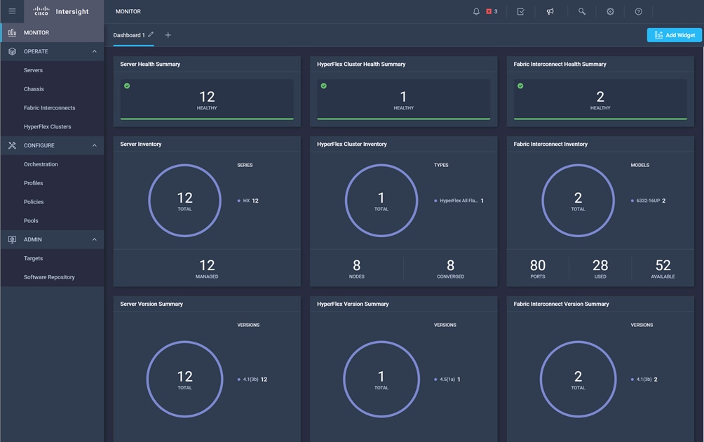
Cisco Intersight (https://intersight.com) is the latest visionary cloud-based management tool, designed to provide a centralized off-site management, monitoring, and reporting tool for all of your Cisco UCS based solutions, and can be used to deploy and manage Cisco HyperFlex clusters. Cisco Intersight offers direct links to Cisco UCS Manager and Cisco HyperFlex Connect for systems it is managing and monitoring. The Cisco Intersight website and framework is being constantly upgraded and extended with new and enhanced features independently of the products that are managed, meaning that many new features and capabilities can come with no downtime or upgrades required by the end users. This unique combination of embedded and online technologies results in a complete cloud-based management solution that can care for Cisco HyperFlex throughout the entire lifecycle, from deployment through retirement.
Figure 3. Cisco Intersight
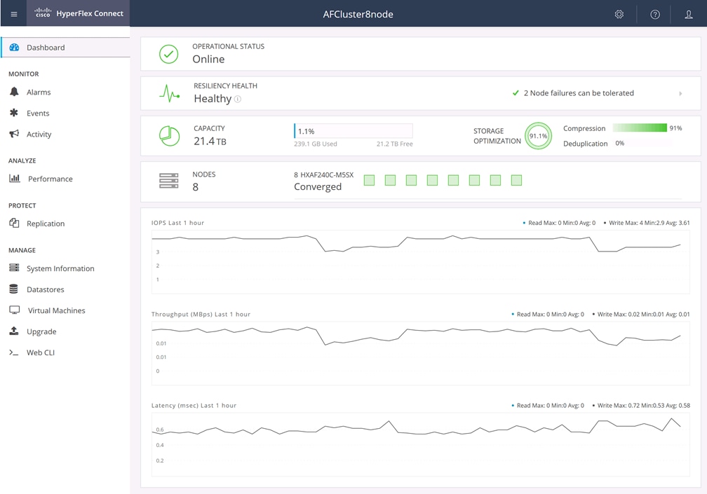
Cisco HyperFlex Connect HTML5 Management Web Page
An HTML 5 based Web UI named HyperFlex Connect is available for use as the primary management tool for Cisco HyperFlex. Through this centralized point of control for the cluster, administrators can create datastores, monitor the data platform health and performance, manage resource usage, and perform upgrades. Administrators can also use this management portal to predict when the cluster will need to be scaled, create VM snapshot schedules and configure native VM replication. To use the HyperFlex Connect UI, connect using a web browser to the HyperFlex cluster IP address: http://<hx controller cluster ip>.
Figure 4. HyperFlex Connect GUI
Red Hat OpenShift Container Platform
The Red Hat OpenShift Container Platform (RHOCP) is a platform for developing, deploying and running containerized applications. It is a scalable architecture designed to expand anywhere from small deployments to large platforms supporting users globally. Based on open Red Hat technologies, RHOCP clusters enable a cloud-native ecosystem which can grow beyond a single private on-premise cloud, to hybrid and multi-cloud environments. RHOCP is a container application platform that brings together Kubernetes, the defacto standard for containerized orchestration, plus CRI-O, and provides an API and web interface to manage these services. CRI-O is an implementation of the Kubernetes CRI (Container Runtime Interface) to enable using Open Container Initiative (OCI) compatible runtimes. It is a lightweight alternative to using Docker as the runtime for Kubernetes.
RHOCP allows customers to create and manage containers. Containers use small, dedicated Linux operating systems without their own kernel. Their file system, networking, cgroups, process tables, and namespaces are separate from the host Linux system. Because each container runs in a unique and dedicated process space, applications which have conflicting software dependencies can run on the same host. Containers manage their own software dependencies, their own networking interfaces and file systems, so applications running as containers do not compete for those system resources.
RHOCP helps developing, deploying, and managing container-based applications. It provides a self-service platform to create, modify, and deploy applications on demand, thus enabling faster development and release life cycles. RHOCP has a microservices-based architecture of smaller, decoupled units that work together. It runs on top of a Kubernetes cluster, with data about the objects stored in etcd, a reliable clustered key-value store.
Figure 5. Red Hat OpenShift Container Platform Overview
Within Red Hat OpenShift Container Platform, Kubernetes manages containerized applications across a set of CRI-O runtime hosts and provides mechanisms for deployment, maintenance, and application-scaling. The CRI-O service packages, instantiates, and runs containerized applications.
A Kubernetes cluster consists of one or more masters and a set of worker nodes. This solution design includes HA functionality at the hardware as well as the software stack. A Kubernetes cluster is designed to run in HA mode with 3 master nodes and a minimum of 2 worker nodes to help ensure that the cluster has no single point of failure.
The smallest deployable unit in a Kubernetes cluster is called a pod. A pod is simply a collection of one or more containers, with shared network and file resources, along with a YAML file descriptor. Pods commonly consist of a single containerized application or service, but can also contain multiple containers which need to be tightly coupled, with common resources.
Red Hat Enterprise Linux Core OS
Red Hat OpenShift Container Platform uses Red Hat Enterprise Linux CoreOS (RHCOS), a container-optimized operating system that combines some of the best features and functions of the Red Hat Enterprise Linux CoreOS and Red Hat Enterprise Linux Atomic Host operating systems. RHCOS is specifically designed for running containerized applications from Red Hat OpenShift Container Platform and works with new tools to provide fast installation, Operator-based management, and simplified upgrades.
RHCOS includes:
● Ignition, which Red Hat OpenShift Container Platform uses as a first boot system configuration for initially bringing up and configuring machines.
● CRI-O, a Kubernetes native container runtime implementation that integrates closely with the operating system to deliver an efficient and optimized Kubernetes experience. CRI-O provides facilities for running, stopping, and restarting containers. It fully replaces the Docker Container Engine, which was used in Red Hat OpenShift Container Platform 3.
● Kubelet, the primary node agent for Kubernetes that is responsible for launching and monitoring containers.
In the solution presented in this document, RHCOS was used on all control plane and worker nodes to support an automated RHOCP 4.9 deployment.
A standard HyperFlex cluster requires a minimum of three HX-Series “converged” nodes (such as nodes with shared disk storage). Data is replicated across at least two of these nodes, and a third node is required for continuous operation in the event of a single-node failure. Each node that has disk storage is equipped with at least one high-performance SSD drive for data caching and rapid acknowledgment of write requests. Each node also is equipped with additional disks, up to the platform’s physical limit, for long term storage and capacity.
The Cisco UCS Fabric Interconnect (FI) is a core part of the Cisco Unified Computing System, providing both network connectivity and management capabilities for the system. Depending on the model chosen, the Cisco UCS Fabric Interconnect offers line-rate, low-latency, lossless Ethernet, Fibre Channel over Ethernet (FCoE) and Fibre Channel connectivity. Cisco UCS Fabric Interconnects provide the management and communication backbone for the Cisco UCS C-Series, S-Series and HX-Series Rack-Mount Servers, Cisco UCS B-Series Blade Servers, and Cisco UCS 5100 Series Blade Server Chassis. All servers and chassis, and therefore all blades, attached to the Cisco UCS Fabric Interconnects become part of a single, highly available management domain. In addition, by supporting unified fabrics, the Cisco UCS Fabric Interconnects provide both the LAN and SAN connectivity for all servers within its domain. The product family supports Cisco low-latency, lossless Ethernet unified network fabric capabilities, which increase the reliability, efficiency, and scalability of Ethernet networks. The Fabric Interconnect supports multiple traffic classes over the Ethernet fabric from the servers to the uplinks. Significant TCO savings come from an FCoE-optimized server design in which network interface cards (NICs), host bus adapters (HBAs), cables, and switches can be consolidated.
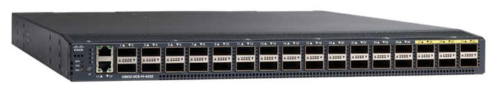
Cisco UCS 6332 Fabric Interconnect
The Cisco UCS 6332 Fabric Interconnect is a one-rack-unit (1RU) 40 Gigabit Ethernet and FCoE switch offering up to 2560 Gbps of throughput. The switch has 32 40-Gbps fixed Ethernet and FCoE ports. Up to 24 of the ports can be reconfigured as 4x10Gbps breakout ports, providing up to 96 10-Gbps ports, although Cisco HyperFlex nodes must use a 40GbE VIC adapter in order to connect to a Cisco UCS 6300 Series Fabric Interconnect.
Figure 6. Cisco UCS 6332 Fabric Interconnect
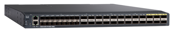
Cisco UCS 6332-16UP Fabric Interconnect
The Cisco UCS 6332-16UP Fabric Interconnect is a one-rack-unit (1RU) 10/40 Gigabit Ethernet, FCoE, and native Fibre Channel switch offering up to 2430 Gbps of throughput. The switch has 24 40-Gbps fixed Ethernet and FCoE ports, plus 16 1/10-Gbps fixed Ethernet, FCoE, or 4/8/16 Gbps FC ports. Up to 18 of the 40-Gbps ports can be reconfigured as 4x10Gbps breakout ports, providing up to 88 total 10-Gbps ports, although Cisco HyperFlex nodes must use a 40GbE VIC adapter in order to connect to a Cisco UCS 6300 Series Fabric Interconnect.
Figure 7. Cisco UCS 6332-16UP Fabric Interconnect
![]() When used for a Cisco HyperFlex deployment, due to mandatory QoS settings in the configuration, the 6332 and 6332-16UP will be limited to a maximum of four 4x10Gbps breakout ports, which can be used for other non-HyperFlex servers.
When used for a Cisco HyperFlex deployment, due to mandatory QoS settings in the configuration, the 6332 and 6332-16UP will be limited to a maximum of four 4x10Gbps breakout ports, which can be used for other non-HyperFlex servers.
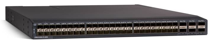
Cisco UCS 6454 Fabric Interconnect
The Cisco UCS 6454 Fabric Interconnect is a One-Rack-Unit (1RU) 10/25/40/100 Gigabit Ethernet, FCoE and Fibre Channel switch offering up to 3.82 Tbps throughput and up to 54 ports. The switch has 28 10/25-Gbps Ethernet ports, 4 1/10/25-Gbps Ethernet ports, 6 40/100-Gbps Ethernet uplink ports and 16 unified ports that can support 10/25-Gbps Ethernet ports or 8/16/32-Gbps Fibre Channel ports. All Ethernet ports are capable of supporting FCoE. Cisco HyperFlex nodes can connect at 10-Gbps or 25-Gbps speeds depending on the model of Cisco VIC card in the nodes and the SFP optics or cables chosen.
Figure 8. Cisco UCS 6454 Fabric Interconnect
Cisco UCS 64108 Fabric Interconnect
The Cisco UCS 64108 Fabric Interconnect is a Two-Rack-Unit (2RU) 10/25/40/100 Gigabit Ethernet, FCoE and Fibre Channel switch offering up to 7.42 Tbps throughput and up to 108 ports. The switch has 72 10/25-Gbps Ethernet ports, 8 1/10/25-Gbps Ethernet ports, 12 40/100-Gbps Ethernet uplink ports and 16 unified ports that can support 10/25-Gbps Ethernet ports or 8/16/32-Gbps Fibre Channel ports. All Ethernet ports are capable of supporting FCoE. Cisco HyperFlex nodes can connect at 10-Gbps or 25-Gbps speeds depending on the model of Cisco VIC card in the nodes and the SFP optics or cables chosen.
Figure 9. Cisco UCS 64108 Fabric Interconnect
Cisco HyperFlex HXAF220c-M5N All-NVMe Node
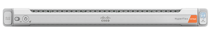
This small footprint (1RU) Cisco HyperFlex all-NVMe model contains one or two 240 GB or 960 GB M.2 form factor solid-state disks (SSD) that acts as the boot drive. When two boot drives are ordered the optional HX-M2-HWRAID controller must be included to enable RAID 1 boot drive redundancy. A 1 TB housekeeping NVMe SSD drive, a single 375 GB Intel Optane NVMe SSD write-log drive, and six to eight 1 TB, 4 TB or 8 TB NVMe SSD drives are included for storage capacity. Optionally, the Cisco HyperFlex Acceleration Engine card can be added to improve write performance and compression. Either Cisco VIC model 1457 quad-port 10/25 Gb, or model 1387 dual-port 40 Gb card may be selected. Self-encrypting drives are not available as an option for the all-NVMe nodes.
Figure 10. HXAF220c-M5N All-Flash Node

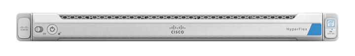
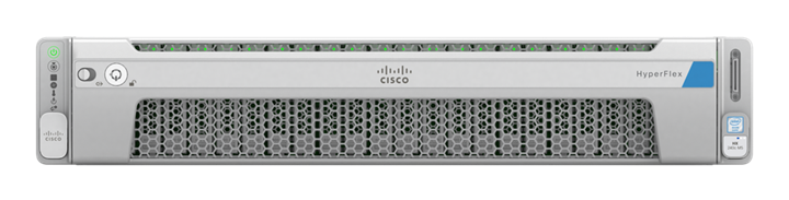
Cisco HyperFlex HXAF220c-M5SX All-Flash Node
This small footprint (1RU) Cisco HyperFlex all-flash model contains one or two 240 GB or 960 GB M.2 form factor solid-state disks (SSD) that acts as the boot drive. When two boot drives are ordered the optional HX-M2-HWRAID controller must be included to enable RAID 1 boot drive redundancy. A 240 GB housekeeping SSD drive, either a single 375 GB Optane NVMe SSD, a 1.6 TB NVMe SSD, an 800 GB SAS SSD or 1.6 TB SAS SSD write-log drive, and six to eight 960 GB, 3.8 TB or 7.6 TB SATA SSD drives are included for storage capacity. For configurations requiring self-encrypting drives, the caching SSD is replaced with an 800 GB SAS SED SSD, and the capacity disks are also replaced with 960 GB, 3.8 TB or 7.6 TB SAS SED SSDs. Either Cisco VIC model 1457 quad-port 10/25 Gb, or model 1387 dual-port 40 Gb card may be selected. Optionally, the Cisco HyperFlex Acceleration Engine card can be added to improve write performance and compression.
Figure 11. HXAF220c-M5SX All-Flash Node
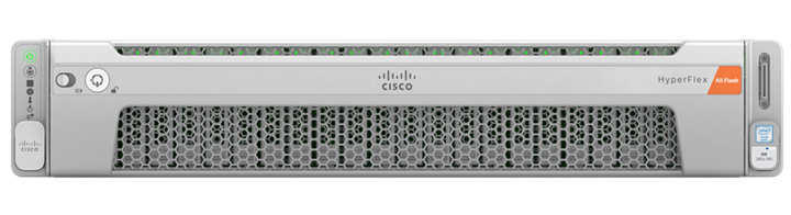
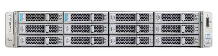
Cisco HyperFlex HXAF240c-M5SX All-Flash Node
This capacity optimized (2RU) Cisco HyperFlex all-flash model contains one or two 240 GB or 960 GB M.2 form factor solid-state disks (SSD) that acts as the boot drive. When two boot drives are ordered the optional HX-M2-HWRAID controller must be included to enable RAID 1 boot drive redundancy. A 240 GB housekeeping SSD drive, either a single 375 GB Optane NVMe SSD, a 1.6 TB NVMe SSD, an 800 GB SAS SSD or 1.6 TB SAS SSD write-log drive, and six to twenty-three 960 GB, 3.8 TB or 7.6 TB SATA SSD drives are included for storage capacity. For configurations requiring self-encrypting drives, the caching SSD is replaced with an 800 GB SAS SED SSD, and the capacity disks are also replaced with 960 GB, 3.8 TB or 7.6 TB SAS SED SSDs. Either Cisco VIC model 1457 quad-port 10/25 Gb, or model 1387 dual-port 40 Gb card may be selected. Optionally, the Cisco HyperFlex Acceleration Engine card can be added to improve write performance and compression.
Figure 12. HXAF240c-M5SX Node
Cisco HyperFlex HX220c-M5SX Hybrid Node
This small footprint (1RU) Cisco HyperFlex hybrid model contains one or two 240 GB or 960 GB M.2 form factor solid-state disks (SSD) that acts as the boot drive. When two boot drives are ordered the optional HX-M2-HWRAID controller must be included to enable RAID 1 boot drive redundancy. A 240 GB housekeeping SSD drive, either a single 480 GB SATA SSD or 800 GB SAS SSD write-log drive, and six to eight 1.2 TB, 1.8 TB or 2.4 TB SAS SSD drives are included for storage capacity. For configurations requiring self-encrypting drives, the caching SSD is replaced with an 800 GB SAS SED SSD, and the capacity disks are also replaced with 1.2 TB or 2.4 TB SAS SED SSDs. Either Cisco VIC model 1457 quad-port 10/25 Gb, or model 1387 dual-port 40 Gb card may be selected. Optionally, the Cisco HyperFlex Acceleration Engine card can be added to improve write performance and compression.
Figure 13. HX220c-M5SX Node
Cisco HyperFlex HX240c-M5SX Hybrid Node
This capacity optimized (2RU) Cisco HyperFlex hybrid model contains one or two 240 GB or 960 GB M.2 form factor solid-state disks (SSD) that acts as the boot drive. When two boot drives are ordered the optional HX-M2-HWRAID controller must be included to enable RAID 1 boot drive redundancy. A 240 GB housekeeping SSD drive, a single 1.6 TB SAS SSD write-log drive, and six to twenty-three 1.2 TB, 1.8 TB or 2.4 TB SAS SSD drives are included for storage capacity. For configurations requiring self-encrypting drives, the caching SSD is replaced with a 1.6 TB SAS SED SSD, and the capacity disks are also replaced with 1.2 TB or 2.4 TB SAS SED SSDs. Either Cisco VIC model 1457 quad-port 10/25 Gb, or model 1387 dual-port 40 Gb card may be selected. Optionally, the Cisco HyperFlex Acceleration Engine card can be added to improve write performance and compression.
Figure 14. HX240c-M5SX Node
Cisco HyperFlex HX240c-M5L Hybrid Node
This density optimized (2RU) Cisco HyperFlex hybrid model contains one or two 240 GB or 960 GB M.2 form factor solid-state disks (SSD) that acts as the boot drive. When two boot drives are ordered the optional HX-M2-HWRAID controller must be included to enable RAID 1 boot drive redundancy. A 240 GB housekeeping SSD drive, a single 3.2 TB SAS SSD write-log drive, and six to twelve 6 TB, 8 TB or 12 TB 7.2K RPM large-form-factor (LFF) SAS SSD drives are included for storage capacity. Either Cisco VIC model 1457 quad-port 10/25 Gb, or model 1387 dual-port 40 Gb card may be selected. Optionally, the Cisco HyperFlex Acceleration Engine card can be added to improve write performance and compression. Large form factor nodes cannot be configured with self-encrypting disks.
Figure 15. HX240c-M5L Node
For complete server specifications and more information, please refer to the links below:
Compare Models:
HXAF220c-M5SN Spec Sheet:
HXAF220c-M5SX Spec Sheet:
HXAF240c-M5SX Spec Sheet:
HX220c-M5SX Spec Sheet:
HX240c-M5SX Spec Sheet:
HX240c-M5L Spec Sheet:
Cisco VIC 1387 and 1457 MLOM Interface Cards
The mLOM slot is used to install a Cisco VIC without consuming a PCIe slot, which provides greater I/O expandability. It incorporates next-generation converged network adapter (CNA) technology from Cisco, providing investment protection for future feature releases. The card enables a policy-based, stateless, agile server infrastructure that can present up to 256 PCIe standards-compliant interfaces to the host, each dynamically configured as either a network interface card (NICs) or host bus adapter (HBA). The personality of the interfaces is set programmatically using the service profile associated with the server. The number, type (NIC or HBA), identity (MAC address and World Wide Name [WWN]), failover policy, adapter settings, bandwidth, and quality-of-service (QoS) policies of the PCIe interfaces are all specified using the service profile.
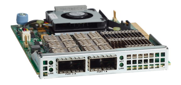
The Cisco UCS VIC 1387 Card is a dual-port Enhanced Quad Small Form-Factor Pluggable (QSFP+) 40-Gbps Ethernet and Fibre Channel over Ethernet (FCoE)-capable PCI Express (PCIe) modular LAN-on-motherboard (mLOM) adapter installed in the Cisco UCS HX-Series Rack Servers. The Cisco UCS VIC 1387 is used in conjunction with the Cisco UCS 6332 or 6332-16UP model Fabric Interconnects.
Figure 16. Cisco VIC 1387 mLOM Card
![]() Hardware revision V03 or later of the Cisco VIC 1387 card is required for the Cisco HyperFlex HX-series servers.
Hardware revision V03 or later of the Cisco VIC 1387 card is required for the Cisco HyperFlex HX-series servers.
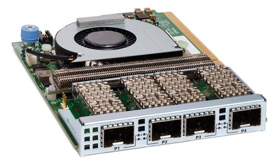
The Cisco UCS VIC 1457 is a quad-port Small Form-Factor Pluggable (SFP28) mLOM card designed for the M5 generation of Cisco UCS HX-Series Rack Servers. The card supports 10-Gbps or 25-Gbps Ethernet and FCoE, where the speed of the link is determined by the model of SFP optics or cables used. The card can be configured to use a pair of single links, or optionally to use all four links as a pair of bonded links. The Cisco UCS VIC 1457 is used in conjunction with the Cisco UCS 6454 model Fabric Interconnect.
Figure 17. Cisco VIC 1457 mLOM Card
In most circumstances, the choice between the Cisco UCS VIC 1387 and Cisco UCS VIC 1457 will be made automatically based upon the model of Fabric Interconnect the Cisco HX-series servers will be connected to. In general, 10-Gbps ethernet links will not be saturated with HXDP storage traffic, especially for clusters running only hybrid nodes. For all-flash and all-NVMe clusters, it is recommended to use the Cisco UCS VIC 1457 in 25-Gbps mode by pairing it with 25-Gbps twinax cables or optical connectors, or to use the Cisco UCS VIC 1387 at 40-Gbps.
The Cisco HyperFlex system is composed of three to thirty-two HX-Series rack-mount servers per cluster. The servers connect to the network via 10Gb, 25Gb or 40Gb converged Ethernet connections via a pair of Cisco UCS Fabric Interconnects.
Figure 18. HyperFlex Cluster Topology

The software components of the Cisco HyperFlex system must meet minimum requirements for the Cisco UCS firmware, hypervisor version, and the Cisco HyperFlex Data Platform software in order to interoperate properly.
For additional hardware and software combinations, refer to the public Cisco UCS Hardware Compatibility webpage: https://ucshcltool.cloudapps.cisco.com/public/
Table 1 lists the software components and the versions required for the Cisco HyperFlex 4.5 system, and the additional software for the testing of this solution.
| Component |
Software Required |
| Hypervisor |
6.5 U3, 6.7 U3, 7.0 U1c (build 17325551) through 7.0 U1d (build 17551050), 7.0 U2
CISCO Custom Image for ESXi 7.0 Update 2a for HyperFlex: HX-ESXi-7.0U2-17867351-Cisco-Custom-7.2.0.5-install-only.iso |
| Management Server |
VMware vCenter 6.5 U3, 6.7 U3, 7.0 U1c (build 17327517) through 7.0 U1d (build 17491101), 7.0 U2 Refer to http://www.vmware.com/resources/compatibility/sim/interop_matrix.php for interoperability of your ESXi version and vCenter Server. |
| Cisco UCS Firmware |
Cisco UCS 4.1(3f) |
| Cisco HyperFlex |
Cisco HyperFlex HX Data Platform Software 4.5(2a) or later |
| Cisco HyperFlex CSI Plugin |
Cisco HXCSI plugin version 1.2.4 or later |
| Red Hat OpenShift Container Platform |
Red Hat OpenShift Container Platform 4.9 or later |
Cisco HyperFlex systems must be properly licensed using Cisco Smart Licensing, which is a cloud-based software licensing management solution used to automate many manual, time consuming and error prone licensing tasks. Cisco HyperFlex 2.5 and later communicate with the Cisco Smart Software Manager (CSSM) online service via a Cisco Smart Account, to check out or assign available licenses from the account to the Cisco HyperFlex cluster resources. Communications can be direct via the internet, they can be configured to communicate via a proxy server, or they can communicate with an internal Cisco Smart Software Manager satellite server, which caches and periodically synchronizes licensing data. In a small number of highly secure environments, systems can be provisioned with a Permanent License Reservation (PLR) which does not need to communicate with CSSM. Contact your Cisco sales representative or partner to discuss if your security requirements will necessitate use of these permanent licenses. New HyperFlex cluster installations will operate for 90 days without licensing as an evaluation period, thereafter the system will generate alarms and operate in a non-compliant mode. Systems without compliant licensing will not be entitled to technical support.
For more information on the Cisco Smart Software Manager satellite server, visit this website: https://www.cisco.com/c/en/us/buy/smart-accounts/software-manager-satellite.html
Beginning with Cisco HyperFlex 4.5, licensing of the system requires one license per node from one of two different licensing editions; HyperFlex Datacenter Advantage or Datacenter Premier. Depending on the type of cluster being installed, and the desired features to be activated and used in the system, licenses must be purchased from the appropriate licensing tier. Additional features in the future will be added to the different licensing editions as they are released, the features listed below are current only as of the publication of this document.
Table 2 lists an overview of the licensing editions, and the features available with each type of license.
Table 2. HyperFlex System License Editions
| HyperFlex Licensing Edition |
Datacenter Advantage |
Datacenter Premier (in addition to Advantage) |
| Features Available |
HyperFlex standard clusters with Fabric Interconnects 220 and 240 SFF all-flash and hybrid server models 240 LFF server models NVMe caching disks iSCSI HX Native Replication Hyper-V and Kubernetes platforms Cluster expansions Compute-only nodes up to 1:1 ratio 10 Gb, 25 Gb or 40 Gb Ethernet Data-at-rest encryption using self-encrypting disks Logical Availability Zones |
Stretched clusters 220 all-NVMe server models Cisco HyperFlex Acceleration Engine cards Compute-only nodes up to 2:1 ratio |
For a comprehensive guide to licensing and all the features in each edition, consult the Cisco HyperFlex Licensing Guide here: https://www.cisco.com/c/en/us/td/docs/hyperconverged_systems/HyperFlex_HX_DataPlatformSoftware/b_Cisco_HyperFlex_Systems_Ordering_and_Licensing_Guide/b_Cisco_HyperFlex_Systems_Ordering_and_Licensing_Guide_chapter_01001.html
The software revisions listed in Table 7 are the only valid and supported configuration at the time of the publishing of this validated design. Special care must be taken not to alter the revision of the hypervisor, vCenter server, Cisco HX platform software, or the Cisco UCS firmware without first consulting the appropriate release notes and compatibility matrixes to ensure that the system is not being modified into an unsupported configuration.
The following best practice guidance applies to installations of HyperFlex 4.5:
● Do not modify the default TCP port settings of the vCenter installation. Using non-standard ports can lead to failures during the installation.
● It is recommended to build the vCenter server on a physical server or as a virtual machine in a virtual environment outside of the HyperFlex cluster. Building the vCenter server as a virtual machine inside the HyperFlex cluster environment is discouraged. There is a tech note for multiple methods of deployment if no external vCenter server is already available: http://www.cisco.com/c/en/us/td/docs/hyperconverged_systems/HyperFlex_HX_DataPlatformSoftware/TechNotes/Nested_vcenter_on_hyperflex.html
![]() This document does not cover the installation and configuration of VMware vCenter Server for Windows, or the vCenter Server Appliance.
This document does not cover the installation and configuration of VMware vCenter Server for Windows, or the vCenter Server Appliance.
Cisco HyperFlex standard clusters currently scale from a minimum of 3 to a maximum of 32 Cisco HX-series converged nodes with small form factor (SFF) disks per cluster. A converged node is a member of the cluster which provides storage resources to the HX Distributed Filesystem. For the compute intensive “extended” cluster design, a configuration with 3 to 32 Cisco HX-series converged nodes can be combined with up to 32 compute nodes. It is required that the number of compute-only nodes should always be less than or equal to number of converged nodes when using the HyperFlex Datacenter Advantage licenses. If using HyperFlex Datacenter Premier licenses, the number of compute-only nodes can grow to as much as twice the number of converged nodes. Regardless of the licensing used, the combined maximum size of any HyperFlex cluster cannot exceed 64 nodes. Once the maximum size of a single cluster has been reached, the environment can be “scaled out” by adding additional HX model servers to the Cisco UCS domain, installing an additional HyperFlex cluster on those new servers, and controlling them via the same vCenter server. There is no limit to the number of clusters that can be created in a single UCS domain, the practical limits will instead be reached due to the number of ports available on the Fabric Interconnects. Up to 100 HyperFlex clusters can be managed by a single vCenter server. When using Cisco Intersight for management and monitoring of Cisco HyperFlex clusters, there are no practical limits to the number of clusters being managed.
Cisco HyperFlex HX240c-M5L model servers with large form factor (LFF) disks are limited to a maximum of sixteen nodes per cluster and cannot be mixed within the same cluster as models with small form factor (SFF) disks. In the case where the HX240c-M5L nodes use the 12 TB capacity disks, the maximum number of converged nodes is limited to 8.
Cisco HyperFlex systems deployed in a stretched cluster configuration require a minimum of two Cisco HX-series converged nodes per physical site and support a maximum of sixteen converged nodes per physical site when using small-form-factor (SFF) disks. When using large-form-factor (LFF) disks, the maximum number of converged nodes allowed in a stretched cluster is 8. Each site requires a pair of Cisco UCS Fabric Interconnects, to form an individual UCS domain in both sites.
Table 3 lists the minimum and maximum scale for various installations of the Cisco HyperFlex system.
Table 3. HyperFlex Cluster Scale
| Cluster Type |
Minimum Converged Nodes Required |
Maximum Converged Nodes |
Maximum Compute-only Nodes Allowed |
Maximum Total Cluster Size |
| Standard with SFF flash or all-NVMe disks |
3 |
32 |
32 |
64 |
| Standard with LFF disks |
3 |
16 |
32 |
48 |
| Standard with 12 TB LFF disks |
3 |
8 |
16 |
24 |
| Stretched with SFF disks |
2 per site |
16 per site |
21 per site |
32 per site 64 per cluster |
| Stretched with LFF disks |
2 per site |
8 per site |
16 per site |
24 per site 48 per cluster |
Capacity
Overall usable cluster capacity is based on a number of factors. The number of nodes in the cluster, the number and size of the capacity layer disks, and the replication factor of the HyperFlex HX Data Platform, all affect the cluster capacity. In addition, configuring a cluster as a stretched cluster across two sites modifies the data distribution method, which reduces capacity in favor of data availability. Caching disk sizes are not calculated as part of the cluster capacity.
Table 4 lists a set of HyperFlex HX Data Platform cluster usable capacity values, using binary prefix, for an array of cluster configurations. These values provide an example of the capacity calculations, for determining the appropriate size of HX cluster to initially purchase, and how much capacity can be gained by adding capacity disks.
Table 4. Cluster Usable Capacities
| HX-Series Server Model |
Node Quantity |
Capacity Disk Size (each) |
Capacity Disk Quantity (per node) |
Cluster Usable Capacity at RF=2 |
Cluster Usable Capacity at RF=3 |
| HXAF220c-M5SX |
8 |
3.8 TB |
8 |
102.8 TiB |
68.6 TiB |
| 960 GB |
8 |
25.7 TiB |
17.1 TiB |
||
| HXAF240c-M5SX |
8 |
3.8 TB |
6 |
77.1 TiB |
51.4 TiB |
| 15 |
192.8 TiB |
128.5 TiB |
|||
| 23 |
295.7 TiB |
197.1 TiB |
|||
| 960 GB |
6 |
19.3 TiB |
12.9 TiB |
||
| 15 |
48.2 TiB |
32.1 TiB |
|||
| 23 |
73.9 TiB |
49.3 TiB |
|||
| HX240c-M5L |
8 |
6 TB |
6 |
120.5 TiB |
80.3 TiB |
| 12 |
241.0 TiB |
160.7 TiB |
|||
| 8 TB |
6 |
160.7 TiB |
107.1 TiB |
||
| 12 |
321.3 TiB |
214.2 TiB |
![]() Capacity calculations methods for all servers are identical regardless of model. Calculations are based upon the number of nodes, the number of capacity disks per node, and the size of the capacity disks. Table 4 is not a comprehensive list of all capacities and models available.
Capacity calculations methods for all servers are identical regardless of model. Calculations are based upon the number of nodes, the number of capacity disks per node, and the size of the capacity disks. Table 4 is not a comprehensive list of all capacities and models available.
Installing the HyperFlex system is done via the Cisco Intersight online management portal, or through a deployable HyperFlex installer virtual machine, available for download at cisco.com as an OVA file. The installer performs the configuration of Cisco UCS Manager, the physical servers, and also performs significant portions of the ESXi configuration. Finally, the installer will install the HyperFlex HX Data Platform software and create the HyperFlex cluster. Because detailed information regarding the design and installation of Cisco HyperFlex are available in existing Cisco Validated Design documents, links to those documents will be provided, and a general overview of the Cisco HyperFlex environment will be described. Red Hat OpenShift Container Platform installation design elements, which are layered on top of the Cisco HyperFlex cluster will be presented to improve knowledge and understanding of the combination of these two technologies.
Cisco HyperFlex Logical Network Design
Cisco HyperFlex clusters can be installed with the choice between 10Gb, 25Gb and 40Gb Ethernet bandwidth, with two connections per server to the dual redundant upstream Fabric Interconnects.
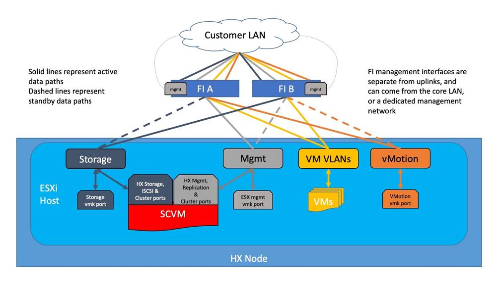
The Cisco HyperFlex system has communication pathways that fall into four defined zones (Figure 19):
● Management Zone: This zone comprises the connections needed to manage the physical hardware, the hypervisor hosts, and the storage platform controller virtual machines (SCVM).
● VM Zone: This zone comprises the connections needed to service network IO to the guest VMs that will run inside the HyperFlex hyperconverged system. This zone typically contains multiple routable VLANs, which are trunked to the Cisco UCS Fabric Interconnects via the network uplinks and tagged with 802.1Q VLAN IDs. For the Red Hat OpenShift Container Platform installation, the RHOCP master and worker VMs' networking endpoints would reside in this zone.
● Storage Zone: This zone comprises the connections used by the Cisco HX Data Platform software, ESXi hosts, and the storage controller VMs to service the HX Distributed Data Filesystem. The HX storage VLAN does not need to be routable to the rest of the LAN, however it must be able to traverse the switches upstream from the Fabric Interconnects. In addition, a VLAN for iSCSI-based traffic is created in this zone, which may or may not be routable according to the network design. Within this VLAN, the iSCSI storage IP addresses, one per node and one for the entire cluster, are created for presenting HXDP storage to external clients via the iSCSI protocol. These addresses are used in this design by the stateful containers which mount iSCSI-based volumes using the HX CSI plugin.
● VMotion Zone: This zone comprises the connections used by the ESXi hosts to enable vMotion of the guest VMs from host to host.
Figure 19. Logical Network Design
Red Hat OpenShift Container Platform Logical Networking Design
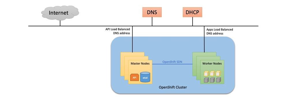
Red Hat OpenShift Container Platform utilizes software-defined networking (SDN) to create a unified pod network for the containers to communicate with each other. This overlay network, based on Open vSwitch (OVS), assigns one IP address per pod from the pod network. Each container within a pod behaves as though they were on the same physical host, and each pod can communicate with the others via the pod network. With this logical design, a pod can be thought of as nearly analogous to a VM, with its own addressing, ports, naming, load balancing and service discovery.
Figure 20. Red Hat OpenShift Logical Network Design
Red Hat OpenShift Cluster Network
The Pod network, also called the cluster network, is established and maintained by the OpenShift SDN, which configures an overlay network using Open vSwitch (OVS). OpenShift SDN provides three SDN plug-ins for configuring the pod network:
● The ovs-subnet plug-in is the original plug-in, which provides a "flat" pod network where every pod can communicate with every other pod and service.
● The ovs-multitenant plug-in provides project-level isolation for pods and services. Each project receives a unique Virtual Network ID (VNID) that identifies traffic from pods assigned to the project. Pods from different projects cannot send packets to or receive packets from pods and services of a different project.
● The ovs-networkpolicy plug-in allows project administrators to configure their own isolation policies using NetworkPolicy objects.
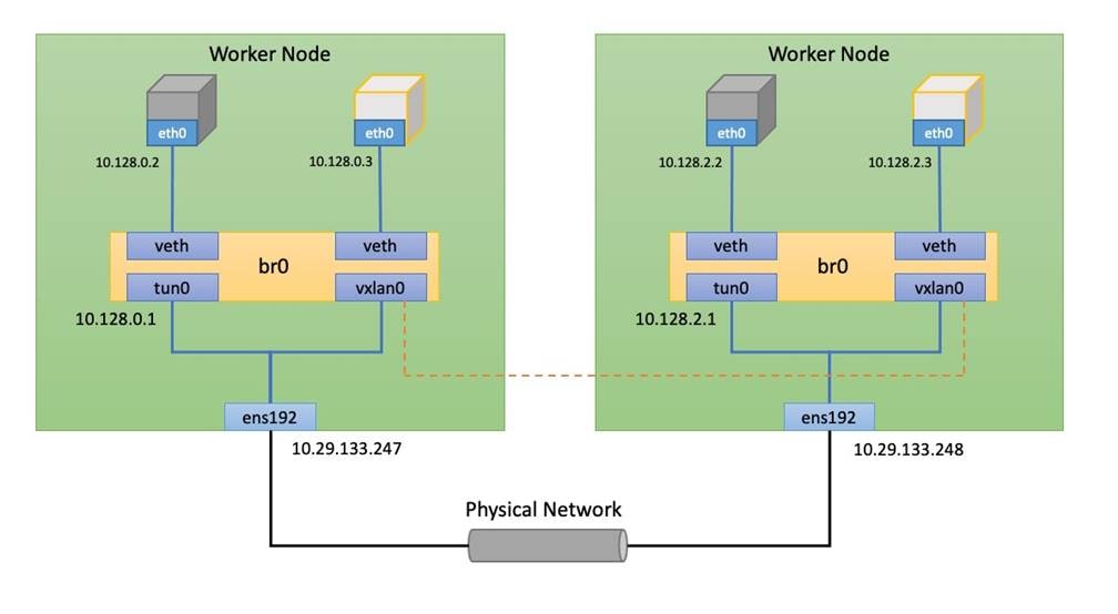
OpenShift SDN maintains a registry of all nodes in the cluster, stored in etcd. When a master or worker node is registered, OpenShift SDN allocates an unused /23 subnet from the cluster network and stores this subnet in the registry. Removing or deleting a node from the cluster frees the corresponding cluster network subnet. In the default configuration, the cluster network is the 10.128.0.0/14 network (such as, 10.128.0.0 - 10.131.255.255), and nodes are each allocated a /23 subnet (such as 10.128.0.0/23, 10.128.2.0/23, 10.128.4.0/23, and so on). This means that the cluster network has 512 subnets available to assign to nodes, and a given node is allocated 510 addresses that it can assign to the pods running on it. The size and address range of the cluster network are configurable, as is the host subnet size.
As additional subnet is created and managed by OpenShift SDN for network services, called the service network. By default, this network uses the 172.30.0.0/16 subnet.
In addition to the native ethernet device of the node, ens192, OpenShift SDN creates and configures three network devices on each node:
● br0: Open Virtual Switch (OVS) bridge device that Pod containers will be attached to.
● tun0: Open Virtual Switch (OVS) internal port. This gets assigned the .1 address from the node's cluster subnet and is used for external network access. OpenShift SDN configures netfilter and routing rules for pods to access the external network via this interface by way of NAT. This interface also provides access to the service network.
● vxlan_sys_4789: The OVS VXLAN device connects the other nodes in the cluster network, providing direct access between pods on remote nodes, and is referred to as vxlan0 in the OVS rules.
Figure 21. Pod Network Design
Red Hat OpenShift Ingress Network Design
While the previous section describes how pods are assigned networking addresses, and can communicate with each other, most often these pods need to be accessed by clients from outside the OpenShift cluster to consume the services they provide. Incoming access to the applications and services hosted by the running pods can be accomplished in multiple ways:
● NodePort - Apps exposed with a NodePort service use a TCP port in the range of 30000 - 32767 and an internal cluster IP address from the service network is assigned to the service. To access the service from outside the cluster, you use the public facing IP address of any worker node via the URL in the format <IP_address>:<nodeport>. NodePorts are ideal for testing application or service access for a short amount of time.
● OpenShift Routes - A router is deployed by default to the cluster, which enable routes to be created for external access. When a Route object is created on OpenShift, it gets picked up by the built-in HAProxy load balancer in order to expose the requested service and make it externally available. The router uses the service selector to find the service and the endpoints that back the service. You can configure the service selector to direct traffic through one route to multiple services.
● Ingress - An open-source Kubernetes implementation of OpenShift Route which performs similar functions. Apps are exposed via the OpenShift Ingress Controller, which is also an HAProxy load balancing service managed by the Ingress Operator. Using Ingress may be desirable when deploying pods across a variety of clusters running OpenShift and generic Kubernetes, whereas OpenShift Routes may be preferred when all clusters would run only OpenShift.
● Service Mesh - A distributed microservices architecture based on the open-source Istio project. You add Red Hat OpenShift Service Mesh support to services by deploying a special sidecar proxy to relevant services in the mesh that intercepts all network communication between microservices. External access is attained via Ingress and Egress gateways that manage traffic entering and leaving the service mesh.
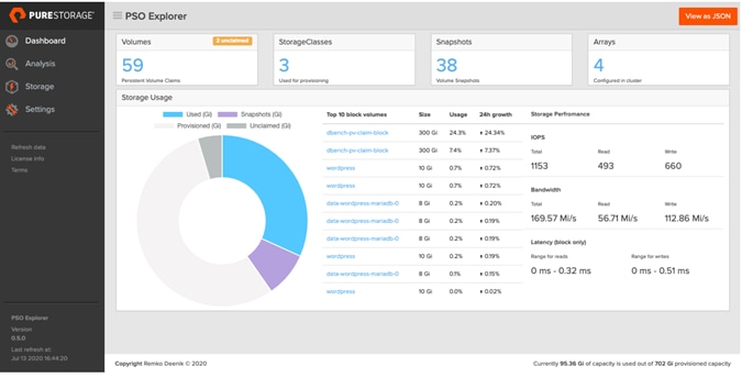
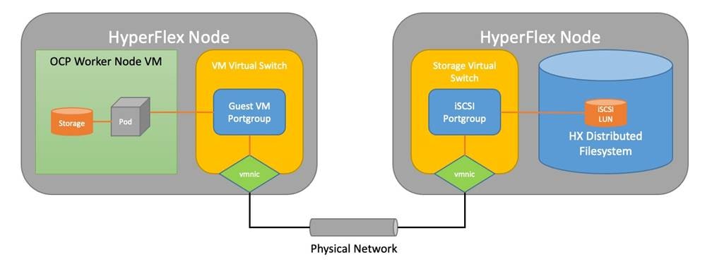
Cisco HyperFlex 4.5 introduced the ability to present internal storage capacity from the Hyperflex distributed filesystem to external servers or VMs via the Internet Small Computer Systems Interface (iSCSI) protocol. Presenting storage via iSCSI differs from the standard storage presentation in HyperFlex, in that HXDP normally stores virtual disk files for VMs on its internal distributed NFS-based filesystem, whereas iSCSI presents raw block-based storage devices to external clients via an IP network. This iSCSI presentation layer is utilized by the OpenShift CSI plugin to dynamically create iSCSI volumes and present them to the nodes, which are then claimed by the pods who mount the volumes for persistent storage.
Traffic originates from the worker nodes hosting the pods, and terminates on the two iSCSI port groups of the Cisco HyperFlex nodes, as documented below. A distinct VLAN is created for iSCSI traffic, and this VLAN can be standalone or be fully routed to allow connection from hosts in different VLANs. For OpenShift, the iSCSI VLAN would typically be routable, as the worker nodes would exist in a different VLAN than the iSCSI endpoints on the Cisco HyperFlex nodes. A single IP address is configured for the entire cluster, then a pool of addresses is defined for the individual hosts. The pool must contain at least one address per converged node, but it can also be made larger to accommodate future expansions of the cluster. The addressing is assigned as part of a configuration wizard to enable iSCSI support, via the HX Connect webpage after the cluster is installed.
Figure 22. HyperFlex CSI Plugin Networking
VLANs and Subnets
For the base HyperFlex system configuration, multiple VLANs need to be carried to the Cisco UCS domain from the upstream LAN, and these VLANs are also defined in the Cisco UCS configuration. The hx-storage-data VLAN must be a separate VLAN ID from the remaining VLANs. Table 5 lists the VLANs created by the HyperFlex installer in Cisco UCS, and their functions.
| VLAN Name |
VLAN ID |
Purpose |
| hx-inband-mgmt |
Customer supplied |
ESXi host management interfaces HX Storage Controller VM management interfaces HX Storage Cluster roaming management interface |
| hx-inband-repl |
Customer supplied |
HX Storage Controller VM Replication interfaces HX Storage Cluster roaming replication interface |
| hx-storage-data |
Customer supplied |
ESXi host storage VMkernel interfaces HX Storage Controller storage network interfaces HX Storage Cluster roaming storage interface |
| hx-inband-iscsi |
Customer supplied |
iSCSI external storage access |
| vm-network |
Customer supplied |
Guest VM network interfaces |
| hx-vmotion |
Customer supplied |
ESXi host vMotion VMkernel interfaces |
![]() A dedicated network or subnet for physical device management is often used in datacenters. In this scenario, the mgmt0 interfaces of the two Fabric Interconnects would be connected to that dedicated network or subnet. This is a valid configuration for HyperFlex installations with the following caveat; wherever the HyperFlex installer is deployed it must have IP connectivity to the subnet of the mgmt0 interfaces of the Fabric Interconnects, and also have IP connectivity to the subnets used by the hx-inband-mgmt VLANs listed above.
A dedicated network or subnet for physical device management is often used in datacenters. In this scenario, the mgmt0 interfaces of the two Fabric Interconnects would be connected to that dedicated network or subnet. This is a valid configuration for HyperFlex installations with the following caveat; wherever the HyperFlex installer is deployed it must have IP connectivity to the subnet of the mgmt0 interfaces of the Fabric Interconnects, and also have IP connectivity to the subnets used by the hx-inband-mgmt VLANs listed above.
Jumbo Frames
All HyperFlex storage traffic traversing the hx-storage-data VLAN and subnet is configured by default to use jumbo frames, or to be precise, all communication is configured to send IP packets with a Maximum Transmission Unit (MTU) size of 9000 bytes. The Cisco HyperFlex installer will configure jumbo frame support on the appropriate interfaces automatically. Jumbo frames could also significantly improve the performance of iSCSI traffic, which would also improve the performance of the Cisco HyperFlex CSI plugin for pods that require persistent storage. However, doing so can drastically increase the complexity of the configuration. Jumbo frame support requires that all interfaces, switches, initiators and endpoints be configured properly to support the larger than standard MTU size. By default, the Red Hat OpenShift worker nodes would not be configured with a dedicated iSCSI interface with jumbo frame support enabled, and the HyperFlex CSI plugin would also not be configured to use jumbo frames. As such, although support for jumbo frames on the Cisco HyperFlex iSCSI network is possible, it is not recommended to attempt to use jumbo frames at this time.
ESXi Host Design
Building upon the Cisco UCS service profiles and policy designs, the following sections detail the design of the elements within the VMware ESXi hypervisors, system requirements, virtual networking, and the configuration of ESXi for the Cisco HyperFlex HX Distributed Data Platform.
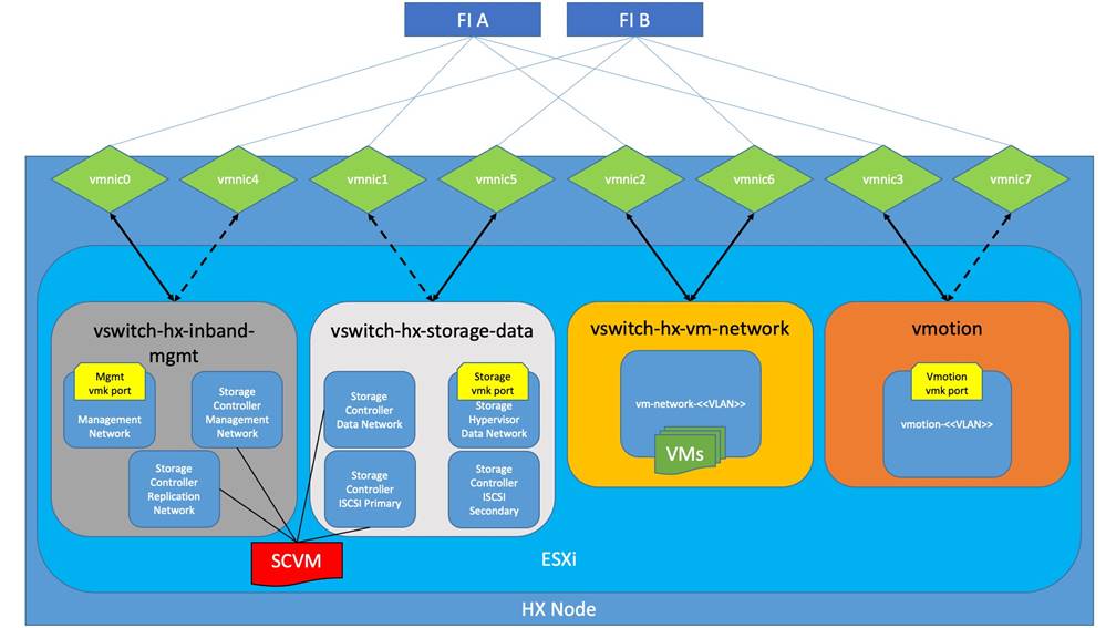
The Cisco HyperFlex system has a pre-defined virtual network design at the ESXi hypervisor level. The ESXi host networking design is derived from the configuration of the nodes as set within Cisco UCS Manager, which is automatically configured via Cisco Intersight during the HyperFlex installation. Four different virtual switches are created by the HyperFlex installer, each using two uplinks, which are each serviced by a vNIC defined in the Cisco UCS service profile. The vSwitches created are:
● vswitch-hx-inband-mgmt: This is the default vSwitch0 which is renamed by the ESXi kickstart file as part of the automated installation. The switch has two uplinks, active on fabric A and standby on fabric B, without jumbo frames. The default VMkernel port, vmk0, is configured in the standard Management Network port group. A second port group is created for the Storage Platform Controller VMs to connect to with their individual management interfaces. A third port group is created for cluster-to-cluster VM snapshot replication traffic. The VLANs are not Native VLANs as assigned to the vNIC templates, and therefore they are defined in ESXi/vSphere.
● vswitch-hx-storage-data: This vSwitch is created as part of the automated installation. The switch has two uplinks, active on fabric B and standby on fabric A, with jumbo frames highly recommended. A VMkernel port, vmk1, is configured in the Storage Hypervisor Data Network port group, which is the interface used for connectivity to the HX Datastores via NFS. A second port group is created for the Storage Platform Controller VMs to connect to with their individual storage interfaces. A third and fourth port groups are created for external iSCSI traffic primary and secondary paths, although only the primary port group is used at this time and is assigned with the hx-inband-iscsi VLAN ID. The VLANs are not Native VLANs as assigned to the vNIC templates, and therefore they are defined in ESXi/vSphere.
● vswitch-hx-vm-network: This vSwitch is created as part of the automated installation. The switch has two uplinks, active on both fabrics A and B, and without jumbo frames. The VLANs are not Native VLANs as assigned to the vNIC templates, and therefore they are defined in ESXi/vSphere.
● vmotion: This vSwitch is created as part of the automated installation. The switch has two uplinks, active on fabric A and standby on fabric B, with jumbo frames highly recommended. The IP addresses of the VMkernel ports (vmk2) are configured during the post_install script execution. The VLAN is not a Native VLAN as assigned to the vNIC templates, and therefore they are defined in ESXi/vSphere.
Table 6 and Figure 23 provide more details about the ESXi virtual networking design as built by the HyperFlex installer by default.
Table 6. Default Virtual Switches
| Virtual Switch |
Port Groups |
Active vmnic(s) |
Passive vmnic(s) |
VLAN IDs |
Jumbo |
| vswitch-hx-inband-mgmt |
Management Network Storage Controller Management Network |
vmnic0 |
vmnic4 |
<<hx-inband-mgmt>> |
no |
| Storage Controller Replication Network |
vmnic0 |
vmnic4 |
<<hx-inband-repl>> |
no |
|
| vswitch-hx-storage-data |
Storage Controller Data Network Storage Hypervisor Data Network |
vmnic5 |
vmnic1 |
<<hx-storage-data>> |
yes |
| Storage Controller ISCSI Primary Storage Controller ISCSI Secondary |
vmnic5 |
vmnic1 |
<<hx-inband-iscsi>> |
yes |
|
| vswitch-hx-vm-network |
vm-network-<<VLAN ID>> |
vmnic2 vmnic6 |
<<vm-network>> |
no |
|
| vmotion |
vmotion-<<VLAN ID>> |
vmnic3 |
vmnic7 |
<<hx-vmotion>> |
yes |
Figure 23. ESXi Default Network Design
Cisco HyperFlex systems are ordered with a factory pre-installation process having been done prior to the hardware delivery. This factory integration work will deliver the HyperFlex servers with the proper firmware revisions pre-set, a copy of the VMware ESXi hypervisor software pre-installed, and some components of the Cisco HyperFlex software already in place. Once on site, the final steps to be performed are reduced and simplified due to the previous factory work. For the purpose of this document, the setup process of Cisco HyperFlex will not be covered, as the instructions are already provided in exiting Cisco online documentation, and Cisco Validated Designs. To access the instructions for Cisco HyperFlex installation, visit the following websites:
Cisco HyperFlex installation guide: https://www.cisco.com/c/en/us/td/docs/hyperconverged_systems/HyperFlex_HX_DataPlatformSoftware/Installation_VMWare_ESXi/4-5/b-hx-install-guide-for-vmware-esxi-4-5.html
Cisco HyperFlex 4.5 Cisco Validated Design: https://www.cisco.com/c/en/us/td/docs/unified_computing/ucs/UCS_CVDs/hx45_vmw_esxi.html
The following sections will guide you through the prerequisites and manual steps needed to install Red Hat OpenShift Container Platform onto an existing Cisco HyperFlex cluster, to install the Cisco HyperFlex CSI plugin, then finally how to perform any remaining post-installation tasks.
Prior to beginning the installation activities, it is important to complete the listed prerequisite installation tasks and gather the following information.
Cisco HyperFlex
The primary requirement before beginning an installation of OpenShift on Cisco HyperFlex is to have completed the installation of the Cisco HyperFlex standard cluster. In addition, the following prerequisites must be met before installation of OpenShift can begin:
● The Cisco HyperFlex cluster must use the VMware ESXi hypervisor and be managed by a VMware vCenter Server.
● The Cisco HyperFlex post_install script should be run in order to configure the cluster with vMotion interfaces, and ensure that guest VM networking is properly configured.
● At least one HyperFlex datastore must be created in order to store virtual machines in the cluster.
● Ensure that Cisco HyperFlex, VMware ESXi, and VMware vCenter are all properly licensed and activated.
Internet Access
Installation of Red Hat OpenShift using the Installer-Provisioned Infrastructure (IPI) method normally requires that the cluster has internet access to download the Red Hat Enterprise Linux CoreOS (RHCOS) images and additional software components which will be used to install the RHOCP cluster. In order to perform the installation, you must have access to the following:
● Access the Red Hat OpenShift Cluster Manager page to download the installation program and perform subscription management. If the cluster has Internet access and you do not disable Telemetry, that service automatically entitles your cluster.
● Access quay.io to obtain the packages that are required to install your cluster.
● Obtain the packages that are required to perform future cluster updates.
Installation on restricted networks where the system does not have internet access is possible by creating internal mirrors of the necessary images and packages. This process splits the installation into two steps; the first creates the install-config.yaml file which is then manually edited with information about the local registry mirror, and the second which completes the installation. Instructions for performing an installation on a restricted network are available here: https://docs.openshift.com/container-platform/4.9/installing/installing_vsphere/installing-restricted-networks-installer-provisioned-vsphere.html
In addition, if internet access is available to the network where the RHOCP cluster will be installed only via a proxy server, then the installation must be performed using the same two step method as described above. The previous link contains detailed instructions for the stanzas which must be manually added to the install-config.yaml file in order to configure the cluster-wide proxy during the initial installation.
Installation Workstation
Installation of the RHOCP cluster is typically done via a Linux workstation by downloading and executing the OpenShift installer program. The installer program is available only for Linux and MacOS. The installation workstation can also be used for administrative purposes by installing the OpenShift command-line tools, which are available for Linux, MacOS and Windows. In order to install the system, the installation workstation must have the vCenter server's root CA certificates installed so they are trusted. In addition, in order to use the installation workstation for administrative purposes, disaster recovery, and installation debugging via accessing the bootstrap VM, you must add an SSH key to the local SSH agent, and specify the key during the installation process. Instructions for these tasks are provided below.
Red Hat Account
A valid account is required to log in to the Red Hat OpenShift Cluster Manager page, in order to create the cluster and create the pull secret. The pull secret is created in the cluster manager webpage and downloaded, then the pull secret is supplied during the installation program. Afterwards, the cluster is listed in the Red Hat Hybrid Cloud Console, where its version and status can be viewed.
IP Addressing
Static IP addresses for the Cisco HyperFlex system are allocated from the appropriate subnets and VLANs during the installation of the Cisco HyperFlex cluster. For installation of the Cisco HyperFlex CSI plugin, the iSCSI network must be configured on the Cisco HyperFlex cluster as a post-installation step. Networking for iSCSI requires a pool with one static IP address per Cisco HyperFlex converged node, plus one additional roaming IP address for the cluster. For example, a 4 node Cisco HyperFlex cluster would require 5 static IP addresses in the subnet designated for iSCSI traffic associated with the <<hx-inband-iscsi>> VLAN.
In addition, two static IP addresses are required for initial external access to the newly installed OpenShift cluster. One IP is a load balanced address for the cluster API, and the second is for a wildcard DNS record for application access. Finally, the IP addresses of Cisco UCS Manager, which manages the Cisco HyperFlex cluster, and the IP address of the Cisco HyperFlex HX Connect webpage must be known and recorded.
Record the additional static IP addresses required in Table 7.
Table 7. Static IP Address Information
| Item |
Value |
| iSCSI cluster IP address |
|
| iSCSI node pool IP addresses |
|
| OpenShift API address |
|
| OpenShift app wildcard address |
|
| Cisco UCS Manager |
|
| Cisco HyperFlex HX Connect |
|
Table 8. Example Static IP Address Information
| Item |
Value |
| iSCSI cluster IP address |
192.168.110.20 |
| iSCSI node pool IP addresses |
192.168.110.21 - 192.168.110.24 |
| OpenShift API address |
192.168.100.99 |
| OpenShift app wildcard address |
192.168.100.100 |
| Cisco UCS Manager |
10.29.133.106 |
| Cisco HyperFlex HX Connect |
10.29.133.208 |
By default, installation of RHOCP using the Installer-Provisioned Infrastructure (IPI) method uses DHCP to assign IP addresses to the master and worker nodes. Due to this, a working DHCP server must be available with a valid and active scope for the subnet the nodes will be placed in. The DHCP server must be configured with scope options to assign clients with a gateway address, at least one DNS server address, the DNS domain name, and at least one valid NTP server address. After the cluster installation has completed, and anytime additional nodes are brought online, the DHCP leases must be converted to reservations, so that the nodes will continue to use the same IP addresses if they are rebooted.
Table 9 provides an example of the DHCP server and scope information used in the testing for this document:
| Item |
Value |
| DHCP Server IP address |
192.168.100.6 |
| DHCP Scope Pool Range |
192.168.100.101 - 192.168.103.254 |
| DHCP Scope Subnet Mask |
255.255.252.0 |
| DHCP Scope Router (003) |
192.168.100.1 |
| DNS Server (006) |
10.29.133.110 |
| DNS Domain Name (015) |
hx.lab.cisco.com |
| NTP Server (042) |
10.29.133.101, 10.29.133.102 |
DNS domains and A records must be created to support the installation of the OpenShift cluster. Within the base DNS domain, a child domain for the new cluster must be created, and within that, one A record must be created pointing to the static IP address for API access as recorder earlier. Within the RHOCP child domain, a second child domain named "apps" must be created, and within that, one wildcard A record must be created pointing to the wildcard IP address as recorded earlier. For example, if the base domain is hx.lab.cisco.com, and the cluster domain will be named ocp49, the child domain of ocp49.hx.lab.cisco.com must be created. Within the ocp49.hx.lab.cisco.com domain, another child domain named apps must be created. Two A records would be required, the first would be api.ocp49.hx.lab.cisco.com, pointing to the load balanced API IP address. The second A record would be a wildcard record, *.apps.ocp49.hx.lab.cisco.com, pointing to the wildcard application IP address.
Using the following tables, gather the required DNS information for the installation, by listing the information required, and an example configuration.
Table 10. DNS Server Records
| Item |
Value |
| DNS base domain |
|
| DNS RHOCP cluster domain |
|
| API A Record (api.<ocp_domain>.<base_domain>) |
|
| App Wildcard A Record (*.apps.<ocp_domain>.<base_domain>) |
|
Table 11. Example DNS Server Records
| Item |
Value |
| DNS base domain |
hx.lab.cisco.com |
| DNS RHOCP domain |
ocp49 |
| API A Record (api.<ocp_domain>.<base_domain>) |
192.168.100.99 api.ocp49.hx.lab.cisco.com |
| App Wildcard A Record (*.apps.<ocp_domain>.<base_domain>) |
192.168.100.100 *.apps.ocp49.hx.lab.cisco.com |
Consistent time clock synchronization is required across the components of the HyperFlex system and for OpenShift Container Platform, provided by reliable NTP servers. The use of public NTP servers is highly discouraged, instead a reliable internal NTP server should be used.
Using the following tables, gather the required NTP information for the installation by listing the information required, and an example configuration.
Table 12. NTP Server Information
| Item |
Value |
| NTP Server #1 |
|
| NTP Server #2 |
|
| Timezone |
|
Table 13. NTP Server Example Information
| Item |
Value |
| NTP Server #1 |
ntp1.hx.lab.cisco.com (10.29.133.101) |
| NTP Server #2 |
ntp2.hx.lab.cisco.com (10.29.133.102) |
| Timezone |
(UTC-8:00) Pacific Time |
At a minimum, there are 4 VLANs that need to be trunked to the Cisco UCS Fabric Interconnects that comprise the HyperFlex system; a VLAN for the HyperFlex and ESXi Management group, a VLAN for the HyperFlex Storage group, a VLAN for the VMotion group, and at least one VLAN for the guest VM traffic. The creation of those VLANs is handled via the Cisco HyperFlex installer. The guest VMs which will run the OpenShift cluster will operate on one of the guest VM VLANs.
To support the installation of the Cisco HyperFlex CSI plugin, an additional VLAN for iSCSI traffic must be created and configured within Cisco UCS Manager. If this VLAN is separate from the VLAN that the OpenShift VMs run in, then traffic between these two VLANs must be routable between them.
Using the following tables, gather the required VLAN information for the installation by listing the information required, and an example configuration.
| Name |
ID |
| <<hx-vm-data>> |
|
| <<hx-inband-iscsi>> |
|
Table 15. VLAN Example Information
| Name |
ID |
| vm-network-100 |
100 |
| iscsi-110 |
110 |
Several usernames and passwords need to be defined or known as part of the OpenShift on HyperFlex installation process. Using the following table, gather the required username and password information.
Table 16. Usernames and Passwords
| Account |
Username |
Password |
| UCS Manager Administrator |
admin |
<<ucsm_admin_pw>> |
| HyperFlex Administrator |
admin |
<<hx_admin_pw>> |
| vCenter Administrator |
<<vcenter_administrator>> |
<<vcenter_admin_pw>> |
Cisco HyperFlex Boost Mode
An optional configuration, referred to as HyperFlex Boost Mode, can be manually configured to give additional vCPU resources to the Cisco HyperFlex storage controller VMs. Boost mode can show performance increases for applications which are extremely sensitive to storage latency, meanwhile the physical servers have CPU resources to spare. If the Cisco HyperFlex cluster running Red Hat OpenShift will run pods that need persistent storage, and those pods are sensitive to storage latency, then enabling Boost Mode can significantly improve their performance. Boost mode is only available on standard clusters running all-flash and all-NVMe nodes, and the physical CPUs installed must have at least the requisite number of physical cores available. Table 17 lists the CPU resource reservation of the storage controller VMs:
Table 17. Controller VM CPU Reservations
| Server Models |
Number of vCPU |
Shares |
Reservation |
Limit |
| All-Flash models |
8 |
Low |
10800 MHz |
unlimited |
| All-Flash Boost Mode |
12 |
Low |
10800 MHz |
unlimited |
| All-NVMe models |
12 |
Low |
10800 MHz |
unlimited |
| All-NVMe Boost Mode |
16 |
Low |
10800 MHz |
unlimited |
Enabling Boost Mode requires that each of the HX controller VMs, or the entire node is powered off one-by-one, and could be disruptive to workloads in the cluster if proper care is not taken. Due to this, it is recommended that if Boost Mode is desired for the workloads running in the RHOCP cluster, it should be enabled at the earliest possible time, ideally before the RHOCP installation is performed. For detailed instructions on how to enable Boost Mode, refer to the following white paper:
Workstation Preparation
In order to perform installation debugging or disaster recovery on your cluster, you must provide an SSH key to both your ssh-agent and specify the key during the OpenShift installation program. This key is used to access the bootstrap machine to troubleshoot installation issues and is also used to SSH into the master and worker nodes as the user named core for various post-installation activities. If you have already created an SSH key pair then it may be used, as long as the public key is stored in the ~/.ssh directory. If you do not have an SSH key, create a key by following these steps:
1. From the command line of the installation workstation, create a new key by entering the following command, specifying the path and filename, such as ~/.ssh/id_rsa
# ssh-keygen -t rsa -N '' -f <path>/<file_name>
2. Start the SSH agent as a background task:
# eval "$(ssh-agent -s)"
3. Add the newly created key to the SSH agent:
# ssh-add <path>/<file_name>
The installation workstation must trust the vCenter server's root CA certificates for the installation to be successful. The root CA certificates of the vCenter server must be downloaded from the vCenter server and added to the system trust of the workstation before the installation process can begin. To trust the vCenter root CA certificates, follow these steps:
1. Using a web browser, open the base URL of the vCenter server which will manage the new OpenShift cluster to be installed. Note, this is the base page, not the HTML5 vSphere client page, nor the vCenter management page on port 5480.
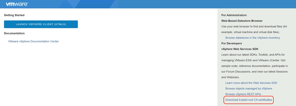
2. Click the Download trusted root CA certificates link and save the zip file named download.zip.
3. Copy the file to the installation workstation using SCP into a known location, such as the home folder for the root user.
4. As an alternative, the certificates file can be downloaded from vCenter via the CLI, directly to the management workstation. Use the following command as an example:
# wget --no-proxy https://vcenter.hx.lab.cisco.com/certs/download.zip --no-check-certificate
5. From the command line of the workstation, extract the download.zip file:
# unzip download.zip
6. Examine the contents of the extracted zip file. A folder named certs will have been extracted, and inside that folder is a folder named lin, which contains the certificate files.
7. Copy the certificate files to the system trust by running the following command:
# cp certs/lin/* /etc/pki/ca-trust/source/anchors
8. Update the system trust by running the following command:
# update-ca-trust extract
Install OpenShift Installer and Tools
The final preparation steps are the download and installation of the OpenShift install program, and the OpenShift client tools on the workstation. Downloading the installer and tools from the Red Hat OpenShift Cluster Manager webpage will always provide the latest version of both tools. If a specific earlier version of the installer and tools are required, they may be downloaded from the public OpenShift mirror site here: https://mirror.openshift.com/pub/openshift-v4/clients/ocp/
In our example, we install using the most current version of RHOCP 4.9, which as of the time of this document was 4.9.15, available here: https://mirror.openshift.com/pub/openshift-v4/clients/ocp/4.9.15/
The OpenShift install program is named openshift-install-linux-4.9.15.tar.gz, and the client is named openshift-client-linux-4.9.15.tar.gz.
To install the OpenShift install program and the OpenShift client, follow these steps:
1. From the command line of the workstation, create a folder for the installation of this OpenShift cluster, for example openshift:
# mkdir openshift
2. Change directory to the openshift folder, then download the install program and client tools, using the following commands as examples:
# wget https://mirror.openshift.com/pub/openshift-v4/clients/ocp/4.9.15/openshift-install-linux-4.9.15.tar.gz
# wget https://mirror.openshift.com/pub/openshift-v4/clients/ocp/4.9.15/openshift-client-linux-4.9.15.tar.gz
3. Extract the contents of the two files by running the following commands as examples:
# tar -xvf openshift-install-linux-4.9.15.tar.gz
# tar -xvf openshift-client-linux-4.9.15.tar.gz
4. Move the executable files named oc and kubectl to a location in your Linux PATH, for example:
# mv oc kubectl /usr/local/bin/
5. Verify the versions of the OpenShift install and client program are the desired versions before proceeding:
# oc version
Client Version: 4.9.15
# ./openshift-install version
./openshift-install 4.9.15
built from commit eb132dae953888e736c382f1176c799c0e1aa49e
release image quay.io/openshift-release-dev/ocp-release@sha256:bb1987fb718f81fb30bec4e0e1cd5772945269b77006576b02546cf84c77498e
release architecture amd64
OpenShift Installation
Installation of OpenShift involves running the command line OpenShift install program, which asks a series of questions and for information about the cluster being installed. Once all the information is gathered, the install program will deploy a bootstrap VM in the vSphere cluster running on Cisco HyperFlex, and from that bootstrap VM it will create 3 master VMs. The master VMs will initialize the etcd database and cluster API, then when those items are confirmed to be online it will create the first 3 worker VMs.
Pull Secret
A pull secret must be created and downloaded prior to starting the OpenShift install program. The pull secret will be supplied to the install program when prompted. To create and download the pull secret, follow these steps:
1. Using a web browser, log in to the Red Hat OpenShift Cluster Manager webpage.
2. Click Clusters on the left-hand menu, then click the Create Cluster button.
3. Click on the Datacenter tab, then scroll down to click on vSphere.
4. Click the Installer-Provisioned Infrastructure button.
5. Click the button to download the pull secret as a text file. You may also click the link to copy the pull secret to the clipboard so it can be pasted into the OpenShift install program in the following steps.
OpenShift Install
Installation of Red Hat OpenShift Container Platform is done using the command line installer program which was downloaded earlier. To install the OpenShift cluster, follow these steps:
1. From the command line of the installation workstation, change to the directory with the installation program, for example, openshift.
2. Execute the OpenShift installation program, creating a folder for the cluster to be installed, using the following command as an example:
# ./openshift-install create cluster --dir=ocp49 --log-level=info
3. Use the arrow keys to select the SSH key to use for this installation, then press Enter.
4. Use the arrow keys to select vSphere as the platform, then press Enter.
5. Enter the URL of the vCenter server which will manage this cluster, then press Enter.
6. Enter the username of an account with administrative privileges in vCenter, then press Enter.
7. Enter the password of the vCenter administrative account, then press Enter.
8. Use the arrow keys to select the HX datastore to store the RHOCP VMs in, then press Enter.
9. Use the arrow key to select the guest VM portgroup where the RHOCP guest VMs will connect to the network, then press Enter.
10. Enter the virtual IP address for access to the RHOCP API, as created earlier, then press Enter.
11. Enter the virtual IP address for incoming application access, as created earlier, then press Enter.
12. Enter the base DNS domain where the cluster will be installed, then press Enter.
13. Enter the cluster name, then press Enter.
14. Paste the pull secret, then press Enter.
15. Observe via the command line as the components are downloaded, the VMs are created, and the cluster comes online.
# ./openshift-install create cluster --dir=ocp49 --log-level=info
? SSH Public Key /root/.ssh/id_rsa.pub
? Platform vsphere
? vCenter vcenter.hx.lab.cisco.com
? Username administrator@vsphere.local
? Password [? for help] ********
INFO Connecting to vCenter vcenter.hx.lab.cisco.com
INFO Defaulting to only available datacenter: Datacenter
INFO Defaulting to only available cluster: M5-Hybrid
? Default Datastore DS1
? Network vm-network-100
? Virtual IP Address for API 192.168.100.99
? Virtual IP Address for Ingress 192.168.100.100
? Base Domain hx.lab.cisco.com
? Cluster Name ocp49
? Pull Secret [? for help] ***************************************************************************
INFO Obtaining RHCOS image file from 'https://rhcos-redirector.apps.art.xq1c.p1.openshiftapps.com/art/storage/releases/rhcos-4.9/49.84.202110081407-0/x86_64/rhcos-49.84.202110081407-0-vmware.x86_64.ova?sha256='
INFO Creating infrastructure resources...
INFO Waiting up to 20m0s for the Kubernetes API at https://api.ocp49.hx.lab.cisco.com:6443...
INFO API v1.22.3+e790d7f up
INFO Waiting up to 30m0s for bootstrapping to complete...
INFO Destroying the bootstrap resources...
INFO Waiting up to 40m0s for the cluster at https://api.ocp49.hx.lab.cisco.com:6443 to initialize...
INFO Waiting up to 10m0s for the openshift-console route to be created...
INFO Install complete!
INFO To access the cluster as the system:admin user when using 'oc', run 'export KUBECONFIG=/root/openshift/ocp49/auth/kubeconfig'
INFO Access the OpenShift web-console here: https://console-openshift-console.apps.ocp49.hx.lab.cisco.com
INFO Login to the console with user: "kubeadmin", and password: "*****-*****-*****-*****"
INFO Time elapsed: 25m47s
16. Copy and store the password for the kubeadmin account as this is the only time it will be shown, and it is required in order to log in to the OpenShift management console webpage.
After the initial cluster installation has completed, several tests should be performed and recommended settings applied to the new cluster.
Initial Access and Testing
Test access to the new cluster using the command line tools and the web console. To establish access via the command line, execute the following commands from the workstation:
# export KUBECONFIG=/root/openshift/ocp49/auth/kubeconfig
# oc whoami
# oc get nodes -o wide
The output should show all 6 of the master and worker nodes, their IP addresses, and the expected software versions running in the cluster.
Open a web browser and navigate to the OpenShift management console webpage as shown when the installation completed, named https://console-openshift-console.apps.<RHOCP_domain>.<base_domain>, for example: https://console-openshift-console.apps.ocp49.hx.lab.cisco.com
Log into the OpenShift management console with the username kubeadmin, and the password shown in the command line when the installation completed. Verify you have access using this account and the supplied password.
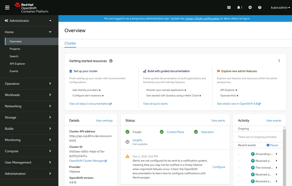
Additional Worker Nodes
Adding more of the default worker nodes only requires the default machine set to be scaled to a higher number. Use the following commands as an example of how to scale the number of worker nodes from 3 to 4:
# oc get machinesets -n openshift-machine-api
NAME DESIRED CURRENT READY AVAILABLE AGE
ocp49-stjht-worker 3 3 3 3 50m
# oc scale --replicas=4 machineset ocp49-stjht-worker -n openshift-machine-api
machineset.machine.openshift.io/ocp49-stjht-worker scaled
Change Worker Node Resource Allocation
By default, worker node VMs are deployed with 2 CPU and 8GB RAM each. If this configuration is insufficient for your pods' compute resource needs, then a new machine set must be created which deploys worker nodes with a larger number of resources. The new machine set can be created and scaled, which will deploy the new worker nodes, then the original machine set can be scaled down to zero. The existing machine set details can be viewed by running the following example command:
# oc get machineset ocp49-stjht-worker -n openshift-machine-api -o yaml
Using the information from the default machine set YAML data, a new machine set YAML file can be created, wherein the name, labels, replicas and resource values can be modified as desired. An example YAML file is provided below, which creates a new machine set with 8 CPU and 16GB RAM per worker.
apiVersion: machine.openshift.io/v1beta1
kind: MachineSet
metadata:
labels:
machine.openshift.io/cluster-api-cluster: ocp49-stjht
name: ocp49-stjht-worker-8c-16g
namespace: openshift-machine-api
spec:
replicas: 1
selector:
matchLabels:
machine.openshift.io/cluster-api-cluster: ocp49-stjht
machine.openshift.io/cluster-api-machine-role: worker
machine.openshift.io/cluster-api-machine-type: worker
machine.openshift.io/cluster-api-machineset: ocp49-stjht-worker-8c-16g
template:
metadata:
labels:
machine.openshift.io/cluster-api-cluster: ocp49-stjht
machine.openshift.io/cluster-api-machine-role: worker
machine.openshift.io/cluster-api-machine-type: worker
machine.openshift.io/cluster-api-machineset: ocp49-stjht-worker-8c-16g
spec:
metadata: {}
providerSpec:
value:
apiVersion: vsphereprovider.openshift.io/v1beta1
credentialsSecret:
name: vsphere-cloud-credentials
diskGiB: 120
kind: VSphereMachineProviderSpec
memoryMiB: 16384
metadata:
creationTimestamp: null
network:
devices:
- networkName: vm-network-100
numCPUs: 8
numCoresPerSocket: 1
snapshot: ""
template: ocp49-stjht-rhcos
userDataSecret:
name: worker-user-data
workspace:
datacenter: Datacenter
datastore: DS1
folder: /Datacenter/vm/ocp49-stjht
resourcePool: /Datacenter/host/M5-Hybrid/Resources
server: vcenter.hx.lab.cisco.com
status:
replicas: 0
To create new worker nodes with a larger resource allocation per node, follow these steps:
1. From the management workstation, create a machine set YAML file, using the preceding example as a guide. For example, create a file named machineset-8c-16g.yaml.
2. Apply the new machine set by running the following command:
# oc apply -f machineset-8c-16g.yaml
3. Observe in vCenter, the OpenShift management console, and/or the command line to verify the new worker node(s) are created with the specification you defined.
# oc get nodes -o wide
4. Scale the number of the new worker nodes by modifying the machine set, if the number of desired replicas was not set in the initial YAML file.
# oc scale --replicas=4 machineset ocp49-stjht-worker-8c-16g -n openshift-machine-api
5. After you have verified the new worker nodes are online, the safest way to move all existing pods to the new worker nodes is to cordon and drain the existing worker nodes one-by-one, until they are all empty and blocked from scheduling any new pods on them. Use the following command examples to cordon and drain the original worker nodes:
# oc get nodes
# oc adm cordon <worker-node>
# oc adm drain <worker node name> --ignore-daemonsets --delete-emptydir-data --force=true
6. After the new larger worker nodes are online, reduce the number of the original worker nodes by modifying the number of replicas in the original machine set, one-by-one, until the machine set is reduced to zero replicas. Use the following command examples to scale the original worker nodes down to zero:
# oc scale --replicas=3 machineset ocp49-stjht-worker -n openshift-machine-api
# oc scale --replicas=2 machineset ocp49-stjht-worker -n openshift-machine-api
# oc scale --replicas=1 machineset ocp49-stjht-worker -n openshift-machine-api
# oc scale --replicas=0 machineset ocp49-stjht-worker -n openshift-machine-api
7. Lastly, if the original machine set is no longer needed, it may be deleted:
# oc delete machineset ocp49-stjht-worker -n openshift-machine-api
As an alternative, the existing default machine set can be modified in place by running the command:
# oc edit machineset <machineset_name> -n openshift-machine-api
Edit the values for disk size, if desired, memory, CPUs and cores per socket, then save the changes. After editing the default machine set, the worker nodes can be deleted one-by-one, which will cause them to be recreated using the modified values in the default machine set:
# oc delete machine <machine_name> -n openshift-machine-api
Infrastructure Nodes
For production environments, it is recommended to create additional infrastructure nodes on which to run several of the built-in cluster services, as opposed to running them on the worker nodes. This arrangement provides separation between the pods running your applications and services, from the services that run the OpenShift cluster itself. For example, the OpenShift router pods, the registry, monitoring pods such as Prometheus, Grafana and AlertManger, plus the logging pods such as Elastcisearch and Kibana can all be moved to the infrastructure nodes. Creating infra nodes is similar to creating worker nodes via machine sets, however the infra nodes are labeled with the infra label, and then pods can be directed to run only on nodes with that label via a node selector. An example YAML file is provided below, which will create a machine set for infra nodes with 3 replicas, each already labeled with the infra label.
apiVersion: machine.openshift.io/v1beta1
kind: MachineSet
metadata:
labels:
machine.openshift.io/cluster-api-cluster: ocp49-stjht
name: ocp49-stjht-infra
namespace: openshift-machine-api
spec:
replicas: 3
selector:
matchLabels:
machine.openshift.io/cluster-api-cluster: ocp49-stjht
machine.openshift.io/cluster-api-machine-role: infra
machine.openshift.io/cluster-api-machine-type: infra
machine.openshift.io/cluster-api-machineset: ocp49-stjht-infra
template:
metadata:
labels:
machine.openshift.io/cluster-api-cluster: ocp49-stjht
machine.openshift.io/cluster-api-machine-role: infra
machine.openshift.io/cluster-api-machine-type: infra
machine.openshift.io/cluster-api-machineset: ocp49-stjht-infra
spec:
metadata:
labels:
node-role.kubernetes.io/infra: ""
providerSpec:
value:
apiVersion: vsphereprovider.openshift.io/v1beta1
credentialsSecret:
name: vsphere-cloud-credentials
diskGiB: 120
kind: VSphereMachineProviderSpec
memoryMiB: 16384
metadata:
creationTimestamp: null
network:
devices:
- networkName: vm-network-100
numCPUs: 8
numCoresPerSocket: 1
snapshot: ""
template: ocp49-stjht-rhcos
userDataSecret:
name: worker-user-data
workspace:
datacenter: Datacenter
datastore: DS1
folder: /Datacenter/vm/ocp49-stjht
resourcePool: /Datacenter/host/M5-Hybrid/Resources
server: vcenter.hx.lab.cisco.com
status:
replicas: 0
To create new infra nodes, follow these steps:
1. From the management workstation, create a machine set YAML file, using the preceding example as a guide. For example, create a file named machineset-infra.yaml.
2. Apply the new machine set by running the following command:
# oc apply -f machineset-infra.yaml
3. Observe in vCenter, the OpenShift management console, and/or the command line to verify the new infra node(s) are created with the specification you defined.
# oc get nodes
The three new infra nodes will be labeled as infra, although their roles will be both infra and worker, therefore user pods can be scheduled on the new infra nodes. Any node which runs user pods requires an active subscription with Red Hat. In order to dedicate these new nodes to only the infra role and prevent user pods from running on them, a MachineConfig must be created, which generates a MachineConfigPool for only the infra nodes. An example YAML file is provided below, which creates the MachineConfig for nodes with the infra label.
apiVersion: machineconfiguration.openshift.io/v1
kind: MachineConfigPool
metadata:
name: infra
spec:
machineConfigSelector:
matchExpressions:
- {key: machineconfiguration.openshift.io/role, operator: In, values: [worker,infra]}
nodeSelector:
matchLabels:
node-role.kubernetes.io/infra: ""
To create new infra MachineConfig, follow these steps:
1. From the management workstation, create a MachineConfig YAML file, using the preceding example as a guide. For example, create a file named machineconfig-infra.yaml.
2. Create the new MachineConfig by running the following command:
# oc apply -f machineconfig-infra.yaml
3. Verify via the command line the new MachineConfig exists by running the command below. You should see a MachineConfig with a name beginning with rendered-infra-* prefix
# oc get machineconfig
4. Verify the MachineConfigPool is available by running the command below. You should see output similar to the provided example.
# oc get mcp
NAME CONFIG UPDATED UPDATING DEGRADED MACHINECOUNT READYMACHINECOUNT UPDATEDMACHINECOUNT DEGRADEDMACHINECOUNT AGE
infra rendered-infra-c93cfc2601634bfd264b0d1fddc89b55 True False False 3 3 3 0 4m39s
master rendered-master-8de6794fea4c731070f5d6adff1d4a2b True False False 3 3 3 0 4h46m
worker rendered-worker-c93cfc2601634bfd264b0d1fddc89b55 True False False 4 4 4 0 4h46m
Move the Router
In the default configuration, the router pods are configured to run on worker nodes. To move the router, follow these steps:
1. Move the router pods to the infra nodes by editing the ingresscontroller resource:
# oc edit ingresscontroller default -n openshift-ingress-operator
2. Edit the resource by adding the nodeSelector stanza to the spec section:
spec:
nodePlacement:
nodeSelector:
matchLabels:
node-role.kubernetes.io/infra: ""
3. View the router pods and note they should be terminating and restarting on the infra nodes:
# oc get pod -n openshift-ingress -o wide
Move Monitoring Pods
Moving the monitoring pods is done by creating a ConfigMap and applying it to the cluster. An example of the ConfigMap file is provided below:
apiVersion: v1
kind: ConfigMap
metadata:
name: cluster-monitoring-config
namespace: openshift-monitoring
data:
config.yaml: |+
alertmanagerMain:
nodeSelector:
node-role.kubernetes.io/infra: ""
prometheusK8s:
nodeSelector:
node-role.kubernetes.io/infra: ""
prometheusOperator:
nodeSelector:
node-role.kubernetes.io/infra: ""
grafana:
nodeSelector:
node-role.kubernetes.io/infra: ""
k8sPrometheusAdapter:
nodeSelector:
node-role.kubernetes.io/infra: ""
kubeStateMetrics:
nodeSelector:
node-role.kubernetes.io/infra: ""
telemeterClient:
nodeSelector:
node-role.kubernetes.io/infra: ""
openshiftStateMetrics:
nodeSelector:
node-role.kubernetes.io/infra: ""
thanosQuerier:
nodeSelector:
node-role.kubernetes.io/infra: ""
To move the monitoring components to the infra nodes, follow these steps:
1. From the management workstation, create a ConfigMap YAML file, using the preceding example as a guide. For example, create a file named cluster-monitoring-configmap.yaml.
2. Create the new ConfigMap by running the following command:
# oc create -f cluster-monitoring-configmap.yaml
3. Verify via the command line the monitoring pods move to the infra nodes by running the command below. You should see a machine config with a name beginning with rendered-infra-* prefix
# watch 'oc get pod -n openshift-monitoring -o wide'
Move Logging
OpenShift cluster logging resources can be moved by applying a NodeSelector, similar to how the router pods were moved in the preceding example. These resources are not installed in an RHOCP cluster by default; therefore they only need to be modified if they had been manually installed, otherwise their configuration can be set with the appropriate NodeSelector when they are installed.
DHCP Reservations
Once the overall RHOCP cluster configuration is set with the number of master nodes, worker nodes and infra nodes required, it is important to configure your DHCP server to supply all of the RHOCP VMs with the same IP addresses each time they boot. Converting the existing DHCP leases into reservations is the most effective way to achieve this requirement. The process of converting the existing leases into reservations is different depending on which software or hardware appliance is used to provide the DHCP service, and therefore this document will not provide instructions on how to create these reservations.
![]() For simplicity's sake, the RHOCP cluster installation described and tested uses a fixed node configuration, and therefore benefits from having fixed IP addresses via DHCP reservations. This document does not describe configurations using the cluster autoscaler, which can dynamically create and destroy worker nodes as workloads demand.
For simplicity's sake, the RHOCP cluster installation described and tested uses a fixed node configuration, and therefore benefits from having fixed IP addresses via DHCP reservations. This document does not describe configurations using the cluster autoscaler, which can dynamically create and destroy worker nodes as workloads demand.
VMware Settings
Due to the nature of deploying a clustered system such as RHOCP, on top of a clustered infrastructure, such as Cisco HyperFlex, multiple VMs of the same type could in fact run on the same physical node within the Cisco HyperFlex cluster. While rare, this does expose the possibility of all of the master nodes, or infra nodes going offline if a single HX-series node should fail. In order to mitigate this risk, it is recommended that anti-affinity rules are created in vCenter, in order to keep more than one RHOCP VM of each role from running alongside each other on the same physical hardware nodes. To create the anti-affinity rules, follow these steps:
1. Using a web browser, log in using an account with administrative rights, to the vCenter vSphere Client page for the vCenter server managing the Cisco HyperFlex cluster, which is running the RHOCP cluster.
2. From the Hosts and Clusters view, click on the vSphere cluster object which represents the Cisco HyperFlex cluster.
3. Click on the Configure tab, click on VM/Host Rules, then click Add.
4. Enter a name for the first group, such as "RHOCP Masters", set the type as Separate Virtual Machines, then click Add.
5. Select the three RHOCP master VMs from the list, then click OK.
6. Click OK to complete the rule.
7. Repeat steps 3-6 for the remaining node roles, such as infra and worker, in order to force vCenter to spread those VMs across all the available Cisco HyperFlex nodes. In many systems there may be more worker node VMs than there are Cisco HyperFlex nodes, in those cases an anti-affinity rule may not be required.
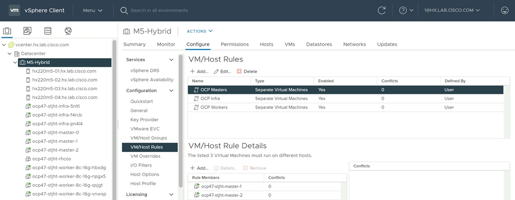
The Cisco HyperFlex CSI plugin enables the dynamic provisioning and attachment of iSCSI-based storage to user pods which require persistent storage. While many user pods run microservices which function as intermediaries between other systems, and require no persistent storage, some workloads have the requirement to store data permanently in a storage device that appears local to the pod. While storage could be provisioned and mounted from a network location in the datacenter, this requires manual steps to configure the pods to do so, and is difficult to automate. Using the CSI plugin framework of Kubernetes, storage providers can write integration plugins which can be accessed by the underlying Kubernetes API, in order to automatically provision storage for pods which need them, and dynamically attach the provisioned storage on demand.
Several pods are deployed as part of the solution, all of which are managed by the HXCSI Driver, which is in turn deployed and configured by the HXCSI Operator. Three StatefulSets are deployed; the csi-provisioner, csi-attacher, and csi-resizer, all of which play their own role in storage presentation. Once registered in the cluster, the RHOCP API contacts the CSI pods to perform the necessary tasks when user pods require persistent storage. The provisioner pods create and provision the datastores and storage volumes on the Cisco HyperFlex system. The attacher pods attach user pods to the provisioned storage when the pods are created, started or scaled up. The resizer pods handle resizing operations when requested. Finally, a DaemonSet is deployed, running a csi-nodeplugin pod on each worker node, which facilitates communication with kubelet on each worker node where the user pods will run.
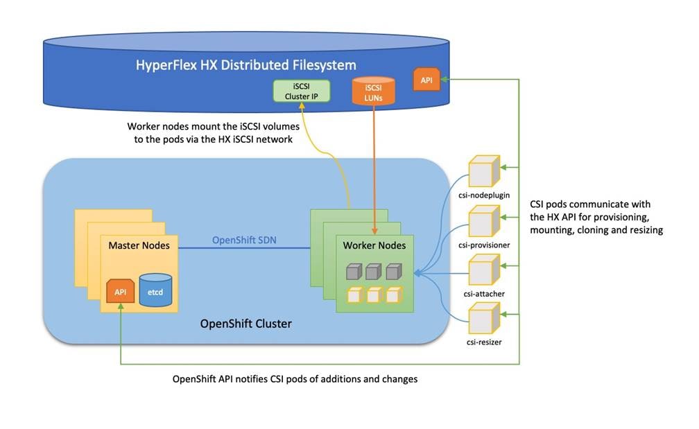
Prior to the installation of the Cisco HyperFlex CSI plugin, the following prerequisites must be met and completed.
Configure Cisco HyperFlex iSCSI Network
The first step before installing the Cisco HyperFlex CSI plugin is to configure the iSCSI network of the HyperFlex cluster where the persistent volumes will be accessed. The traffic will ingress/egress via the port groups named “Storage Controller ISCSI Primary” and “Storage Controller ISCSI Secondary”, which are part of the virtual switch named “vswitch-hx-storage-data”. Although there are two port groups, only the primary port group is used at this time. A clustered IP address is set, and a pool of addresses is created to assign to the individual nodes. The pool can be made larger than the number of nodes in order to accommodate future growth. A VLAN ID is assigned to the port groups for the iSCSI traffic, and it is recommended to use a dedicated VLAN for iSCSI in order to keep it separated from the standard internal HXDP storage traffic which is using the same vNICs. If the VLAN does not exist in the Cisco UCS configuration it will be created, and the VLAN ID will be assigned to the “storage-data” vNIC templates. Configuration of iSCSI networking is done via the Cisco HyperFlex HX Connect management webpage.
To configure the iSCSI networking settings, follow these steps:
1. Using a web browser, navigate to the IP address of the Cisco HyperFlex HX Connect page, and log in using the admin credentials.
2. In the HyperFlex Connect webpage, click on iSCSI then click the link for Configure Network.
3. Enter the subnet used for iSCSI traffic in CIDR notation. If the subnet is routable, check the box next to Gateway, and enter the default gateway IP address.
4. Enter the starting and ending addresses for the IP address range that will be assigned to the nodes, then click Add IP Range.
5. Enter the iSCSI Storage IP which will be assigned to the cluster.
6. Leave the check box to set a non-default, such as jumbo MTU, unchecked.
7. Choose the option to Create a New VLAN, then enter the VLAN ID, VLAN name, plus the UCS Manager IP address, admin username, and password. Alternatively, choose the option to use an existing VLAN if desired, and enter the VLAN ID.
8. Click Configure.
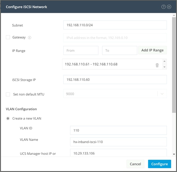
9. A job will be started to configure the iSCSI networking settings. Monitor the status of the job until it completes.
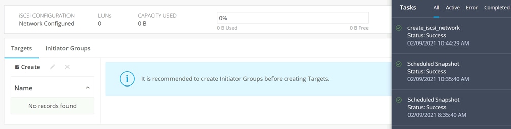
![]() Normally, when initiators connect from a subnet outside of the one configured for iSCSI on the HyperFlex cluster, for example if the iSCSI subnet is routable and a client connects from a different subnet, then an entry must be made into the iSCSI allow list before connections will succeed. The Cisco HyperFlex CSI plugin will automatically manage these firewall entries; therefore no manual configuration is required.
Normally, when initiators connect from a subnet outside of the one configured for iSCSI on the HyperFlex cluster, for example if the iSCSI subnet is routable and a client connects from a different subnet, then an entry must be made into the iSCSI allow list before connections will succeed. The Cisco HyperFlex CSI plugin will automatically manage these firewall entries; therefore no manual configuration is required.
![]() Using an existing VLAN ID would require manual steps in Cisco UCS Manager to add the VLAN to the two "storage-data" vNIC templates. If they were not already added, creation of the iSCSI network would fail due to the missing VLAN ID in the vNIC templates.
Using an existing VLAN ID would require manual steps in Cisco UCS Manager to add the VLAN to the two "storage-data" vNIC templates. If they were not already added, creation of the iSCSI network would fail due to the missing VLAN ID in the vNIC templates.
Verify iSCSI Enabled on RHOCP Worker Nodes
In order for the Cisco HyperFlex CSI plugin to function properly, the iSCSI daemon must be enabled and running on the RHOCP worker nodes. In our testing, we have observed that the iSCSI daemon may not be enabled and running by default on newly installed worker nodes. Therefore, it is important to log on to the worker nodes and ensure that the iSCSI daemon is fully enabled and running prior to any attempt to use the Cisco HyperFlex CSI plugin, as the plugin will fail to deploy and user pods using persistent volumes will fail to deploy if the daemon is not running. Verifying the status of the daemon requires logging in to the worker nodes from the management workstation which was used to install the RHOCP cluster, as it has completed the proper certificate exchange in order to log in to the worker nodes as the user named "core". To verify the status of the iSCSI daemon on the worker nodes, follow these steps:
1. From the command line of the management workstation, find the IP addresses of the worker nodes by running the following command:
# oc get nodes -o wide
2. Observe the IP addresses of the worker nodes and use them in the following command to log on to the first worker node as the user named "core":
# ssh core@<worker_node_ip>
3. Enter "yes" if prompted to continue connecting and to store the fingerprint in the known_hosts file.
4. Enter the following command to view the status of the iSCSI service (daemon), the example shows a newly installed worker node where the service is inactive:
# sudo systemctl status iscsid
● iscsid.service - Open-iSCSI
Loaded: loaded (/usr/lib/systemd/system/iscsid.service; disabled; vendor preset: disabled)
Active: inactive (dead) since Tue 2021-11-02 21:19:27 UTC; 28min ago
Docs: man:iscsid(8)
man:iscsiuio(8)
man:iscsiadm(8)
Main PID: 658 (code=exited, status=0/SUCCESS)
Status: "Ready to process requests"
Nov 02 21:19:26 localhost iscsid[658]: iscsid: can't open InitiatorName configuration file /etc/iscsi/initiatorname.iscsi
Nov 02 21:19:26 localhost iscsid[658]: iscsid: Warning: InitiatorName file /etc/iscsi/initiatorname.iscsi does not exist or does not contain a properly formatted InitiatorName. If using software iscsi (isc>
Nov 02 21:19:26 localhost iscsid[658]: Example: InitiatorName=iqn.2001-04.com.redhat:fc6.
Nov 02 21:19:26 localhost iscsid[658]: If using hardware iscsi like qla4xxx this message can be ignored.
Nov 02 21:19:26 localhost iscsid[658]: iscsid: can't open InitiatorAlias configuration file /etc/iscsi/initiatorname.iscsi
Nov 02 21:19:26 localhost systemd[1]: Started Open-iSCSI.
Nov 02 21:19:27 localhost iscsid[658]: iscsid: iscsid shutting down.
Nov 02 21:19:27 localhost systemd[1]: Stopping Open-iSCSI...
Nov 02 21:19:27 localhost systemd[1]: iscsid.service: Succeeded.
Nov 02 21:19:27 localhost systemd[1]: Stopped Open-iSCSI.Enable
5. Enable the iSCSI service by issuing the following command:
# sudo systemctl enable iscsid
6. Restart the iSCSI service by issuing the following command:
# sudo systemctl restart iscsid
7. View the status of the iSCSI service after enabling and restarting the service:
# sudo systemctl status iscsid
● iscsid.service - Open-iSCSI
Loaded: loaded (/usr/lib/systemd/system/iscsid.service; enabled; vendor preset: disabled)
Active: active (running) since Tue 2021-11-02 21:49:55 UTC; 33s ago
Docs: man:iscsid(8)
man:iscsiuio(8)
man:iscsiadm(8)
Main PID: 53151 (iscsid)
Status: "Ready to process requests"
Tasks: 1 (limit: 50360)
Memory: 3.2M
CPU: 6ms
CGroup: /system.slice/iscsid.service
└─53151 /usr/sbin/iscsid -f
Nov 02 21:49:55 ocp49-9mh9h-worker-x98r4 systemd[1]: Starting Open-iSCSI...
Nov 02 21:49:55 ocp49-9mh9h-worker-x98r4 systemd[1]: Started Open-iSCSI.
8. Repeat steps 2-7 for each remaining RHOCP worker node, until all worker nodes have their iSCSI daemons enabled and running.
Installation
Installation of the Cisco HyperFlex CSI plugin begins with the installation of the HXCSI operator via the Red Hat OpenShift Container Platform OperatorHub. After the operator is installed, an access token for the Cisco HyperFlex cluster API must be generated, so that the RHOCP cluster can communicate with the HyperFlex cluster using the HX API. Once the token is obtained, the HXCSI driver can be installed, which deploys the CSI plugin pods to the worker nodes, enabling other user pods to be configured with persistent volumes.
Install HXCSI Driver Operator
The Cisco HyperFlex CSI plugin is distributed for Red Hat OpenShift Container Platform as a downloadable file from cisco.com, and also as an installable operator from the RHOCP OperatorHub. An Operator is a method of packaging, deploying and managing a Kubernetes-native application, which essentially functions as a custom controller. A controller is a core concept within Kubernetes which continuously compares, and if necessary, reconciles the desired state and the current state of an object. Objects are well known resources like Pods, Services, ConfigMaps, or PersistentVolumes. Operators apply this model at the level of entire applications, thereby functioning as application-specific controllers. To install the Cisco HyperFlex CSI operator, follow these steps:
1. Using a web browser, log in to the OpenShift management console with the username kubeadmin, and the password shown in the command line when the installation completed.
2. From the left-hand navigation menu, select Operators, then click OperatorHub.
3. Click HXCSI Driver on the left or enter "HXCSI" in the filter field to locate the Cisco HyperFlex CSI Operator, then click the Operator to select it.
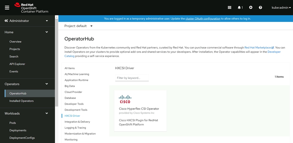
4. Click Install.
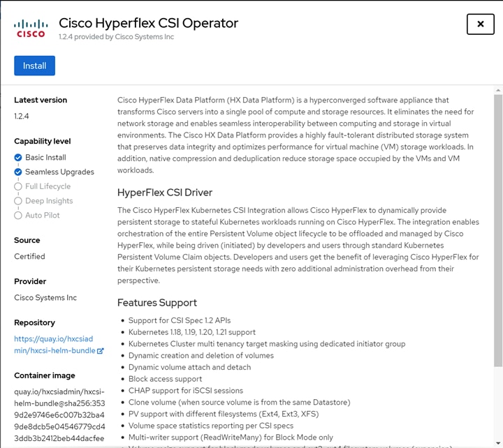
5. Leave all the options as their defaults in the next screen, then click Install.
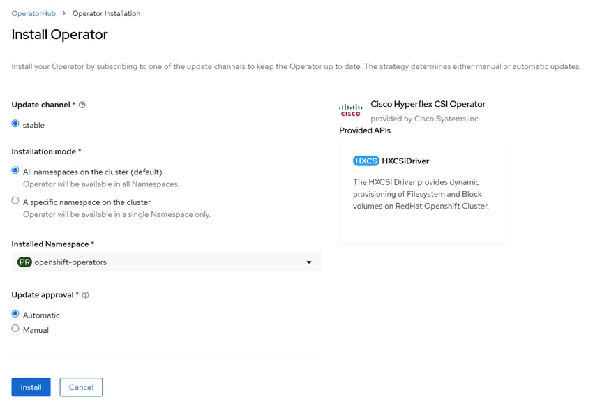
6. Observe the operator installation process until it completes, then click View Operator.
API Token
Because the CSI plugin must communicate with the Cisco HyperFlex API to create and present the iSCSI volumes to the containers, an API token must be generated and supplied to the plugin for it to function. The token must be generated prior to installing and configuring the HXCSI driver, which is managed by the Operator. To generate the HyperFlex API token, follow these steps:
1. From the management workstation, log on to the first worker node as the user named "core":
# ssh core@<worker_node_ip>
2. Enter the following command, substituting a unique name for the clientId field, and using the HyperFlex cluster management IP address for the mgmtvip field:
# podman run -it quay.io/hxcsiadmin/servicetoken:latest -clientId myClient123 -mgmtvip 10.29.133.208 -username admin
3. When prompted, enter the admin account password for the HyperFlex cluster.
4. Copy the output of the line beginning with ServiceToken:, this is the raw token for use in the following steps.
Trying to pull quay.io/hxcsiadmin/servicetoken:latest...
Getting image source signatures
Copying blob 9ed91f07ec88 done
Copying blob 8ee8f3c07d77 done
Copying blob 06ba635a9aee done
Copying config 0e09bdbe62 done
Writing manifest to image destination
Storing signatures
password for [admin] at [10.29.133.208]:
ServiceToken: ey****************.*****************
An alternative method for acquiring the API involves downloading the most recent Cisco HyperFlex CSI plugin and executing a program via the command line. If for any reason the previous method fails, you can use the following method to generate the API token:
1. Download the Cisco HyperFlex CSI plugin from cisco.com.
2. Copy the file to a known location on the management workstation via SCP or any other available method.
3. Log on to the management workstation via the CLI and change directory to the location where the CSI plugin .tar.gz file was copied to.
4. Expand the CSI plugin file using the following command as an example:
# tar -xvf hxcsi-1.2.1a-601.tar.gz
5. Change directory to the setup folder which was just created.
# cd setup
6. Execute the hxcsi-setup program, specifying a unique clientId value for this access token, the IP address of the HX iSCSI cluster interface, and the HX cluster's management interface. Use the following command as a reference:
# ./hxcsi-setup -cluster-name M5-Hybrid -clientId myClient123 -hx-csi-image quay.io/hxcsiadmin -iscsi-url 192.168.110.20 -url 10.29.133.208 -username admin
7. Enter the password for the Cisco HyperFlex admin account when prompted and press Enter.
8. Change directories to the hxcsi-deploy folder created by the hxcsi-setup program.
# cd hxcsi-deploy
9. View the contents of the hxcsi-config.yaml file by entering the following command:
# cat hxcsi-config.yaml
10. Locate the line the begins with token: and copy the contents to the clipboard.
11. Echo the clipboard contents and pipe it to base64 in order to convert the token to a raw key in the following format: echo "<token>" | base64 -d
# echo "ZXlKaGJHY2lPaUpJVXpJMU5pSjkuZXlKemRXSWlPaUoxYzJWeWN5OWhaRzFwYmlJc0luVnpaWElpT2lKaFpHMXBiaUlzSW1Oc2FXVnVkR2xrSWpvaWJYbERiR2xsYm5ReE1qTWlMQ0pwYzNOMVpXUkJkQ0k2TVRZek5UazNNek0yTnpnM09Dd2lkRzlyWlc1TWFXWmxWR2x0WlNJNkxURXNJbWg1Y0dWeWRtbHpiM0lpT2lKRmMzZ2lmUS5NcmYyekJuQW15MlgyNWFnVnRja1A2NU9fam1aZzlOVnprVkl6TDdMRDJZ" | base64 -d
12. The output of the previous command is the raw token. Copy the raw token to another file or location, and also document the clientId which was used during the hxcsi-setup program, as they will both be needed in the next section.
Install the HXCSI Driver
After the HXCSI Operator is installed and the HX API access token is retrieved, installation of the HXCSI driver can begin. Installation of the driver creates all of the CSI pods across the RHOCP cluster to enable the CSI functions, allowing user pods to request persistent volumes and have then automatically provisioned and attached to the pods. To install the HXCSI driver, follow these steps:
1. Log into the OpenShift Management Console webpage.
2. From the left-hand navigation menu, select Operators, then click Installed Operators.
3. At the top of the screen, it is important that the Project dropdown menu is clicked, and select the default project. Failure to select the default project could lead to deployment failures due to security constraints.
4. Click the Cisco HyperFlex CSI Operator.

5. From the Details page, click the link for Create Instance underneath the HXCSIDriver.
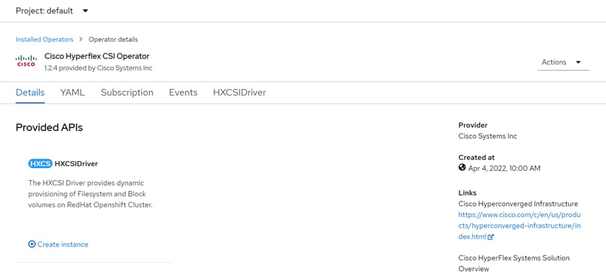
6. Fill-in the values underneath Driver Inputs, following the recommendations below:
a. clientId: This must match the clientId value used when retrieving the HX API token.
b. dockerRegistryName: Enter the public or private registry containing the HXCSI container images, for example: quay.io/hxcsiadmin.
c. iscsiUrl: Enter the IP address of the HX cluster's iSCSI interface. This is the roaming/clustered interface, not one of the individual nodes' iSCSI interfaces.
d. token: Enter the raw token from the base64 command as retrieved in the previous section.
e. url: Enter the IP address of the HX cluster's roaming/clustered management interface.
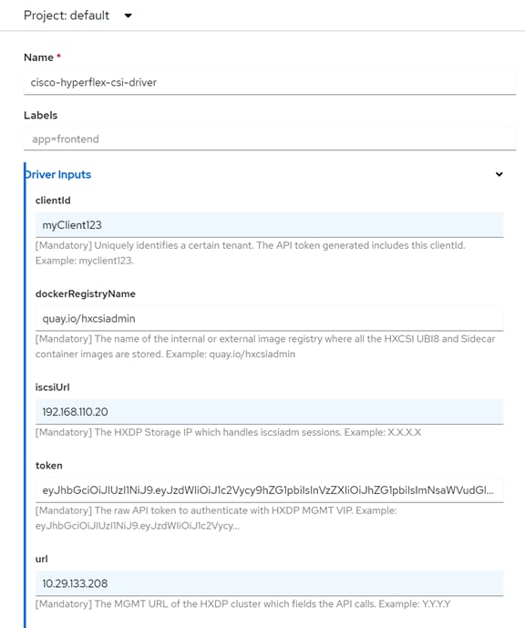
7. Click Create.
8. Observe the status of the cisco-hyperflex-csi-driver until the status shows "Conditions: Initialized, Deployed."
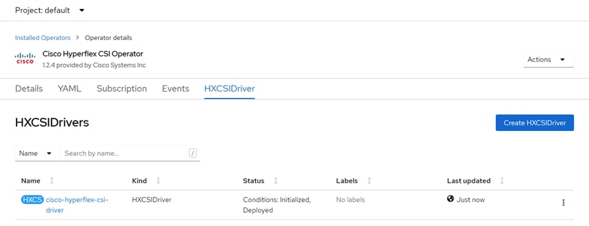
9. From the left-hand navigation menu, select Workloads, then click StatefulSets.
![]() Observe that the three csi-* StatefulSets have 2 of 2 pods deployed.
Observe that the three csi-* StatefulSets have 2 of 2 pods deployed.
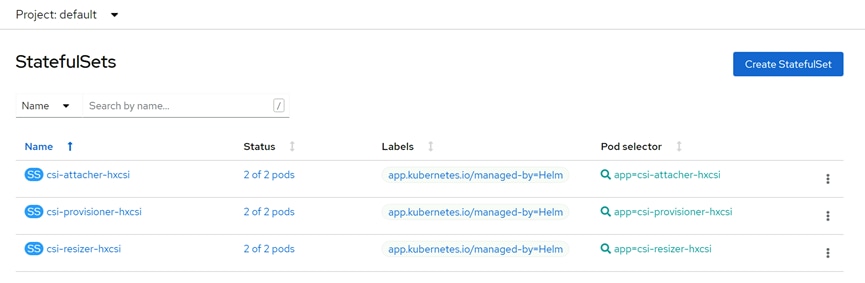
10. From the left-hand navigation menu, select Workloads, then click DaemonSets.
11. Observe that the csi-nodeplugin-hxcsi DeamonSet has 3 of 3 pods deployed.
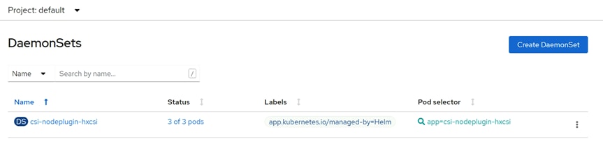
Test
After the installation of the HXCSIDriver, a storage class can be created in the RHOCP cluster using the provisioner named csi-hxcsi. In general, a single storage class is created and from that storage class many persistent volume claims can be made. When created, persistent volume claims cause the RHOCP API to contact the provisioner pods, who create the persistent volumes on the HX cluster, via the storage class and provider. The attacher pods of the HX CSI plugin are contacted by the RHOCP API for new volume attachment requests from the user pods and attaches the pods to the dynamically created volumes. While these can be created individually using the OpenShift Management Console GUI, in reality, the persistent volume claims and the user pods which require them can be created simultaneously via the command line for new workloads being deployed.
Each persistent volume claim (pvc) results in a newly provisioned iSCSI volume on the HX datastore. In this way, each pvc is analogous to a storage device. The storage devices can be created as raw block devices, or as filesystem devices with ext3, etx4 or xfs formatting already applied. Filesystem devices make it easy to mount an already formatted device to the user pod's local filesystem. Raw block devices are often chosen for shared devices such as a clustered OS or database quorum device. Storage devices can be cloned if necessary, and also expanded to larger capacities.
Create StorageClass
In most environments, only a single StorageClass is needed in order to provision persistent volumes from the Cisco Hyperflex Distributed Filesystem. The StorageClass links to the csi-hxcsi provisioner, and also defines the filesystem format (by default ext4), the name and size of the underlying datastore within the Cisco HyperFlex cluster. This datastore is separate from the standard NFS based HX datastores used to store virtual machines. It is also separate from iSCSI datastores supporting external iSCSI attachments from external systems, and is used only for iSCSI volumes supporting Kubernetes based workloads. The StorageClass can be created in the OpenShift Management Console webpage or via the command line. In both cases it is recommended to use the YAML file to specify all of the available options. An example YAML file is provided below. To create the Cisco HX StorageClass, follow these steps:
GUI
1. Log into the OpenShift Management Console webpage.
2. From the left-hand navigation menu, select Storage, then click StorageClasses.
3. Click Create StorageClass, then click Edit YAML.
4. Modify the YAML file in place, or paste in the values created in a separate editor, then click Create.
CLI
1. Log into the management workstation via the command line.
2. Create the StorageClass YAML file and edit its contents, using the example below. For example, create a file named hxcsi-storageclass.yaml.
3. Apply the configuration of the storage class by entering the command below:
# oc apply -f hxcsi-storageclass.yaml
Example YAML File
kind: StorageClass
apiVersion: storage.k8s.io/v1
metadata:
name: csi-hxcsi-default
provisioner: csi-hxcsi
allowVolumeExpansion: true
parameters:
datastore: default-ds
datastoreSize: "1000000000000"
![]() The StorageClass name, the datastore name, and the datastoreSize can be modified as needed.
The StorageClass name, the datastore name, and the datastoreSize can be modified as needed.
Create Persistent Volume Claims and Deployments
Persistent Volume Claims specify a volume to be created and attached to a pod. The claim specifies the size of the volume, the type of volume, either filesystem or block, and if the volume is read/write accessible by only one pod or many pods at one time. Deployments can then be created, which create user pods that attach to and consume the PVCs. The user pods must specify the PVC they will consume, along with either their filesystem mount point or a device tree location for a raw device. The persistent volume claims and deployments can be created in the OpenShift Management Console webpage or via the command line. Using the GUI, the PVCs must be created separately from the deployments that consume them. Via the command line, a PVC and deployment can be created in a single step. In both cases it is recommended to use the YAML file to specify all of the available options. Example YAML files are provided below. To create the persistent volume claims and deployments, follow these steps:
GUI
1. Log into the OpenShift Management Console webpage.
2. From the left-hand navigation menu, select Storage, then click PersistentVolumeClaims.
3. Click Create PersistentVolumeClaim, then click Edit YAML.
4. Modify the YAML file in place, or paste in the values created in a separate editor, then click Create.
5. From the left-hand navigation menu, select Workloads, then click Deployments.
6. Paste in the YAML file contents for the deployment, then click Create.
CLI
1. Log into the management workstation via the command line.
2. Create the deployment YAML file and edit its contents, using the examples below. For example, create a file named hxcsi-nginx.yaml, which creates the PVC and the deployment in one step.
3. Apply the configuration of the storage class by entering the command below:
# oc apply -f hxcsi-nginx.yaml
Example YAML Files
kind: PersistentVolumeClaim
apiVersion: v1
metadata:
name: hxpvclaim-nginx
spec:
accessModes:
- ReadWriteOnce
resources:
requests:
storage: 5Gi
storageClassName: csi-hxcsi-default
apiVersion: apps/v1
kind: Deployment
metadata:
name: test
labels:
app: test
spec:
replicas: 1
selector:
matchLabels:
app: test
template:
metadata:
labels:
app: test
spec:
volumes:
- name: test-volume
persistentVolumeClaim:
claimName: hxpvclaim-nginx
containers:
- name: nginx
image: nginx:1.7.9
ports:
- containerPort: 80
volumeMounts:
- mountPath: "/usr/mnt/test"
name: test-volume
kind: PersistentVolumeClaim
apiVersion: v1
metadata:
name: hxpvclaim-nginx
spec:
accessModes:
- ReadWriteOnce
resources:
requests:
storage: 5Gi
storageClassName: csi-hxcsi-default
---
apiVersion: apps/v1
kind: Deployment
metadata:
name: test
labels:
app: test
spec:
replicas: 1
selector:
matchLabels:
app: test
template:
metadata:
labels:
app: test
spec:
volumes:
- name: test-volume
persistentVolumeClaim:
claimName: hxpvclaim-nginx
containers:
- name: nginx
image: nginx:1.7.9
ports:
- containerPort: 80
volumeMounts:
- mountPath: "/usr/mnt/test"
name: test-volume
The K8s iSCSI datastore is visible from within the HX Connect management webpage, after clicking the Kubernetes menu.
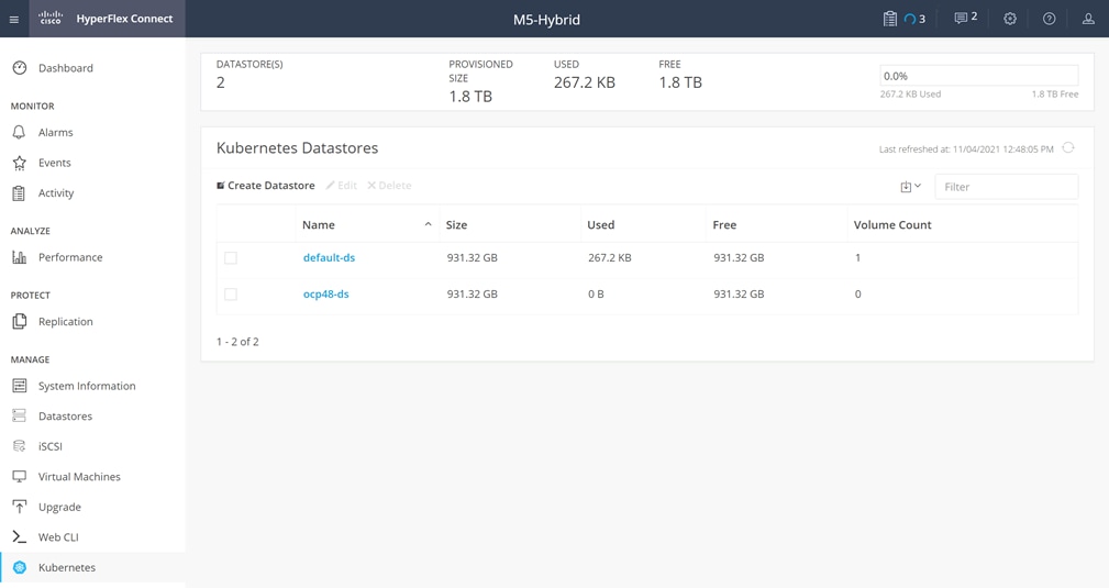
![]() Kubernetes datastores are not managed in the same manner as iSCSI or HX datastores. While the datastores and pvcs are visible, they are intended to be dynamically created and mounted from the RHOCP environment. Kubernetes datastores cannot be deleted via the GUI, even when all the contained pvcs are deleted.
Kubernetes datastores are not managed in the same manner as iSCSI or HX datastores. While the datastores and pvcs are visible, they are intended to be dynamically created and mounted from the RHOCP environment. Kubernetes datastores cannot be deleted via the GUI, even when all the contained pvcs are deleted.
Configure Different Filesystem Formats
By default, filesystem PVCs are formatted with the ext4 filesystem. Both the ext3 and xfs filesystem formats are available, although these options are set in the StorageClass. Therefore, if there is a requirement to use more than one filesystem format, then there must be a unique StorageClass defined for each. As a result, there would also be multiple K8s datastores seen in the Cisco HyperFlex system, each with a different filesystem format. Example YAML files are provided below. To create the Cisco HX StorageClass using either ext3 or xfs formatting, follow these steps:
GUI
1. Log into the OpenShift Management Console webpage.
2. From the left-hand navigation menu, select Storage, then click StorageClasses.
3. Click Create StorageClass, then click Edit YAML.
4. Modify the YAML file in place, or paste in the values created in a separate editor, then click Create.
CLI
1. Log into the management workstation via the command line.
2. Create the StorageClass YAML file and edit its contents, using the examples below. For instance, create a file named hxcsi-storageclass-xfs.yaml.
3. Apply the configuration of the storage class by entering the command below:
# oc apply -f hxcsi-storageclass-xfs.yaml
Example YAML Files
kind: StorageClass
apiVersion: storage.k8s.io/v1
metadata:
name: csi-hxcsi-xfs
provisioner: csi-hxcsi
allowVolumeExpansion: true
parameters:
datastore: ds-xfs
datastoreSize: "1000000000000"
fsType: xfs
kind: StorageClass
apiVersion: storage.k8s.io/v1
metadata:
name: csi-hxcsi-ext3
provisioner: csi-hxcsi
allowVolumeExpansion: true
parameters:
datastore: ds-ext3
datastoreSize: "1000000000000"
fsType: ext3
Configure Block Mode Devices
Configuring block mode devices instead of filesystem devices is done in the configuration of the PVC. Concurrently, setting the read/write access mode is also part of the PVC. Three access modes are available; ReadWriteOnce, ReadWriteMany and ReadOnlyMany. ReadWriteOnce is appropriate for single containers, while ReadWriteMany is only supported for block mode devices, and can be used for multiple containers which require access to a single storage device, such as a shared data volume or a cluster quorum disk. When using ReadWriteMany access mode on a block device, the user pods are responsible for file system locking or reservations, in order to prevent simultaneous writes to the same location resulting in filesystem inconsistency or corruption. ReadOnlyMany mode allows multiple user pods to read the data in the volume but not modify it. Example YAML files are provided below. To create the persistent volume claims using block mode and/or multiple pods, follow these steps:
GUI
1. Log into the OpenShift Management Console webpage.
2. From the left-hand navigation menu, select Storage, then click PersistentVolumeClaims.
3. Click Create PersistentVolumeClaim, then click Edit YAML.
4. Modify the YAML file in place, or paste in the values created in a separate editor, then click Create.
5. From the left-hand navigation menu, select Workloads, then click Deployments.
6. Paste in the YAML file contents for the deployment, then click Create.
CLI
1. Log into the management workstation via the command line.
2. Create the deployment YAML file and edit its contents, using the examples below. For example, create a file named hxcsi-nginx.yaml, which creates the PVC and the deployment in one step.
3. Apply the configuration of the storage class by entering the command below:
# oc apply -f hxcsi-nginx.yaml
Example YAML Files
kind: PersistentVolumeClaim
apiVersion: v1
metadata:
name: hxpvclaim-block-rwm
spec:
accessModes:
- ReadWriteMany
volumeMode: Block
resources:
requests:
storage: 20Gi
storageClassName: csi-hxcsi-default
apiVersion: apps/v1
kind: Deployment
metadata:
name: test-block
labels:
app: test-block
spec:
replicas: 1
selector:
matchLabels:
app: test-block
template:
metadata:
labels:
app: test-block
spec:
volumes:
- name: test-block-volume
persistentVolumeClaim:
claimName: hxpvclaim-block-rwm
containers:
- name: nginx
image: dockerhub.cisco.com/docker.io/nginx:1.7.9
volumeDevices:
- name: test-block-volume
devicePath: /dev/xvda
ports:
- containerPort: 80
Clone a Persistent Volume
Cloning an existing persistent volume is done by creating a new persistent volume claim using specific option in the YAML file. The new PVC can then be used by a new deployment, and the pods in that deployment will start with an exact copy of the volume from the original PVC. The clone must be at least the same size or larger than the original volume. Example YAML files are provided below. To create the persistent volume claims as a clone of an existing PVC, follow these steps:
GUI
1. Log into the OpenShift Management Console webpage.
2. From the left-hand navigation menu, select Storage, then click PersistentVolumeClaims.
3. Click Create PersistentVolumeClaim, then click Edit YAML.
4. Modify the YAML file in place, or paste in the values created in a separate editor, then click Create.
CLI
1. Log into the management workstation via the command line.
2. Create the PVC and deployment YAML file and edit its contents, using the examples below. For example, create a file named hxcsi-nginx-pvc-clone.yaml, which creates the PVC clone and the deployment in one step.
3. Apply the configuration of the storage class by entering the command below:
# oc apply -f hxcsi-nginx-pvc-clone.yaml
Example YAML Files
kind: PersistentVolumeClaim
apiVersion: v1
metadata:
name: hxpvclaim-nginx-clone
spec:
storageClassName: csi-hxcsi-default
accessModes:
- ReadWriteOnce
resources:
requests:
storage: 5Gi
dataSource:
kind: PersistentVolumeClaim
name: hxpvclaim-nginx
apiGroup: ""
kind: PersistentVolumeClaim
apiVersion: v1
metadata:
name: hxpvclaim-nginx-clone
spec:
storageClassName: csi-hxcsi-default
accessModes:
- ReadWriteOnce
resources:
requests:
storage: 5Gi
dataSource:
kind: PersistentVolumeClaim
name: hxpvclaim-nginx
apiGroup: ""
---
apiVersion: apps/v1
kind: Deployment
metadata:
name: testclone-csi
labels:
app: testclone-csi
spec:
replicas: 1
selector:
matchLabels:
app: testclone-csi
template:
metadata:
labels:
app: testclone-csi
spec:
volumes:
- name: testclone-volume
persistentVolumeClaim:
claimName: hxpvclaim-nginx-clone
containers:
- name: nginx
image: nginx:1.7.9
ports:
- containerPort: 80
volumeMounts:
- mountPath: "/usr/mnt/testclone"
name: testclone-volume
Expand a Persistent Volume
Expanding a persistent volume is done via an expansion task on the persistent volume claim. This task is most easily done via the RHOCP Management Console webpage. To expand a volume, follow these steps:
1. Log into the OpenShift Management Console webpage.
2. From the left-hand navigation menu, select Storage, then click PersistentVolumeClaims.
3. Click the persistent volume claim you wish to expand.
4. From the Actions dropdown menu, click Expand PVC.
5. Enter the new size of the PVC, then click Expand.
The expansion task can take a couple of minutes to complete, when done the GUI will refresh to display the new size of the persistent volume.
By default, OpenShift Container Platform does not have any storage available during the initial installation. Therefore, to prevent errors and allow the initial installation to complete, the image registry operator is started in an unmanaged state. Once the initial installation is completed, storage can be configured, allowing the image registry to be managed, and started. Several options are available for image registries for Red Hat OpenShift. In many environments, an external registry may already be configured in the environment and therefore the RHOCP registry will not need to be configured at all. For production environments where image registry redundancy is needed, the most common method to provide a shared storage volume to the RHOCP image registry pods is via an NFS server, because NFS will properly handle the file locking for the multiple registry pods.
The image registry operator can be configured to use a PVC, which points to the NFS share from the NFS server, allowing the registry pods to start. The NFS server could be an actual server external to the RHOCP cluster, a storage array providing NFS shares, or it could be a user pod within the RHOCP cluster itself providing the NFS share. The user pod acting as an NFS server could use a PVC for its storage volume, and that PVC could be provisioned from the Cisco HyperFlex cluster after the HXCSI plugin has been configured. Due to the range of configuration possibilities, configuration of the image registry is beyond the scope of this paper, however it is valuable as an example of how the Cisco HyperFlex CSI plugin can be used to provide persistent storage for a use case like an NFS server.
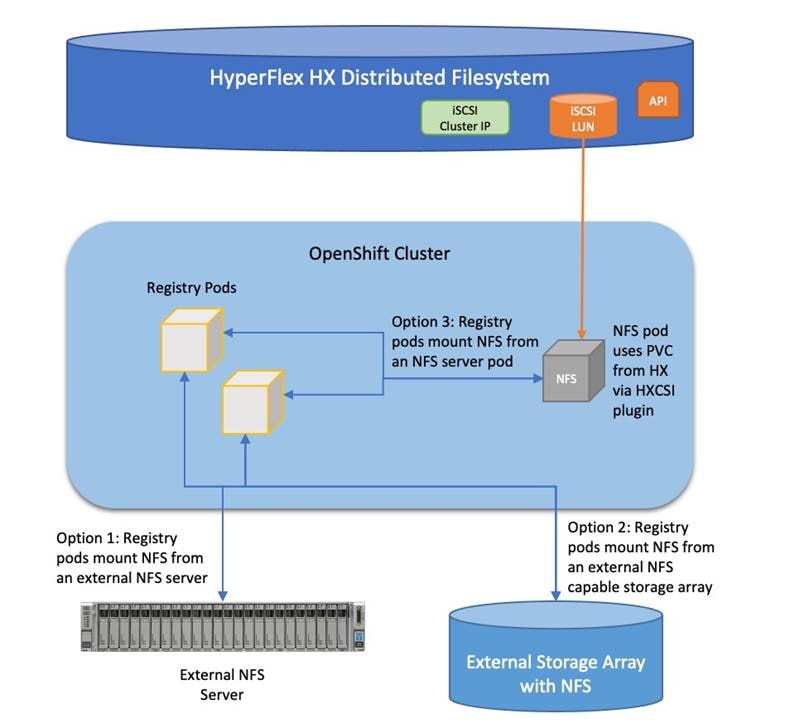
Brian Everitt, Technical Marketing Engineer, Computing Systems Product Group, Cisco Systems, Inc.
Brian is an IT industry veteran with over 24 years of experience deploying server, network, and storage infrastructures for companies around the world. During his tenure at Cisco, he has been a lead Advanced Services Solutions Architect for Microsoft solutions, virtualization, and SAP Hana on Cisco UCS. Currently his role covers solutions development for Cisco’s HyperFlex Hyperconverged Infrastructure product line, focusing on performance evaluation and product quality. Brian has earned multiple certifications from Microsoft, Cisco, and VMware.
The author wishes to acknowledge the following individual for their significant assistance and technical guidance as part of the testing and creation of this document, and the overall solution:
● Naveen Sreeramachandra, Software Engineering Technical Leader, Computing Systems Product Group, Cisco Systems, Inc.
For comments and suggestions about this guide and related guides, join the discussion on Cisco Community at https://cs.co/en-cvds.