FlexPod Datacenter for Citrix Virtual Apps and Desktops with VMware vSphere 8 for up to 2500 Sessions
Available Languages
Bias-Free Language
The documentation set for this product strives to use bias-free language. For the purposes of this documentation set, bias-free is defined as language that does not imply discrimination based on age, disability, gender, racial identity, ethnic identity, sexual orientation, socioeconomic status, and intersectionality. Exceptions may be present in the documentation due to language that is hardcoded in the user interfaces of the product software, language used based on RFP documentation, or language that is used by a referenced third-party product. Learn more about how Cisco is using Inclusive Language.
- US/Canada 800-553-2447
- Worldwide Support Phone Numbers
- All Tools
 Feedback
 Feedback

In partnership with:

About the Cisco Validated Design Program
The Cisco Validated Design (CVD) program consists of systems and solutions designed, tested, and documented to facilitate faster, more reliable, and more predictable customer deployments. For more information, go to: http://www.cisco.com/go/designzone.
Cisco Validated Designs (CVD) consist of systems and solutions that are designed, tested, and documented to facilitate and improve customer deployments. These designs incorporate a wide range of technologies and products into a portfolio of solutions that have been developed to address the business needs of our customers.
The landscape of desktop and application virtualization is changing constantly. The high-performance Cisco UCS X-Series Compute Node and Cisco UCS Unified Fabric combined as part of the FlexPod Proven Infrastructure with the latest generation NetApp AFF storage result in a more compact, more powerful, more reliable, and more efficient platform.
The solution explains the deployment of a predesigned, best-practice data center architecture with Citrix Virtual Apps and Desktops Remote Desktop Sever Hosted (RDSH) sessions and Windows 11 Virtual desktops and VMware vSphere built on the Cisco Unified Computing System (Cisco UCS), the Cisco Nexus 9000 family of switches, and NetApp Storage AFF A400 All Flash array supporting iSCSI storage access.
The solution provides outstanding virtual desktop end-user experience as measured by the Login VSI 4.1.40 Knowledge Worker workload running in benchmark mode.
The 2500-seat solution provides a large-scale building block that can be replicated to confidently scale-out to tens of thousands of users.
When deployed, the architecture presents a robust infrastructure viable for a wide range of application workloads implemented as a Virtual Desktop Infrastructure (VDI).
Additionally, this FlexPod solution is also delivered as Infrastructure as Code (IaC) to eliminate error-prone manual tasks, allowing quicker and more consistent solution deployments. Cisco Intersight cloud platform delivers monitoring, orchestration, workload optimization and lifecycle management capabilities for the FlexPod solution.
This CVD provides the architecture and design of a virtual desktop infrastructure for up to 2500 end-user compute users. The solution virtualized on Cisco UCS X210c M7Server, booting VMware vSphere 8.0 U1 through local boot. The virtual desktops are powered using VMware Remote Desktop Server Hosted (RDSH) sessions and VMWare Windows 11 Virtual Desktops, with a mix of RDS hosted shared desktops (2500), pooled/non-persistent hosted virtual Windows 11 PVS (2000) and persistent full clone virtual Windows 11 desktops.
If you’re interested in understanding the FlexPod design and deployment details, including the configuration of various elements of design and associated best practices, refer to Cisco Validated Designs for FlexPod, here: https://www.cisco.com/c/en/us/solutions/design-zone/data-center-design-guides/flexpod-design-guides.html
This chapter contains the following:
● Audience
● FlexPod Cisco Validated Design Advantages for VDI
● Cisco Desktop Virtualization Solutions: Data Center
The current industry trend in data center design is towards shared infrastructures. By using virtualization along with pre-validated IT platforms, enterprise customers have embarked on the journey to the cloud by moving away from application silos and toward shared infrastructure that can be quickly deployed, thereby increasing agility, and reducing costs. Cisco, NetApp storage, and VMware have partnered to deliver this Cisco Validated Design, which uses best of breed storage, server, and network components to serve for the foundation for desktop virtualization workloads, enabling efficient architectural designs that can be quickly and confidently deployed.
The Cisco UCS X210c M7Compute Node Server delivers performance, flexibility, and optimization for deployments in data centers, cloud, and remote sites. This enterprise-class server offers market-leading versatility, and density without compromise for workloads, including web infrastructure, distributed databases, Virtual Desktop Infrastructure (VDI), converged infrastructure, and enterprise applications such as SAP HANA and Oracle. The Cisco UCS X210c M7Compute Node Server can quickly deploy stateless physical and virtual workloads through a programmable, easy-to-use Cisco Intersight and Cisco Intersight and simplified server access through Cisco SingleConnect technology.
The intended audience for this document includes, but is not limited to IT architects, sales engineers, field consultants, professional services, IT managers, IT engineers, partners, and customers who are interested in learning about and deploying the Virtual Desktop Infrastructure (VDI)
This document provides a step-by-step design, configuration, and implementation guide for the Cisco Validated Design for a large-scale Citrix Virtual Apps and Desktops Remote Desktop Server Hosted (RDSH) sessions and Windows 11 Virtual Desktops with NetApp AFF A400, Cisco UCS X210c M7Compute Node Servers, and Cisco Nexus 9000 Series Ethernet Switches.
This version of the FlexPod VDI Design is based on the latest Cisco FlexPod Virtual Server Infrastructure and introduces the Cisco UCS M7 Servers featuring the INTEL processors.
Highlights for this design include:
● Deploying and managing Cisco UCS X210c M7Compute Node Server using Cisco Unified Computing System (Cisco UCS)
● Support for Cisco UCS X210c M7Compute Node Servers with INTEL Family processors and 3200 MHz memory
● Support for the Cisco Intersight 5.2
● Validation of Cisco Nexus 9000 with NetApp AFF A400 system
● Support for NetApp Storage AFF A400 with ONTAP version 9.13.1P3
● Citrix Virtual Apps and Desktops 2203 LTSR Citrix Remote Desktop Sever Hosted Sessions
● Citrix Virtual Apps and Desktops 2203 LTSR Citrix Provisioning Server virtual machines
● Citrix Virtual Apps and Desktops 2203 LTSR Citrix persistent full desktops
● Support for VMware vSphere 8.0 U1
● Fully automated solution deployment covering FlexPod infrastructure and vSphere virtualization
FlexPod is a defined set of hardware and software that serves as an integrated foundation for both virtualized and non-virtualized solutions. VMware vSphere built on FlexPod includes NetApp FAS, AFF, and ASA storage, Cisco Nexus networking, Cisco MDS storage networking, the Cisco Unified Computing System (Cisco UCS), and VMware vSphere software in a single package. The design is flexible enough that the networking, computing, and storage can fit in one data center rack or be deployed according to your data center design. Port density enables the networking components to accommodate multiple configurations of this kind.
One benefit of the FlexPod architecture is the ability to customize or "flex" the environment to suit your requirements. A FlexPod can easily be scaled as requirements and demand change. The unit can be scaled both up (adding resources to a FlexPod unit) and out (adding more FlexPod units). The reference architecture detailed in this document highlights the resiliency, cost benefit, and ease of deployment of a Fibre Channel and IP-based storage solution. A storage system capable of serving multiple protocols across a single interface allows for personalization and investment protection because it truly is a wire-once architecture.
The following lists the benefits of FlexPod:
● Consistent Performance and Scalability
◦ Consistent sub-millisecond latency with 100 percent flash storage
◦ Consolidate 100’s of enterprise-class applications in a single rack
◦ Scales easily, without disruption
◦ Continuous growth through multiple FlexPod CI deployments
● Operational Simplicity
◦ Fully tested, validated, and documented for rapid deployment
◦ Reduced management complexity
◦ Auto-aligned 512B architecture removes storage alignment issues
◦ No storage tuning or tiers necessary
● Lowest TCO
◦ Dramatic savings in power, cooling, and space with 100 percent flash storage
◦ Industry leading data reduction
● Enterprise-Grade Resiliency
◦ Highly available architecture with no single point of failure
◦ Nondisruptive operations with no downtime
◦ Upgrade and expand without downtime or performance loss
◦ Native data protection: snapshots and replication
◦ Suitable for even large resource-intensive workloads such as real-time analytics or heavy transactional databases
FlexPod Cisco Validated Design Advantages for VDI
The data center market segment is shifting toward heavily virtualized private, hybrid and public cloud computing models running on industry-standard systems. These environments require uniform design points that can be repeated for ease of management and scalability.
These factors have led to the need predesigned computing, networking and storage building blocks optimized to lower the initial design cost, simply management, and enable horizontal scalability and high levels of utilization. The use cases include:
● Enterprise Data Center (small failure domains)
● Service Provider Data Center (small failure domains)
● Commercial Data Center
● Remote Office/Branch Office
● SMB Standalone Deployments
Cisco Desktop Virtualization Solutions: Data Center
Today’s IT departments are facing a rapidly evolving workplace environment. The workforce is becoming increasingly diverse and geographically dispersed, including offshore contractors, distributed call center operations, knowledge and task workers, partners, consultants, and executives connecting from locations around the world at all times.
This workforce is also increasingly mobile, conducting business in traditional offices, conference rooms across the enterprise campus, home offices, on the road, in hotels, and at the local coffee shop. This workforce wants to use a growing array of client computing and mobile devices that they can choose based on personal preference. These trends are increasing pressure on IT to ensure protection of corporate data and prevent data leakage or loss through any combination of user, endpoint device, and desktop access scenarios (Figure 2).
These challenges are compounded by desktop refresh cycles to accommodate aging PCs and bounded local storage and migration to new operating systems, specifically Microsoft Windows 11 and productivity tools, namely Microsoft Office 2021.
Some of the key drivers for desktop virtualization are increased data security, the ability to expand and contract capacity and reduced TCO through increased control and reduced management costs.
Cisco Desktop Virtualization Focus
Cisco focuses on three key elements to deliver the best desktop virtualization data center infrastructure: simplification, security, and scalability. The software combined with platform modularity provides a simplified, secure, and scalable desktop virtualization platform.
Simplified
Cisco UCS and NetApp provide a radical new approach to industry-standard computing and provide the core of the data center infrastructure for desktop virtualization. Among the many features and benefits of Cisco UCS are the drastic reduction in the number of servers needed, in the number of cables used per server and the capability to rapidly deploy or re-provision servers through Cisco UCS service profiles. With fewer servers and cables to manage and with streamlined server and virtual desktop provisioning, operations are significantly simplified. Thousands of desktops can be provisioned in minutes with Cisco Intersight server profiles and Cisco storage partners’ storage-based cloning. This approach accelerates the time to productivity for end users, improves business agility, and allows IT resources to be allocated to other tasks.
Cisco Intersight automates many mundane, error-prone data center operations such as configuration and provisioning of server, network, and storage access infrastructure. In addition, Cisco UCS Servers with large memory footprints enable high desktop density that helps reduce server infrastructure requirements.
Simplification also leads to more successful desktop virtualization implementation. Cisco and its technology partners like VMware have developed integrated, validated architectures, including predefined converged architecture infrastructure packages such as FlexPod. Cisco Desktop Virtualization Solutions have been tested with VMware vSphere.
Secure
Although virtual desktops are inherently more secure than their physical predecessors, they introduce new security challenges. Mission-critical web and application servers using a common infrastructure such as virtual desktops are now at a higher risk for security threats. Inter–virtual machine traffic now poses an important security consideration that IT managers need to address, especially in dynamic environments in which virtual machines, using VMware vMotion, move across the server infrastructure.
Desktop virtualization, therefore, significantly increases the need for virtual machine–level awareness of policy and security, especially given the dynamic and fluid nature of virtual machine mobility across an extended computing infrastructure. The ease with which new virtual desktops can proliferate magnifies the importance of a virtualization-aware network and security infrastructure. Cisco data center infrastructure (Cisco UCS and Cisco Nexus Family solutions) for desktop virtualization provides strong data center, network, and desktop security, with comprehensive security from the desktop to the hypervisor. Security is enhanced with segmentation of virtual desktops, virtual machine–aware policies and administration, and network security across the LAN and WAN infrastructure.
Scalable
The growth of a desktop virtualization solution is all but inevitable, so a solution must be able to scale, and scale predictably, with that growth. The Cisco Desktop Virtualization Solutions built on FlexPod Datacenter infrastructure supports high virtual-desktop density (desktops per server), and additional servers and storage scale with near-linear performance. FlexPod Datacenter provides a flexible platform for growth and improves business agility. Cisco Intersight server profiles allow on-demand desktop provisioning and make it just as easy to deploy dozens of desktops as it is to deploy thousands of desktops.
Cisco UCS servers provide near-linear performance and scale. Cisco UCS implements the patented Cisco Extended Memory Technology to offer large memory footprints with fewer sockets (with scalability to up to 16 terabyte (TB) of memory with 2- and 4-socket servers). Using unified fabric technology as a building block, Cisco UCS server aggregate bandwidth can scale to up to 200 Gbps per server, and the northbound Cisco UCS fabric interconnect can output 2 terabits per second (Tbps) at line rate, helping prevent desktop virtualization I/O and memory bottlenecks. Cisco UCS, with its high-performance, low-latency unified fabric-based networking architecture, supports high volumes of virtual desktop traffic, including high-resolution video and communications traffic. In addition, Cisco storage partners NetApp help maintain data availability and optimal performance during boot and login storms as part of the Cisco Desktop Virtualization Solutions. Recent Cisco Validated Designs for End User Computing based on FlexPod solutions have demonstrated scalability and performance, with up to 2000 desktops up and running in less than 15 minutes.
FlexPod Datacenter provides an excellent platform for growth, with transparent scaling of server, network, and storage resources to support desktop virtualization, data center applications, and cloud computing.
Cisco UCS and Cisco Nexus data center infrastructure provides an excellent platform for growth, with transparent scaling of server, network, and storage resources to support desktop virtualization, data center applications, and cloud computing.
Savings and Success
The simplified, secure, scalable Cisco data center infrastructure for desktop virtualization solutions saves time and money compared to alternative approaches. Cisco UCS enables faster payback and ongoing savings (better ROI and lower TCO) and provides the industry’s greatest virtual desktop density per server, reducing both capital expenditures (CapEx) and operating expenses (OpEx). The Cisco UCS architecture and Cisco Unified Fabric also enables much lower network infrastructure costs, with fewer cables per server and fewer ports required. In addition, storage tiering and deduplication technologies decrease storage costs, reducing desktop storage needs by up to 50 percent.
The simplified deployment of Cisco NetApp FlexPod solution for desktop virtualization accelerates the time to productivity and enhances business agility. IT staff and end users are more productive, and the business can respond to new opportunities quickly by deploying virtual desktops whenever and wherever they are needed. The high-performance Cisco Systems and network deliver a near-native end-user experience, allowing users to be productive anytime and anywhere.
The key measure of desktop virtualization for any organization is its efficiency and effectiveness in both the near term and the long term. The Cisco Desktop Virtualization Solutions are very efficient, allowing rapid deployment, requiring fewer devices and cables, and reducing costs. The solutions are also extremely effective, providing the services that end users need on their devices of choice while improving IT operations, control, and data security. Success is bolstered through Cisco’s best-in-class partnerships with leaders in virtualization and through tested and validated designs and services to help you throughout the solution lifecycle. Long-term success is enabled through the use of Cisco’s scalable, flexible, and secure architecture as the platform for desktop virtualization.
The ultimate measure of desktop virtualization for any end-user is a great experience. Cisco NetApp delivers class-leading performance with sub-second base line response times and index average response times at full load of just under one second.
The following are some typical use cases:
● Healthcare: Mobility between desktops and terminals, compliance, and cost
● Federal government: Teleworking initiatives, business continuance, continuity of operations (COOP), and training centers
● Financial: Retail banks reducing IT costs, insurance agents, compliance, and privacy
● Education: K-12 student access, higher education, and remote learning
● State and local governments: IT and service consolidation across agencies and interagency security
● Retail: Branch-office IT cost reduction and remote vendors
● Manufacturing: Task and knowledge workers and offshore contractors
● Microsoft Windows 11 migration
● Graphic intense applications
● Security and compliance initiatives
● Opening of remote and branch offices or offshore facilities
● Mergers and acquisitions
Figure 3 illustrates the physical architecture.
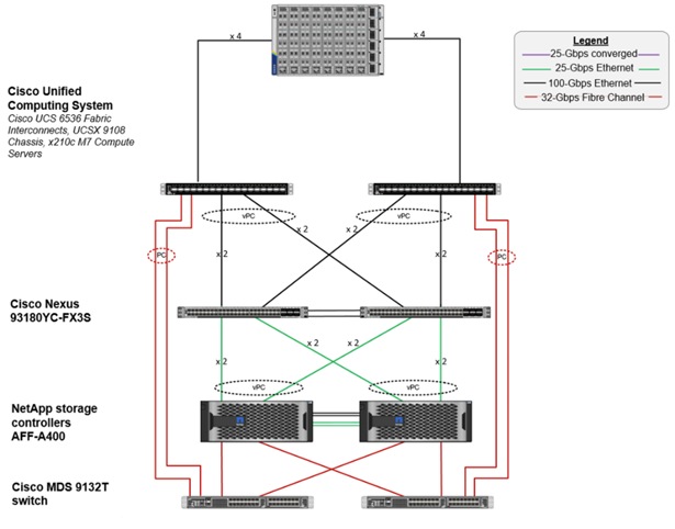
The reference hardware configuration includes:
● Two Cisco Nexus N9K-C93180YC-FX3S switches
● Two Cisco UCS 6536 Fabric Interconnects
● Eight Cisco UCS X210c M7 Compute Node Servers (for VDI workload)
● Infrastructure VMs for VDI were housed on an external cluster
● One NetApp AFF A400 Storage (high-availability pair) System
For desktop virtualization, the deployment includes Citrix Virtual Apps and Desktops Remote Desktop Session Hosts (RDSH) Sessions and Windows 11 virtual desktops running on VMware vSphere 8.0 U1.
The design is intended to provide a large-scale building block for Citrix Virtual Apps and Desktops Remote Desktop Session Hosted (RDSH) Sessions workloads consisting of Remote Desktops Server Hosted (RDSH) sessions with Windows Server 2022 hosted shared desktop sessions and Windows 11 non-persistent and persistent hosted desktops in the following:
● 2500 Random Hosted Shared (RDSH) Server 2022 user sessions with Microsoft Office 2021 (Citrix Provisioning Server)
● 2000 Random Pooled Windows 11 Desktops with Microsoft Office 2021 (Citrix Provisioning Server)
● 2000 Static Full Copy Windows 11 Desktops with Microsoft Office 2021 (MCS Full Clone virtual machines)
The data provided in this document will allow you to adjust the mix of Remote Desktop Server Hosted (RDSH) Sessions and Windows 11 Virtual Desktops to suit their environment. For example, additional Compute Node servers and chassis can be deployed to increase compute capacity, additional disk shelves can be deployed to improve I/O capability and throughput, and special hardware or software features can be added to introduce new features. This document guides you through the detailed steps for deploying the base architecture. This procedure explains everything from physical cabling to network, compute, and storage device configurations.
This Cisco Validated Design provides details for deploying a fully redundant, highly available 2500 seats workload virtual sessions /desktop solution with Citrix on a FlexPod Datacenter architecture. Configuration guidelines are provided that refer to the reader to which redundant component is being configured with each step. For example, storage controller 01 and storage controller 02 are used to identify the two AFF A400 storage controllers that are provisioned with this document, Cisco Nexus A or Cisco Nexus B identifies the pair of Cisco Nexus switches that are configured.
The Cisco UCS 6536 Fabric Interconnects are similarly configured. Additionally, this document details the steps for provisioning multiple Cisco UCS hosts, and these are identified sequentially: VM-Host-Infra-01, VM-Host-Infra-02, VM-Host-RDSH-01, VM-Host-VDI-01 and so on. Finally, to indicate that you should include information pertinent to your environment in a given step, <text> appears as part of the command structure.
This Cisco Validated Design prescribes a defined set of hardware and software that serves as an integrated foundation for both Microsoft Windows 11 virtual desktops and RDS server desktop sessions based on Microsoft Server 2022 The mixed workload solution includes Cisco UCS hardware and Data Platform software, Cisco Nexus switches, the Cisco Unified Computing System (Cisco UCS), Citrix Virtual Apps and Desktops and VMware vSphere software in a single package. The design is efficient such that the networking, computing, and storage components occupy 25 rack units footprint in an industry standard 42U rack. Port density on the Cisco Nexus switches and Cisco UCS Fabric Interconnects enables the networking components to accommodate multiple UCS clusters in a single Cisco UCS domain.
A key benefit of the Cisco Validated Design architecture is the ability to customize the environment to suit your requirements. A Cisco Validated Design scales easily as requirements and demand change. The unit can be scaled both up (adding resources to a Cisco Validated Design unit) and out (adding more Cisco Validated Design units).
The reference architecture detailed in this document highlights the resiliency, cost benefit, and ease of deployment of a hyper-converged desktop virtualization solution. A solution capable of consuming multiple protocols across a single interface allows for choice and investment protection because it truly is a wire-once architecture.
The combination of technologies from Cisco Systems, Inc. Citrix Systems, Inc, NetApp Inc, and VMware Inc. produced a highly efficient, robust, and affordable desktop virtualization solution for a virtual desktop, hosted shared desktop or mixed deployment supporting different use cases. Key components of the solution include the following:
● More power, same size. Cisco UCS X210c M7Compute Node Servers with Up to 2x 4th Gen Intel® Xeon® Scalable Processors (codenamed Sapphire Rapids) with up to 60 cores per processor with up to 8TB with 32 x 256GB DDR5-4800MT/s DIMMs, in a 2-sockets configuration with Citrix Virtual Apps and Desktops support more virtual desktop workloads than the previously released generation processors on the same hardware. The Intel 32-core processors used in this study provided a balance between increased per-server capacity and cost.
● Fault-tolerance with high availability built into the design. The various designs are based on multiple Cisco UCS X210c M7Compute Node Servers for virtual desktop and infrastructure workloads. The design provides N+1 server fault tolerance for every payload type tested.
● Stress-tested to the limits during aggressive boot scenario. The 2500 user Remote Desktop Server Hosted (RDSH) sessions and 2000 Windows 11 Virtual Desktops environment booted and registered with the Citrix Broker in under 10 minutes, providing you with an extremely fast, reliable cold-start desktop virtualization system.
● Stress-tested to the limits during simulated login storms. The 2500 user RDSH sessions and 2000 Windows 11 Virtual Desktops environment ready state in 48-minutes without overwhelming the processors, exhausting memory, or exhausting the storage subsystems, providing you with a desktop virtualization system that can easily handle the most demanding login and startup storms.
● Ultra-condensed computing for the datacenter. The rack space required to support the initial 2000 user system is 3 rack units, including Cisco Nexus Switching and Cisco Fabric interconnects. Incremental seat Cisco converged solutions clusters can be added one at a time to a total of 32 nodes.
● 100 percent virtualized This CVD presents a validated design that is 100 percent virtualized on VMware ESXi 8.0 U1. All of the virtual desktops, user data, profiles, and supporting infrastructure components, including Active Directory, SQL Servers, Citrix Virtual Apps and Desktops Connection Server components, Citrix VDI virtual desktops and RDSH servers were hosted as virtual machines.
● Cisco data center management: Cisco maintains industry leadership with the new Cisco Intersight 5.2(0.230041) software that simplifies scaling, guarantees consistency, and eases maintenance. Cisco’s ongoing development efforts with Cisco Intersight, Cisco UCS Central, and Cisco UCS Director ensure that your environments are consistent locally, across Cisco UCS Domains and across the globe. Cisco UCS software suite offers increasingly simplified operational and deployment management, and it continues to widen the span of control for your organizations’ subject matter experts in compute, storage, and network.
● Cisco 100G Fabric: Our 100G unified fabric story gets additional validation on 6500 Series Fabric Interconnects as Cisco runs more challenging workload testing, while maintaining unsurpassed user response times.
● NetApp AFF A400 array provides industry-leading storage solutions that efficiently handles the most demanding I/O bursts (for example, login storms), profile management, and user data management, deliver simple and flexible business continuance, and helps reduce storage cost per desktop. It also provides a simple to understand storage architecture for hosting all user data components (VMs, profiles, user data) on the same storage array.
● NetApp clustered Data ONTAP software enables to seamlessly add, upgrade, or remove storage from the infrastructure to meet the needs of the virtual desktops.
● Citrix Virtual Apps and Desktops advantage: Citrix Virtual Apps and Desktops follows a new unified product architecture that supports both Virtual Desktops and Remote Desktop Server Hosted server sessions. This new Citrix release simplifies tasks associated with large-scale VDI management. This modular solution supports seamless delivery of Windows apps and desktops as the number of user increase.
● Optimized for performance and scale. For hosted shared desktop sessions, the best performance was achieved when the number of vCPUs assigned to the Citrix RDS virtual machines did not exceed the number of hyper-threaded (logical) cores available on the server. In other words, maximum performance is obtained when not overcommitting the CPU resources for the virtual machines running virtualized RDS systems.
● Provisioning desktop machines made easy: Citrix Virtual Apps and Desktops provisions Remote Desktop Hosted Sessions (RDS) virtual desktops as well as hosted shared desktop virtual machines for this solution using a single method for both, the “Automated floating assignment desktop pool.” “Dedicated user assigned desktop pool” for persistent desktops was provisioned in the same Citrix administrative console. The new method of Instant Clone greatly reduces the amount of life-cycle spend and the maintenance windows for the guest OS.
This chapter contains the following:
● Cisco Unified Computing System
Cisco Unified Computing System
Cisco Unified Computing System (Cisco UCS) is a next-generation data center platform that integrates computing, networking, storage access, and virtualization resources into a cohesive system designed to reduce total cost of ownership and increase business agility. The system integrates a low-latency, lossless 10-100 Gigabit Ethernet unified network fabric with enterprise-class, x86-architecture servers. The system is an integrated, scalable, multi-chassis platform with a unified management domain for managing all resources.
Cisco Unified Computing System consists of the following subsystems:
● Compute - The compute piece of the system incorporates servers based on the Second-Generation INTEL Scalable processors. Servers are available in Compute Node and rack form factor, managed by Cisco Intersight.
● Network - The integrated network fabric in the system provides a low-latency, lossless, 10/25/40/100 Gbps Ethernet fabric. Networks for LAN, SAN and management access are consolidated within the fabric. The unified fabric uses the innovative Single Connect technology to lowers costs by reducing the number of network adapters, switches, and cables. This in turn lowers the power and cooling needs of the system.
● Virtualization - The system unleashes the full potential of virtualization by enhancing the scalability, performance, and operational control of virtual environments. Cisco security, policy enforcement, and diagnostic features are now extended into virtual environments to support evolving business needs.
● Storage access – Cisco UCS provides consolidated access to both SAN storage and Network Attached Storage over the unified fabric. This provides you with storage choices and investment protection. Also, the server administrators can pre-assign storage-access policies to storage resources, for simplified storage connectivity and management leading to increased productivity.
● Management: The system uniquely integrates compute, network, and storage access subsystems, enabling it to be managed as a single entity through Cisco Intersight software. Cisco Intersight increases IT staff productivity by enabling storage, network, and server administrators to collaborate on Service Profiles that define the desired physical configurations and infrastructure policies for applications. Service Profiles increase business agility by enabling IT to automate and provision resources in minutes instead of days.
Cisco Unified Computing System is revolutionizing the way servers are managed in the datacenter. The following are the unique differentiators of Cisco Unified Computing System and Cisco Intersight:
● Embedded Management — In Cisco UCS, the servers are managed by the embedded firmware in the fabric interconnects, eliminating the need for any external physical or virtual devices to manage the servers.
● Unified Fabric — In Cisco UCS, from Compute Node server chassis or rack servers to FI, there is a single Ethernet cable used for LAN, SAN, and management traffic. This converged I/O results in reduced cables, SFPs and adapters – reducing capital and operational expenses of the overall solution.
● Auto Discovery — By simply inserting the Compute Node server in the chassis or connecting the rack server to the fabric interconnect, discovery and inventory of compute resources occurs automatically without any management intervention. The combination of unified fabric and auto-discovery enables the wire-once architecture of Cisco UCS, where compute capability of Cisco UCS can be extended easily while keeping the existing external connectivity to LAN, SAN, and management networks.
● Policy Based Resource Classification — When Cisco Intersight discovers a compute resource, it can be automatically classified to a given resource pool based on policies defined. This capability is useful in multi-tenant cloud computing. This CVD highlights the policy-based resource classification of Cisco Intersight.
● Combined Rack and Compute Node Server Management — Cisco Intersight can manage Cisco UCS X-Series Compute Node Servers and Cisco UCS C-Series Rack Servers under the same Cisco UCS domain. This feature, along with stateless computing makes compute resources truly hardware form factor agnostic.
● Model based Management Architecture — The Cisco Intersight architecture and management database is model based, and data driven. An open XML API is provided to operate on the management model. This enables easy and scalable integration of Cisco Intersight with other management systems.
● Policies, Pools, Templates — The management approach in Cisco Intersight is based on defining policies, pools, and templates, instead of cluttered configuration, which enables a simple, loosely coupled, data driven approach in managing compute, network, and storage resources.
● Loose Referential Integrity — In Cisco Intersight, a server profile, port profile or policies can refer to other policies or logical resources with loose referential integrity. A referred policy cannot exist at the time of authoring the referring policy or a referred policy can be deleted even though other policies are referring to it. Profiles allow subject matter experts to work independently from one another, providing more flexibility for specialized skillsets in network, storage, security, server, and virtualization to collaborate and accomplish a complex task.
● Policy Resolution — In Cisco Intersight, a tree structure of organizational unit hierarchy can be created that mimics the real-life tenants and/or organization relationships. Various policies, pools and templates can be defined at different levels of organization hierarchy. A policy referring to another policy by name is resolved in the organizational hierarchy with closest policy match. If no policy with specific name is found in the hierarchy of the root organization, then the special policy named “default” is searched. This policy resolution practice enables automation friendly management APIs and provides great flexibility to owners of different organizations.
● Server Profiles and Stateless Computing — A service profile is a logical representation of a server, carrying its various identities and policies. This logical server can be assigned to any physical compute resource as far as it meets the resource requirements. Stateless computing enables procurement of a server within minutes, which used to take days in legacy server management systems.
● Built-in Multi-Tenancy Support — The combination of policies, pools and templates, loose referential integrity, policy resolution in the organizational hierarchy and a service profiles-based approach to compute resources makes Cisco Intersight inherently friendly to multi-tenant environments typically observed in private and public clouds.
● Extended Memory — The enterprise-class Cisco UCS Compute Node Server extends the capabilities of the Cisco Unified Computing System portfolio in a half-width Compute Node form factor. It harnesses the power of the latest INTEL Scalable Series processor family CPUs and Intel Optane DC Persistent Memory (DCPMM) with up to 18 TB of RAM (using 256GB DDR4 DIMMs and 512GB DCPMM).
● Simplified QoS — Even though Fibre Channel and Ethernet are converged in the Cisco UCS fabric, built-in support for QoS and lossless Ethernet makes it seamless. Network Quality of Service (QoS) is simplified in Cisco Intersight by representing all system classes in one GUI panel.
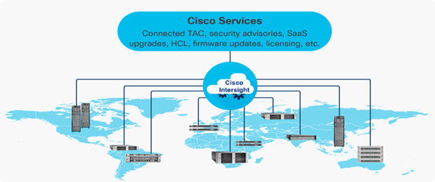
Cisco Intersight is a lifecycle management platform for your infrastructure, regardless of where it resides. In your enterprise data center, at the edge, in remote and branch offices, at retail and industrial sites—all these locations present unique management challenges and have typically required separate tools. Cisco Intersight Software as a Service (SaaS) unifies and simplifies your experience of the Cisco Unified Computing System (Cisco UCS).
Cisco Intersight software delivers a new level of cloud-powered intelligence that supports lifecycle management with continuous improvement. It is tightly integrated with the Cisco Technical Assistance Center (TAC). Expertise and information flow seamlessly between Cisco Intersight and IT teams, providing global management of Cisco infrastructure, anywhere. Remediation and problem resolution are supported with automated upload of error logs for rapid root-cause analysis.
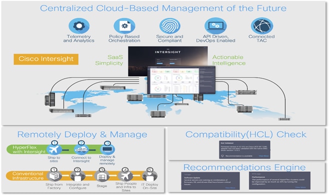
● Automate your infrastructure
Cisco has a strong track record for management solutions that deliver policy-based automation to daily operations. Intersight SaaS is a natural evolution of our strategies. Cisco designed Cisco UCS to be 100 percent programmable. Cisco Intersight simply moves the control plane from the network into the cloud. Now you can manage your Cisco UCS infrastructure wherever it resides through a single interface.
● Deploy your way
If you need to control how your management data is handled, comply with data locality regulations, or consolidate the number of outbound connections from servers, you can use the Cisco Intersight Virtual Appliance for an on-premises experience. Cisco Intersight Virtual Appliance is continuously updated just like the SaaS version, so regardless of which approach you implement, you never have to worry about whether your management software is up to date.
● DevOps ready
If you are implementing DevOps practices, you can use the Cisco Intersight API with either the cloud-based or virtual appliance offering. Through the API you can configure and manage infrastructure as code—you are not merely configuring an abstraction layer; you are managing the real thing. Through the API and support of cloud-based RESTful API, Terraform providers, Microsoft PowerShell scripts, or Python software, you can automate the deployment of settings and software for both physical and virtual layers. Using the API, you can simplify infrastructure lifecycle operations and increase the speed of continuous application delivery.
● Pervasive simplicity
◦ Simplify the user experience by managing your infrastructure regardless of where it is installed.
◦ Automate updates to Cisco UCS Data Platform software, reducing complexity and manual efforts.
● Actionable intelligence
◦ Use best practices to enable faster, proactive IT operations.
◦ Gain actionable insight for ongoing improvement and problem avoidance.
● Manage anywhere
◦ Deploy in the data center and at the edge with massive scale.
◦ Get visibility into the health and inventory detail for your Intersight Managed environment on-the-go with the Cisco Intersight Mobile App.
For more information about Cisco Intersight and the different deployment options, go to: Cisco Intersight – Manage your systems anywhere.
This chapter contains the following:
● Cisco UCS Fabric Interconnect
● Cisco Unified Computing System X-Series
● Citrix Virtual App and Desktops 7 2203 LTSR
● NetApp A-Series All Flash FAS
● Cisco Intersight Assist Device Connector for VMware vCenter and NetApp ONTAP
● NetApp ONTAP Tools for VMware vSphere
● NetApp NFS Plug-in for VMware VAAI
The Cisco UCS Fabric Interconnect (FI) is a core part of the Cisco Unified Computing System, providing both network connectivity and management capabilities for the system. Depending on the model chosen, the Cisco UCS Fabric Interconnect offers line-rate, low-latency, lossless 10 Gigabit, 25 Gigabit, 40 Gigabit, or 100 Gigabit Ethernet, Fibre Channel over Ethernet (FCoE) and Fibre Channel connectivity. Cisco UCS Fabric Interconnects provide the management and communication backbone for the Cisco UCS C-Series, Cisco UCS X-Series, Cisco UCS B-Series Blade Servers, and Cisco UCS Chassis. All servers and chassis, and therefore all Compute Nodes, attached to the Cisco UCS Fabric Interconnects become part of a single, highly available management domain. In addition, by supporting unified fabrics, the Cisco UCS Fabric Interconnects provide both the LAN and SAN connectivity for all servers within its domain.
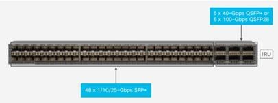
For networking performance, the Cisco UCS 6536 uses a cut-through architecture, supporting deterministic, low-latency, line-rate 10/25/40/100 Gigabit Ethernet ports, a switching capacity of 7.42 Tbps per FI and 14.84 Tbps per unified fabric domain, independent of packet size and enabled services. It enables 1600Gbps bandwidth per X9508 chassis with X9108-IFM-100G in addition to enabling end-to-end 100G ethernet and 200G aggregate bandwidth per X210c compute node. With the X9108-IFM-25G and the IOM 2408, it enables 400Gbps bandwidth per chassis per FI domain. The product family supports Cisco® low-latency, lossless 10/25/40/100 Gigabit Ethernet unified network fabric capabilities, which increases the reliability, efficiency, and scalability of Ethernet networks. The 6536 Fabric Interconnect supports multiple traffic classes over a lossless Ethernet fabric from the server through the fabric interconnect. Significant TCO savings come from the Unified Fabric optimized server design in which Network Interface Cards (NICs), Host Bus Adapters (HBAs), cables, and switches can be consolidated.
Cisco UCS 6536 Fabric Interconnects
The Cisco UCS Fabric Interconnects (FIs) provide a single point for connectivity and management for the entire Cisco Unified Computing System. Typically deployed as an active/active pair, the system’s FIs integrate all components into a single, highly available management domain controlled by Cisco Intersight. Cisco UCS FIs provide a single unified fabric for the system, with low-latency, lossless, cut-through switching that supports LAN, SAN, and management traffic using a single set of cables.
![]()
The Cisco UCS 6536 36-Port Fabric Interconnect (Figure 5) is a One-Rack-Unit (1RU) 1/10/25/40/100 Gigabit Ethernet, FCoE, and Fibre Channel switch offering up to 7.42 Tbps throughput and up to 36 ports. The switch has 32 40/100-Gbps Ethernet ports and 4 unified ports that can support 40/100-Gbps Ethernet ports or 16 Fiber Channel ports after breakout at 8/16/32-Gbps FC speeds.
Cisco Unified Computing System X-Series
The Cisco UCS X-Series Modular System is designed to take the current generation of the Cisco UCS platform to the next level with its future-ready design and cloud-based management. Decoupling and moving the platform management to the cloud allows Cisco UCS to respond to your feature and scalability requirements in a much faster and efficient manner. Cisco UCS X-Series state of the art hardware simplifies the data-center design by providing flexible server options. A single server type, supporting a broader range of workloads, results in fewer different data center products to manage and maintain. The Cisco Intersight cloud-management platform manages Cisco UCS X-Series as well as integrates with third-party devices, including VMware vCenter and NetApp storage, to provide visibility, optimization, and orchestration from a single platform, thereby driving agility and deployment consistency.
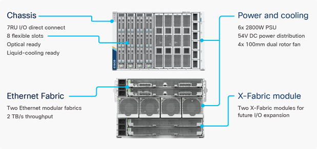
Cisco UCS X9508 Chassis
The Cisco UCS X-Series chassis is engineered to be adaptable and flexible. As seen in Figure 7, the Cisco UCS X9508 chassis has only a power-distribution midplane. This midplane-free design provides fewer obstructions for better airflow. For I/O connectivity, vertically oriented compute nodes intersect with horizontally oriented fabric modules, allowing the chassis to support future fabric innovations. Cisco UCS X9508 Chassis’ superior packaging enables larger compute nodes, thereby providing more space for actual compute components, such as memory, GPU, drives, and accelerators. Improved airflow through the chassis enables support for higher power components, and more space allows for future thermal solutions (such as liquid cooling) without limitations.
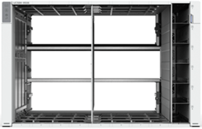
The Cisco UCS X9508 7-Rack-Unit (7RU) chassis has eight flexible slots. These slots can house a combination of compute nodes and a pool of current and future I/O resources that includes GPU accelerators, disk storage, and nonvolatile memory. At the top rear of the chassis are two Intelligent Fabric Modules (IFMs) that connect the chassis to upstream Cisco UCS 6400 or 6500 Series Fabric Interconnects. At the bottom rear of the chassis are slots to house X-Fabric modules that can flexibly connect the compute nodes with I/O devices. Six 2800W Power Supply Units (PSUs) provide 54V power to the chassis with N, N+1, and N+N redundancy. A higher voltage allows efficient power delivery with less copper and reduced power loss. Efficient, 100mm, dual counter-rotating fans deliver industry-leading airflow and power efficiency, and optimized thermal algorithms enable different cooling modes to best support your environment.
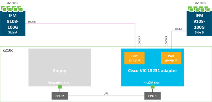
Cisco UCSX-I-9108-100G Intelligent Fabric Modules
In the end-to-end 100Gbps Ethernet design, for the Cisco UCS X9508 Chassis, the network connectivity is provided by a pair of Cisco UCSX-I-9108-100G Intelligent Fabric Modules (IFMs). Like the fabric extenders used in the Cisco UCS 5108 Blade Server Chassis, these modules carry all network traffic to a pair of Cisco UCS 6536 Fabric Interconnects (FIs). IFMs also host the Chassis Management Controller (CMC) for chassis management. In contrast to systems with fixed networking components, Cisco UCS X9508’s midplane-free design enables easy upgrades to new networking technologies as they emerge making it straightforward to accommodate new network speeds or technologies in the future.
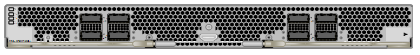
Each IFM supports eight 100Gb uplink ports for connecting the Cisco UCS X9508 Chassis to the FIs and 8 100Gb or 32 25Gb server ports for the eight compute nodes. IFM server ports can provide up to 200 Gbps of unified fabric connectivity per compute node across the two IFMs. The uplink ports connect the chassis to the Cisco UCS FIs, providing up to 1600Gbps connectivity across the two IFMs. The unified fabric carries management, VM, and Fibre Channel over Ethernet (FCoE) traffic to the FIs, where server management traffic is routed to the Cisco Intersight cloud operations platform, FCoE traffic is forwarded to either native Fibre Channel interfaces through unified ports on the FI (to Cisco MDS switches) or to FCoE uplinks (to Cisco Nexus switches supporting SAN switching), and data Ethernet traffic is forwarded upstream to the data center network (using Cisco Nexus switches).
Cisco UCS X210c M7 Compute Node
The Cisco UCS X9508 Chassis is designed to host up to 8 Cisco UCS X210c M7 or X210c M6 Compute Nodes. The hardware details of the Cisco UCS X210c M7 Compute Nodes are shown in Figure 9:
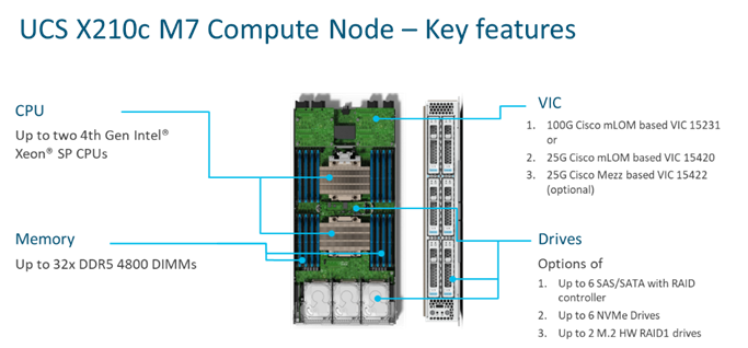
The Cisco UCS X210c M7 features:
● CPU: Up to 2x 4th Gen Intel Xeon Scalable Processors with up to 60 cores per processor and 2.625 MB Level 3 cache per core and up to 112.5 MB per CPU.
● Memory: Up to 32 x 256 GB DDR5-4800 DIMMs for a maximum of 8 TB of main memory.
● Disk storage: Up to 6 SAS or SATA drives or NVMe drives can be configured with the choice of an internal RAID controller or passthrough controllers. 2 M.2 memory cards can be added to the Compute Node with optional hardware RAID.
● GPUs: The optional front mezzanine GPU module allows support for up to two HHHL GPUs. Adding a mezzanine card and a Cisco UCS X440p PCIe Node allows up to four more GPUs to be supported with an X210c M7.
● Virtual Interface Card (VIC): Up to 2 VICs including an mLOM Cisco UCS VIC 15231 or an mLOM Cisco UCS VIC 15420 and a mezzanine Cisco UCS VIC card 15422 can be installed in a Compute Node.
● Security: The server supports an optional Trusted Platform Module (TPM). Additional security features include a secure boot FPGA and ACT2 anticounterfeit provisions.
Cisco UCS Virtual Interface Cards (VICs)
Cisco UCS X210c M7 Compute Nodes support the following Cisco UCS VIC cards:
Cisco UCS VIC 15231
Cisco UCS VIC 15231 fits the mLOM slot in the Cisco UCS X210c Compute Node and enables up to 100 Gbps of unified fabric connectivity to each of the chassis IFMs for a total of 200 Gbps of connectivity per server. Cisco UCS VIC 15231 connectivity to the IFM and up to the fabric interconnects is delivered through 100Gbps. Cisco UCS VIC 15231 supports 512 virtual interfaces (both FCoE and Ethernet) along with the latest networking innovations such as NVMeoF over FC or TCP, VxLAN/NVGRE offload, and so forth.
Cisco Nexus N9K-C93180YC-FX3S Switches
The N9K-C93180YC-FX3S Switch provides a flexible line-rate Layer 2 and Layer 3 feature set in a compact form factor. Designed with Cisco Cloud Scale technology, it supports highly scalable cloud architectures. With the option to operate in Cisco NX-OS or Application Centric Infrastructure (ACI) mode, it can be deployed across enterprise, service provider, and Web 2.0 data centers.
● Architectural Flexibility
◦ Includes top-of-rack or middle-of-row fiber-based server access connectivity for traditional and leaf-spine architectures
◦ Leaf node support for Cisco ACI architecture is provided in the roadmap
◦ Increase scale and simplify management through Cisco Nexus 2000 Fabric Extender support
● Feature Rich
◦ Enhanced Cisco NX-OS Software is designed for performance, resiliency, scalability, manageability, and programmability
◦ ACI-ready infrastructure helps users take advantage of automated policy-based systems management
◦ Virtual Extensible LAN (VXLAN) routing provides network services
◦ Rich traffic flow telemetry with line-rate data collection
◦ Real-time buffer utilization per port and per queue, for monitoring traffic micro-bursts and application traffic patterns
● Highly Available and Efficient Design
◦ High-density, non-blocking architecture
◦ Easily deployed into either a hot-aisle and cold-aisle configuration
◦ Redundant, hot-swappable power supplies and fan trays
● Simplified Operations
◦ Power-On Auto Provisioning (POAP) support allows for simplified software upgrades and configuration file installation
◦ An intelligent API offers switch management through remote procedure calls (RPCs, JSON, or XML) over a HTTP/HTTPS infrastructure
◦ Python Scripting for programmatic access to the switch command-line interface (CLI)
◦ Hot and cold patching, and online diagnostics
The Cisco Intersight platform is a Software-as-a-Service (SaaS) infrastructure lifecycle management platform that delivers simplified configuration, deployment, maintenance, and support. The Cisco Intersight platform is designed to be modular, so you can adopt services based on their individual requirements. The platform significantly simplifies IT operations by bridging applications with infrastructure, providing visibility and management from bare-metal servers and hypervisors to serverless applications, thereby reducing costs and mitigating risk. This unified SaaS platform uses a unified Open API design that natively integrates with third-party platforms and tools.
The main benefits of Cisco Intersight infrastructure services are as follows:
● Simplify daily operations by automating many daily manual tasks
● Combine the convenience of a SaaS platform with the capability to connect from anywhere and manage infrastructure through a browser or mobile app
● Stay ahead of problems and accelerate trouble resolution through advanced support capabilities
● Gain global visibility of infrastructure health and status along with advanced management and support capabilities
● Upgrade to add workload optimization and Kubernetes services when needed
Cisco Intersight Virtual Appliance and Private Virtual Appliance
In addition to the SaaS deployment model running on Intersight.com, on-premises options can be purchased separately. The Cisco Intersight Virtual Appliance and Cisco Intersight Private Virtual Appliance are available for organizations that have additional data locality or security requirements for managing systems. The Cisco Intersight Virtual Appliance delivers the management features of the Cisco Intersight platform in an easy-to-deploy VMware Open Virtualization Appliance (OVA) or Microsoft Hyper-V Server virtual machine that allows you to control the system details that leave your premises. The Cisco Intersight Private Virtual Appliance is provided in a form factor specifically designed for users who operate in disconnected (air gap) environments. The Private Virtual Appliance requires no connection to public networks or back to Cisco to operate.
Cisco Intersight Assist
Cisco Intersight Assist helps you add endpoint devices to Cisco Intersight. A data center could have multiple devices that do not connect directly with Cisco Intersight. Any device that is supported by Cisco Intersight, but does not connect directly with it, will need a connection mechanism. Cisco Intersight Assist provides that connection mechanism. In FlexPod, VMware vCenter and NetApp Active IQ Unified Manager connect to Intersight with the help of Intersight Assist VM.
Cisco Intersight Assist is available within the Cisco Intersight Virtual Appliance, which is distributed as a deployable virtual machine contained within an Open Virtual Appliance (OVA) file format. More details about the Cisco Intersight Assist VM deployment configuration is covered in later sections.
Licensing Requirements
Cisco Intersight requires physical servers to belong to a Licensing tier. This can be done by providing a default tier or setting it individually from Servers View. The enforcement of Cisco Infrastructure Services licenses occurs at the server level and is not dependent on UCS domains. All servers with valid licenses can use the licensed features.
The following table lists the features and tiers of the Cisco Infrastructure Services license:
| Category |
Feature |
Essentials |
Advantage |
| Lifecycle Operations |
Global Monitoring and Inventory |
✔ |
✔ |
| Custom Dashboards |
✔ |
✔ |
|
| Policy-based configuration with Server Profiles |
✔ |
✔ |
|
| Firmware Management |
✔ |
✔ |
|
| HCL for Compliance |
✔ |
✔ |
|
| 3rd party Server Ops |
✔ |
✔ |
|
| UCS Manager & UCS Central Entitlements |
✔ |
✔ |
|
| Proactive Support |
Proactive RMA |
✔ |
✔ |
| Connected TAC |
✔ |
✔ |
|
| Advisories |
✔ |
✔ |
|
| Sustainability (Power Policy Management for Servers, BIOS and OS, Dynamic power Rebalancing) |
✔ |
✔ |
|
| In-Platform Automation |
Tunneled vKVM |
|
✔ |
| Operating System Install Automation |
|
✔ |
|
| Storage/Virtualization/Network Automation |
|
✔ |
|
| Workflow Designer |
|
✔ |
|
| Ecosystem Integrations |
Ecosystem Visibility and Operations. Network (Nexus, MDS), Storage (NetApp, Pure Storage, Hitachi, Cohesity), Hybrid Cloud (VMware, Red Hat), Automation (Ansible, Terraform) |
|
✔ |
| ITOM Integrations (ServiceNow) |
|
✔ |
For more information about the features supported on various platforms, see Supported Systems.
Citrix Virtual App and Desktops 7 2203 LTSR
The virtual app and desktop solution is designed for an exceptional experience.
Today's employees spend more time than ever working remotely, causing companies to rethink how IT services should be delivered. To modernize infrastructure and maximize efficiency, many are turning to desktop as a service (DaaS) to enhance their physical desktop strategy, or they are updating on-premises virtual desktop infrastructure (VDI) deployments. Managed in the cloud, these deployments are high-performance virtual instances of desktops and apps that can be delivered from any datacenter or public cloud provider.
DaaS and VDI capabilities provide corporate data protection as well as an easily accessible hybrid work solution for employees. Because all data is stored securely in the cloud or datacenter, rather than on devices, end-users can work securely from anywhere, on any device, and over any network—all with a fully IT-provided experience. IT also gains the benefit of centralized management, so they can scale their environments quickly and easily. By separating endpoints and corporate data, resources stay protected even if the devices are compromised.
As a leading VDI and DaaS provider, Citrix provides the capabilities organizations need for deploying virtual apps and desktops to reduce downtime, increase security, and alleviate the many challenges associated with traditional desktop management.
Powered by NetApp ONTAP data management software and NetApp AFF A-Series systems (NetApp AFF) to deliver the industry’s highest performance, superior flexibility, and best-in-class data services and cloud integration to help accelerate, manage, and protect business-critical data across the hybrid cloud. It is a robust scale-out platform built for virtualized environments, combining low-latency performance with best-in-class data management, built-in efficiencies, integrated data protection, multiprotocol support, and nondisruptive operations. Deploy as a stand-alone system or as a high-performance tier in a NetApp ONTAP configuration.
A wide range of organizations, from enterprise to midsize businesses, rely on NetApp AFF A-Series to:
● Simplify operations with seamless data management, on the premises and in the cloud
● Accelerate traditional and new-generation applications
● Keep business-critical data available, protected, and secure
● Accelerates applications and future-proofs your infrastructure
In the modern data center, IT is charged with driving maximum performance for business-critical workloads, scaling without disruption as the business grows, and enabling the business to take on new data-driven initiatives. NetApp AFF A-Series systems handle all of it with ease.
The NetApp AFF A-Series lineup includes the A150, A250, A400, A700, A800 and A900. These controllers and their technical specifications are listed in Table 1. For more information about the NetApp A-Series AFF controllers, see:
http://www.netapp.com/us/products/storage-systems/all-flash-array/aff-a-series.aspx
https://hwu.netapp.com/Controller/Index?platformTypeId=5265148
Table 1. NetApp AFF Technical Specifications
| Specifications |
AFF A150 |
AFF A250 |
AFF A400 |
AFF A800 |
AFF A900 |
| Maximum scale-out |
2–24 nodes (12 HA pairs) |
2-24 nodes (12 HA pair) |
2-24 nodes (12 HA pair) |
2-24 nodes (12 HA pair) |
2-24 nodes (12 HA pair) |
| Maximum SSDs |
864 |
576 |
5760 |
2880 |
5760 |
| Max effective capacity |
26PB |
35PB |
702.7PB |
316.3PB |
702.7PB |
| Controller form factor |
2U; 24 internal SSD slots |
2U |
4U |
4U with 48 SSD slots |
8U |
| PCIe expansion slots |
n/a |
4 |
10 |
8 |
20 |
| FC target ports (32Gb autoranging) |
n/a |
16 |
24 |
32 |
64 |
| FC target ports (16Gb autoranging) |
n/a |
n/a |
32(with FC mezzanine card) |
32 |
64 |
| FCoE target ports, UTA2 |
8 |
n/a |
n/a |
n/a |
64 |
| 100GbE ports (40GbE autoranging) |
n/a |
4 |
16 |
20 |
32 |
| 25GbE ports (10GbE autoranging) |
n/a |
20 |
16 |
16 |
64 |
| 10GbE ports |
4 |
n/a |
32 |
32 |
64 |
| 12Gb/6Gb SAS ports |
4 |
8 |
32 |
n/a |
64 |
| Storage networking supported |
NVMe/TCP, FC, iSCSI, NFS, pNFS, CIFS/SMB, Amazon S3 |
NVMe/TCP, NVMe/FC, FC, iSCSI, NFS, pNFS, CIFS/SMB, Amazon s3 |
NFSv4/RDMA, NVMe/TCP, NVMe/FC, FC, iSCSI, NFS, pNFS, CIFS/SMB, Amazon s3 |
NFSv4/RDMA, NVMe/TCP, NVMe/FC, FC, iSCSI, NFS, pNFS, CIFS/SMB, Amazon s3 |
NVMe/TCP, NVMe/FC, FC, iSCSI, NFS, pNFS, CIFS/SMB, Amazon s3 |
| OS version |
ONTAP 9.12 1P1 or later |
ONTAP 9.8 RC1 or later |
ONTAP 9.7 RC1 or later |
ONTAP 9.7 RC1 or later |
ONTAP 9.10.1 RC2 or later |
The following are few advantages of NetApp AFF A-Series:
● Maximum performance for your most demanding applications:
◦ NetApp AFF A-Series systems deliver industry-leading performance proven by SPC-1 and SPEC SFS industry benchmarks, making them ideal for demanding, highly transactional applications such as Oracle, Microsoft SQL Server, MongoDB databases, VDI, and server virtualization.
◦ With the power of front-end NVMe/FC and NVMe/TCP host connectivity and back-end NVMe-attached SSDs, our high-end AFF A900 systems deliver latency as low as 100µs. Based on a high-resiliency design, the A900 also delivers high RAS and enables non-disruptive in-chassis upgrade from its predecessor A700. The A800 delivers high performance in a compact form factor and is especially suited for EDA and Media and Entertainment workloads. The midrange, most versatile NetApp AFF A400 system features hardware acceleration technology that significantly enhances performance and storage efficiency. And our entry-level, budget-friendly NetApp AFF A400, provides 40% more performance and 33% more efficiency at no extra cost compared with its predecessor.
● NetApp AFF A-Series also lets you:
◦ Drive mission-critical SAN workloads with symmetric active-active host connectivity for continuous availability and instant failover.
◦ Consolidate workloads to deliver up to 14.4 million IOPS at 1ms latency in a cluster with a truly unified scale-out architecture. Built-in adaptive quality of service (QoS) safeguards SLAs in multi-workload and multitenant environments.
◦ Manage massively scalable NAS containers of up to 20PB and 400 billion files with a single namespace.
◦ Improve the speed and productivity of collaboration across multiple locations and increase data throughput for read-intensive applications with NetApp FlexCache software.
◦ Modernize with advanced connectivity
NetApp AFF A-Series all-flash systems deliver industry-leading performance, density, scalability, security, and network connectivity. As the first enterprise-grade storage systems to support both NVMe/TCP and NVMe/FC, NetApp AFF A-Series systems boost performance with modern network connectivity. With NVMe/TCP, which uses the commonly available Ethernet infrastructure, you don’t have to invest in new hardware to take advantage of the faster host connectivity. With NVMe/FC, you can get twice the IOPS and cut application response time in half compared with traditional FC. These systems support a range of ecosystems, including VMware, Microsoft Windows 11, and Linux, with storage path failover. For most, integrating NVMe/FC into an existing SAN is a simple, nondisruptive software upgrade.
● Scale without disruption
With NetApp AFF A-Series, you can integrate new technologies and private or public cloud into your infrastructure nondisruptively. NetApp AFF A-Series is the only all-flash array that enables you to combine different controllers, SSD sizes, and new technologies so that your investment is protected. The NVMe-based AFF systems also support SAS SSDs, maximizing the flexibility and cost effectiveness of your upgrade:
◦ Best balance between price, technology, features, and performance.
◦ Increase operational efficiency
IT departments are striving to make budgets go further and to allow IT staff to focus on new value-added projects rather than on day-to-day IT management. NetApp AFF systems simplify IT operations, which therefore reduces data center cost. In particular, the entry-level system, the NetApp AFF A400, delivers best-in-class performance and efficiency to mid-size businesses so they can consolidate more workloads and eliminate silos.
● Provision storage in minutes
NetApp AFF systems offer broad application ecosystem support and deep integration for enterprise applications, virtual desktop infrastructure (VDI), database, and server virtualization, supporting Oracle, Microsoft SQL Server, VMware, SAP, MySQL, and more. You can quickly provision storage in less than 10 minutes with NetApp ONTAP System Manager. In addition, infrastructure management tools simplify and automate common storage tasks so you can:
◦ Easily provision and rebalance workloads by monitoring clusters and nodes.
◦ Use one-click automation and self-service for provisioning and data protection.
◦ Upgrade OS and firmware with a single-click
◦ Import LUNs from third-party storage arrays directly into an AFF system to seamlessly migrate data.
Additionally, the NetApp Active IQ Digital Advisor engine enables you to optimize your NetApp systems with predictive analytics and proactive support. Fueled by the massive NetApp user base, AI and machine learning create actionable insights that help you prevent problems, optimize your configuration, save time, and make smarter decisions.
● Achieve outstanding storage savings
NetApp employs various capabilities to promote optimal capacity savings and to drive down your TCO. AFF A-Series system’s support for solid-state drives (SSDs) with multistream write technology, combined with advanced SSD partitioning, provides maximum usable capacity, regardless of the type of data that you store. Thin provisioning; NetApp Snapshot copies; and inline data reduction features, such as deduplication, compression, and compaction, provide substantial additional space savings—without affecting performance—enabling you to purchase the least amount of storage capacity possible.
● Build your hybrid cloud with ease
Your data fabric built by NetApp helps you simplify and integrate data management across cloud and on-premises environments to meet business demands and gain a competitive edge. With AFF A-Series, you can connect to more clouds for more data services, data tiering, caching, and disaster recovery. You can also:
◦ Maximize performance and reduce overall storage costs by automatically tiering cold data to the cloud with FabricPool
◦ Instantly deliver data to support efficient collaboration across your hybrid cloud
◦ Protect your data by taking advantage of Amazon Simple Storage Service (Amazon S3) cloud resources—on premises and in the public cloud
◦ Accelerate read performance for data that is shared widely throughout your organization and across hybrid cloud deployments
◦ Keep data available, protected, and secure
As organizations become more data driven, the business impact of data loss can be increasingly dramatic—and costly. IT must protect data from both internal and external threats, ensure data availability, eliminate maintenance disruptions, and quickly recover from failures.
● Integrated data protection
NetApp AFF A-Series systems come with a full suite of acclaimed NetApp integrated and application-consistent data protection software. Key capabilities include:
◦ Native space efficiency with cloning and NetApp Snapshot copies reduce storage costs and minimize performance impact. Up to 1,023 copies are supported.
◦ NetApp SnapCenter software provides application-consistent data protection and clone management to simplify application management.
◦ NetApp SnapMirror technology replicates to any NetApp FAS or AFF system on the premises or in the cloud, reducing overall system costs.
● Business continuity and fast disaster recovery
With NetApp AFF, you can maintain constant data availability with zero data loss and zero downtime. NetApp MetroCluster software provides synchronous replication to protect your entire system, and NetApp SnapMirror Business Continuity provides a more flexible, cost-effective business continuity to even with more granular replication of selected critical data.
● Security everywhere
Flexible encryption and key management help guard your sensitive data on the premises, in the cloud, and in transit. The market-leading anti-ransomware protection for both preemption and post-attack recovery safeguards your critical data from ransomware attacks and can prevent catastrophic financial consequences. With the simple and efficient security solutions, you can:
◦ Achieve FIPS 140-2 compliance (Level 1 and Level 2) with self-encrypting drives and use any type of drives with software-based encryption
◦ Meet governance, risk, and compliance requirements with security features such as secure purge; logging and auditing monitors; and write once, read many (WORM) file locking
◦ Protect against threats with multifactor authentication, role-based access control, secure multitenancy, and storage-level file security
NetApp AFF A400
The NetApp AFF A400 provides full end-to-end NVMe support. The frontend FC-NVMe connectivity makes it possible to achieve optimal performance from an all-flash array for workloads that include artificial intelligence, machine learning, and real-time analytics as well as business-critical databases. The frontend NVMe-TCP connectivity enables customers to take advantage of NVMe technology over existing ethernet infrastructure for faster host connectivity. On the back end, the A400 supports both serial-attached SCSI (SAS) and NVMe-attached SSDs, offering the versatility for current customers to move up from their legacy A-Series systems and satisfying the increasing interest that all customers have in NVMe-based storage.
The NetApp AFF A400 has greater port availability, network connectivity, and expandability. The NetApp AFF A400 has 10 PCIe Gen3 slots per high availability pair. The NetApp AFF A400 is available with 10GbE, 25GbE or 100GbE, as well as 16/32Gb/FC and NVMe/FC network connectivity. This model was created to keep up with changing business needs and performance and workload requirements by merging the latest technology for data acceleration and ultra-low latency in an end-to-end NVMe storage system.

Note: We used 4 port 32Gb FC HBA on slot 1 (1a,1b, other two ports unused) for front-end FC SAN connection, 4x25Gb Ethernet NICs on slot 0 (e0e, e0f, e0g, e0h) for NAS connectivity, 2x100Gb ethernet ports on slot 3 (e3a, e3b) used for cluster interconnect, 2x25Gb ethernet on slot 0 (e0a, e0b) used for Node HA interconnect, 2x100Gb ethernet on slot 0 (e0c, e0d) and 2x100Gb ethernet on slot 5 (e5a, e5b) are used for backend NVMe storage connectivity.
NetApp AFF C-Series Storage
The NetApp AFF C-Series all-flash systems are ideal for tier 1 and tier 2 workloads while also delivering better performance than disks. These systems are suited for large-capacity deployment with a small footprint as an affordable way to modernize data center to all flash and also connect to the cloud. Powered by NetApp ONTAP data management software, NetApp AFF C-Series systems deliver industry-leading efficiency, superior flexibility, and best-in-class data services and cloud integration to help scale IT infrastructure, simplify data management, reduce storage cost, rack space usage, power consumption, and improve sustainability significantly. NetApp offers several AFF C-series controllers to meet varying demands of the field. The high-end NetApp AFF C800 systems offer superior performance. The midrange NetApp AFF C400 delivers high performance and good expansion capability. The entry-level NetApp AFF C250 systems provide balanced performance, connectivity, and expansion options for a small footprint deployment.
For more information about the NetApp AFF C-series controllers, see the NetApp AFF C-Series product page: https://www.netapp.com/data-storage/aff-c-series/
You can view or download more technical specifications of the NetApp AFF C-Series controllers here: https://www.netapp.com/media/81583-da-4240-aff-c-series.pdf
You can look up the detailed NetApp storage product configurations and limits here: https://hwu.netapp.com/
FlexPod CVDs provide reference configurations and there are many more supported IMT configurations that can be used for FlexPod deployments, including NetApp hybrid storage arrays.
NetApp ASA (All-flash SAN Array)
NetApp ASA, a family of modern all-flash block storage that’s designed for customers who need resilient, high-throughput, low-latency solutions for their mission-critical workloads. Many businesses see the benefit of SAN solutions. Especially when every minute of downtime can cost hundreds of thousands of dollars, or when poor performance prevents you from fulfilling your mission. Unified storage is often a convenient consolidated solution for file and block workloads, but customers might prefer a dedicated SAN system to isolate these workloads from others. NetApp ASA is block optimized and supports NVMe/TCP and NVMe/FC as well as standard FC and iSCSI protocols. Building upon the foundation of well-architected SAN, ASA offers your organization the following benefits:
● Six nines (99.9999%) availability that’s backed by an industry-leading 6 Nines Data Availability Guarantee
● Massive scalability with the NetApp ONTAP cluster capability, which enables you to scale out ASA storage to more than 350PB of effective capacity
● Industry-leading storage efficiency that’s built-in and supported by a simple, straightforward Storage Efficiency Guarantee
● The most comprehensive cloud connectivity available
● Cost-effective integrated data protection
For more information about NetApp ASA, see the NetApp ASA product page: https://www.netapp.com/data-storage/all-flash-san-storage-array/
You can view or download more technical specifications of the NetApp ASA controllers here: https://www.netapp.com/media/87298-NA-1043-0523_ASA_AFF_Tech_Specs_HR.pdf
NetApp ONTAP 9
NetApp storage systems harness the power of ONTAP to simplify the data infrastructure from edge, core, and cloud with a common set of data services and 99.9999 percent availability. NetApp ONTAP 9 data management software from NetApp enables you to modernize your infrastructure and transition to a cloud-ready data center. NetApp ONTAP 9 has a host of features to simplify deployment and data management, accelerate and protect critical data, and make infrastructure future-ready across hybrid-cloud architectures.
NetApp ONTAP 9 is the data management software that is used with the NetApp AFF A400 all-flash storage system in this solution design. NetApp ONTAP software offers secure unified storage for applications that read and write data over block- or file-access protocol storage configurations. These storage configurations range from high-speed flash to lower-priced spinning media or cloud-based object storage. NetApp ONTAP implementations can run on NetApp engineered AFF, FAS or ASA series arrays and in private, public, or hybrid clouds (NetApp Private Storage and NetApp Cloud Volumes ONTAP). Specialized implementations offer best-in-class converged infrastructure, featured here as part of the FlexPod Datacenter solution or with access to third-party storage arrays (NetApp FlexArray virtualization). Together these implementations form the basic framework of the NetApp Data Fabric, with a common software-defined approach to data management, and fast efficient replication across systems. FlexPod and ONTAP architectures can serve as the foundation for both hybrid cloud and private cloud designs.
Read more about all the capabilities of ONTAP data management software here: https://www.netapp.com/us/products/data-management-software/ontap.aspx.
NetApp ONTAP 9.13.1P3
NetApp ONTAP Features for VDI
The following are the NetApp ONTAP features for VDI:
● Secure Multi-Tenancy—Tenants can be in overlapping subnet or can use identical IP subnet range.
● Multi-Protocol—Same storage system can be used for Block/File/Object storage demands.
● FlexGroup Volumes—High performance and massive capacity (~20PB and ~40 billion files) for file shares and for hosting VDI pools.
● FlexCache—Enables Single Global Namespace can be consumed around the clouds or multi-site.
● File System Analytics—Fast query to file metadata on the SMB file share.
● Ease of management with vCenter Plugins—Best practices are validated and implemented while provisioning. Supports VAAI and VASA for fast provisioning and storage capability awareness.
● SnapCenter integration with vCenter—Space efficient data protection with snapshots and FlexClones.
● Automation support—Supports RESTapi, has modules for Ansible, PowerShell, and so on.
● Storage Efficiency—Supports inline dedupe, compression, thin provisioning, and so on. Guaranteed dedupe of 8:1 for VDI.
● Adaptive QoS—Adjusts QoS setting based on space consumption.
● ActiveIQ Unified Manager—Application based storage provisioning, Performance Monitoring, End-End storage visibility diagrams.
Storage efficiency has always been a primary architectural design point of ONTAP. A wide array of features allows businesses to store more data using less space. In addition to deduplication and compression, businesses can store their data more efficiently by using features such as unified storage, multi-tenancy, thin provisioning, and NetApp Snapshot technology.
Starting with ONTAP 9, NetApp guarantees that the use of NetApp storage efficiency technologies on AFF systems reduce the total logical capacity used to store your data by 75 percent, a data reduction ratio of 4:1. This space reduction is a combination of several different technologies, such as deduplication, compression, and compaction, which provide additional reduction to the basic features provided by ONTAP.
Compaction, which is introduced in ONTAP 9, is the latest patented storage efficiency technology released by NetApp. In the NetApp WAFL file system, all I/O takes up 4KB of space, even if it does not actually require 4KB of data. Compaction combines multiple blocks that are not using their full 4KB of space together into one block. This one block can be more efficiently stored on the disk-to-save space. This process is illustrated in Figure 12.
Storage Efficiency Features
The storage efficiency features are as follows:
Deduplication reduces the amount of physical storage required for a volume (or all the volumes in an AFF aggregate) by discarding duplicate blocks and replacing them with references to a single shared block. Reads of deduplicated data typically incur no performance charge. Writes incur a negligible charge except on overloaded nodes.
As data is written during normal use, WAFL uses a batch process to create a catalog of block signatures. After deduplication starts, ONTAP compares the signatures in the catalog to identify duplicate blocks. If a match exists, a byte-by-byte comparison is done to verify that the candidate blocks have not changed since the catalog was created. Only if all the bytes match is the duplicate block discarded and its disk space reclaimed.
● Compression
Compression reduces the amount of physical storage required for a volume by combining data blocks in compression groups, each of which is stored as a single block. Reads of compressed data are faster than in traditional compression methods because ONTAP decompresses only the compression groups that contain the requested data, not an entire file or LUN.
You can perform inline or postprocess compression, separately or in combination:
◦ Inline compression compresses data in memory before it is written to disk, significantly reducing the amount of write I/O to a volume, but potentially degrading write performance. Performance-intensive operations are deferred until the next postprocess compression operation, if any.
◦ Postprocess compression compresses data after it is written to disk, on the same schedule as deduplication.
◦ Compaction
◦ Small files or I/O padded with zeros are stored in a 4 KB block whether or not they require 4 KB of physical storage. Inline data compaction combines data chunks that would ordinarily consume multiple 4 KB blocks into a single 4 KB block on disk. Compaction takes place while data is still in memory, so it is best suited to faster controllers
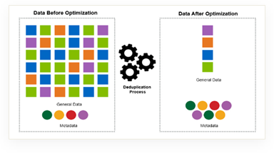
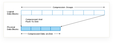
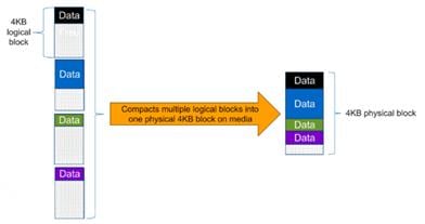
Note: Some applications such as Oracle and SQL have unique headers in each of their data blocks that prevent the blocks to be identified as duplicates. So, for such applications, enabling deduplication does not result in significant savings. So, deduplication is not recommended to be enabled for databases. However, NetApp data compression works very well with databases, and we strongly recommend enabling compression for databases. Table 2 lists some guidelines where compression, deduplication and/or inline Zero block deduplication can be used. These are guidelines, not rules; environment may have different performance requirements and specific use cases.
Table 2. Compression and Deduplication Guidelines
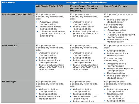
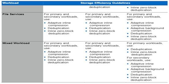
Table 3 lists the storage efficiency data reduction ratio ranges for different applications. A combination of synthetic datasets and real-world datasets has been used to determine the typical savings ratio range. The savings ratio range mentioned is only indicative.
Table 3. Typical Savings Ratios with ONTAP 9—Sample Savings Achieved with Internal and Customer Testing
| Typical Savings Ratios with ONTAP 9 |
|
| Workload [with deduplication, data compaction, adaptive compression and FlexClone volumes (where applicable) technologies] |
Ratio Range |
| Home directories |
1.5:1.-.2:1 |
| Software development |
2:1 - 10:1 |
| VDI Citrix Virtual Apps and Desktops full clone desktops (persistent) |
6:1 - 10:1 |
| VDI Citrix Virtual Apps and Desktops linked clone desktops (nonpersistent) |
5:1 - 7:1 |
| VDI Citrix Virtual Apps and Desktops Remote Desktop Server Hosted (RDSH) sessions Instant clone desktops (nonpersistent) |
6:1 - 10:1 |
| Virtual Servers (OS and Applications) |
2:1.-.4:1 |
| Oracle databases (with no database compression) |
2.1 - 4:1 |
| SQL 2014 databases (with no database compression) |
2.1 - 4:1 |
| Microsoft Exchange |
1.6:1 |
| Mongo DB |
1.3:1 - 1.5:1 |
| Recompressed data (such as video and image files, audio files, pdfs, and so on) |
No Savings |
NetApp Storage Virtual Machine (SVM)
An SVM is a logical abstraction that represents the set of physical resources of the cluster. This adds extra security and peace of mind to your VDI environment, giving you another place besides vCenter to apply HA, High Availability. Data volumes and network logical interfaces (LIFs) are created and assigned to an SVM and may reside on any node in the cluster to which the SVM has been given access. An SVM may own resources on multiple nodes concurrently, and those resources can be moved non-disruptively from one node to another. For example, a flexible volume can be non-disruptively moved to a new node and aggregate, or a data LIF can be transparently reassigned to a different physical network port. The SVM abstracts the cluster hardware, and it is not tied to any specific physical hardware.
An SVM can support multiple data protocols concurrently. Volumes within the SVM can be joined together to form a single NAS namespace, which makes all of an SVM's data available through a single share or mount point to create a VMware NFS datastore for your VDI desktop folders. SVMs also support block-based protocols, and LUNs can be created and exported by using iSCSI, FC, or FCoE. Any or all of these data protocols can be configured for use within a given SVM to support your VDI needs.
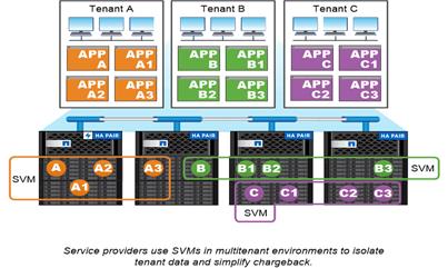
FlexClones
FlexClone technology references Snapshot metadata to create writable, point-in-time copies of a volume. Copies share data blocks with their parents, consuming no storage except what is required for metadata until changes are written to the copy. FlexClone files and FlexClone LUNs use identical technology, except that a backing Snapshot copy is not required.
Where traditional copies can take minutes or even hours to create, FlexClone software lets you copy even the largest datasets almost instantaneously. That makes it ideal for situations in which you need multiple copies of identical datasets (a virtual desktop deployment, for example) or temporary copies of a dataset (testing an application against a production dataset).
You can clone an existing FlexClone volume, clone a volume containing LUN clones, or clone mirror and vault data. You can split a FlexClone volume from its parent, in which case the copy is allocated its own storage.
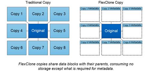
NetApp recommends implementing SAN boot for Cisco UCS servers in the FlexPod Datacenter solution. Doing so enables the ESXI host to be safely secured by the NetApp All Flash FAS storage system, providing better performance. In this design, the FC SAN boot is validated.
In FC SAN boot, each Cisco UCS server boots by connecting the NetApp All Flash FAS storage to the Cisco MDS switch. The 32G FC storage ports, in this example 1a and 1b, are connected to Cisco MDS switch. The FC LIFs are created on the physical ports and each FC LIF is uniquely identified by its target WWPN. The storage system target WWPNs can be zoned with the server initiator WWPNs in the Cisco MDS switches. The FC boot LUN is exposed to the servers through the FC LIF using the MDS switch; this enables only the authorized server to have access to the boot LUN.
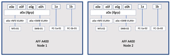
Unlike NAS network interfaces, the SAN network interfaces are not configured to fail over during a failure. Instead if a network interface becomes unavailable, the ESXI host chooses a new optimized path to an available network interface. ALUA is a standard supported by NetApp used to provide information about SCSI targets, which allows a host to identify the best path to the storage.
ONTAP 9.3 brought an innovation in scale-out NAS file systems: NetApp FlexGroup volumes, which plays a major role to give ONTAP the ability to be scaled nondisruptively out to 24 storage nodes while not degrading the performance of the VDI infrastructure.
With FlexGroup volumes, a storage administrator can easily provision a massive single namespace in a matter of seconds. FlexGroup volumes have virtually no capacity or file count constraints outside of the physical limits of hardware or the total volume limits of ONTAP. Limits are determined by the overall number of constituent member volumes that work in collaboration to dynamically balance load and space allocation evenly across all members. There is no required maintenance or management overhead with a FlexGroup volume. You simply create the FlexGroup volume and share it with your NAS clients. NetApp ONTAP does the rest.
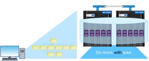
Storage QoS
Storage QoS (Quality of Service) can help you manage risks around meeting your performance objectives. You use Storage QoS to limit the throughput to workloads and to monitor workload performance. You can reactively limit workloads to address performance problems and you can pro-actively limit workloads to prevent performance problems.
A workload represents the input/output (I/O) operations to one of the following kinds of storage objects:
● FlexVol volumes
● LUNs
You assign a storage object to a policy group to control and monitor a workload. You can monitor workloads without controlling them.
Figure 21 illustrates an example environment before and after using Storage QoS. On the left, workloads compete for cluster resources to transmit I/O. These workloads get "best effort" performance, which means you have less performance predictability (for example, a workload might get such good performance that it negatively impacts other workloads). On the right are the same workloads assigned to policy groups. The policy groups enforce a maximum throughput limit.
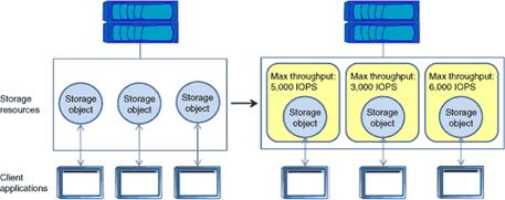
NetApp storage quality of service (QoS) works with both SAN and NAS storage, and it runs across the entire NetApp product line from entry to enterprise. Storage QoS offers significant benefits for all types of VDI environments. It lets you:
● Achieve greater levels of consolidation
● Set maximum and minimum limits on multiple VDI workloads that require separate service level agreements (SLAs)
● Add additional workloads with less risk of interference
● Make sure your customers get what they pay for, but not more
Adaptive QoS
Adaptive QoS automatically scales the policy group (A policy group defines the throughput ceiling for one or more workloads) value to workload (A workload represents the I/O operations for a storage object: a volume, file, qtree or LUN, or all the volumes, files, qtrees, or LUNs in an SVM) size, for the size of the workload changes. That is a significant advantage when you are managing hundreds or thousands of workloads in a VDI deployment. With Adaptive QoS, Ceiling and Floor limit can be set using allocated or used space. The QoS also address HA and Scaling as it will assist in both efforts to produce a non-disruptive change during VDI growth by maintaining the ratio of IOPS to TBs/GBs. To assist in managing your QOS, Active IQ unified manager will provide QOS suggestions based on historical performance and usage.
Three default adaptive QoS policy groups are available, as listed in Table 4. You can apply these policy groups directly to a volume.
Table 4. Available Default Adaptive QoS Policy Groups
| Default Policy Group |
Expected IOPS/TB |
Peak IOPS/TB |
Absolute Min IOPS |
| Extreme |
6,144 |
12,288 |
500 |
| Performance |
2,048 |
4,096 |
500 |
| Value |
128 |
512 |
75 |
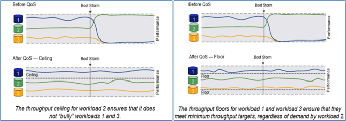
Security and Data Protection
Vscan
With Vscan you can use integrated antivirus functionality on NetApp storage systems to protect data from being compromised by viruses or other malicious code. NetApp virus scanning, called Vscan, combines best-in-class third-party antivirus software with ONTAP features that give you the flexibility you need to control which files get scanned and when.
Storage systems offload scanning operations to external servers hosting antivirus software from third-party vendors. The ONTAP Antivirus Connector, provided by NetApp and installed on the external server, handles communication between the storage system and the antivirus software.
You can use on-access scanning to check for viruses when clients open, read, rename, or close files over CIFS. File operation is suspended until the external server reports the scan status of the file. If the file has already been scanned, ONTAP allows the file operation. Otherwise, it requests a scan from the server.
You can use on-demand scanning to check files for viruses immediately or on a schedule. You might want to run scans only in off-peak hours, for example. The external server updates the scan status of the checked files, so that file-access latency for those files (assuming they have not been modified) is typically reduced when they are next accessed over CIFS. You can use on-demand scanning for any path in the SVM namespace, even for volumes that are exported only through NFS.
Typically, you enable both scanning modes on an SVM. In either mode, the antivirus software takes remedial action on infected files based on your settings in the software.
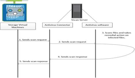
NetApp Volume Encryption (NVE) and NetApp Aggregate Encryption (NAE)
NetApp Volume Encryption is a software-based, data-at-rest encryption solution that is FIPS 140-2 compliant. NVE allows ONTAP to encrypt data for each volume for granularity. NAE, is an outgrowth of NVE; it allows ONTAP to encrypt data for each volume, and the volumes can share keys across the aggregate. NVE and NAE enable you to use storage efficiency features that would be lost with encryption at the application layer. For greater storage efficiency, you can use aggregate deduplication with NAE.
Here’s how the process works: The data leaves the disk encrypted, is sent to RAID, is decrypted by the CryptoMod, and is then sent up the rest of the stack. This process is illustrated in Figure 24.
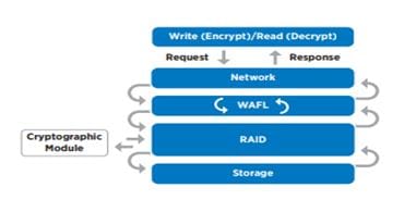
To view the latest security features for ONTAP 9, go to: Security Features in ONTAP 9 | NetApp.
ONTAP Rest API
ONTAP Rest API enables you to automate the deployment and administration of your ONTAP storage systems using one of several available options. The ONTAP REST API provides the foundation for all the various ONTAP automation technologies.
Beginning with ONTAP 9.6, ONTAP includes an expansive workflow-driven REST API that you can use to automate deployment and management of your storage. In addition, NetApp provides a Python client library, which makes it easier to write robust code, as well as support for ONTAP automation based on Ansible.
AutoSupport and Active IQ Digital Advisor
ONTAP offers artificial intelligence-driven system monitoring and reporting through a web portal and through a mobile app. The AutoSupport component of ONTAP sends telemetry that is analyzed by Active IQ Digital Advisor. Active IQ enables you to optimize your data infrastructure across your global hybrid cloud by delivering actionable predictive analytics and proactive support through a cloud-based portal and mobile app. Data-driven insights and recommendations from Active IQ are available to all NetApp customers with an active SupportEdge contract (features vary by product and support tier).
The following are some things you can do with Active IQ:
● Plan upgrades. Active IQ identifies issues in your environment that can be resolved by upgrading to a newer version of ONTAP and the Upgrade Advisor component helps you plan for a successful upgrade.
● View system wellness. Your Active IQ dashboard reports any issues with wellness and helps you correct those issues. Monitor system capacity to make sure you never run out of storage space.
● Manage performance. Active IQ shows system performance over a longer period than you can see in ONTAP System Manager. Identify configuration and system issues that are impacting your performance.
● Maximize efficiency. View storage efficiency metrics and identify ways to store more data in less space.
● View inventory and configuration. Active IQ displays complete inventory and software and hardware configuration information. View when service contracts are expiring to ensure you remain covered.
Security and Ransomware Protection
Ransomware is a type of malware that threatens to publish the victim's personal data or permanently block access to it unless a ransom is paid off. A ransomware attack can have direct and indirect impacts so it’s important to detect it as early as possible so that you can prevent its spread and avoid costly downtime.
NetApp storage administrators use local or remote login accounts to authenticate themselves to the cluster and storage VM. Role-Based Access Control (RBAC) determines the commands to which an administrator has access. In addition to RBAC, NetApp ONTAP supports multi-factor authentication (MFA) and multi-admin verification (MAV) to enhance the security of the storage system.
With NetApp ONTAP, you can use the security login create command to enhance security by requiring that administrators log in to an admin or data SVM with both an SSH public key and a user password. Beginning with ONTAP 9.12.1, you can use Yubikey hardware authentication devices for SSH client MFA using the FIDO2 (Fast IDentity Online) or Personal Identity Verification (PIV) authentication standards.
With ONTAP 9.11.1, you can use multi-admin verification (MAV) to ensure that certain operations, such as deleting volumes or Snapshot copies, can be executed only after approvals from designated administrators. This prevents compromised, malicious, or inexperienced administrators from making undesirable changes or deleting data.
Also, with ONTAP 9.10.1, the Autonomous Ransomware Protection (ARP) feature uses workload analysis in NAS (NFS and SMB) environments to proactively detect and warn about abnormal activity that might indicate a ransomware attack. While NetApp ONTAP includes features like FPolicy, Snapshot copies, SnapLock, and Active IQ Digital Advisor to help protect from ransomware, ARP utilizes machine-learning and simplifies the detection of and the recovery from a ransomware attack. ARP can detect the spread of most ransomware attacks after only a small number of files are encrypted, take action automatically to protect data, and alert users that a suspected attack is happening. When an attack is suspected, the system takes a volume Snapshot copy at that point in time and locks that copy. If the attack is confirmed later, the volume can be restored to this proactively taken snapshot to minimize the data loss.
For more information on MFA, MAV, and ransomware protection features, refer to the following:
● https://docs.netapp.com/us-en/ontap/authentication/setup-ssh-multifactor-authentication-task.html
● https://www.netapp.com/pdf.html?item=/media/17055-tr4647pdf.pdf
● https://docs.netapp.com/us-en/ontap/multi-admin-verify/
● https://docs.netapp.com/us-en/ontap/anti-ransomware/
VMware vSphere is a virtualization platform for holistically managing large collections of infrastructures (resources including CPUs, storage, and networking) as a seamless, versatile, and dynamic operating environment. Unlike traditional operating systems that manage an individual machine, VMware vSphere aggregates the infrastructure of an entire data center to create a single powerhouse with resources that can be allocated quickly and dynamically to any application in need.
VMware vSphere 8.0 U1 has several improvements and simplifications including, but not limited to:
● Fully featured vSphere Client (HTML5) client. The flash-based vSphere Web Client has been deprecated and is no longer available.
● Improved Distributed Resource Scheduler (DRS) – a very different approach that results in a much more granular optimization of resources.
● Assignable hardware – a new framework that was developed to extend support for vSphere features when you utilize hardware accelerators.
● vSphere Lifecycle Manager – a replacement for VMware Update Manager, bringing a suite of capabilities to make lifecycle operations better.
● Refactored vMotion – improved to support today’s workloads
For more information about VMware vSphere and its components, see: https://www.vmware.com/products/vsphere.html.
VMware vSphere vCenter
VMware vCenter Server provides unified management of all hosts and VMs from a single console and aggregates performance monitoring of clusters, hosts, and VMs. VMware vCenter Server gives administrators a deep insight into the status and configuration of compute clusters, hosts, VMs, storage, the guest OS, and other critical components of a virtual infrastructure. VMware vCenter manages the rich set of features available in a VMware vSphere environment.
Cisco Intersight Assist Device Connector for VMware vCenter and NetApp ONTAP
Cisco Intersight integrates with VMware vCenter and NetApp storage as follows:
● Cisco Intersight uses the device connector running within Cisco Intersight Assist virtual appliance to communicate with the VMware vCenter.
● Cisco Intersight uses the device connector running within a Cisco Intersight Assist virtual appliance to integrate with NetApp Active IQ Unified Manager. The NetApp AFF A400 should be added to NetApp Active IQ Unified Manager.
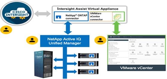
The device connector provides a secure way for connected targets to send information and receive control instructions from the Cisco Intersight portal using a secure internet connection. The integration brings the full value and simplicity of Cisco Intersight infrastructure management service to VMware hypervisor and ONTAP data storage environments.
Enterprise SAN and NAS workloads can benefit equally from the integrated management solution. The integration architecture enables FlexPod customers to use new management capabilities with no compromise in their existing VMware or ONTAP operations. IT users will be able to manage heterogeneous infrastructure from a centralized Cisco Intersight portal. At the same time, the IT staff can continue to use VMware vCenter and NetApp Active IQ Unified Manager for comprehensive analysis, diagnostics, and reporting of virtual and storage environments. The functionality provided through this integration is covered in the upcoming solution design section.
ONTAP Tools for VMware vSphere
NetApp ONTAP tools for VMware vSphere is a unified appliance that includes vSphere Storage Console (VSC),VASA Provider and SRA Provider. This vCenter web client plug-in that provides Context sensitive menu to provision traditional datastores and Virtual Volume (vVol) datastore.
ONTAP tools provides visibility into the NetApp storage environment from within the vSphere web client. VMware administrators can easily perform tasks that improve both server and storage efficiency while still using role-based access control to define the operations that administrators can perform. It includes enhanced REST APIs that provide vVols metrics for SAN storage systems using ONTAP 9.7 and later. So, NetApp OnCommand API Services is no longer required to get metrics for ONTAP systems 9.7 and later.
To download ONTAP tools for VMware vSphere, go to: https://mysupport.netapp.com/site/products/all/details/otv/downloads-tab.
NetApp NFS Plug-in for VMware VAAI
The NetApp NFS Plug-in for VMware vStorage APIs - Array Integration (VAAI) is a software library that integrates the VMware Virtual Disk Libraries that are installed on the ESXi host. The VMware VAAI package enables the offloading of certain tasks from the physical hosts to the storage array. Performing those tasks at the array level can reduce the workload on the ESXi hosts.
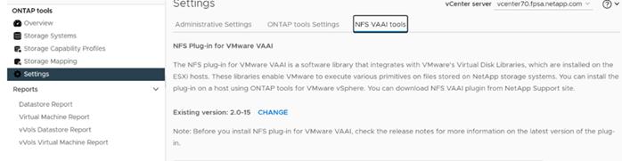
The copy offload feature and space reservation feature improve the performance of VSC operations. The NetApp NFS Plug-in for VAAI is not shipped with VSC, but you can install it by using VSC. You can download the plug-in installation package and obtain the instructions for installing the plug-in from the NetApp Support Site.
For more information about the NetApp VSC for VMware vSphere, see the NetApp Virtual Infrastructure Management Product Page.
NetApp XCP file analytics is host-based software to scan the file shares, collect and analyzes the data and provide insights into the file system. NetApp XCP file analytics works for both NetApp and non-NetApp systems and runs on Linux or Windows host. For more information, go to: http://docs.netapp.com/us-en/xcp/index.html
Architecture and Design Considerations for Desktop Virtualization
This chapter contains the following:
● Understanding Applications and Data
● Project Planning and Solution Sizing Sample Questions
● Citrix Virtual Apps and Desktops Design Fundamentals
There are many reasons to consider a virtual desktop solution such as an ever growing and diverse base of user devices, complexity in management of traditional desktops, security, and even Bring Your Own Device (BYOD) to work programs. The first step in designing a virtual desktop solution is to understand the user community and the type of tasks that are required to successfully execute their role. The following user classifications are provided:
● Knowledge Workers today do not just work in their offices all day – they attend meetings, visit branch offices, work from home, and even coffee shops. These anywhere workers expect access to all of their same applications and data wherever they are.
● External Contractors are increasingly part of your everyday business. They need access to certain portions of your applications and data, yet administrators still have little control over the devices they use and the locations they work from. Consequently, IT is stuck making trade-offs on the cost of providing these workers a device vs. the security risk of allowing them access from their own devices.
● Task Workers perform a set of well-defined tasks. These workers access a small set of applications and have limited requirements from their PCs. However, since these workers are interacting with your customers, partners, and employees, they have access to your most critical data.
● Mobile Workers need access to their virtual desktop from everywhere, regardless of their ability to connect to a network. In addition, these workers expect the ability to personalize their PCs, by installing their own applications and storing their own data, such as photos and music, on these devices.
● Shared Workstation users are often found in state-of-the-art University and business computer labs, conference rooms or training centers. Shared workstation environments have the constant requirement to re-provision desktops with the latest operating systems and applications for the needs of the organization change, tops the list.
After the user classifications have been identified and the business requirements for each user classification have been defined, it becomes essential to evaluate the types of virtual desktops that are needed based on user requirements. There are essentially five potential desktops environments for each user:
● Traditional PC: A traditional PC is what typically constitutes a desktop environment: a physical device with a locally installed operating system.
● Hosted Shared Desktop: A hosted, server-based desktop is a desktop where the user interacts through a delivery protocol. With hosted, server-based desktops, a single installed instance of a server operating system, such as Microsoft Windows Server 2022, is shared by multiple users simultaneously. Each user receives a desktop "session" and works in an isolated memory space. Remoted Desktop Server Hosted Server sessions: A hosted virtual desktop is a virtual desktop running on a virtualization layer (ESX). The user does not work with and sit in front of the desktop, but instead, the user interacts through a delivery protocol.
● Published Applications: Published applications run entirely on the Citrix Virtual Apps and Desktops Remote Desktop Server Hosted (RDSH) sessions, RDS server virtual machines, and the user interacts through a delivery protocol. With published applications, a single installed instance of an application, such as Microsoft Office, is shared by multiple users simultaneously. Each user receives an application "session" and works in an isolated memory space.
● Streamed Applications: Streamed desktops and applications run entirely on the user‘s local client device and are sent from a server on demand. The user interacts with the application or desktop directly, but the resources may only available while they are connected to the network.
● Local Virtual Desktop: A local virtual desktop is a desktop running entirely on the user‘s local device and continues to operate when disconnected from the network. In this case, the user’s local device is used as a primary type and is synchronized with the data center when the device is connected to the network.
For the purposes of the validation represented in this document, both Citrix Virtual Apps and Desktops Remote Desktop Server Hosted (RDSH) sessions and Windows 11 Virtual Desktops sessions were validated. Each section provides some fundamental design decisions for this environment.
Understanding Applications and Data
When the desktop user groups and sub-groups have been identified, the next task is to catalog group application and data requirements. This can be one of the most time-consuming processes in the VDI planning exercise but is essential for the VDI project’s success. If the applications and data are not identified and co-located, performance will be negatively affected.
The process of analyzing the variety of application and data pairs for an organization will likely be complicated by the inclusion cloud applications, for example, SalesForce.com. This application and data analysis is beyond the scope of this Cisco Validated Design but should not be omitted from the planning process. There are a variety of third-party tools available to assist organizations with this crucial exercise.
Project Planning and Solution Sizing Sample Questions
Now that user groups, their applications, and their data requirements are understood, some key project and solution sizing questions may be considered.
General project questions should be addressed at the outset, including:
● Has a VDI pilot plan been created based on the business analysis of the desktop groups, applications, and data?
● Is there infrastructure and budget in place to run the pilot program?
● Are the required skill sets to execute the VDI project available? Can we hire or contract for them?
● Do we have end user experience performance metrics identified for each desktop sub-group?
● How will we measure success or failure?
● What is the future implication of success or failure?
Below is a short, non-exhaustive list of sizing questions that should be addressed for each user sub-group:
● What is the desktop OS planned? Windows 11 or Windows 11?
● 32 bit or 64 bit desktop OS?
● How many virtual desktops will be deployed in the pilot? In production? All Windows 11?
● How much memory per target desktop group desktop?
● Are there any rich media, Flash, or graphics-intensive workloads?
● Are there any applications installed? What application delivery methods will be used, Installed, Streamed, Layered, Hosted, or Local?
● What is the OS planned for RDS Server Roles? Windows Server 2022 or Server 2022?
● What is the hypervisor for the solution?
● What is the storage configuration in the existing environment?
● Are there sufficient IOPS available for the write-intensive VDI workload?
● Will there be storage dedicated and tuned for VDI service?
● Is there a voice component to the desktop?
● Is anti-virus a part of the image?
● What is the SQL server version for the database? SQL server 2017 or 2022?
● Is user profile management (for example, non-roaming profile based) part of the solution?
● What is the fault tolerance, failover, disaster recovery plan?
● Are there additional desktop sub-group specific questions?
VMware vSphere has been identified for the hypervisor for both Citrix Virtual Apps and Desktops Remoted Server Desktop Hosted (RDSH) sessions and Windows 11 Virtual Desktops.
VMware vSphere comprises the management infrastructure or virtual center server software and the hypervisor software that virtualizes the hardware resources on the servers. It offers features like Distributed Resource Scheduler, vMotion, high availability, Storage vMotion, VMFS, and a multi-pathing storage layer. More information on vSphere can be obtained at the VMware website: http://www.vmware.com/products/datacentervirtualization/vsphere/overview.html.
Note: For this CVD, the hypervisor used was VMware ESXi 8.0 U1.
When utilizing Cisco UCS Server technology, it is recommended to configure Boot from SAN and store the boot partitions on remote storage, this enabled architects and administrators to take full advantage of the stateless nature of service profiles for hardware flexibility across lifecycle management of server hardware generational changes, Operating Systems/Hypervisors, and overall portability of server identity. Boot from SAN also removes the need to populate local server storage creating more administrative overhead.
NetApp AFF Storage Considerations
Note: Make sure each NetApp AFF Controller is connected to BOTH storage fabrics (A/B).
Within NetApp, the best practice is to map Hosts to iGroups and then iGroups to LUNs, this ensures same LUN ID to all hosts and allows for simplified management of ESXi Clusters across multiple nodes.
10/25/40/100 Gbe connectivity support – while both 10 and 25 Gbe is provided through 2 onboard NICs on each AFF controller, if more interfaces are required or if 40Gbe connectivity is also required, then make sure to provision for additional NICs have been included in the original AFF BOM.
16/32Gb Fiber Channel supports the NetApp Storage up to 32Gb FC support on the latest AFF A400 series arrays. Always make sure the correct number of HBAs and the speed of SFPs are included in the original AFF BOM.
Oversubscription
To reduce the impact of an outage or maintenance scheduled downtime it Is good practice when designing fabrics to provide oversubscription of bandwidth, this enables a similar performance profile during component failure and protects workloads from being impacted by a reduced number of paths during a component failure or maintenance event. Oversubscription can be achieved by increasing the number of physically cabled connections between storage and compute. These connections can be utilized to deliver performance and reduced latency to the underlying workloads running on the solution.
When configuring your SAN, it’s important to remember that the more hops you have, the more latency you will see. For best performance, the ideal topology is a “Flat Fabric” where the AFF is only one hop away from any applications being hosted on it.
VMware Virtual Volumes Considerations
vCenters that are in Enhanced Linked Mode will each be able to communicate with the same AFF, however vCenters that are not in Enhanced Linked Mode must use CA-Signed Certificates using the same AFF. If multiple vCenters need to use the same AFF for vVols, they should be configured in Enhanced Linked Mode.
There are some AFF limits on Volume Connections per Host, Volume Count, and Snapshot Count. For more information about NetApp AFF limits review the following: https://hwu.NetApp.com/Controller/Index
When a Storage Policy is applied to a vVol VM, the volumes associated with that VM are added to the designated protection group when applying the policy to the VM. If replication is part of the policy, be mindful of the amount of VMs using that storage policy and replication group. A large amount of VMs with a high change rate could cause replication to miss its schedule due to increased replication bandwidth and time needed to complete the scheduled snapshot. NetApp Storage recommends vVol VMs that have Storage Policies applied be balanced between protection groups.
Citrix Virtual Apps and Desktops Design Fundamentals
An ever growing and diverse base of user devices, complexity in management of traditional desktops, security, and even Bring Your Own (BYO) device to work programs are prime reasons for moving to a virtual desktop solution.
Citrix Virtual Apps and Desktops 7 integrates Hosted Shared and VDI desktop virtualization technologies into a unified architecture that enables a scalable, simple, efficient, and manageable solution for delivering Windows applications and desktops as a service.
You can select applications from an easy-to-use “store” that is accessible from tablets, smartphones, PCs, Macs, and thin clients. Virtual Apps and Desktops delivers a native touch-optimized experience with HDX high-definition performance, even over mobile networks.
Collections of identical virtual machines or physical computers are managed as a single entity called a Machine Catalog. In this CVD, virtual machine provisioning relies on Citrix Provisioning Services and Machine Creation Services to make sure that the machines in the catalog are consistent. In this CVD, machines in the Machine Catalog are configured to run either a Multi-session OS VDA (Windows Server OS) or a Single-session OS VDA (Windows Desktop OS).
To deliver desktops and applications to users, you create a Machine Catalog and then allocate machines from the catalog to users by creating Delivery Groups. Delivery Groups provide desktops, applications, or a combination of desktops and applications to users. Creating a Delivery Group is a flexible way of allocating machines and applications to users. In a Delivery Group, you can:
● Use machines from multiple catalogs
● Allocate a user to multiple machines
● Allocate multiple users to one machine
As part of the creation process, you specify the following Delivery Group properties:
● Users, groups, and applications allocated to Delivery Groups
● Desktop settings to match users' needs
● Desktop power management options
Figure 27 illustrates how users access desktops and applications through machine catalogs and delivery groups.
Citrix Virtual Apps and Desktops 7 can be deployed with or without Citrix Provisioning Services (PVS). The advantage of using Citrix PVS is that it allows virtual machines to be provisioned and re-provisioned in real-time from a single shared-disk image. In this way administrators can completely eliminate the need to manage and patch individual systems and reduce the number of disk images that they manage, even as the number of machines continues to grow, simultaneously providing the efficiencies of a centralized management with the benefits of distributed processing.
The Provisioning Services solution’s infrastructure is based on software-streaming technology. After installing and configuring Provisioning Services components, a single shared disk image (vDisk) is created from a device’s hard drive by taking a snapshot of the OS and application image, and then storing that image as a vDisk file on the network. A device that is used during the vDisk creation process is the Master target device. Devices or virtual machines that use the created vDisks are called target devices.
When a target device is turned on, it is set to boot from the network and to communicate with a Provisioning Server. Unlike thin-client technology, processing takes place on the target device.
The target device downloads the boot file from a Provisioning Server (Step 2) and boots. Based on the boot configuration settings, the appropriate vDisk is mounted on the Provisioning Server (Step 3). The vDisk software is then streamed to the target device as needed, appearing as a regular hard drive to the system.
Instead of immediately pulling all the vDisk contents down to the target device (as with traditional imaging solutions), the data is brought across the network in real-time as needed. This approach allows a target device to get a completely new operating system and set of software in the time it takes to reboot. This approach dramatically decreases the amount of network bandwidth required and making it possible to support a larger number of target devices on a network without impacting performance
Citrix PVS can create desktops as Pooled or Private:
● Pooled Desktop: A pooled virtual desktop uses Citrix PVS to stream a standard desktop image to multiple desktop instances upon boot.
● Private Desktop: A private desktop is a single desktop assigned to one distinct user.
● The alternative to Citrix Provisioning Services for pooled desktop deployments is Citrix Machine Creation Services (MCS), which is integrated with the Virtual Apps and Desktops Studio console.
Locating the PVS Write Cache
When considering a PVS deployment, there are some design decisions that need to be made regarding the write cache for the target devices that leverage provisioning services. The write cache is a cache of all data that the target device has written. If data is written to the PVS vDisk in a caching mode, the data is not written back to the base vDisk. Instead, it is written to a write cache file in one of the following locations:
● Cache in device RAM. Write cache can exist as a temporary file in the target device’s RAM. This provides the fastest method of disk access since memory access is always faster than disk access.
● Cache in device RAM with overflow on hard disk. This method uses VHDX differencing format and is only available for Windows 11 and Server 2008 R2 and later. When RAM is zero, the target device write cache is only written to the local disk. When RAM is not zero, the target device write cache is written to RAM first. When RAM is full, the least recently used block of data is written to the local differencing disk to accommodate newer data on RAM. The amount of RAM specified is the non-paged kernel memory that the target device will consume.
● Cache on a server. Write cache can exist as a temporary file on a Provisioning Server. In this configuration, all writes are handled by the Provisioning Server, which can increase disk I/O and network traffic. For additional security, the Provisioning Server can be configured to encrypt write cache files. Since the write-cache file persists on the hard drive between reboots, encrypted data provides data protection in the event a hard drive is stolen.
● Cache on server persisted. This cache option allows for the saved changes between reboots. Using this option, a rebooted target device is able to retrieve changes made from previous sessions that differ from the read only vDisk image. If a vDisk is set to this method of caching, each target device that accesses the vDisk automatically has a device-specific, writable disk file created. Any changes made to the vDisk image are written to that file, which is not automatically deleted upon shutdown.
Note: In this CVD, Provisioning Server 2022 was used to manage Pooled/Non-Persistent Single-session OS Machines with “Cache in device RAM with Overflow on Hard Disk” for each virtual machine. This design enables good scalability to many thousands of desktops. Provisioning Server 2022 was used for Active Directory machine account creation and management as well as for streaming the shared disk to the hypervisor hosts.
Example Citrix Virtual Apps and Desktops Deployments
Two examples of typical Virtual Apps and Desktops deployments are as follows:
● A distributed components configuration
● A multiple site configuration
Distributed Components Configuration
You can distribute the components of your deployment among a greater number of servers or provide greater scalability and failover by increasing the number of controllers in your site. You can install management consoles on separate computers to manage the deployment remotely. A distributed deployment is necessary for an infrastructure based on remote access through NetScaler Gateway (formerly called Access Gateway).
Figure 29 shows an example of a distributed components configuration. A simplified version of this configuration is often deployed for an initial proof-of-concept (POC) deployment. The CVD described in this document deploys Citrix Virtual Apps and Desktops in a configuration that resembles this distributed component configuration shown.
If you have multiple regional sites, you can use Citrix NetScaler to direct user connections to the most appropriate site and StoreFront to deliver desktops and applications to users.
Figure 30 depicts multiple sites; a site was created in two data centers. Having two sites globally, rather than just one, minimizes the amount of unnecessary WAN traffic.
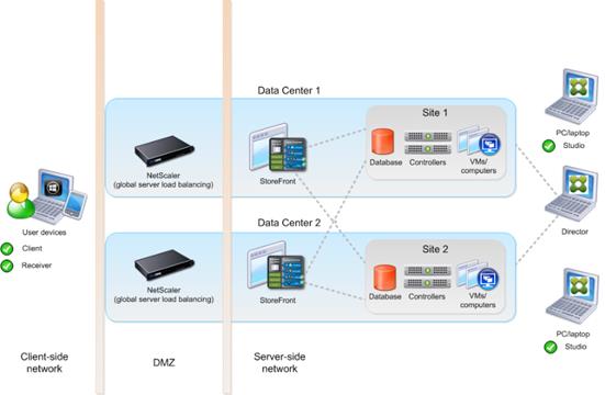
You can use StoreFront to aggregate resources from multiple sites to provide users with a single point of access with NetScaler. A separate Studio console is required to manage each site; sites cannot be managed as a single entity. You can use Director to support users across sites.
Citrix NetScaler accelerates application performance, load balances servers, increases security, and optimizes the user experience. In this example, two NetScalers are used to provide a high availability configuration. The NetScalers are configured for Global Server Load Balancing and positioned in the DMZ to provide a multi-site, fault-tolerant solution.
Note: The CVD was done based on single site and did not use NetScaler for its infrastructure and testing.
Easily deliver the Citrix portfolio of products as a service. Citrix Cloud services simplify the delivery and management of Citrix technologies extending existing on-premises software deployments and creating hybrid workspace services.
● Fast: Deploy apps and desktops, or complete secure digital workspaces in hours, not weeks.
● Adaptable: Choose to deploy on any cloud or virtual infrastructure — or a hybrid of both.
● Secure: Keep all proprietary information for your apps, desktops, and data under your control.
● Simple: Implement a fully-integrated Citrix portfolio through a single-management plane to simplify administration
Designing a Virtual Apps and Desktops Environment for Different Workloads
With Citrix Virtual Apps and Desktops, the method you choose to provide applications or desktops to users depends on the types of applications and desktops you are hosting and available system resources, as well as the types of users and user experience you want to provide.
| Desktop Type |
User Experience |
| Server OS machines |
You want: Inexpensive server-based delivery to minimize the cost of delivering applications to a large number of users, while providing a secure, high-definition user experience. Your users: Perform well-defined tasks and do not require personalization or offline access to applications. Users may include task workers such as call center operators and retail workers, or users that share workstations. Application types: Any application. |
| Desktop OS machines |
You want: A client-based application delivery solution that is secure, provides centralized management, and supports a large number of users per host server (or hypervisor), while providing users with applications that display seamlessly in high-definition. Your users: Are internal, external contractors, third-party collaborators, and other provisional team members. Users do not require off-line access to hosted applications. Application types: Applications that might not work well with other applications or might interact with the operating system, such as .NET framework. These types of applications are ideal for hosting on virtual machines. Applications running on older operating systems such as Windows XP or Windows Vista, and older architectures, such as 32-bit or 16-bit. By isolating each application on its own virtual machine, if one machine fails, it does not impact other users. |
| Remote PC Access |
You want: Employees with secure remote access to a physical computer without using a VPN. For example, the user may be accessing their physical desktop PC from home or through a public WIFI hotspot. Depending upon the location, you may want to restrict the ability to print or copy and paste outside of the desktop. This method enables BYO device support without migrating desktop images into the data center. Your users: Employees or contractors that have the option to work from home but need access to specific software or data on their corporate desktops to perform their jobs remotely. Host: The same as Desktop OS machines. Application types: Applications that are delivered from an office computer and display seamlessly in high definition on the remote user's device. |
For this Cisco Validated Design, the following designs are included:
● Single-session OS Solution:
◦ MCS: 2000 Windows 11 Virtual desktops random pooled were configured and tested
◦ PVS: 2000 Windows 11 Virtual desktops random pooled were configured and tested
● Multi-session OS Solution:
◦ RDS: 2500 Windows Server 2022 random pooled desktops were configured and tested
Deployment Hardware and Software
This chapter contains the following:
The architecture deployed is highly modular. While each environment might vary in its exact configuration, the reference architecture contained in this document once built, can easily be scaled as requirements, and demands change. This includes scaling both up (adding additional resources within a Cisco UCS Domain) and out (adding additional Cisco UCS Domains and NetApp storage).
The FlexPod Datacenter solution includes Cisco networking, Cisco UCS and NetApp AFF A400, which efficiently fit into a single data center rack, including the access layer network switches.
This CVD details the deployment of up to 2500 Multi-session OS, 2000 Single-session OS VDI users featuring the following software:
● VMware vSphere ESXi 8.0 U1 Hypervisor
● Microsoft SQL Server 2022
● Microsoft Windows Server 2022 and Windows 11 64-bit virtual machine Operating Systems
● Citrix Virtual Apps and Desktops 2203 LTSR
● Citrix Provisioning Server 2203 LTSR
● FSLogix 2210 (2.9.8361.52326)
● Citrix StoreFront 2203 LTSR
● NetApp ONTAP Tools for VMware vSphere 9.12
● NetApp ONTAP 9.13.1P3
FlexPod with Cisco UCS M7 servers, Citrix Virtual Apps and Desktops Remote Desktop Server Hosted (RDSH) sessions and Windows 11 virtual desktops on vSphere 8.0 U1 delivers a Virtual Desktop Infrastructure that is redundant, using the best practices of Cisco and NetApp Storage. The solution includes VMware vSphere 8.0 U1 hypervisor installed on the Cisco UCS M7 Compute Node Server configured for stateless compute design using boot from SAN. NetApp Storage AFF A400 provides the storage infrastructure required for setting up the VDI workload. Cisco Intersight is utilized to configure and manage the Cisco UCS infrastructure with Cisco Intersight providing lifecycle management capabilities. The solution requirements and design details are covered in this section.
FlexPod VDI with Cisco UCS X210c M7servers is an NFS-based storage access design. NetApp Storage AFF and Cisco UCS are connected through Cisco Nexus switches and storage access utilizes the NFS network. For VDI IP based file share storage access NetApp Storage AFF Cisco UCS are connected through Cisco Nexus N9K-C93180YC-FX3S switches. The physical connectivity details are explained below.
Figure 31 details the physical hardware and cabling deployed to enable this solution:
● 2 Cisco Nexus N9K-C93180YC-FX3S Switches in NX-OS Mode.
● 2 Cisco MDS 9132T Switches for Fiber Channel traffic
● 8 Cisco UCS X210c M7Compute Nodes with Intel Xeon 6448H 2.40GHz 32-core processors, 2TB 4400MHz RAM, and one Cisco UCS VIC 15231 card, providing N+1 server fault tolerance.
● NetApp AFF A400 Storage System with dual redundant controllers, 2x disk shelves, and 48 x 1.75 TB solid-state NVMe drives providing storage and NVME/NFS/CIFS connectivity.
Note: The common services and LoginVSI Test infrastructure are not a part of the physical topology of this solution.
Table 5 lists the software versions of the primary products installed in the environment.
Table 5. Software and Firmware Versions
| Vendor |
Product / Component |
Version / Build / Code |
| Cisco |
UCS Component Firmware |
5.2(0.230041) bundle release |
| Cisco |
Intersight |
5.2(0.230041) bundle release |
| Cisco |
UCS X210C M7Compute Nodes |
5.2(0.230041) bundle release |
| Cisco |
VIC 15231 |
5.2(0.230041) bundle release |
| Cisco |
Cisco Nexus N9K-C93180YC-FX3S |
9.3(7a) |
| NetApp |
AFF A400 |
ONTAP 9.13.1P3 |
| NetApp |
ONTAP Tools for VMWare vSphere |
9.12 |
| NetApp |
NetApp NFS Plug-in for VMWare VAAI |
2.0.1 |
| VMware |
vCenter Server Appliance |
8.0 |
| VMware |
vSphere 8.0 U1 |
8.0.1, 21813344 |
| VMware |
Tools |
11.2.5.17337674 |
| Citrix |
Broker |
2203 LTSR |
| Citrix |
Agent |
2203 LTSR |
| Citrix |
Provisioning Server |
2203 LTSR |
The logical architecture of the validated solution which is designed to support up to 2500 users on a single chassis containing eight Cisco UCS X210c M7Compute Node Servers, with physical redundancy for the Compute Node servers for each workload type is illustrated in Figure 32.
Two VMware Clusters in one vCenter data center were utilized to support the solution and testing environment:
● VDI Cluster FlexPod Data Center with Cisco UCS
◦ Infrastructure: Infra VMs (vCenter, Active Directory, DNS, DHCP, SQL Server, VMware and Desktops Controllers, Provisioning Servers, and NetApp ONTAP Tools for VMware vSphere, Active IQ Unified Manager, VMs, and so on)
◦ VDI Workload VMs (Windows Server 2022 streamed with Citrix Virtual Apps and Desktops, Windows 11 Streamed with Citrix Virtual Apps and Desktops Windows 11 Instant Clones and Persistent desktops)
● VSI Launchers and Launcher Cluster
For example, the cluster(s) configured for running LoginVSI workload for measuring VDI End User Experience is LVS-Launcher-CLSTR: (The Login VSI infrastructure cluster consists of Login VSI data shares, LVSI Web Servers and LVSI Management Control VMs and so on. were connected using the same set of switches and vCenter instance but was hosted on separate storage. LVS-Launcher-CLSTR configured and used for the purpose of testing LoginVSI End User Experience for VDI multi session users and VDI Windows 11 users.
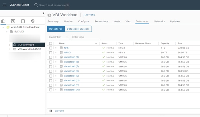
The Citrix Virtual Apps and Desktops solution described in this document provides details for configuring a fully redundant, highly-available configuration. Configuration guidelines are provided that refer to which redundant component is being configured with each step, whether that be A or B. For example, Nexus A and Nexus B identify the pair of Cisco Nexus switches that are configured. The Cisco UCS Fabric Interconnects are configured similarly.
This document is intended to allow you to configure the Citrix Virtual Apps and Desktops 2203 LTSR environment as a stand-alone solution.
The VLAN configuration recommended for the environment includes a total of six VLANs as listed in Table 6.
Table 6. VLANs Configured in this Study
| VLAN Name |
VLAN ID |
VLAN Purpose |
| Default |
1 |
Native VLAN |
| In-Band-Mgmt |
30 |
In-Band management interfaces |
| Infra-Mgmt |
31 |
Infrastructure Virtual Machines |
| CIFS-VLAN |
32 |
CIFS Storage access |
| NFS- VLAN |
33 |
VLAN for NFS storage traffic |
| VCC/VM-Network |
34 |
RDSH, VDI Persistent and Non-Persistent |
| vMotion |
35 |
vMotion for DRS and migration |
| OOB-Mgmt |
132 |
Out-of-Band management interfaces |
This chapter contains the following:
● Network Switch Configuration
● FlexPod Cisco Nexus Switch Configuration
The following sections detail the physical connectivity configuration of the FlexPod VMware VDI environment.
The information provided in this section is a reference for cabling the physical equipment in this Cisco Validated Design environment. To simplify cabling requirements, the tables include both local and remote device and port locations.
The tables in this section contain the details for the prescribed and supported configuration of the NetApp Storage AFF A400 storage array to the Cisco UCS 6536 Fabric Interconnects through Cisco Nexus Switches.
Note: This document assumes that out-of-band management ports are plugged into an existing management infrastructure at the deployment site. These interfaces will be used in various configuration steps.
IMPORTANT! Be sure to follow the cabling directions in this section. Failure to do so will result in unnecessary changes to the deployment since specific port locations are mentioned.
Figure 34 details the cable connections used in the validation lab for FlexPod topology based on the Cisco UCS 6536 fabric interconnect. Also, 40Gb links connect the Cisco UCS Fabric Interconnects to the Cisco Nexus Switches and the NetApp AFF A400 controllers to the Cisco Nexus Switches. Additional 1Gb management connections will be needed for an out-of-band network switch that sits apart from the FlexPod infrastructure. Each Cisco UCS fabric interconnect and Cisco Nexus switch is connected to the out-of-band network switch, and each All Flash Array controller has a connection to the out-of-band network switch. Layer 3 network connectivity is required between the Out-of-Band (OOB) and In-Band (IB) Management Subnets.
The architecture is divided into three distinct layers:
1. Cisco UCS Compute Platform
2. Network Access layer and LAN
3. Storage Access to the NetApp AFF A400
Table 7. Cisco Nexus N9K-C93180YC-FX3S-A Cabling Information
| Local Device |
Local Port |
Connection |
Remote Device |
Remote Port |
| Cisco Nexus N9K-C93180YC-FX3S A |
Eth1/17 |
25GbE |
NetApp Controller 2 |
e0e Controller 1 |
| Eth1/18 |
25GbE |
NetApp Controller 2 |
e0f Controller 1 |
|
| Eth1/19 |
25GbE |
NetApp Controller 1 |
e0e Controller 2 |
|
| Eth1/20 |
25GbE |
NetApp Controller 1 |
e0f Controller 2 |
|
| Eth1/53 |
100GbE |
Cisco UCS Nexus Peer-Link |
P0 1/21 |
|
| Eth1/54 |
100GbE |
Cisco UCS Nexus Peer-Link |
P0 1/23 |
|
| Eth1/49 |
100GbE |
Cisco UCS fabric interconnect A |
P0 1/21 |
|
| Eth1/50 |
100GbE |
Cisco UCS fabric interconnect B |
P0 1/23 |
|
| MGMT0 |
GbE |
GbE management switch |
Any |
|
|
|
|
|
|
|
|
|
|
|
|
Note: For devices requiring GbE connectivity, use the GbE Copper SFP+s (GLC-T=).
Table 8. Cisco Nexus N9K-C93180YC-FX3S-B Cabling Information
| Local Device |
Local Port |
Connection |
Remote Device |
Remote Port |
| Cisco Nexus N9K-C93180YC-FX3S B |
Eth1/17 |
25GbE |
NetApp Controller 1 |
e0h Controller 1 |
| Eth1/18 |
25GbE |
NetApp Controller 1 |
e0g Controller 1 |
|
| Eth1/19 |
25GbE |
NetApp Controller 2 |
e0g Controller 2 |
|
| Eth1/20 |
25GbE |
NetApp Controller 2 |
e0h Controller 2 |
|
| Eth1/53 |
100GbE |
Cisco UCS Nexus Peer-Link |
P0 1/21 |
|
| Eth1/54 |
100GbE |
Cisco UCS Nexus Peer-Link |
P0 1/23 |
|
| Eth1/49 |
100GbE |
Cisco UCS fabric interconnect A |
P0 1/21 |
|
| Eth1/50 |
100GbE |
Cisco UCS fabric interconnect B |
P0 1/23 |
|
| MGMT0 |
GbE |
GbE management switch |
Any |
|
|
|
|
|
|
|
|
|
|
|
|
Table 9. NetApp Controller-1 Cabling Information
| Local Device |
Local Port |
Connection |
Remote Device |
Remote Port |
| NetApp AFF400 Node 1
|
e0M |
1GbE |
1GbE management switch |
Any |
| e0s |
GbE |
GbE management switch |
Any |
|
| e0h |
25GbE |
Data Ports |
N9K-A Eth1/17 |
|
| e0g |
25GbE |
Data Ports |
N9K-A Eth1/18 |
|
|
|
e0e |
25GbE |
Data Ports |
N9K-B Eth1/17 |
|
|
e0f |
25GbE |
Data Ports |
N9K-B Eth/1/18 |
Note: When the term e0M is used, the physical Ethernet port to which the table is referring is the port indicated by a wrench icon on the rear of the chassis.
Table 10. NetApp Controller 2 Cabling Information
| Local Device |
Local Port |
Connection |
Remote Device |
Remote Port |
| NetApp AFF400 Node 2
|
e0M |
1GbE |
1GbE management switch |
Any |
| e0s |
GbE |
GbE management switch |
Any |
|
| e0e |
25GbE |
Data Ports |
N9K-A Eth1/19 |
|
| e0f |
25GbE |
Data Ports |
N9K-A Eth1/20 |
|
|
|
e0g |
25GbE |
Data Ports |
N9K-B Eth1/19 |
|
|
e0h |
25GbE |
Data Ports |
N9K-B Eth/1/20 |
Table 11. Cisco UCS Fabric Interconnect A Cabling Information
| Local Device |
Local Port |
Connection |
Remote Device |
Remote Port |
| Cisco UCS Fabric Interconnect A |
Eth1/41 |
25GbE |
Cisco Nexus N9K-C93180YC-FX3S B |
Eth1/41 |
| Eth1/29 |
100GbE |
Cisco Nexus N9K-C93180YC-FX3S A |
Eth1/49 |
|
| Eth1/30 |
100GbE |
Cisco Nexus N9K-C93180YC-FX3S B |
Eth1/49 |
|
| MGMT0 |
GbE |
GbE Management switch |
|
|
| L1 |
GbE |
Cisco UCS fabric interconnect B |
L1 |
|
| L2 |
GbE |
Cisco UCS fabric interconnect B |
L2 |
Table 12. Cisco UCS Fabric Interconnect B Cabling Information
| Local Device |
Local Port |
Connection |
Remote Device |
Remote Port |
| Cisco UCS Fabric Interconnect B |
Eth1/29 |
25GbE |
Cisco Nexus N9K-C93180YC-FX3S A |
Eth1/50 |
| Eth1/30 |
25GbE |
Cisco Nexus N9K-C93180YC-FX3S B |
Eth1/50 |
|
| MGMT0 |
GbE |
GbE management switch |
Any |
|
| L1 |
GbE |
Cisco UCS fabric interconnect A |
L1 |
|
| L2 |
GbE |
Cisco UCS fabric interconnect A |
L2 |
This section contains the following procedures:
● Set Up Initial Configuration on Cisco Nexus A
● Set Up Initial Configuration on Cisco Nexus B
This section provides a detailed procedure for configuring the Cisco Nexus N9K-C93180YC-FX3S switches for use in a FlexPod environment. The Cisco Nexus N9K-C93180YC-FX3S will be used LAN switching in this solution.
IMPORTANT! Follow these steps precisely because failure to do so could result in an improper configuration.
Follow the physical connectivity guidelines for FlexPod as explained in section Solution Cabling.
The following procedures describe how to configure the Cisco Nexus switches for use in a base FlexPod environment. This procedure assumes the use of Cisco Nexus 9000 9.3(7a), the Cisco suggested Nexus switch release at the time of this validation.
The following procedure includes the setup of NTP distribution on both the mgmt0 port and the in-band management VLAN. The interface-vlan feature and ntp commands are used to set this up. This procedure also assumes that the default VRF is used to route the in-band management VLAN.
Note: In this validation, port speed and duplex are hard set at both ends of every 100GE connection.
Procedure 1. Set Up Initial Configuration on Cisco Nexus A
Set up the initial configuration for the Cisco Nexus A switch on <nexus-A-hostname>
Step 1. On initial boot and connection to the serial or console port of the switch, the NX-OS setup should automatically start and attempt to enter Power on Auto Provisioning.
Abort Power On Auto Provisioning [yes - continue with normal setup, skip - bypass password and basic configuration, no - continue with Power On Auto Provisioning] (yes/skip/no)[no]: yes
Disabling POAP.......Disabling POAP
poap: Rolling back, please wait... (This may take 5-15 minutes)
---- System Admin Account Setup ----
Do you want to enforce secure password standard (yes/no) [y]: Enter
Enter the password for "admin": <password>
Confirm the password for "admin": <password>
Would you like to enter the basic configuration dialog (yes/no): yes
Create another login account (yes/no) [n]: Enter
Configure read-only SNMP community string (yes/no) [n]: Enter
Configure read-write SNMP community string (yes/no) [n]: Enter
Enter the switch name: <nexus-A-hostname>
Continue with Out-of-band (mgmt0) management configuration? (yes/no) [y]: Enter
Mgmt0 IPv4 address: <nexus-A-mgmt0-ip>
Mgmt0 IPv4 netmask: <nexus-A-mgmt0-netmask>
Configure the default gateway? (yes/no) [y]: Enter
IPv4 address of the default gateway: <nexus-A-mgmt0-gw>
Configure advanced IP options? (yes/no) [n]: Enter
Enable the telnet service? (yes/no) [n]: Enter
Enable the ssh service? (yes/no) [y]: Enter
Type of ssh key you would like to generate (dsa/rsa) [rsa]: Enter
Number of rsa key bits <1024-2048> [1024]: Enter
Configure the ntp server? (yes/no) [n]: Enter
Configure default interface layer (L3/L2) [L2]: Enter
Configure default switchport interface state (shut/noshut) [noshut]: shut
Enter basic FC configurations (yes/no) [n]: yes
Configure CoPP system profile (strict/moderate/lenient/dense) [strict]: Enter
Would you like to edit the configuration? (yes/no) [n]: Enter
Step 2. Review the configuration summary before enabling the configuration.
Use this configuration and save it? (yes/no) [y]: Enter
Procedure 2. Set Up Initial Configuration on Cisco Nexus B
Set up the initial configuration for the Cisco Nexus B switch on <nexus-B-hostname>.
Step 1. On initial boot and connection to the serial or console port of the switch, the NX-OS setup should automatically start and attempt to enter Power on Auto Provisioning.
Abort Power On Auto Provisioning [yes - continue with normal setup, skip - bypass password and basic configuration, no - continue with Power On Auto Provisioning] (yes/skip/no)[no]: yes
Disabling POAP.......Disabling POAP
poap: Rolling back, please wait... (This may take 5-15 minutes)
---- System Admin Account Setup ----
Do you want to enforce secure password standard (yes/no) [y]: Enter
Enter the password for "admin": <password>
Confirm the password for "admin": <password>
Would you like to enter the basic configuration dialog (yes/no): yes
Create another login account (yes/no) [n]: Enter
Configure read-only SNMP community string (yes/no) [n]: Enter
Configure read-write SNMP community string (yes/no) [n]: Enter
Enter the switch name: <nexus-B-hostname>
Continue with Out-of-band (mgmt0) management configuration? (yes/no) [y]: Enter
Mgmt0 IPv4 address: <nexus-B-mgmt0-ip>
Mgmt0 IPv4 netmask: <nexus-B-mgmt0-netmask>
Configure the default gateway? (yes/no) [y]: Enter
IPv4 address of the default gateway: <nexus-B-mgmt0-gw>
Configure advanced IP options? (yes/no) [n]: Enter
Enable the telnet service? (yes/no) [n]: Enter
Enable the ssh service? (yes/no) [y]: Enter
Type of ssh key you would like to generate (dsa/rsa) [rsa]: Enter
Number of rsa key bits <1024-2048> [1024]: Enter
Configure the ntp server? (yes/no) [n]: Enter
Configure default interface layer (L3/L2) [L2]: Enter
Configure default switchport interface state (shut/noshut) [noshut]: shut
Enter basic FC configurations (yes/no) [n]: yes
Configure CoPP system profile (strict/moderate/lenient/dense) [strict]: Enter
Would you like to edit the configuration? (yes/no) [n]: Enter
Step 2. Review the configuration summary before enabling the configuration.
Use this configuration and save it? (yes/no) [y]: Enter
FlexPod Cisco Nexus Switch Configuration
This section contains the following procedures:
● Enable Features on Cisco Nexus A and Cisco Nexus B
● Set Global Configurations on Cisco Nexus A and Cisco Nexus B
● Create VLANs on Cisco Nexus A and Cisco Nexus B
● Add NTP Distribution Interface on Cisco Nexus A
● Add NTP Distribution Interface on Cisco Nexus B
● Create Port Channels on Cisco Nexus A and Cisco Nexus B
● Configure Port Channel Parameters on Cisco Nexus A and Cisco Nexus B
● Configure Virtual Port Channels on Cisco Nexus A
● Configure Virtual Port Channels on Cisco Nexus B
Procedure 1. Enable Features on Cisco Nexus A and Cisco Nexus B
SAN switching requires both the SAN_ENTERPRISE_PKG and FC_PORT_ACTIVATION_PKG licenses. Please ensure these licenses are installed on each Cisco Nexus N9K-C93180YC-FX3S switch.
Step 1. Log in as admin.
Step 2. Since basic FC configurations were entered in the setup script, feature-set fcoe has been automatically installed and enabled. Run the following commands:
config t
feature udld
feature interface-vlan
feature lacp
feature vpc
feature lldp
Procedure 2. Set Global Configurations on Cisco Nexus A and Cisco Nexus B
Step 1. Run the following commands to set global configurations:
spanning-tree port type network default
spanning-tree port type edge bpduguard default
spanning-tree port type edge bpdufilter default
port-channel load-balance src-dst l4port
ntp server <global-ntp-server-ip> use-vrf management
ntp master 3
clock timezone <timezone> <hour-offset> <minute-offset>
clock summer-time <timezone> <start-week> <start-day> <start-month> <start-time> <end-week> <end-day> <end-month> <end-time> <offset-minutes>
ip route 0.0.0.0/0 <ib-mgmt-vlan-gateway>
copy run start
| It is important to configure the local time so that logging time alignment and any backup schedules are correct. For more information on configuring the timezone and daylight savings time or summer time, please see Cisco Nexus 9000 Series NX-OS Fundamentals Configuration Guide, Release 9.3(x). Sample clock commands for the United States Eastern timezone are: clock timezone EST -5 0 clock summer-time EDT 2 Sunday March 02:00 1 Sunday November 02:00 60. |
Procedure 3. Create VLANs on Cisco Nexus A and Cisco Nexus B
Step 1. From the global configuration mode, run the following commands:
vlan <ib-mgmt-vlan-id>
name IB-MGMT-VLAN
vlan <native-vlan-id>
name Native-VLAN
vlan <vmotion-vlan-id>
name vMotion-VLAN
vlan <vm-traffic-vlan-id>
name VM-Traffic-VLAN
vlan <infra-nfs-vlan-id>
name Infra-NFS-VLAN
vlan <CIFS-VLAN>
name CIFS-VLAN
exit
Procedure 4. Add NTP Distribution Interface on Cisco Nexus A
Step 1. From the global configuration mode, run the following commands:
interface vlan<ib-mgmt-vlan-id>
ip address <switch-a-ntp-ip>/<ib-mgmt-vlan-netmask-length>
no shutdown
exit
ntp peer <switch-b-ntp-ip> use-vrf default
Procedure 5. Add NTP Distribution Interface on Cisco Nexus B
Step 1. From the global configuration mode, run the following commands:
interface vlan<ib-mgmt-vlan-id>
ip address <switch-b-ntp-ip>/<ib-mgmt-vlan-netmask-length>
no shutdown
exit
ntp peer <switch-a-ntp-ip> use-vrf default
Procedure 6. Add Port Profiles on Cisco Nexus A and Cisco Nexus B
This version of the FlexPod solution uses port profiles for virtual port channel (vPC) connections to NetApp Storage, Cisco UCS, and the vPC peer link.
Step 1. From the global configuration mode, run the following commands:
port-profile type port-channel FP-ONTAP-Storage
switchport mode trunk
switchport trunk native vlan <native-vlan-id>
switchport trunk allowed vlan <ib-mgmt-vlan-id>, <infra-nfs-vlan-id>, <cifs-vlan-id>
spanning-tree port type edge trunk
mtu 9216
state enabled
port-profile type port-channel FP-UCS
switchport mode trunk
switchport trunk native vlan <native-vlan-id>
switchport trunk allowed vlan <ib-mgmt-vlan-id>, <infra-nfs-vlan-id>, <vmotion-vlan-id>, <vm-traffic-vlan-id>, <cifs-vlan-id>
spanning-tree port type edge trunk
mtu 9216
state enabled
port-profile type port-channel vPC-Peer-Link
switchport mode trunk
switchport trunk native vlan <native-vlan-id>
switchport trunk allowed vlan <ib-mgmt-vlan-id>, <infra-nfs-vlan-id>, <vmotion-vlan-id>, <vm-traffic-vlan-id>, <cifs-vlan-id>
spanning-tree port type network
speed 50000
duplex full
state enabled
Procedure 7. Add Individual Port Descriptions for Troubleshooting and Enable UDLD for Cisco UCS Interfaces on Cisco Nexus A
Note: In this procedure and in the following sections, configure the AFF nodename <st-node> and Cisco UCS 6536 fabric interconnect clustername <ucs-clustername> interfaces as appropriate to your deployment.
Step 1. From the global configuration mode, run the following commands:
interface Eth1/41
description <ucs-clustername>-a:1/43
udld enable
interface Eth1/42
description <ucs-clustername>-a:1/44
udld enable
interface Eth1/43
description <ucs-clustername>-b:1/43
udld enable
interface Eth1/44
description <ucs-clustername>-b:1/44
udld enable
Step 2. For fibre optic connections to Cisco UCS systems (AOC or SFP-based), entering udld enable will result in a message stating that this command is not applicable to fiber ports. This message is expected. If you have fibre optic connections, do not enter the udld enable command.
interface Eth1/12
description <st-clustername>-01:e0e
interface Eth1/13
description <st-clustername>-01:e0f
interface Eth1/14
description <st-clustername>-02:e0e
interface Eth1/15
description <st-clustername>-02:e0f
interface Eth1/49
description <nexus-b-hostname>:1/49
interface Eth1/50
description <nexus-b-hostname>:1/50
exit
Step 1. From the global configuration mode, run the following commands:
interface Eth1/17
description <ucs-clustername>-a:1/17
udld enable
interface Eth1/18
description <ucs-clustername>-a:1/19
udld enable
interface Eth1/19
description <ucs-clustername>-b:1/20
udld enable
interface Eth1/20
description <ucs-clustername>-b:1/20
udld enable
Step 2. For fibre optic connections to Cisco UCS systems (AOC or SFP-based), entering udld enable will result in a message stating that this command is not applicable to fiber ports. This message is expected.
interface Eth1/17
description <st-clustername>-01:e0g
interface Eth1/18
description <st-clustername>-01:e0h
interface Eth1/19
description <st-clustername>-02:e0g
interface Eth1/20
description <st-clustername>-02:e0h
interface Eth1/49
description <nexus-a-hostname>:1/49
interface Eth1/50
description <nexus-a-hostname>:1/50
exit
Procedure 9. Create Port Channels on Cisco Nexus A and Cisco Nexus B
Step 1. From the global configuration mode, run the following commands:
interface Po10
description vPC peer-link
interface Eth1/53-54
channel-group 10 mode active
no shutdown
interface Po117
description <st-clustername>-01
interface Eth1/17-18
channel-group 117 mode active
no shutdown
interface Po119
description <st-clustername>-02
interface Eth1/19-20
channel-group 119 mode active
no shutdown
interface Po141
description <ucs-clustername>-a
interface Eth1/49
channel-group 15 mode active
no shutdown
interface Po142
description <ucs-clustername>-b
interface Eth1/50
channel-group 16 mode active
no shutdown
exit
copy run start
Procedure 10. Configure Port Channel Parameters on Cisco Nexus A and Cisco Nexus B
Step 1. From the global configuration mode, run the following commands:
interface Po10
inherit port-profile vPC-Peer-Link
interface Po117
inherit port-profile FP-ONTAP-Storage
interface Po119
inherit port-profile FP-ONTAP-Storage
interface Po141
inherit port-profile FP-UCS
interface Po142
inherit port-profile FP-UCS
exit
copy run start
Procedure 11. Configure Virtual Port Channels on Cisco Nexus A
Step 1. From the global configuration mode, run the following commands:
vpc domain <nexus-vpc-domain-id>
role priority 10
peer-keepalive destination <nexus-B-mgmt0-ip> source <nexus-A-mgmt0-ip>
peer-switch
peer-gateway
auto-recovery
delay restore 150
ip arp synchronize
interface Po10
vpc peer-link
interface Po117
vpc 117
interface Po119
vpc 119
interface Po141
vpc 141
interface Po142
vpc 142
exit
copy run start
Procedure 12. Configure Virtual Port Channels on Cisco Nexus B
Step 1. From the global configuration mode, run the following commands:
vpc domain <nexus-vpc-domain-id>
role priority 20
peer-keepalive destination <nexus-A-mgmt0-ip> source <nexus-B-mgmt0-ip>
peer-switch
peer-gateway
auto-recovery
delay restore 150
ip arp synchronize
interface Po10
vpc peer-link
interface Po117
vpc 117
interface Po119
vpc 119
interface Po15
vpc 141
interface Po16
vpc 142
exit
copy run start
Uplink into Existing Network Infrastructure
Depending on the available network infrastructure, several methods and features can be used to uplink the FlexPod environment. If an existing Cisco Nexus environment is present, we recommend using vPCs to uplink the Cisco Nexus switches included in the FlexPod environment into the infrastructure. The previously described procedures can be used to create an uplink vPC to the existing environment. Make sure to run copy run start to save the configuration on each switch after the configuration is completed.
The following commands can be used to check for correct switch configuration:
Note: Some of these commands need to run after further configuration of the FlexPod components are complete to see complete results.
show run
show vpc
show port-channel summary
show ntp peer-status
show cdp neighbors
show lldp neighbors
show run int
show int
show udld neighbors
show int status
This chapter contains the following:
To confirm that the hardware and software components that you would like to use are supported with the version of ONTAP that you plan to install, follow these steps at the NetApp Support site.
1. Access the HWU application to view the System Configuration guides. Click the Products tab to select the Platforms menu to view the compatibility between different versions of the ONTAP software and the NetApp storage appliances with your desired specifications.
2. Alternatively, to compare components by storage appliance, click Utilities and select Compare Storage Systems.
Follow the physical installation procedures for the controllers found here: https://docs.netapp.com/us-en/ontap-systems/index.html.
NetApp storage systems support a wide variety of disk shelves and disk drives. The complete list of disk shelves that are supported by the AFF A400 and AFF A800 is available at the NetApp Support site.
When using SAS disk shelves with NetApp storage controllers, refer to: https://docs.netapp.com/us-en/ontap-systems/sas3/install-new-system.html for proper cabling guidelines.
When using NVMe drive shelves with NetApp storage controllers, refer to: https://docs.netapp.com/us-en/ontap-systems/ns224/hot-add-shelf.html for installation and servicing guidelines.
NetApp ONTAP 9.13.1P3
This section contains the following procedures:
● Set Auto-Revert on Cluster Management
● Set Up Service Processor Network Interface
● Create Manual Provisioned Aggregates (Optional)
● Remove Default Broadcast Domains
● Disable Flow Control on 25/100GbE Data Ports
● Enable Cisco Discovery Protocol
● Enable Link-layer Discovery Protocol on all Ethernet Ports
● Enable FIPS Mode on the NetApp ONTAP Cluster (Optional)
● Configure Simple Network Management Protocol (SNMP)
● Configure login banner for the NetApp ONTAP Cluster
● Remove insecure ciphers from the NetApp ONTAP Cluster
● Create Management Broadcast Domain
● Create CIFS Broadcast Domain
● Change MTU on Interface Groups
● Create an infrastructure SVM
● Create Load-Sharing Mirrors of a SVM Root Volume
● Configure HTTPS Access to the Storage Controller
● Set password for SVM vsadmin user and unlock the user
● Configure login banner for the SVM
● Remove insecure ciphers from the SVM
● Configure Export Policy Rule
● Create a NetApp FlexVol Volume
● Disable Volume Efficiency on swap volume
● Add Infrastructure SVM Administrator and SVM Administration LIF to In-band Management Network
Complete Configuration Worksheet
Before running the setup script, complete the Cluster setup worksheet in the ONTAP 9 Documentation Center. You must have access to the NetApp Support site to open the cluster setup worksheet.
Before running the setup script, review the configuration worksheets in the Software setup section of the ONTAP 9 Documentation Center to learn about configuring ONTAP. Table 13 lists the information needed to configure two ONTAP nodes. Customize the cluster-detail values with the information applicable to your deployment.
Table 13. ONTAP Software Installation Prerequisites
| Cluster Detail |
Cluster Detail Value |
| Cluster node 01 IP address |
<node01-mgmt-ip> |
| Cluster node 01 netmask |
<node01-mgmt-mask> |
| Cluster node 01 gateway |
<node01-mgmt-gateway> |
| Cluster node 02 IP address |
<node02-mgmt-ip> |
| Cluster node 02 netmask |
<node02-mgmt-mask> |
| Cluster node 02 gateway |
<node02-mgmt-gateway> |
| ONTAP 9.13.1P3 URL (http server hosting ONTAP software) |
<url-boot-software> |
Procedure 1. Configure Node 01
Step 1. Connect to the storage system console port. You should see a Loader-A prompt. However, if the storage system is in a reboot loop, press Ctrl-C to exit the autoboot loop when the following message displays:
Starting AUTOBOOT press Ctrl-C to abort…
Step 2. Allow the system to boot up.
autoboot
Step 3. Press Ctrl-C when prompted.
Note: If NetApp ONTAP 9.13.1P3 is not the version of software being booted, continue with the following steps to install new software. If NetApp ONTAP 9.13.1P3 is the version being booted, select option 8 and y to reboot the node. Continue with section Set Up Node.
Step 4. To install new software, select option 7 from the menu.
Step 5. Enter y to continue the installation.
Step 6. Select e0M for the network port for the download.
Step 7. Enter n to skip the reboot.
Step 8. Select option 7 from the menu: Install new software first
Step 9. Enter y to continue the installation.
Step 10. Enter the IP address, netmask, and default gateway for e0M.
Enter the IP address for port e0M: <node01-mgmt-ip>
Enter the netmask for port e0M: <node01-mgmt-mask>
Enter the IP address of the default gateway: <node01-mgmt-gateway>
Step 11. Enter the URL where the software can be found.
Step 12. The e0M interface should be connected to the management network and the web server must be reachable (using ping) from node 01.
<url-boot-software>
Step 13. Press Enter for the username, indicating no user name.
Step 14. Enter y to set the newly installed software as the default to be used for subsequent reboots.
Step 15. Enter yes to reboot the node.
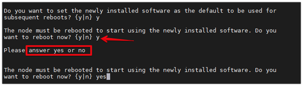
Note: When installing new software, the system might perform firmware upgrades to the BIOS and adapter cards, causing reboots and possible stops at the Loader-A prompt. If these actions occur, the system might deviate from this procedure.
Note: During the ONTAP installation, a prompt to reboot the node requests a Y/N response. The prompt requires the entire Yes or No response to reboot the node and continue the installation.
Step 16. Press Ctrl-C when the following message displays:
Press Ctrl-C for Boot Menu
Step 17. Select option 4 for Clean Configuration and Initialize All Disks.
Step 18. Enter y to zero disks, reset config, and install a new file system.
Step 19. Enter yes to erase all the data on the disks.
Note: When the initialization and creation of the root aggregate is complete, the storage system reboots. You can continue with the configuration of node 02 while the initialization and creation of the root aggregate for node 01 is in progress. For more information about root aggregate and disk partitioning, refer to the ONTAP documentation on root-data partitioning: https://docs.netapp.com/us-en/ontap/concepts/root-data-partitioning-concept.html.
Procedure 2. Configure Node 02
Step 1. Connect to the storage system console port. You should see a Loader-B prompt. However, if the storage system is in a reboot loop, press Ctrl-C to exit the autoboot loop when the following message displays: Starting
AUTOBOOT press Ctrl-C to abort…
Step 2. Allow the system to boot up.
autoboot
Step 3. Press Ctrl-C when prompted.
Note: If NetApp ONTAP 9.13.1P3 is not the version of software being booted, continue with the following steps to install new software. If NetApp ONTAP 9.13.1P3 is the version being booted, select option 8 and y to reboot the node, then continue with section Set Up Node.
Step 4. To install new software, select option 7.
Step 5. Enter y to continue the installation.
Step 6. Select e0M for the network port you want to use for the download.
Step 7. Enter n to skip the reboot.
Step 8. Select option 7: Install new software first
Step 9. Enter y to continue the installation
Step 10. Enter the IP address, netmask, and default gateway for e0M.
Enter the IP address for port e0M: <node02-mgmt-ip>
Enter the netmask for port e0M: <node02-mgmt-mask>
Enter the IP address of the default gateway: <node02-mgmt-gateway>
Step 11. Enter the URL where the software can be found.
Step 12. The web server must be reachable (ping) from node 02.
<url-boot-software>
Step 13. Press Enter for the username, indicating no username.
Step 14. Enter y to set the newly installed software as the default to be used for subsequent reboots.
Step 15. Enter yes to reboot the node.

Note: When installing new software, the system might perform firmware upgrades to the BIOS and adapter cards, causing reboots and possible stops at the Loader-B prompt. If these actions occur, the system might deviate from this procedure.
Note: During the ONTAP installation a prompt to reboot the node requests a Y/N response. The prompt requires the entire Yes or No response to reboot the node and continue the installation.
Step 16. Press Ctrl-C when you see this message:
Press Ctrl-C for Boot Menu
Step 17. Select option 4 for Clean Configuration and Initialize All Disks.
Step 18. Enter y to zero disks, reset config, and install a new file system.
Step 19. Enter yes to erase all the data on the disks.
Step 1. From a console port program attached to the storage controller A (node 01) console port, run the node setup script. This script appears when ONTAP 9.13.1P3 boots on the node for the first time.
Step 2. Follow the prompts to set up node 01.
Welcome to node setup.
You can enter the following commands at any time:
"help" or "?" - if you want to have a question clarified,
"back" - if you want to change previously answered questions, and
"exit" or "quit" - if you want to quit the setup wizard.
Any changes you made before quitting will be saved.
You can return to cluster setup at any time by typing “cluster setup.”
To accept a default or omit a question, do not enter a value.
This system will send event messages and weekly reports to NetApp Technical Support.
To disable this feature, enter "autosupport modify -support disable" within 24 hours.
Enabling AutoSupport can significantly speed problem determination and resolution should a problem occur on your system.
For further information on AutoSupport, see: http://support.netapp.com/autosupport/
Type yes to confirm and continue {yes}: yes
Enter the node management interface port [e0M]: Enter
Enter the node management interface IP address: <node01-mgmt-ip>
Enter the node management interface netmask: <node01-mgmt-mask>
Enter the node management interface default gateway: <node01-mgmt-gateway>
A node management interface on port e0M with IP address <node01-mgmt-ip> has been created
Use your web browser to complete cluster setup by accesing https://<node01-mgmt-ip>. Otherwise press Enter to complete cluster setup using the command line interface.
Step 3. To complete cluster setup, open a web browser and navigate to https://<node01-mgmt-ip>.
Table 14. Cluster Create in ONTAP Prerequisites
| Cluster Detail |
Cluster Detail Value |
| Cluster name |
<clustername> |
| Cluster Admin SVM |
<cluster-adm-svm> |
| Infrastructure Data SVM |
<infra-data-svm> |
| ONTAP base license |
<cluster-base-license-key> |
| Cluster management IP address |
<clustermgmt-ip> |
| Cluster management netmask |
<clustermgmt-mask> |
| Cluster management gateway |
<clustermgmt-gateway> |
| Cluster node 01 IP address |
<node01-mgmt-ip> |
| Cluster node 01 netmask |
<node01-mgmt-mask> |
| Cluster node 01 gateway |
<node01-mgmt-gateway> |
| Cluster node 02 IP address |
<node02-mgmt-ip> |
| Cluster node 02 netmask |
<node02-mgmt-mask> |
| Cluster node 02 gateway |
<node02-mgmt-gateway> |
| Node 01 service processor IP address |
<node01-sp-ip> |
| Node 01 service processor network mask |
<node01-sp-mask> |
| Node 01 service processor gateway |
<node01-sp-gateway> |
| Node 02 service processor IP address |
<node02-sp-ip> |
| Node 02 service processor network mask |
<node02-sp-mask> |
| Node 02 service processor gateway |
<node02-sp-gateway> |
| Node 01 node name |
<st-node01> |
| Node 02 node name |
<st-node02> |
| DNS domain name |
<dns-domain-name> |
| DNS server IP address |
<dns-ip> |
| NTP server A IP address |
<switch-a-ntp-ip> |
| NTP server B IP address |
<switch-b-ntp-ip> |
| SNMPv3 User |
<snmp-v3-usr> |
| SNMPv3 Authentication Protocol |
<snmp-v3-auth-proto> |
| SNMPv3 Privacy Protocol |
<snmpv3-priv-proto> |
Note: Cluster setup can also be performed using the CLI. This document describes the cluster setup using the NetApp ONTAP System Manager guided setup.
Step 4. Complete the required information on the Initialize Storage System screen:
a. In the Cluster screen, enter the cluster name and administrator password.
b. Complete the Networking information for the cluster and each node.
| Tech tip |
| The nodes should be discovered automatically; if they are not, Refresh the browser page. By default, the cluster interfaces are created on all the new factory shipping storage controllers. If all the nodes are not discovered, then configure the cluster using the command line. The node management interface can be on the same subnet as the cluster management interface, or it can be on a different subnet. In this document, we assume that it is on the same subnet. |
c. Click Submit.
Step 5. A few minutes will pass while the cluster is configured. When prompted, login to ONTAP System Manager to continue the cluster configuration.
Step 6. From the Dashboard click the Cluster menu and click Overview.
Step 7. Click the More button in the Overview pane and click Edit.
Step 8. Add additional cluster configuration details and click Save to make the changes persistent:
● Cluster location
● DNS domain name
● DNS server IP addresses
● DNS server IP addresses can be added individually or with a comma separated list on a single line.
Step 9. Click Save to make the changes persistent.
Step 10. Select the Settings menu under the Cluster menu.
Step 11. If AutoSupport was not configured during the initial setup, click the ellipsis in the AutoSupport tile and select More options.
Step 12. To enable AutoSupport click the slider.
Step 13. Click Edit to change the transport protocol, add a proxy server address and a mail host as needed.
Step 14. Click Save to enable the changes.
Step 15. In the Email tile, click Edit and enter the desired email information:
● Email send from address
● Email recipient addresses
● Recipient Category
Step 16. Click Save when complete.
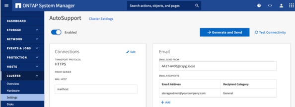
Step 17. Select CLUSTER > Settings to return to the cluster settings page.
Step 18. Locate the Licenses tile on the right and click the arrow.
Step 19. Add the desired licenses to the cluster by clicking Add and entering the license keys in a comma separated list.
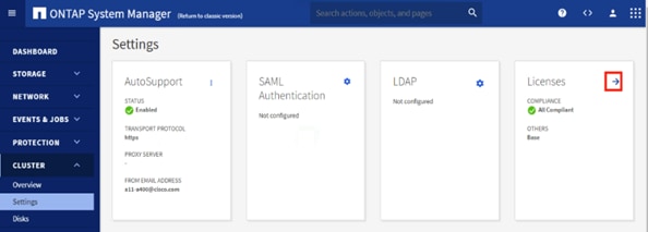
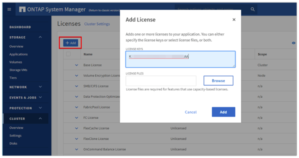
Note: NetApp ONTAP 9.10.1 and later for FAS/AFF storage systems uses a new file-based licensing solution to enable per-node NetApp ONTAP features. The new license key format is referred to as a NetApp License File, or NLF. For more information, go to: NetApp ONTAP 9.10.1 and later Licensing Overview - NetApp Knowledge Base
Step 20. Configure storage aggregates by selecting the Storage menu and selecting Tiers.
Step 21. Click Add Local Tier and allow ONTAP System Manager to recommend a storage aggregate configuration.
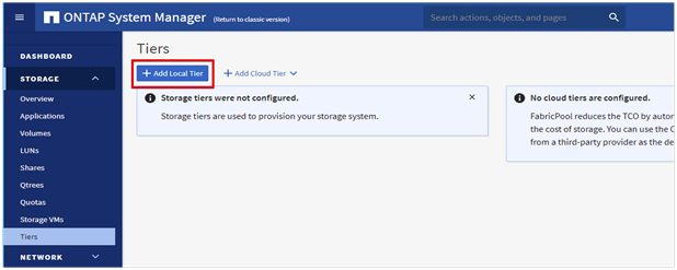
Step 22. ONTAP will use best practices to recommend an aggregate layout. Click the Recommended details link to view the aggregate information.
Step 23. Optionally, enable NetApp Aggregate Encryption (NAE) by checking the box for Configure Onboard Key Manager for encryption.
Step 24. Enter and confirm the passphrase and save it in a secure location for future use.
Step 25. Click Save to make the configuration persistent.
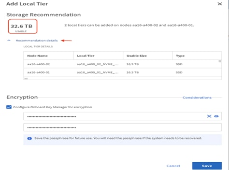
Note: Aggregate encryption may not be supported for all deployments. Please review the NetApp Encryption Power Guide and the Security Hardening Guide for NetApp ONTAP 9 (TR-4569) to help determine if aggregate encryption is right for your environment.
Procedure 4. Log into the Cluster
Step 1. Open an SSH connection to either the cluster IP or the host name.
Step 2. Log into the admin user with the password you provided earlier.
Procedure 5. Verify Storage Failover
Step 1. Verify the status of the storage failover:
A400-VDI-Cluster::> storage failover show
Takeover
Node Partner Possible State Description
-------------- -------------- -------- -------------------------------------
A400-VDI-Cluster-01
A400-VDI- true Connected to A400-VDI-Cluster-02
Cluster-02
A400-VDI-Cluster-02
A400-VDI- true Connected to A400-VDI-Cluster-01
Cluster-01
2 entries were displayed.
Note: Both <st-node01> and <st-node02> must be capable of performing a takeover. Continue with Step 2 if the nodes can perform a takeover.
Step 2. Enable failover on one of the two nodes if it was not completed during the installation:
storage failover modify -node <st-node01> -enabled true
Note: Enabling failover on one node enables it for both nodes.
Step 3. Verify the HA status for a two-node cluster:
Note: This step is not applicable for clusters with more than two nodes.
A400-VDI-Cluster ::> cluster ha show
High-Availability Configured: true
Note: If HA is not configured use the following commands. Only enable HA mode for two-node clusters. Do not run this command for clusters with more than two nodes because it causes problems with failover.
cluster ha modify -configured true
Do you want to continue? {y|n}: y
Step 4. Verify that hardware assist is correctly configured:
A400-VDI-Cluster::> storage failover hwassist show
Node
-----------------
A400-VDI-Cluster-01
Partner: A400-VDI-Cluster-02
Hwassist Enabled: true
Hwassist IP: 192.X.X.84
Hwassist Port: 162
Monitor Status: active
Inactive Reason: -
Corrective Action: -
Keep-Alive Status: healthy
A400-VDI-Cluster-02
Partner: A400-VDI-Cluster-01
Hwassist Enabled: true
Hwassist IP: 192.X.X.85
Hwassist Port: 162
Monitor Status: active
Inactive Reason: -
Corrective Action: -
Keep-Alive Status: healthy
2 entries were displayed.
Procedure 6. Set Auto-Revert on Cluster Management Interface
Step 1. Set the auto-revert parameter on the cluster management interface:
Note: A storage virtual machine (SVM) is referred to as a Vserver or vserver in the GUI and CLI.
network interface modify -vserver <clustername> -lif cluster_mgmt_lif_1 -auto-revert true
Procedure 7. Zero All Spare Disks
Step 1. Zero all spare disks in the cluster by running the following command:
disk zerospares
| Tech tip |
| Advanced Data Partitioning creates a root partition and two data partitions on each SSD drive in an AFF configuration. Disk autoassign should have assigned one data partition to each node in an HA pair. If a different disk assignment is required, disk autoassignment must be disabled on both nodes in the HA pair by running the disk option modify command. Spare partitions can then be moved from one node to another by running the disk removeowner and disk assign commands. |
Procedure 8. Set Up Service Processor Network Interface
Step 1. Assign a static IPv4 address to the Service Processor on each node by running the following commands:
system service-processor network modify –node <st-node01> -address-family IPv4 –enable true –dhcp none –ip-address <node01-sp-ip> -netmask <node01-sp-mask> -gateway <node01-sp-gateway>
system service-processor network modify –node <st-node02> -address-family IPv4 –enable true –dhcp none –ip-address <node02-sp-ip> -netmask <node02-sp-mask> -gateway <node02-sp-gateway>
Note: The Service Processor IP addresses should be in the same subnet as the node management IP addresses.
Procedure 9. Create Manual Provisioned Aggregates - Optional
Note: An aggregate containing the root volume is created during the ONTAP setup process. To manually create additional aggregates, determine the aggregate name, the node on which to create it, and the number of disks it should contain.
Step 1. Create new aggregates by running the following commands:
storage aggregate create -aggregate <aggr1_node01> -node <st-node01> -diskcount <num-disks> -diskclass solid-state
storage aggregate create -aggregate <aggr1_node02> -node <st-node02> -diskcount <num-disks> -diskclass solid-state
Note: You should have the minimum number of hot spare disks for the recommended hot spare disk partitions for their aggregate.
Note: For all-flash aggregates, you should have a minimum of one hot spare disk or disk partition. For non-flash homogenous aggregates, you should have a minimum of two hot spare disks or disk partitions. For Flash Pool aggregates, you should have a minimum of two hot spare disks or disk partitions for each disk type.
| Tech tip |
| In an AFF configuration with a small number of SSDs, you might want to create an aggregate with all, but one remaining disk (spare) assigned to the controller. |
Note: The aggregate cannot be created until disk zeroing completes. Run the storage aggregate show command to display the aggregate creation status. Do not proceed until both aggr1_node01 and aggr1_node02 are online.
Procedure 10. Remove Default Broadcast Domains
Note: By default, all network ports are included in separate default broadcast domain. Network ports used for data services (for example, e0e, e0f, and so on) should be removed from their default broadcast domain and that broadcast domain should be deleted.
Step 1. Run the following commands:
network port broadcast-domain delete -broadcast-domain <Default-N> -ipspace Default
network port broadcast-domain show
Step 2. Delete the Default broadcast domains with Network ports (Default-1, Default-2, and so on). This does not include Cluster ports and management ports.
Procedure 11. Disable Flow Control on 25/100GbE Data Ports
Step 1. Disable the flow control on 25 and 100GbE data ports by running the following command to configure the ports on node 01:
network port modify -node <st-node01> -port e0e,e0f,e0g,e0h -flowcontrol-admin none
Step 2. Run the following command to configure the ports on node 02:
network port modify -node <st-node02> -port e0e,e0f,e0g,e0h -flowcontrol-admin none
Note: Disable flow control only on ports that are used for data traffic.
Procedure 12. Enable Cisco Discovery Protocol
Step 1. Enable the Cisco Discovery Protocol (CDP) on the NetApp storage controllers by running the following command to enable CDP in ONTAP:
node run -node * options cdpd.enable on
Procedure 13. Enable Link-layer Discovery Protocol on all Ethernet Ports
Step 1. Enable the exchange of Link-layer Discovery Protocol (LLDP) neighbor information between the storage and network switches, on all ports, of all nodes in the cluster, by running the following command:
node run * options lldp.enable on
Procedure 14. Enable FIPS Mode on the NetApp ONTAP Cluster - Optional
NetApp ONTAP is compliant in the Federal Information Processing Standards (FIPS) 140-2 for all SSL connections. When SSL FIPS mode is enabled, SSL communication from NetApp ONTAP to external client or server components outside of NetApp ONTAP will use FIPS compliant crypto for SSL.
Step 1. To enable FIPS on the NetApp ONTAP cluster, run the following commands:
set -privilege advanced
security config modify -interface SSL -is-fips-enabled true
Note: If you are running NetApp ONTAP 9.8 or earlier manually reboot each node in the cluster one by one. Beginning in NetApp ONTAP 9.9.1, rebooting is not required.
Procedure 15. Configure Timezone
Step 1. To configure time synchronization on the cluster, follow this step:
timezone -timezone <timezone>
Note: For example, in the eastern United States, the time zone is America/New_York.
Procedure 16. Configure Simple Network Management Protocol - SNMP
Note: If you enabled FIPS then look at the following points while configuring SNMP.
Note: The SNMP users or SNMP traphosts that are non-compliant with FIPS will be deleted automatically. “Configure SNMP traphosts” configuration will be non-compliant with FIPS.
Note: The SNMPv1 user, SNMPv2c user (After configuring SNMP community) or SNMPv3 user (with none or MD5 as authentication protocol or none or DES as encryption protocol or both) is non-compliant with FIPS.
Step 1. Configure basic SNMP information, such as the location and contact. When polled, this information is visible as the sysLocation and sysContact variables in SNMP.
snmp contact <snmp-contact>
snmp location “<snmp-location>”
snmp init 1
options snmp.enable on
Step 2. Configure SNMP traps to send to remote hosts, such as an Active IQ Unified Manager server or another fault management system.
Note: This step works when FIPS is disabled.
Note: An SNMPv1 traphost or SNMPv3 traphost (configured with an SNMPv3 user non-compliant to FIPS) is non-compliant to FIPS.
snmp traphost add <oncommand-um-server-fqdn>
Step 3. Configure SNMP community.
Note: This step works when FIPS is disabled.
Note: SNMPv1 and SNMPv2c are not supported when cluster FIPS mode is enabled.
system snmp community add -type ro -community-name -vserver
Note: In new installations of NetApp ONTAP, SNMPv1 and SNMPv2c are disabled by default. SNMPv1 and SNMPv2c are enabled after you create an SNMP community.
Note: NetApp ONTAP supports read-only communities.
Procedure 17. Configure SNMPv3 Access
Note: SNMPv3 offers advanced security by using encryption and passphrases. The SNMPv3 user can run SNMP utilities from the traphost using the authentication and privacy settings that you specify.
Note: Configure SNMP traps to send to remote hosts, such as an Active IQ Unified Manager server or another fault management system.
When FIPS is enabled, the following are the supported/compliant options for authentication and privacy protocol:
● Authentication Protocol: sha, sha2-256
● Privacy protocol: aes128
Step 1. Configure the SNMPv3 access by running the following command:
security login create -user-or-group-name <<snmp-v3-usr>> -application snmp -authentication-method usm
Enter the authoritative entity's EngineID [local EngineID]:
Which authentication protocol do you want to choose (none, md5, sha, sha2-256) [none]: <<snmp-v3-auth-proto>>
Enter the authentication protocol password (minimum 8 characters long):
Enter the authentication protocol password again:
Which privacy protocol do you want to choose (none, des, aes128) [none]: <<snmpv3-priv-proto>>
Enter privacy protocol password (minimum 8 characters long):
Enter privacy protocol password again:
Note: Refer to the NetApp SNMP Configuration Express Guide for additional information when configuring SNMPv3 security users.
Procedure 18. Configure login banner for the NetApp ONTAP Cluster
Step 1. To create login banner for the NetApp ONTAP cluster, run the following command:
security login banner modify -message "Access restricted to authorized users" -vserver <clustername>
Procedure 19. Remove insecure ciphers from the NetApp ONTAP Cluster
Step 1. Ciphers with the suffix CBC are considered insecure. To remove the CBC ciphers, run the following NetApp ONTAP command:
security ssh remove -vserver <clustername> -ciphers aes256-cbc,aes192-cbc,aes128-cbc,3des-cbc
Procedure 20. Create Management Broadcast Domain
Step 1. If the management interfaces are required to be on a separate VLAN, create a new broadcast domain for those interfaces by running the following command:
network port broadcast-domain create -broadcast-domain IB-MGMT -mtu 1500
Procedure 21. Create NFS Broadcast Domain
Step 1. To create an NFS, data broadcast domain with a maximum transmission unit (MTU) of 9000, run the following commands to create a broadcast domain for NFS in ONTAP:
network port broadcast-domain create -broadcast-domain Infra-NFS -mtu 9000
Procedure 22. Create CIFS Broadcast Domain
Step 1. To create a CIFS data broadcast domain with a maximum transmission unit (MTU) of 9000, run the following commands to create a broadcast domain for CIFS in ONTAP:
network port broadcast-domain create -broadcast-domain CIFS-VLAN -mtu 9000
Procedure 23. Create Interface Groups
Step 1. To create the LACP interface groups for the 25GbE data interfaces, run the following commands:
network port ifgrp create -node <st-node01> -ifgrp a0a -distr-func port -mode multimode_lacp
network port ifgrp add-port -node <st-node01> -ifgrp a0a -port e0e
network port ifgrp add-port -node <st-node01> -ifgrp a0a -port e0f
network port ifgrp add-port -node <st-node01> -ifgrp a0a -port e0g
network port ifgrp add-port -node <st-node01> -ifgrp a0a -port e0h
network port ifgrp create -node <st-node02> -ifgrp a0a -distr-func port -mode multimode_lacp
network port ifgrp add-port -node <st-node02> -ifgrp a0a -port e0e
network port ifgrp add-port -node <st-node02> -ifgrp a0a -port e0f
network port ifgrp add-port -node <st-node02> -ifgrp a0a -port e0g
network port ifgrp add-port -node <st-node02> -ifgrp a0a -port e0h
Step 2. To verify, run the following:
A400-VDI-Cluster::> network port ifgrp show
Port Distribution Active
Node IfGrp Function MAC Address Ports Ports
-------- ---------- ------------ ----------------- ------- -------------------
A400-VDI-Cluster-01
a0a port d2:39:ea:40:53:32 full e0e, e0f, e0g, e0h
A400-VDI-Cluster-02
a0a port d2:39:ea:45:2d:36 full e0e, e0f, e0g, e0h
2 entries were displayed.
Procedure 24. Change MTU on Interface Groups
Step 1. To change the MTU size on the base interface-group ports before creating the VLAN ports, run the following commands:
network port modify –node <st-node01> -port a0a –mtu 9000
network port modify –node <st-node02> -port a0a –mtu 9000
Step 1. Create the management VLAN ports and add them to the management broadcast domain:
network port vlan create –node <st-node01> -vlan-name a0a-<ib-mgmt-vlan-id>
network port vlan create –node <st-node02> -vlan-name a0a-<ib-mgmt-vlan-id>
network port broadcast-domain add-ports -broadcast-domain IB-MGMT -ports <st-node01>:a0a-<ib-mgmt-vlan-id>,<st-node02>:a0a-<ib-mgmt-vlan-id>
Step 2. Create the NFS VLAN ports and add them to the Infra-NFS broadcast domain:
network port vlan create –node <st-node01> -vlan-name a0a-<infra-nfs-vlan-id>
network port vlan create –node <st-node02> -vlan-name a0a-<infra-nfs-vlan-id>
network port broadcast-domain add-ports -broadcast-domain Infra-NFS -ports <st-node01>:a0a-<infra-nfs-vlan-id>,<st-node02>:a0a-<infra-nfs-vlan-id>
Step 3. Create the CIFS VLAN ports and add them to the Infra-CIFS broadcast domain:
network port vlan create –node <st-node01> -vlan-name a0a-<cifs-vlan>
network port vlan create –node <st-node02> -vlan-name a0a-<cifs-vlan>
network port broadcast-domain add-ports -broadcast-domain CIFS-VLAN -ports <st-node01>:a0a-<infra-cifs-vlan-id>,<st-node02>:a0a-<infra-cifs-vlan-id>
Step 4. To verify, run the following command:
A400-VDI-Cluster::> network port vlan show
Network Network
Node VLAN Name Port VLAN ID MAC Address
------ --------- ------- -------- -----------------
A400-VDI-Cluster-01
a0a-31 a0a 31 d2:39:ea:40:53:32
a0a-32 a0a 32 d2:39:ea:40:53:32
a0a-33 a0a 33 d2:39:ea:40:53:32
A400-VDI-Cluster-02
a0a-31 a0a 31 d2:39:ea:45:2d:36
a0a-33 a0a 32 d2:39:ea:45:2d:36
a0a-33 a0a 33 d2:39:ea:45:2d:36
8 entries were displayed.
Procedure 26. Create an Infrastructure SVM
Step 1. Run the vserver create command:
vserver create –vserver Infra-SVMAdd the required data protocols to the SVM:
Vserver add-protocols -protocols nfscifs -vserver Infra-SVM
Note: For FC-NVMe configuration, add “fcp” and “nvme” protocols to the SVM.
Note: For NVMe/TCP configuration with iSCSI booting, add “nvme” and “iscsi” protocols to the SVM.
Step 2. Remove the unused data protocols from the SVM:
Vserver remove-protocols –vserver Infra-SVM -protocols iscsi,fcp
Note: It is recommended to remove iSCSI or FCP protocols if the protocol is not in use (in this case iSCSI was removed).
Step 3. Add the two data aggregates to the Infra-SVM aggregate list for the NetApp ONTAP Tools:
vserver modify –vserver Infra-SVM –aggr-list <aggr1_node01>,<aggr1_node02>
Step 4. Enable and run the NFS protocol in the Infra-SVM:
vserver nfs create -vserver Infra-SVM -udp disabled -v3 enabled -v4.1 enabled -vstorage enabled
Note: If the NFS license was not installed during the cluster configuration, make sure to install the license before starting the NFS service.
Step 5. Verify the NFS vstorage parameter for the NetApp NFS VAAI plug-in was enabled:
A400-VDI-Cluster::> vserver nfs show -fields vstorage
vserver vstorage
--------- --------
Infra-SVM enabled
Procedure 27. Configure CIFS Servers
Note: You can enable and configure CIFS servers on storage virtual machines (SVMs) with NetApp FlexVol®️ volumes to let SMB clients access files on your cluster. Each data SVM in the cluster can be bound to exactly one Active Directory domain. However, the data SVMs do not need to be bound to the same domain. Each data SVM can be bound to a unique Active Directory domain.
Step 1. To configure DNS for the Infra-SVM, run the following command:
dns create -vserver <vserver-name> -domains <dns-domain> -nameserve <dns-servers>
Example:
dns create -vserver Infra-SVM -domains flexpodb4.cisco.com -nameservers 10.102.1.151,10.102.1.152
Note: The node management network interfaces should be able to route to the Active Directory domain controller to which you want to join the CIFS server. Alternatively, a data network interface must exist on the SVM that can route to the Active Directory domain controller.
Step 2. Create a network interface on the IB-MGMT VLAN:
network interface create –vserver Infra-SVM –lif svm-mgmt -service-policy default-management –home-node <st-node01> -home-port a0a-<ib-mgmt-vlan-id> –address <svm-mgmt-ip> -netmask <svm-mgmt-mask> -status-admin up –failover-policy broadcast-domain-wide –auto-revert true
Step 3. Create the CIFS service:
vserver cifs create -vserver Infra-SVM -cifs-server Infra-CIFS -domain <domain.com>
In order to create an Active Directory machine account for the CIFS server, you must supply the name and password of a Windows account with sufficient privileges to add computers to the "CN=Computers" container within the"DOMAIN.COM" domain.
Enter the user name: Administrator@active_diectory.local
Enter the password:
Procedure 28. Modify Storage Virtual Machine Option
Note: NetApp ONTAP can use automatic node referrals to increase SMB client performance on SVMs with FlexVol volumes. This feature allows the SVM to automatically redirect a client request to a network interface on the node where the FlexVol volume resides.
Step 1. Run the following command to enable automatic node referrals on your SVM:
set -privilege advanced
vserver cifs options modify -vserver Infra-SVM -is-referral-enabled true
Procedure 29. Create Load-Sharing Mirrors of a SVM Root Volume
Step 1. Create a volume to be the load-sharing mirror of the infrastructure SVM root volume on each node:
volume create –vserver Infra-SVM –volume Infra-SVM_root_m01 –aggregate <aggr1_node01> –size 1GB –type DP
volume create –vserver Infra-SVM –volume Infra-SVM_root_m02 –aggregate <aggr1_node02> –size 1GB –type DP
Step 2. Create a job schedule to update the root volume mirror relationships every 15 minutes:
job schedule interval create -name 15min -minutes 15
Step 3. Create the mirroring relationships:
snapmirror create –source-path Infra-SVM:Infra_SVM_root -destination-path Infra-SVM:Infra_SVM _root_m01 –type LS -schedule 15min
snapmirror create –source-path Infra-SVM:Infra_SVM_root –destination-path Infra-SVM: Infra_SVM_root_m02 –type LS -schedule 15min
Step 4. Initialize the mirroring relationships:
snapmirror initialize-ls-set –source-path Infra-SVM:Infra_SVM_root
Step 5. To verify, run the following:
A400-VDI-Cluster::> snapmirror show -type ls
Progress
Source Destination Mirror Relationship Total Last
Path Type Path State Status Progress Healthy Updated
----------- ---- ------------ ------- -------------- --------- ------- --------
A400-VDI-Cluster://Infra-SVM/Infra_SVM_root
LS A400-VDI-Cluster://Infra-SVM/Infra_SVM_root_m01
Snapmirrored
Idle - true -
A400-VDI-Cluster://Infra-SVM/Infra_SVM_root_m02
Snapmirrored
Idle - true -
2 entries were displayed.
Procedure 30. Configure HTTPS Access to the Storage Controller
Step 1. Increase the privilege level to access the certificate commands:
set -privilege diag
Do you want to continue? {y|n}: y
Step 2. Generally, a self-signed certificate is already in place. Verify the certificate and obtain parameters (for example, the <serial-number>) by running the following command:
security certificate show
Step 3. For each SVM shown, the certificate common name should match the DNS fully qualified domain name (FQDN) of the SVM. Delete the two default certificates and replace them with either self-signed certificates or certificates from a certificate authority (CA). To delete the default certificates, run the following commands:
security certificate delete -vserver Infra-SVM -common-name Infra-SVM -ca Infra-SVM -type server -serial <serial-number>
Note: Deleting expired certificates before creating new certificates is a best practice. Run the security certificate delete command to delete the expired certificates. In the following command, use TAB completion to select and delete each default certificate.
Step 4. To generate and install self-signed certificates, run the following commands as one-time commands. Generate a server certificate for the Infra-SVM and the cluster SVM. Use TAB completion to aid in the completion of these commands:
security certificate create -common-name <cert-common-name> -type server -size 2048 -country <cert-country> -state <cert-state> -locality <cert-locality> -organization <cert-org> -unit <cert-unit> -email-addr <cert-email> -expire-days <cert-days> -protocol SSL -hash-function SHA256 -vserver Infra-SVM
Step 5. To obtain the values for the parameters required in step 5 (<cert-ca> and <cert-serial>), run the security certificate show command.
Step 6. Enable each certificate that was just created by using the –server-enabled true and –client-enabled false parameters. Use TAB completion to aid in the completion of these commands:
security ssl modify -vserver <clustername> -server-enabled true -client-enabled false -ca <cert-ca> -serial <cert-serial> -common-name <cert-common-name>
Step 7. Disable HTTP cluster management access:
network interface service-policy remove-service -vserver <clustername> -policy default-management -service management-http
Note: It is normal for some of these commands to return an error message stating that the entry does not exist.
Step 8. Return to the normal admin privilege level and verify that the system logs are available in a web browser:
set –privilege admin
https://<node01-mgmt-ip>/spi
https://<node02-mgmt-ip>/spi
Procedure 31. Set password for SVM vsadmin user and unlock the user
Step 1. Set a password for the SVM vsadmin user and unlock the user using the following commands:
security login password –username vsadmin –vserver Infra-SVM
Enter a new password: <password>
Enter it again: <password>
security login unlock –username vsadmin –vserver Infra-SVM
Procedure 32. Configure login banner for the SVM
Step 1. To create login banner for the SVM, run the following command:
Security login banner modify -vserver Infra-SVM -message "This Infra-SVM is reserved for authorized users only!"
Procedure 33. Remove insecure ciphers from the SVM
Step 1. Ciphers with the suffix CBC are considered insecure. To remove the CBC ciphers, run the following NetApp ONTAP command:
security ssh remove -vserver Infra-SVM -ciphers aes256-cbc,aes192-cbc,aes128-cbc,3des-cbc
Procedure 34. Configure Export Policy Rule
Step 1. Create a new rule for the infrastructure NFS subnet in the default export policy:
vserver export-policy rule create –vserver Infra-SVM -policyname default –ruleindex 1 –protocol nfs -clientmatch <infra-nfs-subnet-cidr> -rorule sys –rwrule sys -superuser sys –allow-suid true
Step 2. Assign the FlexPod export policy to the infrastructure SVM root volume:
volume modify –vserver Infra-SVM –volume Infra_SVM_root –policy default
Procedure 35. Create CIFS Export Policy
Note: Optionally, you can use export policies to restrict CIFS access to files and folders on CIFS volumes. You can use export policies in combination with share level and file level permissions to determine effective access rights.
Step 1. Run the following command to create an export policy that limits access to devices in the domain:
export-policy create -vserver Infra-SVM -policyname cifs_policy
export-policy rule create -vserver Infra-SVM -policyname cifs_policy -clientmatch <domain_name> -rorule
krb5i,krb5p -rwrule krb5i,krb5p
Procedure 36. Create a NetApp FlexVol Volume
The following information is required to create a NetApp FlexVol volume:
● The volume name
● The volume size
● The aggregate on which the volume exists
Step 1. To create FlexVols for datastores, run the following commands:
volume create -vserver Infra-SVM -volume infra_datastore -aggregate <aggr1_node01> -size 1TB -state online -policy default -junction-path /infra_datastore -space-guarantee none -percent-snapshot-space 0
Note: If you are going to setup and use SnapCenter to backup the infra_datastore volume, add “- snapshot-policy none” to the end of the volume create command for the infra_datastore volume.
Step 2. Create vCLS datastores to be used by the vSphere environment to host vSphere Cluster Services (vCLS) VMs using the command below:
volume create -vserver Infra-SVM -volume vCLS -aggregate <aggr1_node02> -size 100GB -state online -policy default -junction-path /vCLS -space-guarantee none -percent-snapshot-space 0
Step 3. To create swap volumes, run the following commands:
volume create -vserver Infra-SVM -volume infra_swap -aggregate <aggr1_node01> -size 200GB -state online -policy default -junction-path /infra_swap -space-guarantee none -percent-snapshot-space 0 -snapshot-policy none.
Step 4. To create a FlexVol for the boot LUNs of servers, run the following command:
volume create -vserver Infra-SVM -volume esxi_boot -aggregate <aggr1_node01> -size 320GB -state online -policy default -space-guarantee none -percent-snapshot-space 0
Step 5. Run the following command to create a FlexVol for storing SVM audit log configuration:
volume create -vserver Infra-SVM -volume audit_log -aggregate <aggr1_node01> -size 50GB -state online -policy default -junction-path /audit_log -space-guarantee none -percent-snapshot-space 0
Procedure 37. Create a NetApp FlexGroup Volume
Step 1. To create CIFS volumes, run the following commands:
volume create -vserver Infra-SVM -volume cifs_vol_01 -aggr-list aggr01_node01,aggr01_node02 -aggr-list-multiplier 4 -state online –policy cifs_policy -size 2TB -junction-path /cifs_vol_01 -space-guarantee none -percent-snapshot-space 0
volume create -vserver Infra-SVM -volume cifs_vol_02 -aggr-list aggr01_node01,aggr01_node02 -aggr-list-multiplier 4 -state online –policy cifs_policy -size 800GB -junction-path /cifs_vol_02 -space-guarantee none -percent-snapshot-space 0
volume create -vserver Infra-SVM -volume cifs_vol_03 -aggr-list aggr01_node01,aggr01_node02 -aggr-list-multiplier 4-state online –policy cifs_policy -size 800GB -junction-path /cifs_vol_03 -space-guarantee none -percent-snapshot-space 0
Step 2. Update set of load-sharing mirrors using the command below:
snapmirror update-ls-set -source-path Infra-SVM:Infra_SVM_root
Note: If you are going to setup and use SnapCenter to backup the infra_datastore volume, add “-snapshot-policy none” to the end of the volume create command for the infra_datastore volume.
Procedure 38. Disable Volume Efficiency on swap volume
Step 1. On NetApp AFF systems, deduplication is enabled by default. To disable the efficiency policy on the infra_swap volume, run the following command:
volume efficiency off –vserver Infra-SVM –volume infra_swap
Procedure 39. Create CIFS Shares
Note: A CIFS share is a named access point in a volume that enables CIFS clients to view, browse, and manipulate files on a file server.
Step 1. Run the following commands to create CIFS shares:
cifs share create -vserver Infra-SVM -share-name <CIFS_share_1> -path /cifs_vol_01 -share properties oplocks,browsable,continuously-available,showsnapshot
cifs share create -vserver Infra-SVM -share-name <CIFS_share_2> -path /cifs_vol_02 -share properties oplocks,browsable,continuously-available,showsnapshot
cifs share create -vserver Infra-SVM -share-name <CIFS_share_3> -path /cifs_vol_03 -share properties oplocks,browsable,continuously-available,showsnapshot
Step 1. Run the following commands to create NFS LIFs:
network interface create -vserver Infra-SVM -lif nfs-lif-01 -service-policy default-data-files -home-node <st-node01> -home-port a0a-<infra-nfs-vlan-id> –address <node01-nfs-lif-01-ip> -netmask <node01-nfs-lif-01-mask> -status-admin up –failover-policy broadcast-domain-wide –auto-revert true
network interface create -vserver Infra-SVM -lif nfs-lif-02 -service-policy default-data-files -home-node <st-node02> -home-port a0a-<infra-nfs-vlan-id> –address <node02-nfs-lif-02-ip> -netmask <node02-nfs-lif-02-mask>-status-admin up –failover-policy broadcast-domain-wide –auto-revert true
Step 2. Run the following commands to verify:
A400-VDI-Cluster::> network interface show -vserver Infra-SVM -service-policy default-data-files
Logical Status Network Current Current Is
Vserver Interface Admin/Oper Address/Mask Node Port Home
----------- ---------- ---------- ------------------ ------------- ------- ----
Infra-SVM
nfs-lif-01 up/up 10.10.33.113/24 A400-VDI-Cluster-01
a0a-33 true
nfs-lif-02 up/up 10.10.33.114/24 A400-VDI-Cluster-02
a0a-33 true
2 entries were displayed.
Procedure 41. Create CIFS LIFs
Step 1. Run the following commands to create CIFS LIFs:
network interface create -vserver Infra-SVM -lif cifs_lif01 -service-policy default-data-files -home-node <st-node01> -home-port a0a-<infra-cifs-vlan-id> –address <node01-cifs_lif01-ip> -netmask <node01-cifs_lif01-mask> -status-admin up –failover-policy broadcast-domain-wide –auto-revert true
network interface create -vserver Infra-SVM -lif cifs_lif02 -service-policy default-data-files -home-node <st-node02> -home-port a0a-<infra-cifs-vlan-id> –address <node02-cifs_lif02-ip> -netmask <node02-cifs_lif02-mask>> -status-admin up –failover-policy broadcast-domain-wide –auto-revert true
Step 1. Create a default route that enables the SVM management interface to reach the outside world:
network route create –vserver Infra-SVM -destination 0.0.0.0/0 –gateway <svm-mgmt-gateway>
Step 2. To verify, run the following:
A400-VDI-Cluster::> network route show -vserver Infra-SVM
Vserver Destination Gateway Metric
------------------- --------------- --------------- ------
Infra-SVM
0.0.0.0/0 10.10.31.1 20
Note: A cluster serves data through at least one and possibly several SVMs. By completing these steps, you have created a single data SVM. You can create additional SVMs depending on their requirement.
Procedure 43. Configure AutoSupport
Step 1. NetApp AutoSupport sends support summary information to NetApp through HTTPS. To configure AutoSupport using command-line interface, run the following command:
system node autosupport modify -node * -state enable –mail-hosts -transport https -support enable -from <storage-admin-email> -to <storage-admin-email>
Cisco Intersight Managed Mode Configuration
This chapter contains the following:
● Cisco Intersight Managed Mode on Cisco UCS Fabric Interconnects
● Configure a Cisco UCS Domain Profile
● Cisco UCS Domain Configuration
● Configure Server Profile Template
The Cisco Intersight platform is a management solution delivered as a service with embedded analytics for Cisco and third-party IT infrastructures. The Cisco Intersight managed mode (also referred to as Cisco IMM or Intersight managed mode) is a new architecture that manages Cisco Unified Computing System (Cisco UCS) fabric interconnect–attached systems through a Redfish-based standard model. Cisco Intersight managed mode standardizes both policy and operation management Cisco UCS X210c M7compute nodes used in this deployment guide.
Cisco Intersight Managed Mode on Cisco UCS Fabric Interconnects
This section contains the following procedures:
● Set up Cisco Intersight Managed Mode on Cisco UCS Fabric Interconnects
● Set up a new Cisco Intersight account
● Set up Cisco Intersight account and associate it with Cisco Smart Licensing
● Set up Cisco Intersight Resource Group
● Set up Cisco Intersight Organization
● Claim Cisco UCS Fabric Interconnects in Cisco Intersight
● Verify the addition of Cisco UCS Fabric Interconnects to Cisco Intersight
Procedure 1. Set up Cisco Intersight Managed Mode on Cisco UCS Fabric Interconnects
Note: The Cisco UCS fabric interconnects need to be set up to support Cisco Intersight managed mode. When converting an existing pair of Cisco UCS fabric interconnects from Cisco UCS Manager mode to Intersight Mange Mode (IMM), first erase the configuration and reboot your system.
WARNING! Converting fabric interconnects to Cisco Intersight Managed Mode is a disruptive process, and configuration information will be lost. You are encouraged to make a backup of their existing configuration.
Step 1. Configure Fabric Interconnect A (FI-A). On the Basic System Configuration Dialog screen, set the management mode to Intersight. All the remaining settings are like those for the Cisco UCS Manager managed mode (UCSM-Managed).
Cisco UCS Fabric Interconnect A
To configure the Cisco UCS for use in a FlexPod environment in intersight managed mode, follow these steps:
Step 2. Connect to the console port on the first Cisco UCS fabric interconnect.
Enter the configuration method. (console/gui) ? console
Enter the management mode. (ucsm/intersight)? intersight
You have chosen to setup a new Fabric interconnect in “intersight” managed mode. Continue? (y/n): y
Enforce strong password? (y/n) [y]: Enter
Enter the password for "admin": <password>
Confirm the password for "admin": <password>
Enter the switch fabric (A/B) []: A
Enter the system name: <ucs-cluster-name>
Physical Switch Mgmt0 IP address : <ucsa-mgmt-ip>
Physical Switch Mgmt0 IPv4 netmask : <ucsa-mgmt-mask>
IPv4 address of the default gateway : <ucsa-mgmt-gateway>
Configure the DNS Server IP address? (yes/no) [n]: y
DNS IP address : <dns-server-1-ip>
Configure the default domain name? (yes/no) [n]: y
Default domain name : <ad-dns-domain-name>
<SNIP>
Verify and save the configuration.
Step 3. After applying the settings, make sure you can ping the fabric interconnect management IP address. When Fabric Interconnect A is correctly set up and is available, Fabric Interconnect B will automatically discover Fabric Interconnect A during its setup process as shown in the next step.
Step 4. Configure Fabric Interconnect B (FI-B). For the configuration method, choose console. Fabric Interconnect B will detect the presence of Fabric Interconnect A and will prompt you to enter the admin password for Fabric Interconnect A. Provide the management IP address for Fabric Interconnect B and apply the configuration.
Cisco UCS Fabric Interconnect A
Enter the configuration method. (console/gui) ? console
Installer has detected the presence of a peer Fabric interconnect. This Fabric interconnect will be added to the cluster. Continue (y/n) ? y
Enter the admin password of the peer Fabric interconnect: <password>
Connecting to peer Fabric interconnect... done
Retrieving config from peer Fabric interconnect... done
Peer Fabric interconnect Mgmt0 IPv4 Address: <ucsa-mgmt-ip>
Peer Fabric interconnect Mgmt0 IPv4 Netmask: <ucsa-mgmt-mask>
Peer FI is IPv4 Cluster enabled. Please Provide Local Fabric Interconnect Mgmt0 IPv4 Address
Physical Switch Mgmt0 IP address : <ucsb-mgmt-ip>
Local fabric interconnect model(UCS-FI-6536)
Peer fabric interconnect is compatible with the local fabric interconnect. Continuing with the installer...
Apply and save the configuration (select 'no' if you want to re-enter)? (yes/no): yes
Procedure 2. Set up a new Cisco Intersight account
Step 1. Go to https://intersight.com and click Create an account.
Step 2. Read and accept the license agreement. Click Next.
Step 3. Provide an Account Name and click Create.
On successful creation of the Intersight account, following page will be displayed:
Note: You can also choose to add the Cisco UCS FIs to an existing Cisco Intersight account.
Procedure 3. Set up Cisco Intersight account and associate it with Cisco Smart Licensing
Note: When setting up a new Cisco Intersight account (as described in this document), the account needs to be enabled for Cisco Smart Software Licensing.
Step 1. Log into the Cisco Smart Licensing portal: https://software.cisco.com/software/csws/ws/platform/home?locale=en_US#module/SmartLicensing.
Step 2. Verify that the correct virtual account is selected.
Step 3. Under Inventory > General, generate a new token for product registration.
Step 4. Copy this newly created token.
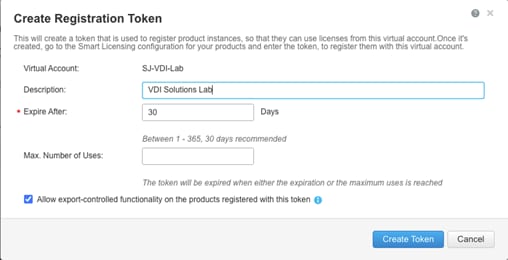
Step 5. Log into the Cisco Intersight portal and click the drop-down list. Click System.
Step 6. Under Cisco Intersight > Licensing, click Register.
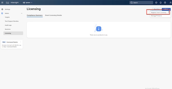
Step 7. Enter the copied token from the Cisco Smart Licensing portal. Click Next.
Step 8. From the drop-down list, select the pre-selected Default Tier * and select the license type (for example, Premier).
Step 9. Select Move All Servers to Default Tier.
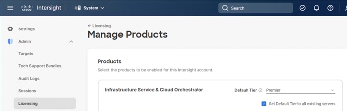
Step 10. Click Proceed.
When the registration is successful (takes a few minutes), the information about the associated Cisco Smart account and default licensing tier selected in the last step is displayed.
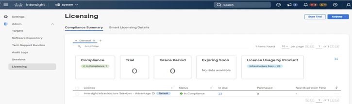
Procedure 4. Set up Cisco Intersight Resource Group
Note: In this procedure, a Cisco Intersight resource group is created where resources such as targets will be logically grouped. In this deployment, a single resource group is created to host all the resources, but you can choose to create multiple resource groups for granular control of the resources.
Step 1. Log into Cisco Intersight.
Step 2. Click Settings (the gear icon) and click Settings.
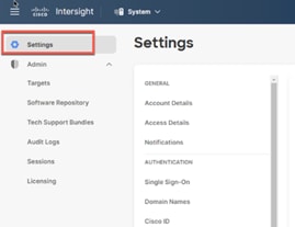
Step 3. Click Resource Groups.
Step 4. Click + Create Resource Group.
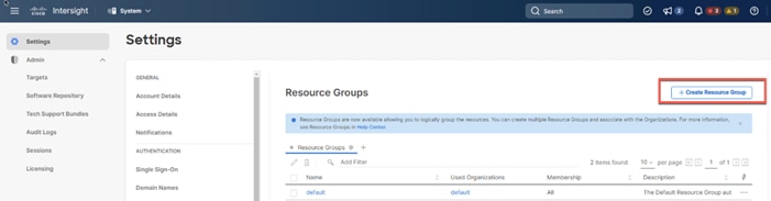
Step 5. Provide a name for the Resource Group (for example, VDI-Lab).
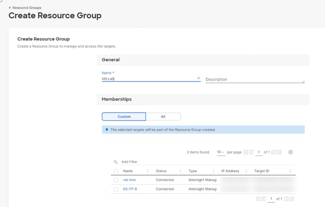
Step 6. Under Memberships, click Custom.
Step 7. Click Create.
Procedure 5. Set up Cisco Intersight Organization
Note: In this procedure, a Cisco Intersight organization is created where all Cisco Intersight managed mode configurations including policies are defined.
Step 1. Log into the Cisco Intersight portal.
Step 2. Click Settings (the gear icon) and select Settings.

Step 3. Click Organizations.
Step 4. Click + Create Organization.
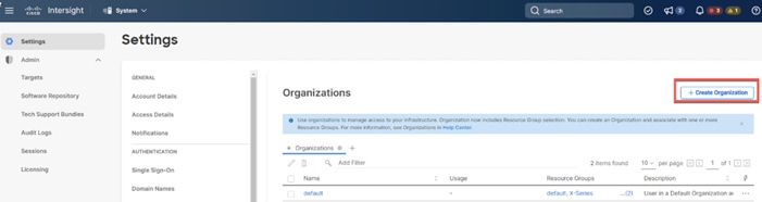
Step 5. Provide a name for the organization (for example, VDI).
Step 6. Select the Resource Group created in the last step (for example, VDI Lab).
Step 7. Click Create.
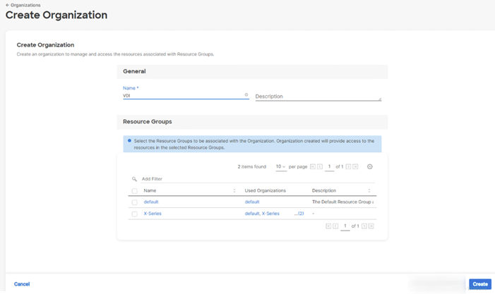
Procedure 6. Claim Cisco UCS Fabric Interconnects in Cisco Intersight
Note: Make sure the initial configuration for the fabric interconnects has been completed. Log into Fabric Interconnect A using a web browser to capture the Cisco Intersight connectivity information.
Step 1. Use the management IP address of Fabric Interconnect A to access the device from a web browser and the previously configured admin password to Log into the device.
Step 2. Under DEVICE CONNECTOR, the current device status will show “Not claimed.” Note, or copy, the Device ID, and Claim Code information for claiming the device in Cisco Intersight.
Step 3. Log into Cisco Intersight.
Step 4. Click Targets.
Step 5. Click Claim New Target.
Step 6. Select Cisco UCS Domain (Intersight Managed) and click Start.
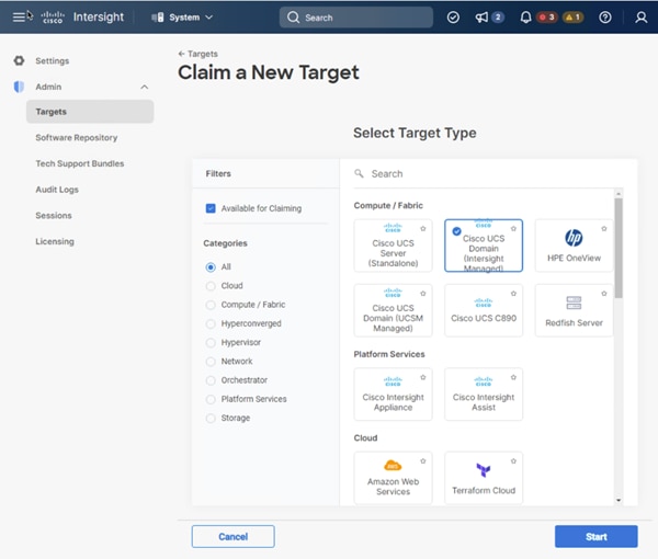
Step 7. Enter the Device ID and Claim Code captured from the Cisco UCS FI.
Step 8. Select the previously created Resource Group and click Claim.
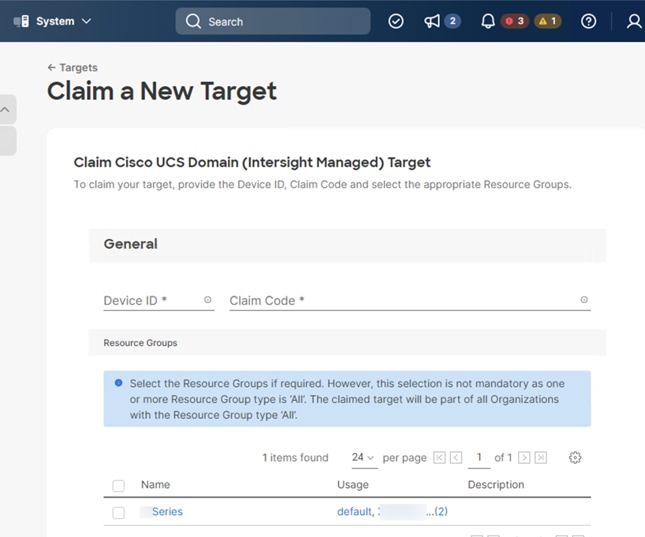
With a successful device claim, Cisco UCS FI appears as a target in Cisco Intersight.
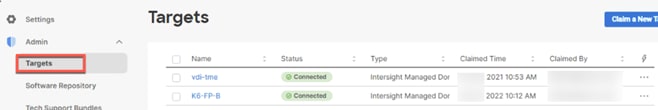
Procedure 7. Verify the addition of Cisco UCS Fabric Interconnects to Cisco Intersight
Step 1. Log back into the web GUI of the Cisco UCS fabric interconnect and click Refresh.
The fabric interconnect status should now be set to Claimed.
Configure a Cisco UCS Domain Profile
This section contains the following procedures:
● Create a Cisco UCS Domain Profile
● Create and apply the VLAN Policy
● Configure the Ports on the Fabric Interconnects
A Cisco UCS domain profile configures a fabric interconnect pair through reusable policies, allows configuration of the ports and port channels, and configures the VLANs in the network. It defines the characteristics of and configured ports on fabric interconnects. The domain-related policies can be attached to the profile either at the time of creation or later. One Cisco UCS domain profile can be assigned to one fabric interconnect domain.
Procedure 1. Create a Cisco UCS Domain Profile
Step 1. Log into the Cisco Intersight portal.
Step 2. From the drop-down list, click Infrastructure Services.
Step 3. Under CONFIGURE in the left pane and click Profiles.
Step 4. In the main window, click UCS Domain Profiles and click Create UCS Domain Profile.
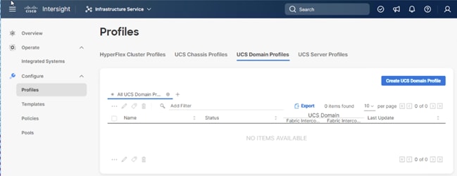
Procedure 2. General Configuration
Step 1. From the drop-down list, select the organization (for example, VDI).
Step 2. Provide a name for the domain profile (for example, VDI-Domain-Profile).
Step 3. Provide an optional Description.
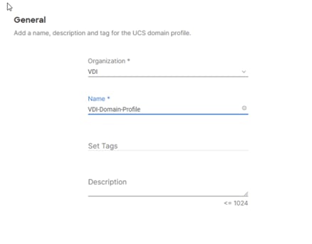
Step 4. Click Next.
Procedure 3. Cisco UCS Domain Assignment
Step 1. To assign the Cisco UCS domain to this new domain profile, click Assign Now and select the previously added Cisco UCS domain (for example, vdi-tme).
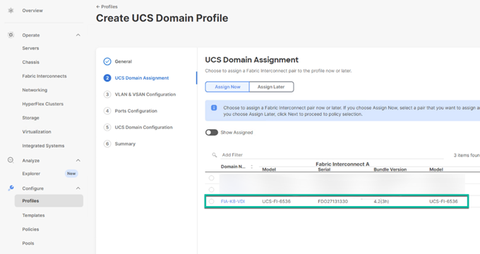
Step 2. Click Next.
Procedure 4. Create and apply the VLAN Policy
Step 1. In this procedure, a single VLAN policy is created for both fabric interconnects
Step 2. Click Select Policy next to VLAN Configuration under Fabric Interconnect A.
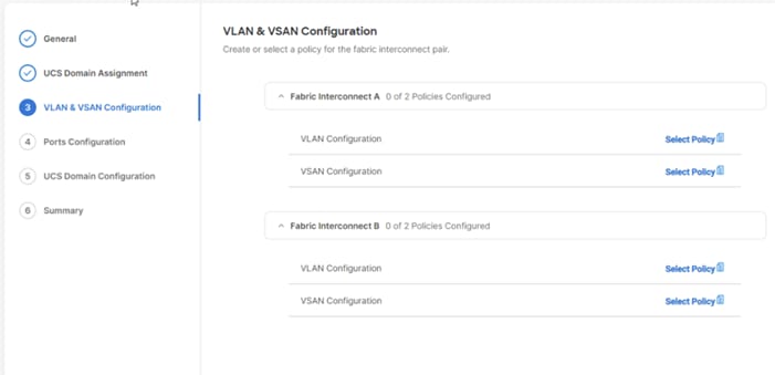
Step 3. Click Create New.
Step 4. Verify correct organization is selected from the drop-down list (for example, default) and provide a name for the policy (for example, VDI-VLAN).
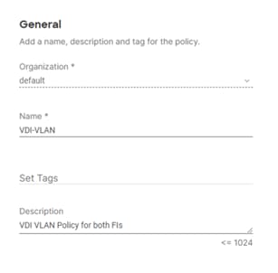
Step 5. Click Next.
Step 6. Click Add VLANs.
Step 7. Provide a name and VLAN ID for the native VLAN.
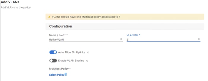
Step 8. Make sure Auto Allow On Uplinks is enabled.
Step 9. To create the required Multicast policy, click Select Policy under Multicast*.
Step 10. In the window on the right, click Create New to create a new Multicast Policy.
Step 11. Provide a Name for the Multicast Policy (for example, VDI-MCAST-Pol).
Step 12. Provide optional Description and click Next.
Step 13. Leave the Snooping State selected and click Create.
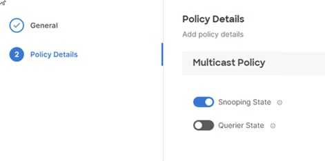
Step 14. Click Add to add the VLAN.
Step 15. Select Set Native VLAN ID and enter the VLAN number (for example, 2) under VLAN ID.
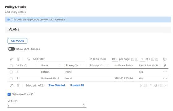
Step 16. Add the remaining VLANs for FlexPod by clicking Add VLANs and entering the VLANs one by one. Reuse the previously created multicast policy for all the VLANs.
The VLANs created during this validation are shown below:
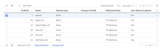
Step 17. Click Create to finish creating the VLAN policy and associated VLANs.
Step 18. Click Select Policy next to VLAN Configuration for Fabric Interconnect B and select the same VLAN policy.
Procedure 5. Configure the Ports on the Fabric Interconnects
Step 1. Click Select Policy for Fabric Interconnect A.
Step 2. Click Create New to define a new port configuration policy.
Note: Use two separate port policies for the fabric interconnects. Using separate policies provide flexibility when port configuration (port numbers or speed) differs between the two FIs.
Step 3. Verify correct organization is selected from the drop-down list (for example, VDI) and provide a name for the policy (for example, VDI-PortPol-A).
Step 4. Click Next to pass the Unified Port page.
Step 5. Click Next to pass the Breakout Options page.
Step 6. Select the ports that need to be configured as server ports by clicking the ports in the graphics (or select from the list below the graphic). When all ports are selected, click Configure.
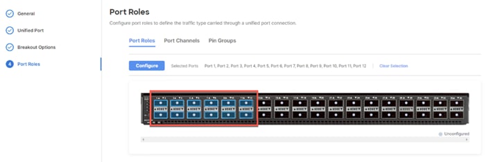
Step 7. From the drop-down list, select Server as the role.
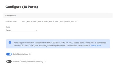
Step 8. Click Save.
Step 9. Configure the Ethernet uplink port channel by selecting the Port Channel in the main pane and then clicking Create Port Channel.
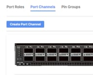
Step 10. Select Ethernet Uplink Port Channel as the role, provide a port-channel ID (for example, 11), and select a value for Admin Speed from drop down menu (for example, Auto).
Note: You can create the Ethernet Network Group, Flow Control, Ling Aggregation or Link control policy for defining disjoint Layer-2 domain or fine tune port-channel parameters. These policies were not used in this deployment and system default values were utilized.
Step 11. Scroll down and select uplink ports from the list of available ports (for example, port 39 )
Step 12. Click Save.
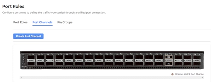
Step 13. Click Save to create the port policy for Fabric Interconnect A.
Note: Use the Summary screen to verify that the ports were selected and configured correctly.
Cisco UCS Domain Configuration
This section contains the following procedures:
● Configure NTP Policy for the Cisco UCS Domain
● Configure Network Connectivity Policy
● Deploy the Cisco UCS Domain Profile
● Verify Cisco UCS Domain Profile Deployment
Note: Under the UCS domain configuration, additional policies can be configured to setup NTP, Syslog, DNS settings, SNMP, QoS and UCS operating mode (end host or switch mode). For this deployment, three policies (NTP, Network Connectivity and System QoS) will be configured.
Procedure 1. Configure NTP Policy for the Cisco UCS Domain
Step 1. Click Select Policy next to NTP and then click Create New.
Step 2. Verify correct organization is selected from the drop-down list (for example, VDI) and provide a name for the policy (for example, VDI-NTPPol).
Step 3. Click Next.
Step 4. Enable NTP, provide the NTP server IP addresses, and select the Timezone from the drop-down list.
Step 5. If required, add a second NTP server by clicking + next to the first NTP server IP address.
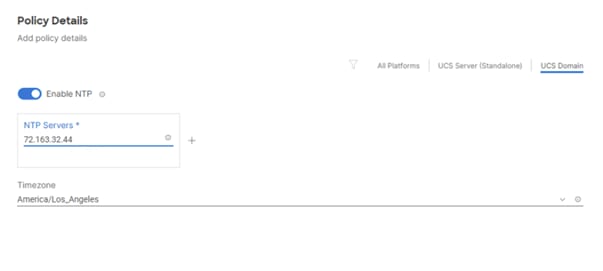
Step 6. Click Create.
Procedure 2. Configure Network Connectivity Policy
Note: To define the Doman Name Service (DNS) servers for Cisco UCS, configure network connectivity policy.
Step 1. Click Select Policy next to Network Connectivity and then click Create New.
Step 2. Verify correct organization is selected from the drop-down list (for example, VDI) and provide a name for the policy (for example, VDI-NetConn-Pol).
Step 3. Provide DNS server IP addresses for Cisco UCS.
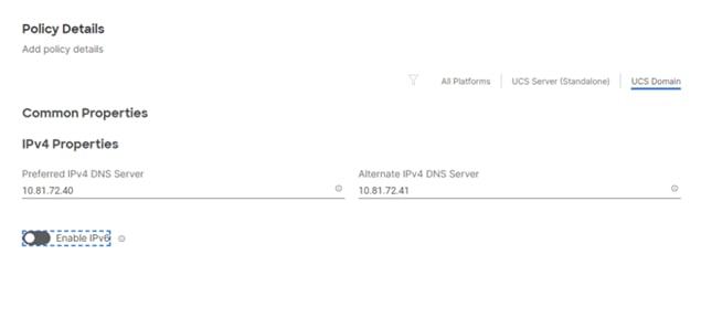
Step 4. Click Create.
Procedure 3. Configure System QoS Policy
To define the QoS settings for Cisco UCS, configure System QoS policy.
Step 1. Click Select Policy next to System QoS* and click Create New.
Step 2. Verify correct organization is selected from the drop-down list (for example, VDI) and provide a name for the policy (for example, VDI-QoSPol).
Step 3. Click Next.
Step 4. Change the MTU for Best Effort class to 9216.
Step 5. Keep the default selections or change the parameters if necessary.
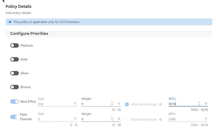
Step 6. Click Create.
Step 7. Click Next.
Step 1. Verify all the settings including the fabric interconnect settings, by expanding the settings and make sure that the configuration is correct.
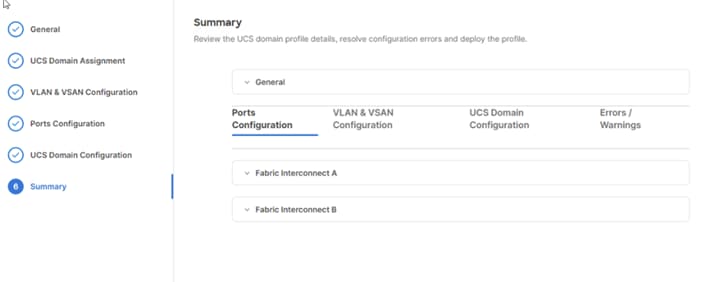
Procedure 5. Deploy the Cisco UCS Domain Profile
Note: After verifying the domain profile configuration, deploy the Cisco UCS profile.
Step 1. From the UCS domain profile Summary view, click Deploy.
Step 2. Acknowledge any warnings and click Deploy again.
Step 3. The system will take some time to validate and configure the settings on the fabric interconnects. Log into the console servers to see when the Cisco UCS fabric interconnects have finished configuration and are successfully rebooted.
Procedure 6. Verify Cisco UCS Domain Profile Deployment
When the Cisco UCS domain profile has been successfully deployed, the Cisco UCS chassis and the Compute Nodes should be successfully discovered.
Note: It takes a while to discover the Compute Nodes for the first time. Watch the number of outstanding tasks in Cisco Intersight:
![]()
Step 1. Log into Cisco Intersight. Under CONFIGURE > Profiles > UCS Domain Profiles, verify that the domain profile has been successfully deployed.
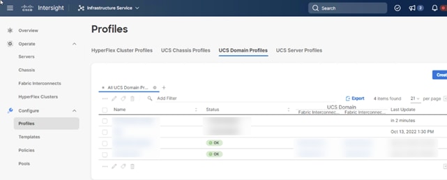
Step 2. Verify that the servers have been successfully discovered and are visible under OPERATE > Servers.
Configure Server Profile Template
This section contains the following procedures:
● Configure a Server Profile Template
● Local Boot Policy and vMedia policy for OS Install
In the Cisco Intersight platform, a server profile enables resource management by simplifying policy alignment and server configuration. The server profiles are derived from a server profile template. The server profile template and its associated policies can be created using the server profile template wizard. After creating server profile template, you can derive multiple consistent server profiles from the template.
Procedure 1. Configure a Server Profile Template
Step 1. Log into Cisco Intersight.
Step 2. Go to CONFIGURE > Templates and click Create UCS Server Profile Template.
Step 3. Select the organization from the drop-down list (for example, VDI).
Step 4. Provide a name for the server profile template. The name used in this deployment is Local-Boot-Template .
Step 5. Click UCS Server (FI-Attached).
Step 6. Provide an optional description.
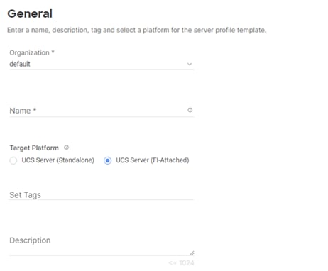
Step 7. Click Next.
Procedure 2. Configure UUID Pool
Step 1. Click Select Pool under UUID Pool and then click Create New.
Step 2. Verify correct organization is selected from the drop-down list (for example, VDI) and provide a name for the UUID Pool (for example, VDI-UUID-Pool).
Step 3. Provide an optional Description and click Next.
Step 4. Provide a UUID Prefix (for example, a random prefix of 33FB3F9C-BF35-4BDE was used).
Step 5. Add a UUID block.
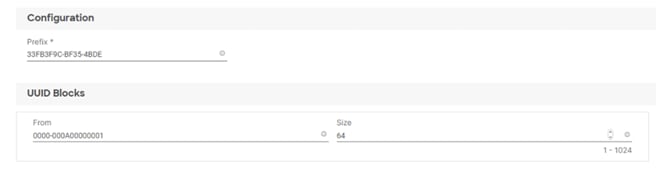
Step 6. Click Create.
Procedure 3. Configure BIOS Policy
Step 1. Click Select Policy next to BIOS and click Create New.
Step 2. Verify correct organization is selected from the drop-down list (for example, VDI) and provide a name for the policy (for example, VDI-BIOSPol).
Step 3. Click Next.
Step 4. From the Policy Details screen, select appropriate values for the BIOS settings. In this deployment, the BIOS values were selected based on recommendations in the performance tuning guide for Cisco UCS M7 BIOS: https://www.cisco.com/c/en/us/products/collateral/servers-unified-computing/ucs-b-series-Compute Node-servers/performance-tuning-guide-ucs-M7-servers.html.
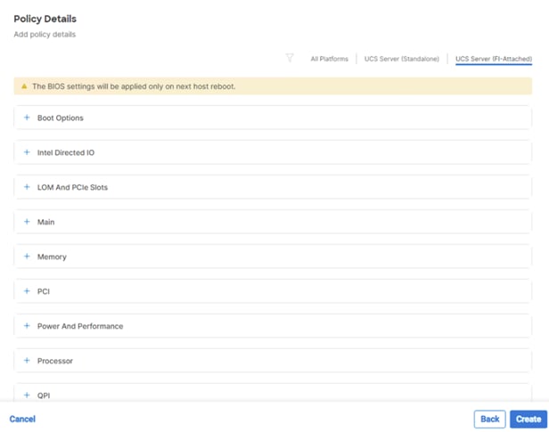
● LOM and PCIe Slot > CDN Support for LOM: Enabled
● Processor > Enhanced CPU performance: Auto
● Memory > NVM Performance Setting: Balanced Profile
Step 5. Click Create.
Procedure 4. Local Boot Policy and vMedia policy for OS Install
Step 1. Click Select Policy next to Boot Order and click Create New.
Step 2. Verify correct organization is selected from the drop-down list (for example, VDI) and provide a name for the policy (for example, VDI-LocalBoot or M7-Local).
Step 3. Select UEFI for Boot Mode.
Step 4. Enable the ‘Enable Secure Boot’ toggle button.
Step 5. From the drop-down list, add two Boot Devices. (Local Disk and Virtual Media)
Step 6. Under Local Disk label it M2 and type MSTOR-RAID by Slot.
Step 7. Under Virtual Media name it dvd and select KVM MAPPED DVD for the Sub-Type.
Step 8. Click Next.
Step 9. Click Next to move to Management Configuration.
This section contains the following procedures:
● Configure Cisco IMC Access Policy
● Configure IPMI Over LAN Policy
● Create MAC Address Pool for Fabric A and B
● Create Ethernet Network Group Policy for a vNIC
● Create Ethernet Network Control Policy
● Create Ethernet Adapter Policy
The following policies will be added to the management configuration:
● IMC Access to define the pool of IP addresses for compute node KVM access
● IPMI Over LAN to allow Intersight to manage IPMI messages
● Local User to provide local administrator to access KVM
Procedure 1. Configure Cisco IMC Access Policy
Step 1. Click Select Policy and then click Create New.
Step 2. Verify correct organization is selected from the drop-down list (for example, VDI) and provide a name for the policy (for example, VDI-IMC-Access).
Step 3. Click Next.
Note: You can select in-band management access to the compute node using an in-band management VLAN (for example, VLAN 30) or out-of-band management access via the Mgmt0 interfaces of the FIs. KVM Policies like SNMP, vMedia and Syslog are currently not supported via Out-Of-Band and will require an In-Band IP to be configured. Since these policies were not configured in this deployment, out-of-band management access was configured so that KVM access to compute nodes is not impacted by any potential switching issues in the fabric.
Step 4. Click UCS Server (FI-Attached).
Step 5. Enable Out-Of-Band Configuration.
Step 6. Under IP Pool, click Select IP Pool and then click Create New.
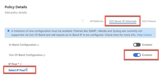
Step 7. Verify the correct organization is selected from the drop-down list (for example, VDI) and provide a name for the policy (for example, VDI-IMC-OOB-Pool).
Step 8. Select Configure IPv4 Pool and provide the information to define a pool for KVM IP address assignment including an IP Block.
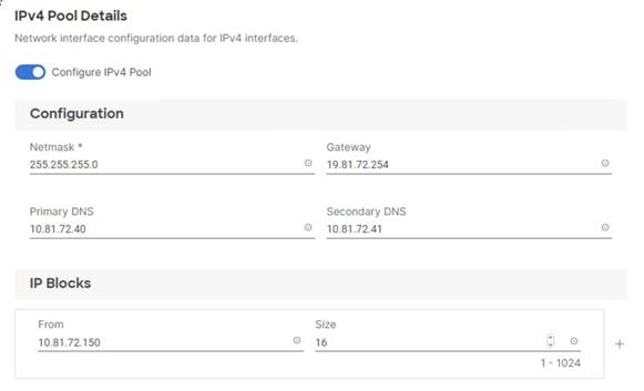
Note: The management IP pool subnet should be accessible from the host that is trying to open the KVM connection. In the example shown here, the hosts trying to open a KVM connection would need to be able to route to 10.81.72.0/24 subnet.
Step 9. Click Next.
Step 10. Deselect Configure IPv6 Pool.
Step 11. Click Create to finish configuring the IP address pool.
Step 12. Click Create to finish configuring the IMC access policy.
Procedure 2. Configure IPMI Over LAN Policy
Step 1. Click Select Policy and then click Create New.
Step 2. Verify correct organization is selected from the drop-down list (for example, VDI) and provide a name for the policy (for example, Enable-IPMIoLAN).
Step 3. Turn on Enable IPMI Over LAN.
Step 4. Click Create.
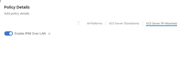
Procedure 3. Configure Local User Policy
Step 1. Click Select Policy and click Create New.
Step 2. Verify correct organization is selected from the drop-down list (for example, VDI) and provide a name for the policy (for example, VDI-LocalUser-Pol).
Step 3. Verify that UCS Server (FI-Attached) is selected.
Step 4. Verify that Enforce Strong Password is selected.
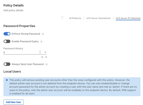
Step 5. Click Add New User and then click + next to the New User
Step 6. Provide the username (for example, fpadmin), choose a role for example, admin), and provide a password.
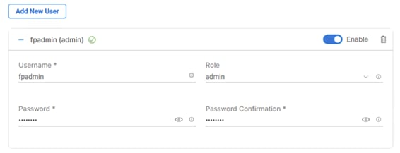
Note: The username and password combination defined here will be used to log into KVMs. The typical Cisco UCS admin username and password combination cannot be used for KVM access.
Step 7. Click Create to finish configuring the user.
Step 8. Click Create to finish configuring local user policy.
Step 9. Click Next to move to Storage Configuration.
Procedure 4. Storage Configuration
Note: Since we configured the M2 local storage in the “Boot Order” section, we did not need to configure a SAN Connectivity policy. Local datastores will be file based using NFS and the OS will be local to M2 cards.
Note: In this CVD we installed the ESXi operating system onto locally installed M2 cards.
Procedure 5. Network Configuration
Step 1. Go to Network Configuration > LAN Connectivity.
The LAN connectivity policy defines the connections and network communication resources between the server and the LAN. This policy uses pools to assign MAC addresses to servers and to identify the vNICs that the servers use to communicate with the network. For iSCSI hosts, this policy also defined an IQN address pool.
For consistent vNIC placement, manual vNIC placement is utilized.
Step 2. Click Select Policy and then click Create New.
Step 3. Verify correct organization is selected from the drop-down list (for example, VDI) and provide a name for the policy (for example, VDI-ESXi-LanConn). Click Next.
Step 4. Under vNIC Configuration, select Manual vNICs Placement.
Step 5. Click Add vNIC.
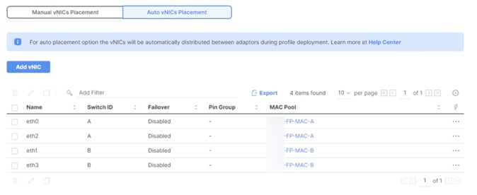
Procedure 6. Create MAC Address Pool for Fabric A and B
When creating the first vNIC, the MAC address pool has not been defined yet, therefore a new MAC address pool will need to be created. Two separate MAC address pools are configured for each Fabric. FP-MAC-A will be reused for all Fabric-A vNICs, and FP-MAC-B will be reused for all Fabric-B vNICs.
Table 15. MAC Address Pools
| Pool Name |
Starting MAC Address |
Size |
vNICs |
| FP-MAC-Pool-A |
00:25:B5:17:0A:00 |
64* |
eth0-eth2 |
| FP-MAC-Pool-B |
00:25:B5:17:0B:00 |
64* |
eth1, eth3 |
Note: Each server requires 2 MAC addresses from the pool. Adjust the size of the pool according to your requirements.
Step 1. Click Select Pool and then click Create New.
Step 2. Verify correct organization is selected from the drop-down list (for example, VDI) and provide a name for the pool from Table 15 depending on the vNIC being created (for example, FP-MAC-A for Fabric A).
Step 3. Click Next.
Step 4. Provide the starting MAC address from Table 15 (for example, 00:25:B5:17:0A:00).
Note: For troubleshooting FlexPod, some additional information is always coded into the MAC address pool. For example, in the starting address 00:25:B5:17:0A:00, 17 is the rack ID and 0A indicates Fabric A.
Step 5. Provide the size of the MAC address pool from Table 15 (for example, 64).
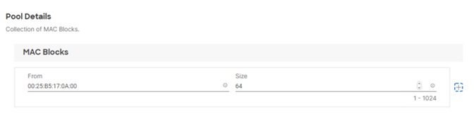
Step 6. Click Create to finish creating the MAC address pool.
Step 7. From the Add vNIC window, provide vNIC Name, Slot ID, Switch ID, and PCI Order information from Table 15.
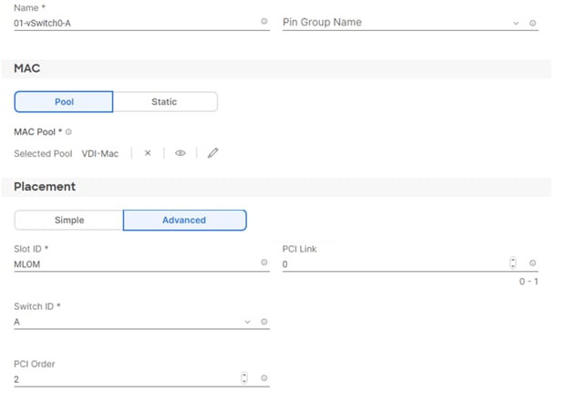
Step 8. For Consistent Device Naming (CDN), from the drop-down list select vNIC Name.
Step 9. Verify that Failover is disabled because the failover will be provided by attaching multiple NICs to the VMware vSwitch and VDS.
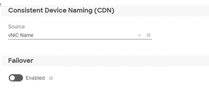
Procedure 7. Create Ethernet Network Group Policy for a vNIC
The Ethernet Network Group policies will be created and reused on applicable vNICs as explained below. The Ethernet Network Group policy defines the VLANs allowed for a particular vNIC, therefore multiple network group policies will be defined for this deployment as follows:
Table 16. Ethernet Group Policy Values
| Group Policy Name |
Native VLAN |
Apply to vNICs |
VLANs |
| VDI-VDS0-NetGrp |
Native-VLAN (2) |
03-VDS0-A, 04-VDS0-B |
VM Traffic, vMotion |
Step 1. Click Select Policy under Ethernet Network Group Policy and then click Create New.
Step 2. Verify correct organization is selected from the drop-down list (for example, VDI) and provide a name for the policy from Table 16 (for example, VDI-vSwitch0-NetGrp).
Step 3. Click Next.
Step 4. Enter the allowed VLANs from Table 6 (for example, 30-36) and the native VLAN ID from Table 6 (for example, 2).
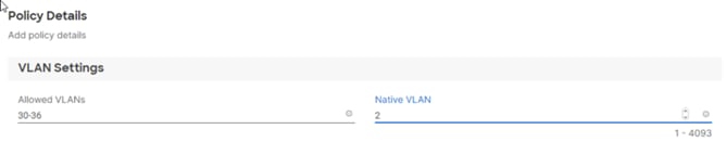
Step 5. Click Create to finish configuring the Ethernet network group policy.
Note: When ethernet group policies are shared between two vNICs, the ethernet group policy only needs to be defined for the first vNIC. For subsequent vNIC policy mapping, click Select Policy and select the previously defined ethernet group policy from the list.
Procedure 8. Create Ethernet Network Control Policy
The Ethernet Network Control Policy is used to enable Cisco Discovery Protocol (CDP) and Link Layer Discovery Protocol (LLDP) for the vNICs. A single policy will be created and reused for all the vNICs.
Step 1. Click Select Policy under Ethernet Network Control Policy and then click Create New.
Step 2. Verify correct organization is selected from the drop-down list (for example, VDI) and provide a name for the policy (for example, VDI-Enable-CDP-LLDP).
Step 3. Click Next.
Step 4. Enable Cisco Discovery Protocol and both Enable Transmit and Enable Receive under LLDP.
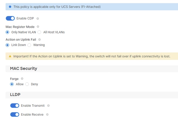
Step 5. Click Create to finish creating Ethernet network control policy.
Procedure 9. Create Ethernet QoS Policy
The ethernet QoS policy is used to enable jumbo maximum transmission units (MTUs) for all the vNICs. A single policy will be created and reused for all the vNICs.
Step 1. Click Select Policy under Ethernet QoS and click Create New.
Step 2. Verify correct organization is selected from the drop-down list (for example, VDI) and provide a name for the policy (for example, VDI-EthQos-Pol).
Step 3. Click Next.
Step 4. Change the MTU, Bytes value to 9000.
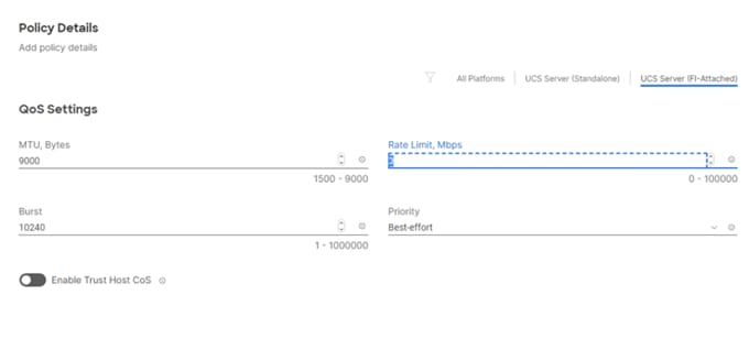
Step 5. Click Create to finish setting up the Ethernet QoS policy.
Procedure 10. Create Ethernet Adapter Policy
The ethernet adapter policy is used to set the interrupts and the send and receive queues. The values are set according to the best-practices guidance for the operating system in use. Cisco Intersight provides default VMware Ethernet Adapter policy for typical VMware deployments.
Optionally, you can configure a tweaked ethernet adapter policy for additional hardware receive queues handled by multiple CPUs in scenarios where there is a lot of vMotion traffic and multiple flows. In this deployment, a modified ethernet adapter policy, VDI-VMware-High-Traffic, is created and attached to the 03-VDS0-A and 04-VDS0-B interfaces which handle vMotion.
Table 17. Ethernet Adapter Policy association to vNICs
| Policy Name |
vNICs |
| VDI-EthAdapter-VMware |
VDI-VDS0-NetGrp |
| VDI-VMware-High-Traffic |
NFS, vMotion |
Step 1. Click Select Policy under Ethernet Adapter and then click Create New.
Step 2. Verify correct organization is selected from the drop-down list (for example, VDI) and provide a name for the policy (for example, VDI-EthAdapter-VMware).
Step 3. Click Select Default Configuration under Ethernet Adapter Default Configuration.
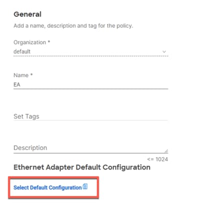
Step 4. From the list, select VMware.
Step 5. Click Next.
Step 6. For the VDI-EthAdapter-VMware policy, click Create and skip the rest of the steps in this section.
Step 7. For the optional VDI-VMware-High-Traffic policy (for VDS interfaces), make the following modifications to the policy:
● Increase Interrupts to 11
● Increase Receive Queue Count to 8
● Increase Completion Queue Count to 9
● Enable Receive Side Scaling
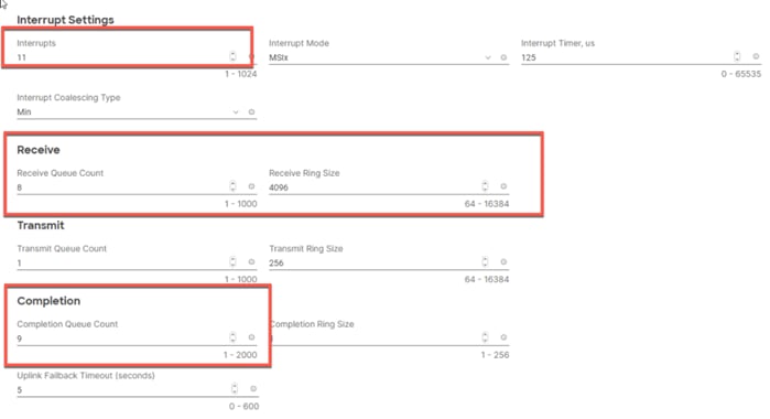
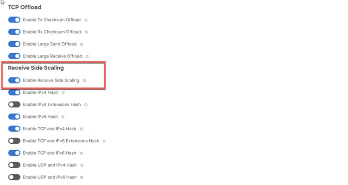
Step 8. Click Create.
Step 9. Click Create to finish creating the vNIC.
Step 10. Go back to Step 1 and repeat vNIC creation for all four vNICs.
Step 11. Verify all four vNICs were successfully created.
Step 12. Click Create to finish creating the LAN Connectivity policy for hosts.
Step 1. When the LAN connectivity policy is created, click Next to move to the Summary screen.
Step 2. On the summary screen, verify policies mapped to various settings. The screenshots below provide summary view for a Local M.2 boot server profile template.
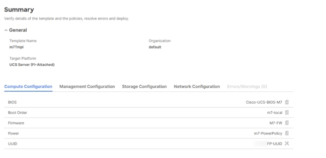
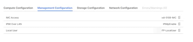
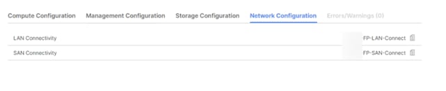
Procedure 12. Derive Server Profile
Step 1. From the Server profile template Summary screen, click Derive Profiles.
Note: This action can also be performed later by navigating to Templates, clicking “…” next to the template name and selecting Derive Profiles.
Step 2. Under the Server Assignment, select Assign Now and click Cisco UCSX 210c M7. You can select one or more servers depending on the number of profiles to be deployed.
Step 3. Click Next.
Note: Cisco Intersight will fill the default information for the number of servers selected.
Step 4. Adjust the Prefix and number if needed.
Step 5. Click Next.
Step 6. Verify the information and click Derive to create the Server Profiles.
Step 7. Cisco Intersight will start configuring the server profiles and will take some time to apply all the policies. Use the Requests tab to see the progress.
![]()
Step 8. When the Server Profiles are deployed successfully, they will appear under the Server Profiles with the status of OK.
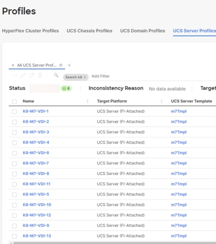
Install VMware ESXi 8.0 U1
This chapter contains the following:
This section contains the following procedures:
● Download ESXi 8.0 U1 from VMware
● Log into the Cisco UCS Environment using Cisco Intersight
● Install VMware ESXi to the Bootable M.2 card of the Hosts
● Set Up Management Networking for ESXi Hosts
● Install VMware and Cisco VIC Drivers for the ESXi Host
● Log into the First VMware ESXi Host by Using VMware Host Client
● Set Up VMkernel Ports and Virtual Switch for ESXi Host VM-Host-Infra-01
● Mount Required Datastores on ESXi Host VM-Host-Infra-01
● Configure NTP on First ESXi Host on ESXi Host VM-Host-Infra-01
● Configure ESXi Host Swap on ESXi Host VM-Host-Infra-01
● Configure Host Power Policy on ESXi Host VM-Host-Infra-01
This section provides detailed instructions for installing VMware ESXi 8.0 U1 in a FlexPod environment. After the procedures are completed, three booted ESXi hosts will be provisioned.
Several methods exist for installing ESXi in a VMware environment. These procedures focus on how to use the built-in keyboard, video, mouse (KVM) console and virtual media features in Cisco Intersight to map remote installation media to individual servers and connect to their boot logical unit numbers (LUNs).
Procedure 1. Download ESXi 8.0 U1 from VMware
Step 1. Click the following link: Cisco Custom ISO for UCS 4.3.1a. You will need a user id and password on vmware.com to download this software, https://customerconnect.vmware.com/downloads/details?downloadGroup=OEM-ESXI80U1-CISCO&productId=1345.
Note: The Cisco Custom ISO for UCS 4.3.1a should also be used for Cisco UCS software release 4.2.(3g) and VMware vSphere 8.0 U1.
Step 2. Download the .iso file.
Procedure 2. Log into the Cisco UCS Environment using Cisco Intersight
Cisco Intersight IP KVM enables the administrator to begin the installation of the operating system (OS) through remote media. It is necessary to log into Cisco Intersight to run the KVM.
Step 1. Open Intersight
Step 2. Click ‘Servers’ to find the target server.
Step 3. Click the triple dots (…) to the right of the target and Select ‘Launch KVM’
Step 4. Click ‘Launch’ and ‘Load KVM Certificate’.
Step 5. In the ‘Virtual Media’ area, click KVM Mapped vDVD and browse to the ESXi custom ISO.
Step 6. In the Boot Device area select KVM Mapped vDVD and reset the server.
Step 7. Boot from Cisco Custom ISO
Procedure 3. Install VMware ESXi to the Bootable M.2 card of the Hosts
Step 1. Boot the server by selecting Boot Server in the KVM and click OK, then click OK again.
On boot, the machine detects the presence of the ESXi installation media and loads the ESXi installer.
Step 2. If the ESXi installer fails to load because the software certificates cannot be validated, reset the server, and when prompted, press F2 to go into BIOS and set the system time and date to current. Now the ESXi installer should load properly.
Step 3. After the installer is finished loading, press Enter to continue with the installation.
Step 4. Read and accept the end-user license agreement (EULA). Press F11 to accept and continue.
Note: It may be necessary to map function keys as User Defined Macros under the Macros menu in the Cisco UCS KVM console.
Step 5. Select the M.2 card that was previously set up for the installation disk for ESXi and press Enter to continue with the installation.
Step 6. Select the appropriate keyboard layout and press Enter.
Step 7. Enter and confirm the root password and press Enter.
Step 8. The installer issues a warning that the selected disk will be repartitioned. Press F11 to continue with the installation.
Step 9. After the installation is complete, press Enter to reboot the server.
Note: The ESXi installation image will be automatically unmapped in the KVM when Enter is pressed.
Step 10. In Cisco Intersight, bind the current service profile to the non-vMedia service profile template to prevent mounting the ESXi installation iso over HTTP.
Procedure 4. Set Up Management Networking for ESXi Hosts
Note: Adding a management network for each VMware host is necessary for managing the host.
Step 1. After the server has finished rebooting, in the UCS KVM console, press F2 to customize VMware ESXi.
Step 2. Log in as root, enter the corresponding password, and press Enter to log in.
Step 3. Use the down arrow key to select Troubleshooting Options and press Enter.
Step 4. Select Enable ESXi Shell and press Enter.
Step 5. Select Enable SSH and press Enter.
Step 6. Press Esc to exit the Troubleshooting Options menu.
Step 7. Select the Configure Management Network option and press Enter.
Step 8. Select Network Adapters and press Enter.
Step 9. Verify that the numbers in the Hardware Label field match the numbers in the Device Name field. If the numbers do not match, note the mapping of vmnic ports to vNIC ports for later use.
Step 10. Using the spacebar, select vmnic1.
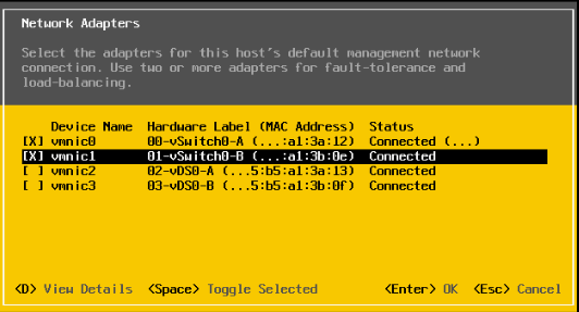
Note: In lab testing, examples were seen where the vmnic and device ordering do not match. In this case, use the Consistent Device Naming (CDN) to note which vmnics are mapped to which vNICs and adjust the upcoming procedure accordingly.
Step 11. Press Enter.
Step 12. Select the VLAN (Optional) option and press Enter.
Step 13. Enter the <ib-mgmt-vlan-id> and press Enter.
Step 14. Select IPv4 Configuration and press Enter.
Step 15. Select the “Set static IPv4 address and network configuration” option by using the arrow keys and space bar.
Step 16. Move to the IPv4 Address field and enter the IP address for managing the ESXi host.
Step 17. Move to the Subnet Mask field and enter the subnet mask for the ESXi host.
Step 18. Move to the Default Gateway field and enter the default gateway for the ESXi host.
Step 19. Press Enter to accept the changes to the IP configuration.
Step 20. Select the IPv6 Configuration option and press Enter.
Step 21. Using the spacebar, select Disable IPv6 (restart required) and press Enter.
Step 22. Select the DNS Configuration option and press Enter.
Note: Since the IP address is assigned manually, the DNS information must also be entered manually.
Step 23. Using the spacebar, select “Use the following DNS server addresses and hostname.”
Step 24. Move to the Primary DNS Server field and enter the IP address of the primary DNS server.
Step 25. Optional: Move to the Alternate DNS Server field and enter the IP address of the secondary DNS server.
Step 26. Move to the Hostname field and enter the fully qualified domain name (FQDN) for the ESXi host.
Step 27. Press Enter to accept the changes to the DNS configuration.
Step 28. Press Esc to exit the Configure Management Network submenu.
Step 29. Press Y to confirm the changes and reboot the ESXi host.
Procedure 5. Install VMware and Cisco VIC Drivers for the ESXi Host
Step 1. Download the offline bundle for the Cisco UCS Tools Component and the NetApp NFS Plug-in for VMware VAAI to the Management workstation: Cisco UCS Tools Component for ESXi 8.0 U1 1.3.1 (ucs-tool-esxi_1.3.1-1OEM.zip) (NetAppNasPluginV2.0.1.zip )
Note: This document describes using the driver versions shown above along with Cisco VIC nenic version 2.0.10.0 along with VMware vSphere version 8.0 U1.U3, Cisco UCS version 5.2(0.230041), and the latest patch NetApp ONTAP 9.13.1P3. These were the versions validated and supported at the time this document was published. This document can be used as a guide for configuring future versions of software. Consult the Cisco UCS Hardware Compatibility List and the NetApp Interoperability Matrix Tool to determine supported combinations of firmware and software.
Step 1. Using an SCP program such as WinSCP, copy the two offline bundles referenced above to the /tmp directory on each ESXi host.
Step 2. Using a ssh tool such as PuTTY, ssh to each VMware ESXi host. Log in as root with the root password.
Step 3. Type cd /tmp.
Step 4. Run the following commands on each host:
esxcli software component apply -d /tmp/ucs-tool-esxi_1.3.1-1OEM.zip
esxcli software vib install -d /tmp/NetAppNasPlugin2.0.1.zip
reboot
Step 5. After reboot, log back into each host and run the following commands and ensure the correct version is installed:
esxcli software component list | grep ucs
esxcli software vib list | grep NetApp
Procedure 7. Log into the First VMware ESXi Host by Using VMware Host Client
Step 1. Open a web browser on the management workstation and navigate to the VM-Host-Infra-01 management IP address.
Step 2. Enter root for the username.
Step 3. Enter the root password.
Step 4. Click Login to connect.
Step 5. Decide whether to join the VMware Customer Experience Improvement Program and click OK.
Procedure 8. Set Up VMkernel Ports and Virtual Switch for ESXi Host VM-Host-Infra-01
Note: In this procedure, you’re setting up only the first ESXi host. The second and third hosts will be added to vCenter and setup from the vCenter HTML5 Interface.
Step 1. From the Host Client Navigator, click Networking.
Step 2. In the center pane, click the Virtual switches tab.
Step 3. Highlight the vSwitch0 line.
Step 4. Click Edit settings.
Step 5. Change the MTU to 9000.
Step 6. Expand NIC teaming.
Step 7. In the Failover order section, click vmnic1 and click Mark active.
Step 8. Verify that vmnic1 now has a status of Active.
Step 9. Click Save.
Step 10. Click Networking, then click the Port groups tab.
Step 11. In the center pane, right-click VM Network and click Edit settings.
Step 12. Name the port group IB-MGMT Network and enter <ib-mgmt-vlan-id> in the VLAN ID field.
Step 13. Click Save to finalize the edits for the IB-MGMT Network.
Step 14. Click the VMkernel NICs tab.
Step 15. Click Add VMkernel NIC.
Step 16. For New port group, enter VMkernel-Infra-NFS.
Step 17. For Virtual switch, click vSwitch0.
Step 18. Enter <infra-nfs-vlan-id> for the VLAN ID.
Step 19. Change the MTU to 9000.
Step 20. Click Static IPv4 settings and expand IPv4 settings.
Step 21. Enter the ESXi host Infrastructure NFS IP address and netmask.
Step 22. Leave TCP/IP stack set at Default TCP/IP stack and do not choose any of the Services.
Step 23. Click Create.
Step 24. Click Add VMkernel NIC.
Step 25. For New port group, enter VMkernel-vMotion.
Step 26. For Virtual switch, click vSwitch0.
Step 27. Enter <vmotion-vlan-id> for the VLAN ID.
Step 28. Change the MTU to 9000.
Step 29. Click Static IPv4 settings and expand IPv4 settings.
Step 30. Enter the ESXi host vMotion IP address and netmask.
Step 31. Click the vMotion stack for TCP/IP stack.
Step 32. Click Create.
Step 33. Optionally, create two more vMotion VMkernel NICs to increase the speed of multiple simultaneous vMotion on this solution’s 40 and 50GE vNICs:
b. For New port group, enter VMkernel-vMotion1.
c. For Virtual switch, click vSwitch0.
d. Enter <vmotion-vlan-id> for the VLAN ID.
e. Change the MTU to 9000.
f. Click Static IPv4 settings and expand IPv4 settings.
g. Enter the ESXi host’s second vMotion IP address and netmask.
h. Click the vMotion stack for TCP/IP stack.
i. Click Create.
j. Click Add VMkernel NIC.
k. For New port group, enter VMkernel-vMotion2.
l. For Virtual switch, click vSwitch0.
m. Enter <vmotion-vlan-id> for the VLAN ID.
n. Change the MTU to 9000.
o. Click Static IPv4 settings and expand IPv4 settings.
p. Enter the ESXi host’s third vMotion IP address and netmask.
q. Click the vMotion stack for TCP/IP stack.
r. Click Create.
Step 34. Click the Virtual Switches tab, then vSwitch0. The properties for vSwitch0 VMkernel NICs should be similar to the following example:
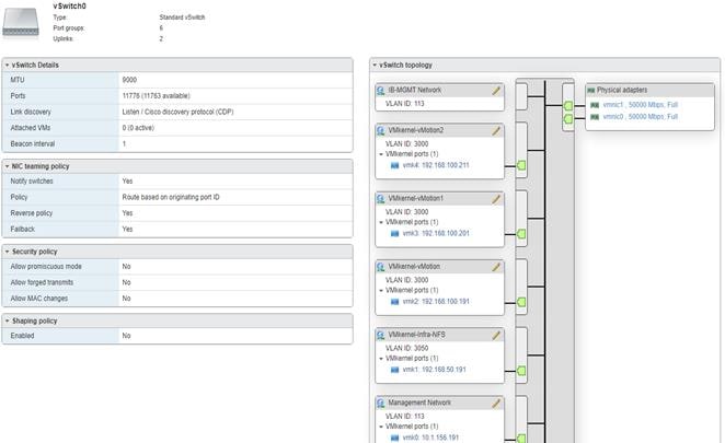
Step 35. Click Networking and the VMkernel NICs tab to confirm configured virtual adapters. The adapters listed should be similar to the following example:
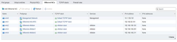
Procedure 9. Mount Required Datastores on ESXi Host VM-Host-Infra-01
Step 1. From the Host Client, click Storage.
Step 2. In the center pane, click the Datastores tab.
Step 3. In the center pane, click New Datastore to add a new datastore.
Step 4. In the New datastore popup, click Mount NFS datastore and click Next.
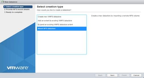
Step 5. Enter infra_datastore for the datastore name. Input the IP address for the nfs-lif-02 LIF for the NFS server. Enter /infra_datastore for the NFS share. Leave the NFS version set at NFS 3. Click Next.
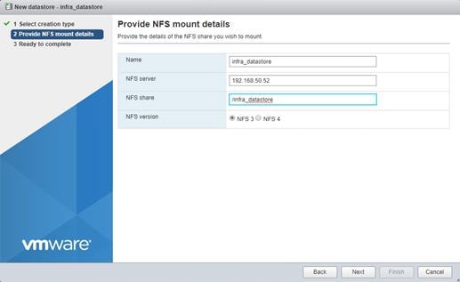
Step 6. Click Finish. The datastore should now appear in the datastore list.
Step 7. In the center pane, click New Datastore to add a new datastore.
Step 8. In the New datastore popup, click Mount NFS datastore and click Next.
Step 9. Enter infra_swap for the datastore name. Enter the IP address for the nfs-lif-01 LIF for the NFS server. Input /infra_swap for the NFS share. Leave the NFS version set at NFS 3. Click Next.
Step 10. Click Finish. The datastore should now appear in the datastore list.
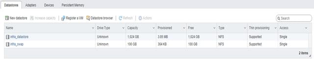
Procedure 10. Configure NTP on First ESXi Host on ESXi Host VM-Host-Infra-01
Step 1. From the Host Client, click Manage.
Step 2. In the center pane, click System > Time and date.
Step 3. Click Edit NTP settings.
Step 4. Select Manually configure the date and time on this host and enter the approximate date and time.
Step 5. Select Use Network Time Protocol (enable NTP client).
Step 6. Use the drop-down list to click Start and stop with host.
Step 7. Enter the two Nexus switch NTP addresses in the NTP servers box separated by a comma.
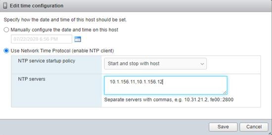
Step 8. Click Save to save the configuration changes.
Note: Currently, it isn’t possible to start NTP from the ESXi Host Client. NTP will be started from vCenter. The NTP server time may vary slightly from the host time.
Procedure 11. Configure ESXi Host Swap on ESXi Host VM-Host-Infra-01
Step 1. From the Host Client, click Manage.
Step 2. In the center pane, click System > Swap.
Step 3. Click Edit settings.
Step 4. Use the drop-down list to click infra_swap. Leave all other settings unchanged.
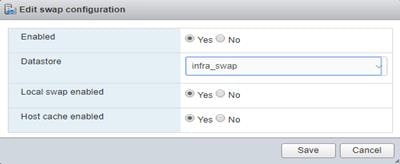
Step 5. Click Save to save the configuration changes.
Procedure 12. Configure Host Power Policy on ESXi Host VM-Host-Infra-01
Note: Implementing this policy is recommended in Performance Tuning Guide for Cisco UCS M5 Servers for maximum VMware ESXi performance. If your organization has specific power policies, please set this policy accordingly.
Step 1. From the Host Client, click Manage.
Step 2. Go to Hardware > Power Management.
Step 3. Click Change policy.
Step 4. Click High performance and click OK.
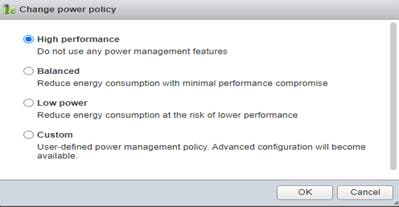
VMware vCenter 8.0 U1
This subject contains the following:
● Build the VMware vCenter Server Appliance
● Set up VMware vCenter Server
Procedure 1. Build the VMware vCenter Server Appliance
Note: The VCSA deployment consists of 2 stages: install and configuration.
Step 1. Locate and copy the VMware-VCSA-all-8.0.1.00300-22088981.iso file to the desktop of the management workstation. This ISO is for the VMware vSphere 8.0 U1 vCenter Server Appliance.
Note: It is important to use at a minimum VMware vCenter release 8.0 U1 to ensure access to all needed features.
Step 2. Using ISO mounting software, mount the ISO image as a disk on the management workstation.
Step 3. In the mounted disk directory, navigate to the vcsa-ui-installer > win32 directory and double-click installer.exe. The vCenter Server Appliance Installer wizard appears.
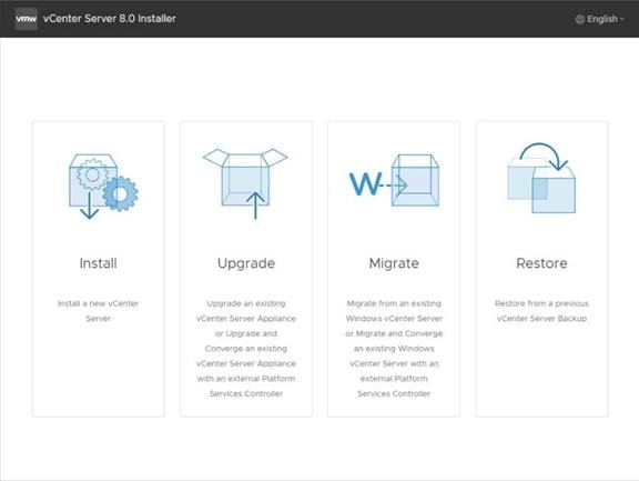
Step 4. Click Install to start the vCenter Server Appliance deployment wizard.
Step 5. Click NEXT in the Introduction section.
Step 6. Read and accept the license agreement and click NEXT.
Step 7. In the “vCenter Server deployment target” window, enter the host name or IP address of the first ESXi host, Username (root) and Password. Click NEXT.
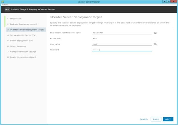
Step 8. Click YES to accept the certificate.
Step 9. Enter the Appliance VM name and password details in the Set up vCenter Server VM section. Click NEXT.
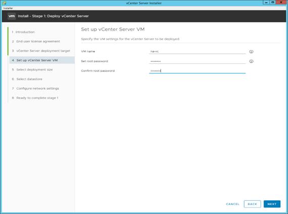
Step 10. In the Select deployment size section, click the Deployment size and Storage size. For example, click Small and Default. Click NEXT.
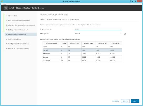
Step 11. Click infra_datastore for storage. Click NEXT.
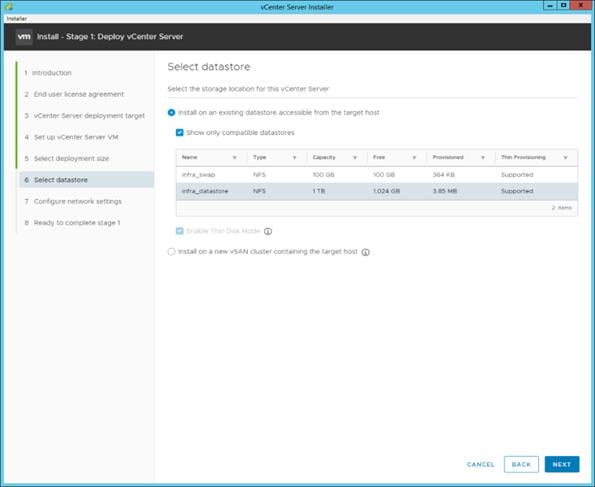
Step 12. In the Network Settings section, configure the following settings:
a. Click a Network: IB-MGMT Network.
Note: It is important that the vCenter VM stay on the IB-MGMT Network on vSwitch0 and that it not get moved to a vDS. If vCenter is moved to a vDS and the virtual environment is completely shut down and then brought back up, and it is attempted to bring up vCenter on a different host than the one it was running on before the shutdown, vCenter will not have a functional network connection. With the vDS, for a virtual machine to move from one host to another, vCenter must be up and running to coordinate the move of the virtual ports on the vDS. If vCenter is down, the port move on the vDS cannot occur correctly. Moving vCenter to a different host on vSwitch0 to be brought up always occurs correctly without requiring vCenter to already be up and running.
b. IP version: IPV4
c. IP assignment: static
d. FQDN: <vcenter-fqdn>
e. IP address: <vcenter-ip>
f. Subnet mask or prefix length: <vcenter-subnet-mask>
g. Default gateway: <vcenter-gateway>
h. DNS Servers: <dns-server1>,<dns-server2>
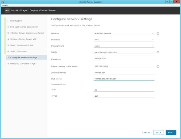
Step 13. Click NEXT.
Step 14. Review all values and click FINISH to complete the installation.
Note: The vCenter Server appliance installation will take a few minutes to complete.
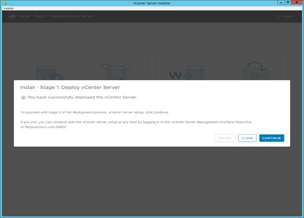
Step 15. Click CONTINUE to proceed with stage 2 configuration.
Step 16. Click NEXT.
Step 17. In the vCenter Server configuration window, configure these settings:
a. Time Synchronization Mode: Synchronize time with NTP servers.
b. NTP Servers: <nexus-a-ntp-ip>,<nexus-b-ntp-ip>
c. SSH access: Enabled.
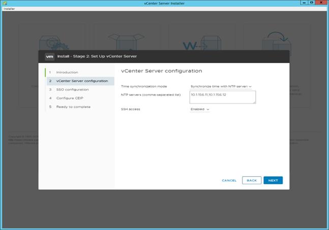
Step 18. Click NEXT.
Step 19. Complete the SSO configuration as shown below or according to your organization’s security policies:
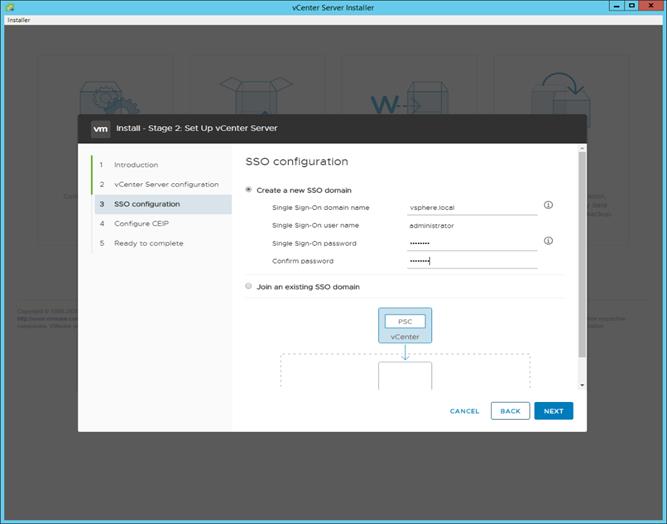
Step 20. Click NEXT.
Step 21. Decide whether to join VMware’s Customer Experience Improvement Program (CEIP).
Step 22. Click NEXT.
Step 23. Review the configuration and click FINISH.
Step 24. Click OK.
Note: The Server setup will take a few minutes to complete.
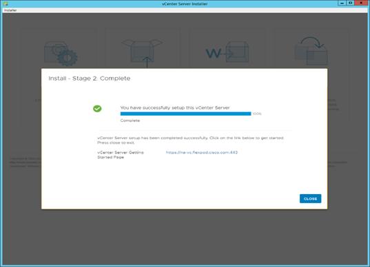
Step 25. Click CLOSE. Eject or unmount the VCSA installer ISO.
Procedure 2. Adjust vCenter CPU settings and resolve Admission Control issues
Note: If a vCenter deployment size Small or Larger was selected in the vCenter setup, it is possible that the VCSA’s CPU setup does not match the Cisco UCS server CPU hardware configuration. Cisco UCS B and C-Series servers are normally 2-socket servers. In this validation, the Small deployment size was selected and vCenter was setup for a 4-socket server. This setup will cause issues in the VMware ESXi cluster Admission Control.
Step 1. Open a web browser on the management workstation and navigate to the VM-Host-Infra-01 management IP address.
Step 2. Enter root for the username.
Step 3. Enter the root password.
Step 4. Click Login to connect.
Step 5. Click Virtual Machines.
Step 6. Right-click the vCenter VM and click Edit settings.
Step 7. In the Edit settings window, expand CPU and check the value of Sockets.
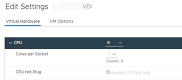
Step 8. If the number of Sockets does not match your server configuration, it will need to be adjusted. Click Cancel.
Step 9. If the number of Sockets needs to be adjusted:
a. Right-click the vCenter VM and click Guest OS > Shut down. Click Yes on the confirmation.
b. Once vCenter is shut down, right-click the vCenter VM and click Edit settings.
c. In the Edit settings window, expand CPU and change the Cores per Socket value to make the Sockets value equal to your server configuration (normally 2).
d. Click Save.
e. Right-click the vCenter VM and click Power > Power on. Wait approximately 10 minutes for vCenter to come up.
Procedure 3. Set up VMware vCenter Server
Step 1. Using a web browser, navigate to https://<vcenter-ip-address>:5480.
Step 2. Log into the VMware vCenter Server Management interface as root with the root password set in the vCenter installation.
Step 3. Click Time.
Step 4. Click EDIT.
Step 5. Select the appropriate Time zone and click SAVE.
Step 6. Click Administration.
Step 7. According to your Security Policy, adjust the settings for the root user and password.
Step 8. Click Update.
Step 9. Follow the prompts to STAGE AND INSTALL any available vCenter updates. In this validation, vCenter version 8.0 U1.2.00500 was installed.
Step 10. Go to root > Logout to logout of the Appliance Management interface.
Step 11. Using a web browser, navigate to https://<vcenter-fqdn>. You will need to navigate security screens.
Note: With VMware vCenter 8.0 U1.U3 the use of the vCenter FQDN is required.
Step 12. Click LAUNCH VSPHERE CLIENT (HTML5).
Note: Although the previous versions of this document used the FLEX vSphere Web Client, the VMware vSphere HTML5 Client is the only option in vSphere 7 and will be used going forward.
Step 13. Log in using the Single Sign-On username (administrator@vsphere.local) and password created during the vCenter installation. Dismiss the Licensing warning at this time.
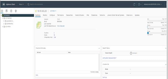
Step 14. Click ACTIONS > New Datacenter.
Step 15. Type “FlexPod-DC” in the Datacenter name field.
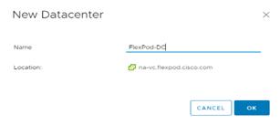
Step 16. Click OK.
Step 17. Expand the vCenter.
Step 18. Right-click the datacenter FlexPod-DC in the list in the left pane. Click New Cluster.
Step 19. Name the cluster FlexPod-Management.
Step 20. Turn on DRS and vSphere HA. Do not turn on vSAN.
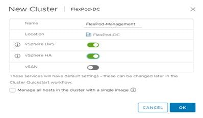
Step 21. Click OK to create the new cluster.
Step 22. Right-click FlexPod-Management and click Settings.
Step 23. Click Configuration > General in the list located and click EDIT.
Step 24. Click Datastore specified by host and click OK.
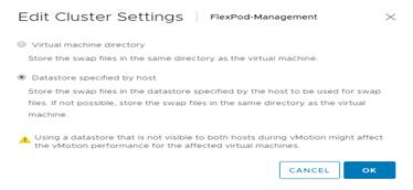
Step 25. Right-click FlexPod-Management and click Add Hosts.
Step 26. In the IP address or FQDN field, enter either the IP address or the FQDN of the first VMware ESXi host. Enter root for the Username and the root password. Click NEXT.
Step 27. In the Security Alert window, click the host and click OK.
Step 28. Verify the Host summary information and click NEXT.
Step 29. Ignore warnings about the host being moved to Maintenance Mode and click FINISH to complete adding the host to the cluster.
Note: The added ESXi host will have warnings that the ESXi Shell and SSH have been enabled. These warnings can be suppressed.
Step 30. In the list, right-click the added ESXi host and click Settings.
Step 31. Under Virtual Machines, click Swap File location.
Step 32. Click EDIT.
Step 33. Click the infra_swap datastore and click OK.
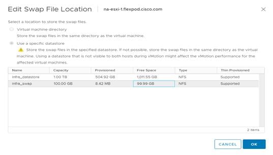
Step 34. Under System, click Time Configuration.
Step 35. Click EDIT. Set the time and date to the correct local time and click OK.
Step 36. Click EDIT.
Step 37. In the Edit Network Time Protocol window, select Enable and then select Start NTP Service. Ensure the other fields are filled in correctly and click OK.
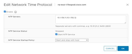
Step 38. Under Hardware, click Overview. Scroll down and ensure the Power Management Active policy is High Performance. If the Power Management Active policy is not High Performance, to the right of Power Management, click EDIT POWER POLICY. Click High performance and click OK.
Finalize the NetApp ONTAP Storage Configuration
This chapter contains the following:
● Configure DNS for infrastructure SVM
● Create and enable auditing configuration for the SVM
● Delete the residual default broadcast domains with ifgroups (Applicable for 2-node cluster only)
This chapter contains the procedures to finalize the NetApp controller configuration.
Note: ONTAP Boot storage setup is not required for this solution as it uses local boot using M.2 drives
Procedure 1. Configure DNS for infrastructure SVM
Step 1. To configure DNS for the Infra-SVM, run the following command:
dns create -vserver <vserver-name> -domains <dns-domain> -nameserve <dns-servers>
Example:
dns create -vserver Infra-SVM -domains flexpodb4.cisco.com -nameservers 10.102.1.151,10.102.1.152
Procedure 2. Create and enable auditing configuration for the SVM
Step 1. To create auditing configuration for the SVM, run the following command:
vserver audit create -vserver Infra-SVM -destination /audit_log
Step 2. Run the following command to enable audit logging for the SVM:
vserver audit enable -vserver Infra-SVM
Note: It is recommended that you enable audit logging so you can capture and manage important support and availability information. Before you can enable auditing on the SVM, the SVM’s auditing configuration must already exist.
Note: If you do not perform the configuration steps for the SVM, you will see a warning in AIQUM stating “Audit Log is disabled.”
Step 1. To delete the residual default broadcast domains that are not in use, run the following commands:
broadcast-domain delete -broadcast-domain <broadcast-domain-name>
broadcast-domain delete -broadcast-domain Default-1
broadcast-domain delete -broadcast-domain Default-2
Note: NetApp AutoSupport sends support summary information to NetApp through HTTPS.
Step 1. Test the AutoSupport configuration by sending a message from all nodes of the cluster:
autosupport invoke -node * -type all -message “FlexPod storage configuration completed”
Configuration and Installation
This chapter contains the following:
● FlexPod Automated Deployment with Ansible
FlexPod Automated Deployment with Ansible
If using the published Ansible playbooks to configure the FlexPod infrastructure, follow the procedures detailed in this section.
Ansible Automation Workflow and Solution Deployment
The Ansible automated FlexPod solution uses a management workstation (control machine) to run Ansible playbooks to configure Cisco Nexus, NetApp ONTAP Storage, Cisco UCS, Cisco MDS, and VMware ESXi.
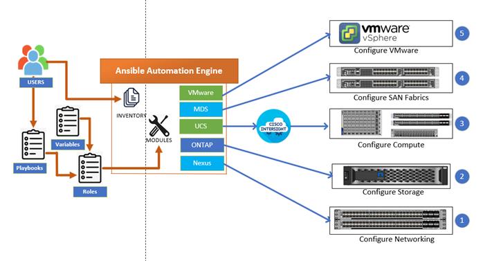
To use the Ansible playbooks demonstrated in this document: Getting Started with Red Hat Ansible, the management workstation must also have a working installation of Git and access to the Cisco DevNet public GitHub repository. The Ansible playbooks used in this document are cloned from the public repositories, located at the following links:
● Cisco DevNet: https://developer.cisco.com/codeexchange/github/repo/ucs-compute-solutions/FlexPod-IMM-VMware/
● GitHub repository for FlexPod infrastructure setup: https://github.com/ucs-compute-solutions/FlexPod-IMM-VMware
● For more information on FlexPod setup using Ansible, go to https://www.cisco.com/c/en/us/td/docs/unified_computing/ucs/UCS_CVDs/flexpod_iac_e2d_deploy.html.
Procedure 5. Update Cisco VIC Drivers for ESXi
Note: When ESXi is installed from Cisco Custom ISO, you might have to update the Cisco VIC drivers for VMware ESXi Hypervisor to match the current Cisco Hardware and Software Interoperability Matrix.
Note: The Cisco-nenic- 2.0.11.0 drivers were used in this Cisco Validated Design.
Step 1. Log into your VMware Account to download required drivers for FNIC and NENIC as per the recommendation.
Step 2. Enable SSH on ESXi to run following commands:
esxcli software vib update -d /path/offline-bundle.zip
The VMware vSphere Client was configured to support the solution and testing environment as follows:
● Datacenter: FlexPod - NetApp Storage AFF A400 with Cisco UCS
● Cluster: FlexPod-VDI - Single-session/Multi-session OS VDA workload
● Infrastructure Cluster: Infrastructure virtual machines (vCenter, Active Directory, DNS, DHCP, SQL Server, Citrix Virtual Apps and Desktops Connection Servers, and other common services), Login VSI launcher infrastructure were connected using the same set of switches.
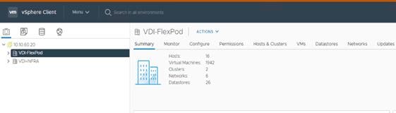
Build the Virtual Machines and Environment for Workload Testing
This chapter contains the following:
● Software Infrastructure Configuration
● Install and Configure Citrix Virtual Apps and Desktops
● Install Citrix Virtual Apps and Desktops Delivery Controller, Citrix Licensing, and StoreFront
● Install and Configure Citrix Provisioning Server 2203
● Install the Citrix Provisioning Server Target Device Software
● Provision Virtual Desktop Machines
● Citrix Virtual Apps and Desktops Policies and Profile Management
● FSLogix for Citrix Virtual Apps and Desktops Profile Management
Create all necessary DHCP scopes for the environment and set the Scope Options.
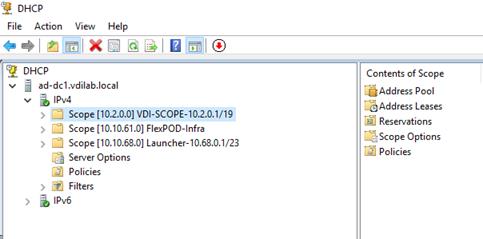
Software Infrastructure Configuration
This section explains how to configure the software infrastructure components that comprise this solution.
Install and configure the infrastructure virtual machines by following the process listed in Table 18.
Table 18. Test Infrastructure Virtual Machine Configuration
| Configuration |
Citrix Virtual Apps and Desktops Controllers Virtual Machines |
Citrix Provisioning Servers Virtual Machines |
| Operating system |
Microsoft Windows Server 2022 |
Microsoft Windows Server 2022 |
| Virtual CPU amount |
6 |
6 |
| Memory amount |
24 GB |
24 GB |
| Network |
VMXNET3 Infra-Mgmt-31 |
VMXNET3 Infra-Mgmt-31 |
| Disk-1 (OS) size |
40 GB |
40 GB |
| Disk-2 size |
- |
200 GB Disk Store |
| Configuration |
Microsoft Active Directory DCs Virtual Machines |
vCenter Server Appliance Virtual Machine |
| Operating system |
Microsoft Windows Server 2022 |
VCSA – SUSE Linux |
| Virtual CPU amount |
4 |
8 |
| Memory amount |
8 GB |
32 GB |
| Network |
VMXNET3 Infra-Mgmt-31 |
VMXNET3 k23-InBand-Mgmt-31 |
| Disk size |
40 GB |
698.84 GB (across 13 VMDKs) |
| Configuration |
Microsoft SQL Server Virtual Machine |
Citrix StoreFront Controller Virtual Machine |
| Operating system |
Microsoft Windows Server 2022 Microsoft SQL Server 2022 |
Microsoft Windows Server 2022 |
| Virtual CPU amount |
8 |
4 |
| Memory amount |
24GB |
8 GB |
| Network |
VMXNET3 Infra-Mgmt-31 |
VMXNET3 Infra-Mgmt-31 |
| Disk-1 (OS) size |
40 GB |
40 GB |
| Disk-2 size |
100 GB SQL Databases\Logs |
- |
This section provides guidance regarding creating the golden (or master) images for the environment. Virtual machines for the master targets must first be installed with the software components needed to build the golden images. Additionally, all available security patches as of October 2021 for the Microsoft operating systems, SQL server and Microsoft Office 2021 were installed.
To prepare Single-session OS or Multi-session OS master virtual machine, there are three major steps: installing the PVS Target Device x64 software (if delivered with Citrix Provisioning Services), installing the Virtual Delivery Agents (VDAs), and installing application software.
Note: For this CVD, the images contain the basics needed to run the Login VSI workload.
The Single-session OS and Multi-session OS master target virtual machines were configured as detailed in Table 19.
Table 19. Single-session OS and Multi-session OS Virtual Machines Configurations
| Configuration |
Single-session OS Virtual Machines |
Multi-session OS Virtual Machines |
| Operating system |
Microsoft Windows 11 64-bit |
Microsoft Windows Server 2021 |
| Virtual CPU amount |
2 |
8 |
| Memory amount |
4 GB |
32 GB |
| Network |
VMXNET3 10_10_34_NET |
VMXNET3 10_10_34_NET |
| Citrix PVS vDisk size Citrix MCS Disk Size |
48 GB (dynamic) 48 GB |
90 GB (dynamic) |
| Write cache Disk size |
6 GB |
6 GB |
| Citrix PVS write cache RAM cache size |
256 MB |
1024 MB |
| Additional software used for testing |
Microsoft Office 2021 Office Update applied Login VSI 4.1.40 Target Software (Knowledge Worker Workload) |
Microsoft Office 2021 Office Update applied Login VSI 4.1.40 Target Software (Knowledge Worker Workload) |
| Additional Configuration |
Configure DHCP Add to domain Install VMWare tool Install .Net 3.5 Activate Office Install VDA Agent Run PVS Imaging Wizard (For non-persistent Desktops only) |
Configure DHCP Add to domain Install VMWare tool Install .Net 3.5 Activate Office Install VDA Agent |
Install and Configure Citrix Virtual Apps and Desktops
This section explains the installation of the core components of the Citrix Virtual Apps and Desktops system. This CVD installs two Citrix Virtual Apps and Desktops Delivery Controllers to support both hosted shared desktops (HSD), non-persistent hosted virtual desktops (HVD), and persistent hosted virtual desktops (HVD).
Citrix recommends that you use Secure HTTP (HTTPS) and a digital certificate to protect vSphere communications. Citrix recommends that you use a digital certificate issued by a certificate authority (CA) according to your organization's security policy. Otherwise, if the security policy allows, use the VMware-installed self-signed certificate.
Procedure 1. Install vCenter Server Self-Signed Certificate
Step 1. Add the FQDN of the computer running vCenter Server to the hosts file on that server, located at SystemRoot/
WINDOWS/system32/Drivers/etc/. This step is required only if the FQDN of the computer running vCenter Server is not already present in DNS.
Step 2. Open Internet Explorer and enter the address of the computer running vCenter Server (for example, https://FQDN as the URL).
Step 3. Accept the security warnings.
Step 4. Click the Certificate Error in the Security Status bar and select View certificates.
Step 5. Click Install certificate, select Local Machine, and then click Next.
Step 6. Select Place all certificates in the following store and then click Browse.
Step 7. Click Show physical stores.
Step 8. Click Trusted People.
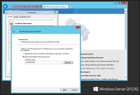
Step 9. Click Next and then click Finish.
Step 10. Repeat steps 1-9 on all Delivery Controllers and Provisioning Servers.
Install Citrix Virtual Apps and Desktops Delivery Controller, Citrix Licensing, and StoreFront
The process of installing the Citrix Virtual Apps and Desktops Delivery Controller also installs other key Citrix Virtual Apps and Desktops software components, including Studio, which is used to create and manage infrastructure components, and Director, which is used to monitor performance and troubleshoot problems.
Note: Dedicated StoreFront and License servers should be implemented for large scale deployments.
Procedure 1. Install Citrix License Server
Step 1. To begin the installation, connect to the first Citrix License server and launch the installer from the Citrix_Virtual_Apps_and_Desktops_7_2203 ISO.
Step 2. Click Start.
Step 3. Click Extend Deployment – Citrix License Server.
Step 4. Read the Citrix License Agreement. If acceptable, indicate your acceptance of the license by selecting the radio button for I have read, understand, and accept the terms of the license agreement.
Step 5. Click Next.
Step 6. Click Next.
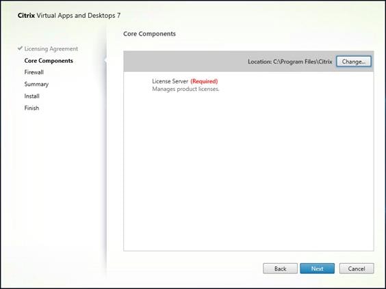
Step 7. Select the default ports and automatically configured firewall rules.
Step 8. Click Next.
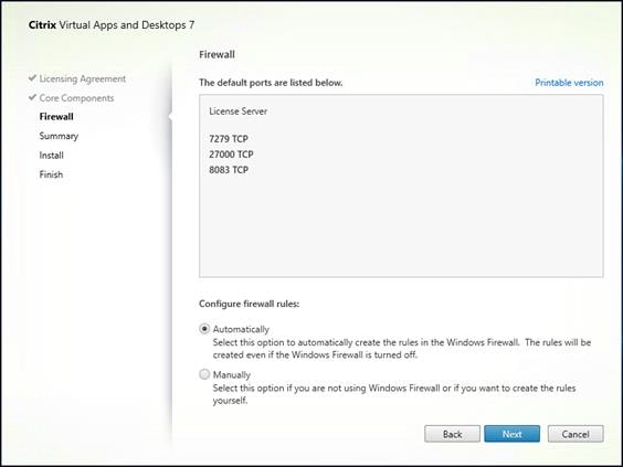
Step 9. Click Install.
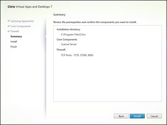
Step 10. Click Finish to complete the installation.
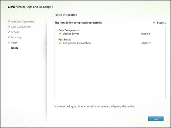
Procedure 2. Install Citrix Licenses
Step 1. Copy the license files to the default location (C:\Program Files (x86)\Citrix\Licensing\ MyFiles) on the license server.
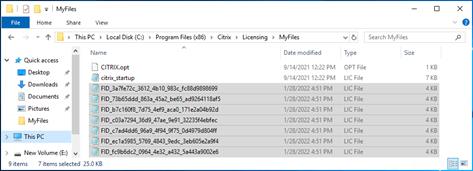
Step 2. Restart the server or Citrix licensing services so that the licenses are activated.
Step 3. Run the application Citrix License Administration Console.
Step 4. Confirm that the license files have been read and enabled correctly.
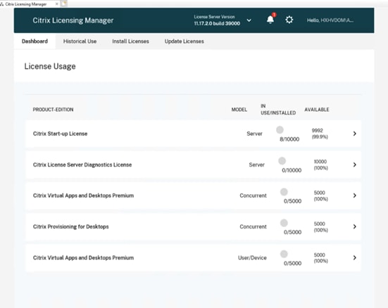
Procedure 3. Install the Citrix Virtual Apps and Desktops
Step 1. To begin the installation, connect to the first Delivery Controller server and launch the installer from the Citrix_Virtual_Apps_and_Desktops_7_2203 ISO.
Step 2. Click Start.
Step 3. The installation wizard presents a menu with three subsections. Click Get Started - Delivery Controller.
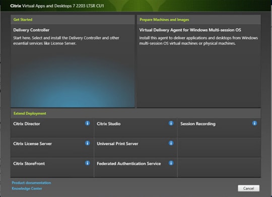
Step 4. Read the Citrix License Agreement. If acceptable, indicate your acceptance of the license by selecting the radio button for I have read, understand, and accept the terms of the license agreement.
Step 5. Click Next.
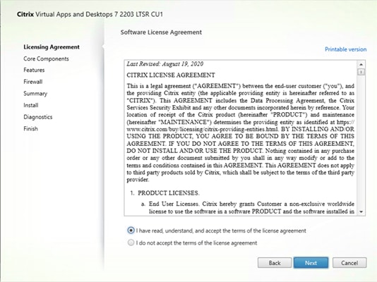
Step 6. Select the components to be installed on the first Delivery Controller Server:
● Delivery Controller
● Studio
● Director
Step 7. Click Next.
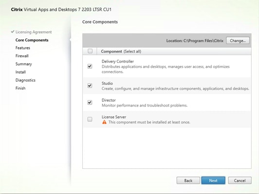
Step 8. Since a dedicated SQL Server will be used to Store the Database, leave “Install Microsoft SQL Server 2014 SP2 Express” unchecked.
Step 9. Click Next.
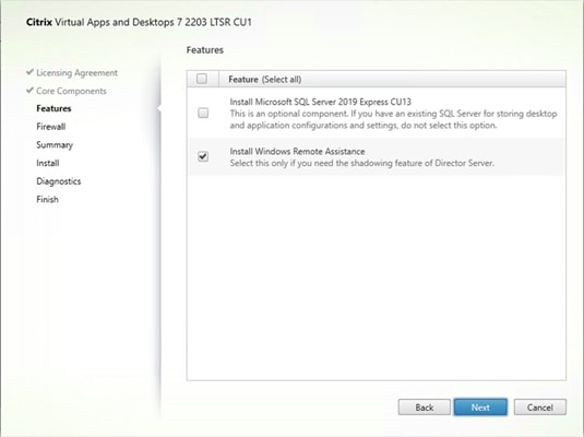
Step 10. Select the default ports and automatically configured firewall rules.
Step 11. Click Next.
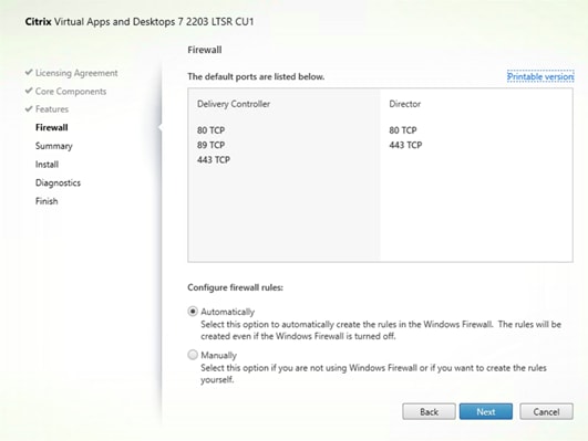
Step 12. Click Finish to begin the installation.
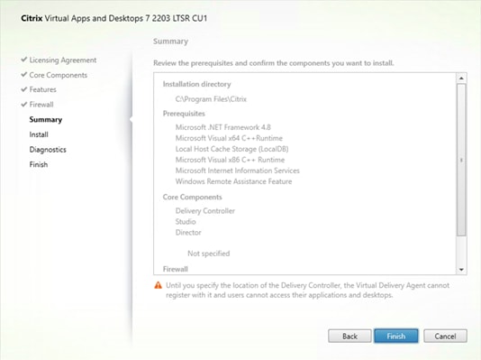
Note: Multiple reboots may be required to finish installation.
Step 13. (Optional) Collect diagnostic information/Call Home participation.
Step 14. Click Next.
Step 15. Click Finish to complete the installation.
Step 16. (Optional) Check Launch Studio to launch Citrix Studio Console.
Procedure 4. Additional Delivery Controller Configuration
Note: After the first controller is completely configured and the Site is operational, you can add additional controllers. In this CVD, we created two Delivery Controllers.
To configure additional Delivery Controllers, repeat the steps in section Install the Citrix Virtual Apps and Desktops.
Step 1. To begin the installation of the second Delivery Controller, connect to the second Delivery Controller server and launch the installer from the Citrix_Virtual_Apps_and_Desktops_7_2203 ISO.
Step 2. Click Start.
Step 3. Click Delivery Controller.
Step 4. Repeat the steps used to install the first Delivery Controller; Install the Citrix Virtual Apps and Desktops, including the step of importing an SSL certificate for HTTPS between the controller and vSphere.
Step 5. Review the Summary configuration. Click Finish.
Step 6. (Optional) Configure Collect diagnostic information /Call Home participation. Click Next.
Step 7. Verify the components installed successfully. Click Finish.
Citrix Studio is a management console that allows you to create and manage infrastructure and resources to deliver desktops and applications. Replacing Desktop Studio from earlier releases, it provides wizards to set up your environment, create workloads to host applications and desktops, and assign applications and desktops to users.
Citrix Studio launches automatically after the Delivery Controller installation, or if necessary, it can be launched manually. Studio is used to create a Site, which is the core of the Citrix Virtual Apps and Desktops environment consisting of the Delivery Controller and the Database.
Step 1. From Citrix Studio, click Deliver applications and desktops to your users.
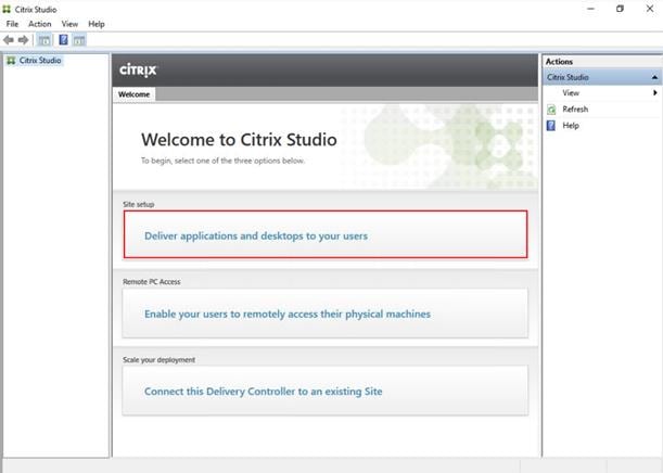
Step 2. Select the radio button for An empty, unconfigured Site.
Step 3. Enter a site name.
Step 4. Click Next.
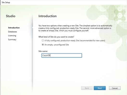
Step 5. Provide the Database Server Locations for each data type.
Note: For an SQL AlwaysOn Availability Group, use the group’s listener DNS name.
Step 6. Click Select to specify additional controllers (Optional at this time. Additional controllers can be added later).
Step 7. Click Next.
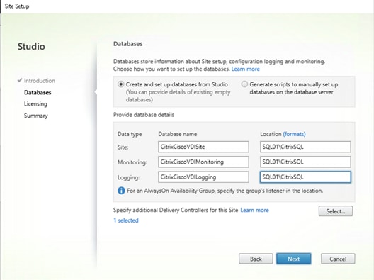
Step 8. Provide the FQDN of the license server.
Step 9. Click Connect to validate and retrieve any licenses from the server.
Note: If no licenses are available, you can use the 30-day free trial or activate a license file.
Step 10. Select the appropriate product edition using the license radio button.
Step 11. Click Next.
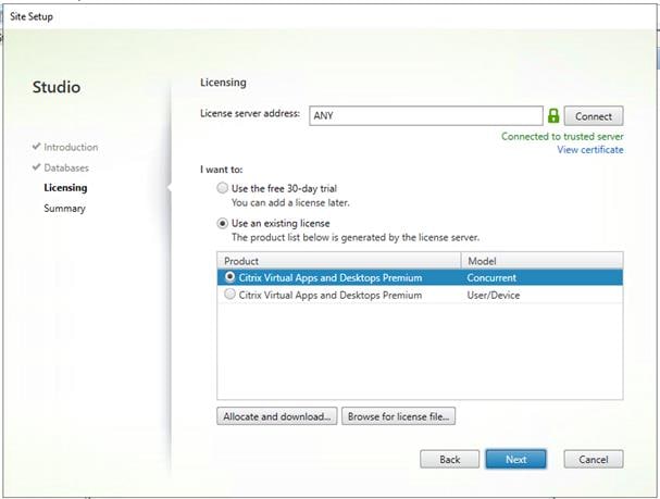
Step 12. Verify information on the Summary page.
Step 13. Click Finish.
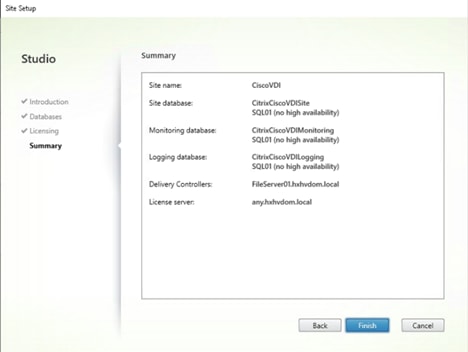
Procedure 6. Configure the Citrix Virtual Apps and Desktops Site Hosting Connection
Step 1. From Configuration > Hosting in Studio, click Add Connection and Resources.
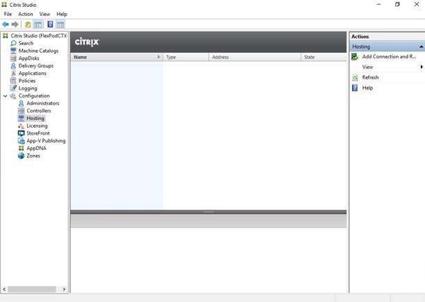
Step 2. On the Connection page:
a. Select the Connection type of VMware vSphere.
b. Enter the FQDN of the vCenter server (in Server_FQDN/sdk format).
c. Enter the username (in domain\username format) for the vSphere account.
d. Provide the password for the vSphere account.
e. Provide a connection name.
f. Select the tool to create virtual machines: Machine Creation Services or Citrix Provisioning.
Step 3. Click Next.
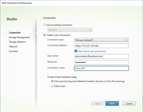
Step 4. Accept the certificate and click OK to trust the hypervisor connection.
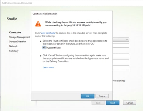
Step 5. Select a storage management method:
a. Select a cluster that will be used by this connection.
b. Check Use storage shared by hypervisors radio button.
Step 6. Click Next.
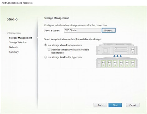
Step 7. Select the Storage to be used by this connection, use all provisioned for desktops datastores.
Step 8. Click Next.
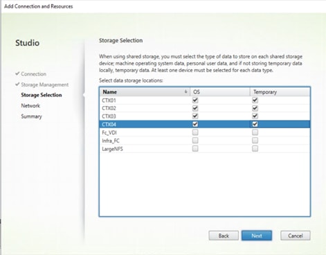
Step 9. Select the Network to be used by this connection.
Step 10. Click Next.
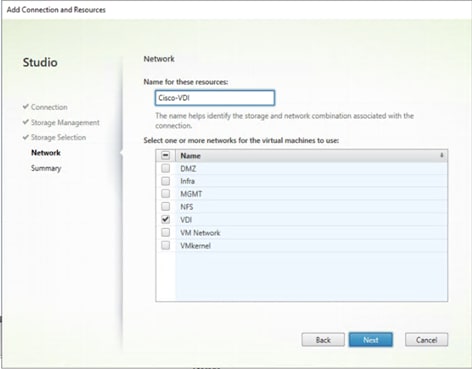
Step 11. Review Add Connection and Recourses Summary.
Step 12. Click Finish.
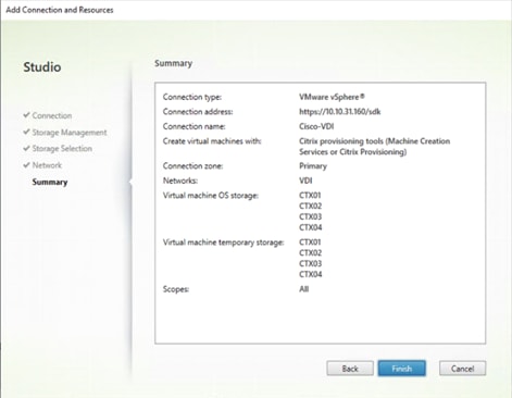
Procedure 7. Configure the Citrix Virtual Apps and Desktops Site Administrators
Step 1. Connect to the Citrix Virtual Apps and Desktops server and open Citrix Studio Management console.
Step 2. From the Configuration menu, right-click Administrator and select Create Administrator from the drop-down list.
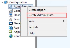
Step 3. Select or Create appropriate scope and click Next.
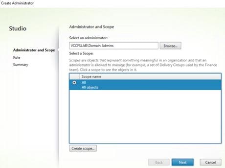
Step 4. Select an appropriate Role.
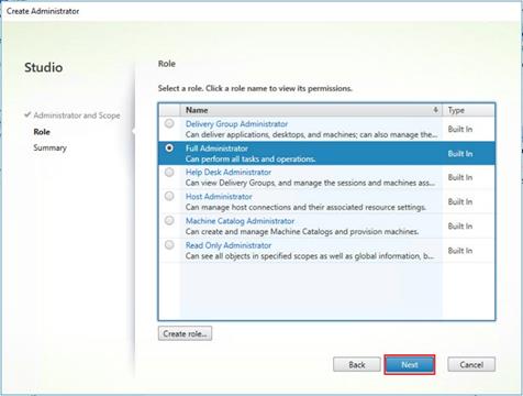
Step 5. Review the Summary, check Enable administrator and click Finish.
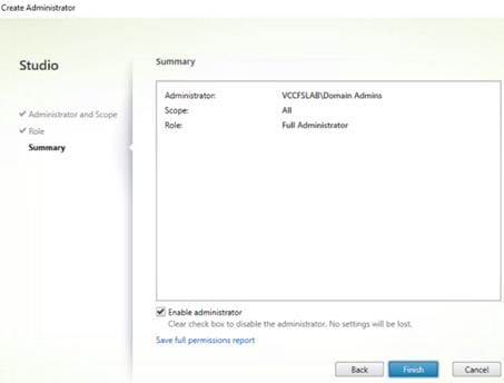
Procedure 8. Install and Configure StoreFront
Note: Citrix StoreFront stores aggregate desktops and applications from Citrix Virtual Apps and Desktops sites, making resources readily available. In this CVD, we created two StoreFront servers on dedicated virtual machines.
Step 1. To begin the installation of the StoreFront, connect to the first StoreFront server and launch the installer from the Citrix_Virtual_Apps_and_Desktops_7_2203 ISO.
Step 2. Click Start.

Step 3. Click Extend Deployment Citrix StoreFront.
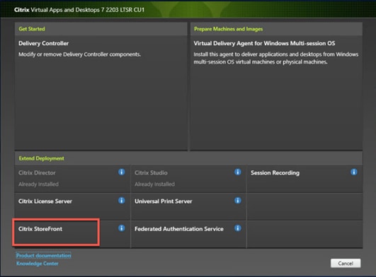
Step 4. Indicate your acceptance of the license by selecting I have read, understand, and accept the terms of the license agreement.
Step 5. Click Next.
Step 6. Review the prerequisites and click Next.
Step 7. Click Install.
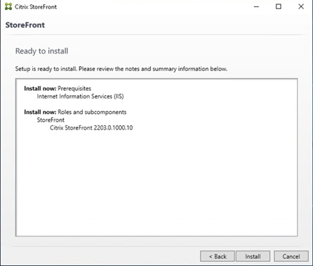
Step 8. Click Finish.
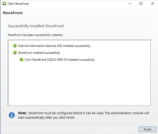
Step 9. Click Yes to reboot the server.
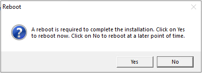
Step 10. Open the StoreFront Management Console.
Step 11. Click Create a new deployment.
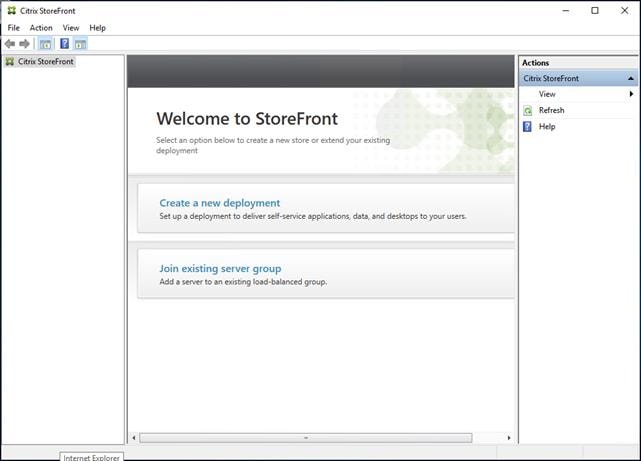
Step 12. Specify a name for your Base URL.
Step 13. Click Next.
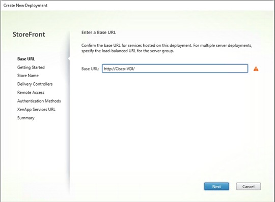
Note: For a multiple server deployment use the load balancing environment in the Base URL box.
Step 14. Click Next.
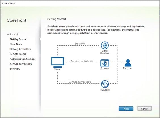
Step 15. Specify a name for your store and click Next.
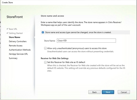
Step 16. Click Add to specify the Delivery controllers for your new Store.
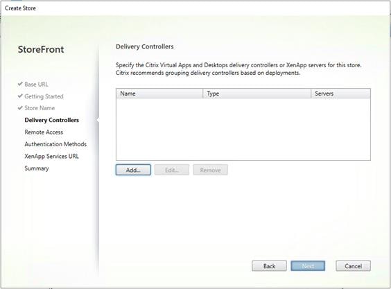
Step 17. Add the required Delivery Controllers to the store.
Step 18. Click OK.
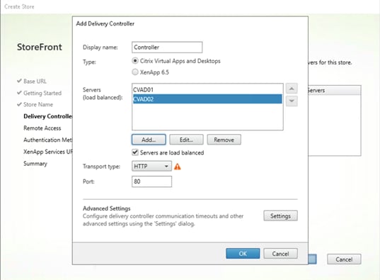
Step 19. Click Next.
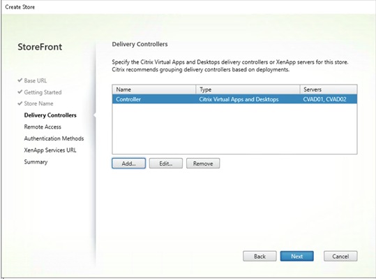
Step 20. Specify how connecting users can access the resources, in this environment only local users on the internal network are able to access the store.
Step 21. Click Next.
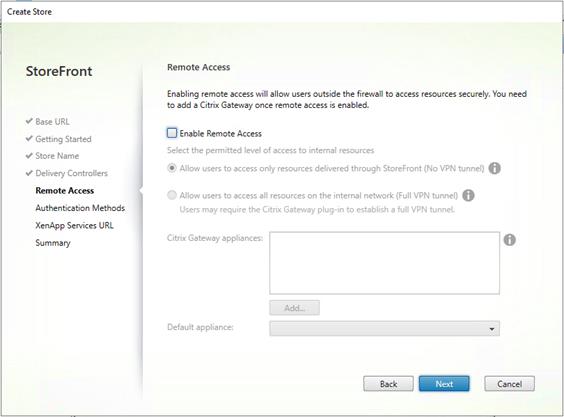
Step 22. On the ”Authentication Methods” page, select the methods your users will use to authenticate to the store. The following methods were configured in this deployment:
● Username and password: Users enter their credentials and are authenticated when they access their stores.
● Domain passthrough: Users authenticate to their domain-joined Windows computers and their credentials are used to log them in automatically when they access their stores.
Step 23. Click Next.
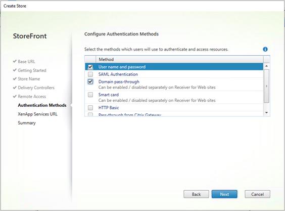
Step 24. Configure the XenApp Service URL for users who use PNAgent to access the applications and desktops.
Step 25. Click Create.
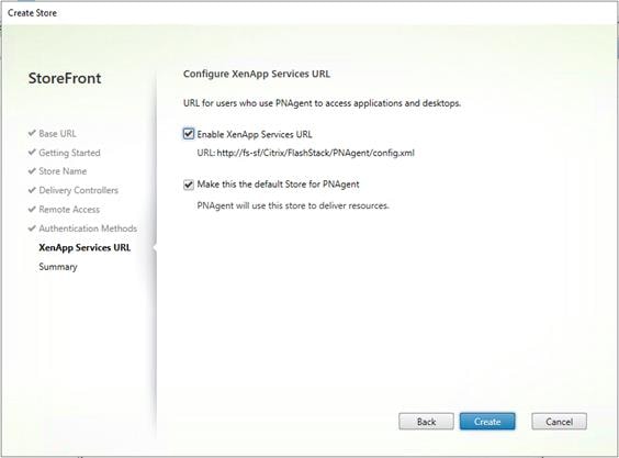
Step 26. After creating the store click Finish.
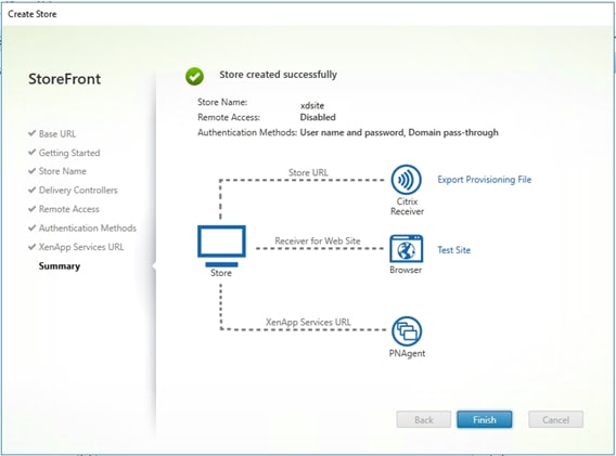
Procedure 9. Additional StoreFront Configuration
Note: After the first StoreFront server is completely configured and the Store is operational, you can add additional servers.
Step 1. Install the second StoreFront using the installation steps detailed in Procedure 8.
Step 2. Connect to the first StoreFront server.
Step 3. To add the second server and generate the authorization information that allows the additional StoreFront server to join the server group, select Add Server from Actions pane in the Server Group.
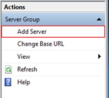
Step 4. Copy the authorization code.
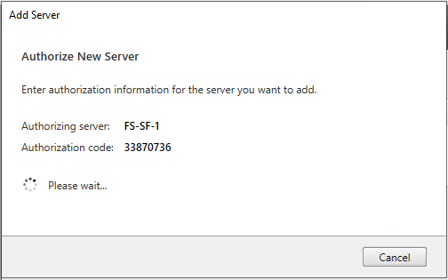
Step 5. From the StoreFront Console on the second server select Join existing server group.
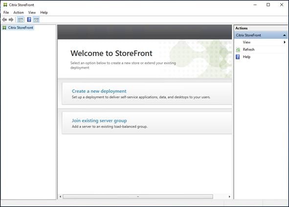
Step 6. In the Join Server Group dialog, enter the name of the first Storefront server and paste the Authorization code into the Join Server Group dialog.
Step 7. Click Join.
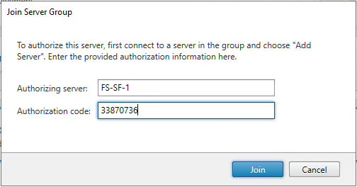
A message appears when the second server has joined successfully.
Step 8. Click OK.
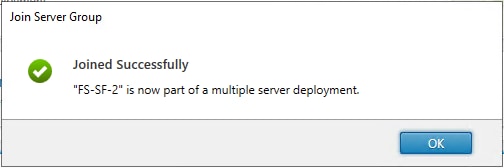
The second StoreFront is now in the Server Group.
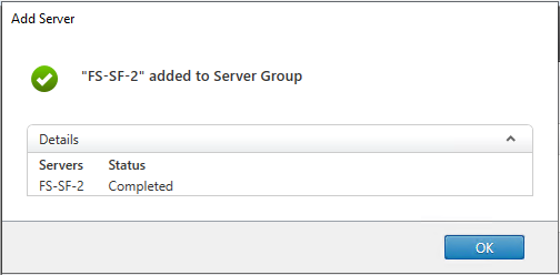
Install and Configure Citrix Provisioning Server 2203
In most implementations, there is a single vDisk providing the standard image for multiple target devices. Thousands of target devices can use a single vDisk shared across multiple Provisioning Services (PVS) servers in the same farm, simplifying virtual desktop management. This section describes the installation and configuration tasks required to create a PVS implementation.
The PVS server can have many stored vDisks, and each vDisk can be several gigabytes in size. Your streaming performance and manageability can be improved using a RAID array, SAN, or NAS. PVS software and hardware requirements are available in the Provisioning Services 2203 document.
Procedure 1. Configure Prerequisites
Step 1. Set the following Scope Options on the DHCP server hosting the PVS target machines:
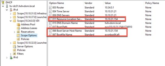
Step 2. Create a DNS host records with multiple PVS Servers IP for TFTP Load Balancing:
● As a Citrix best practice cited in this CTX article, apply the following registry setting both the PVS servers and target machines:
HKEY_LOCAL_MACHINE\SYSTEM\CurrentControlSet\Services\TCPIP\Parameters\
Key: "DisableTaskOffload" (dword)
Value: "1"
Note: Only one MS SQL database is associated with a farm. You can choose to install the Provisioning Services database software on an existing SQL database, if that machine can communicate with all Provisioning Servers within the farm, or with a new SQL Express database machine, created using the SQL Express software that is free from Microsoft.
The following databases are supported: Microsoft SQL Server 2008 SP3 through 2021 (x86, x64, and Express editions). Please review the Citrix documentation for further reference.
Note: Microsoft SQL 2019 was installed separately for this CVD.
Procedure 2. Install and Configure Citrix Provisioning Service 2203
Step 1. Connect to Citrix Provisioning server and launch Citrix Provisioning Services 2203 ISO and let AutoRun launch the installer.
Step 2. Click Console Installation.
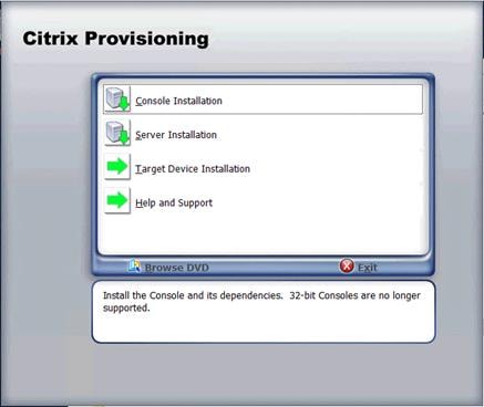
Step 3. Click Install to start the console installation.
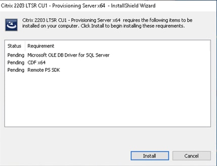
Step 4. Read the .NET License Agreement. If acceptable, check I have read and accept the license terms.
Step 5. Click Next.
Step 6. Click Finish.
Step 7. Restart the Virtual Machine.
Step 8. Logging into the Operating system automatically launches the installation wizard.
Step 9. Click Next.
Step 10. Read the Citrix License Agreement. If acceptable, select the radio button I accept the terms in the license agreement.
Step 11. Click Next.
Step 12. Optional; provide User Name and Organization.
Step 13. Click Next.
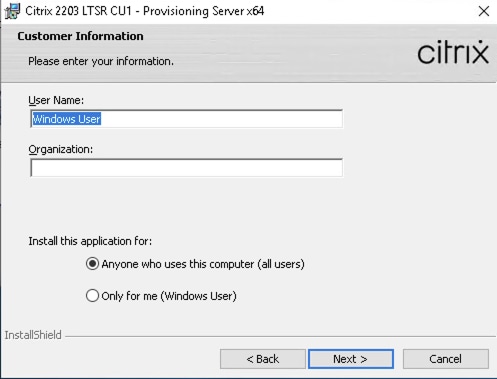
Step 14. Accept the default path.
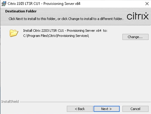
Step 15. Click Install.
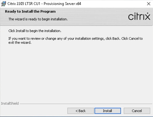
Step 16. Click Finish after successful installation.
Step 17. From the main installation screen, select Server Installation.
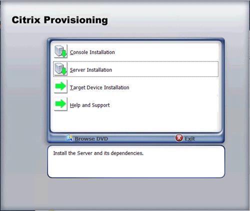
Step 18. Click Install on the prerequisites dialog.

Step 19. Click Next when the Installation wizard starts.
Step 20. Review the license agreement terms. If acceptable, select the radio button I accept the terms in the license agreement.
Step 21. Click Next.
Step 22. Select Automatically open all Citrix Provisioning ports. Click Next.
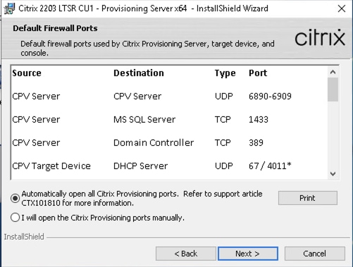
Step 23. Provide User Name and Organization information. Select who will see the application.
Step 24. Click Next.
Step 25. Accept the default installation location.
Step 26. Click Next.
Step 27. Click Install to begin the installation.
Step 28. Click Finish when the install is complete.
Procedure 3. Configure Citrix Provisioning Services
Step 1. Start the Citrix Provisioning Configuration wizard.
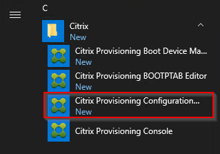
Step 2. Click Next.
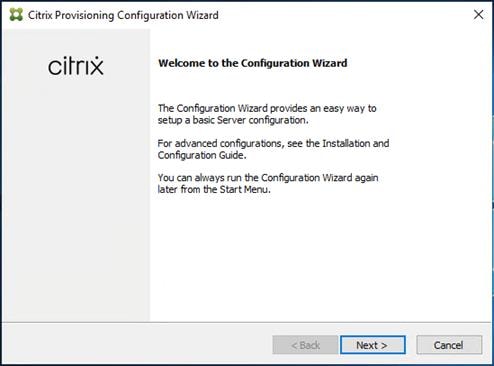
Step 3. Since the PVS server is not the DHCP server for the environment, select the radio button The service that runs on another computer.
Step 4. Click Next.
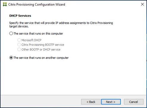
Step 5. Since DHCP boot options are used for TFTP services, select the radio button labeled The service that runs on another computer.
Step 6. Click Next.
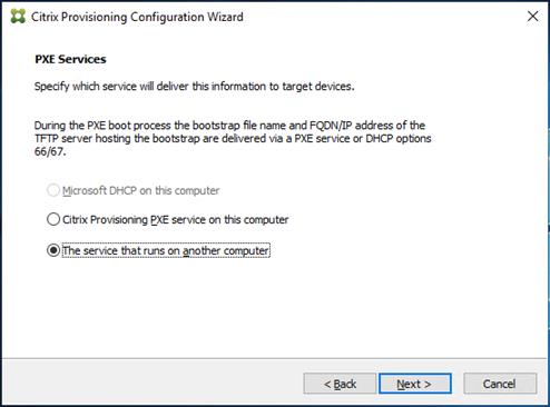
Step 7. Since this is the first server in the farm, select the radio button Create farm.
Step 8. Click Next.
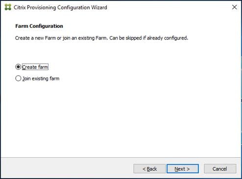
Step 9. Enter the FQDN of the SQL server.
Step 10. Click Next.

Step 11. Provide the Database, Farm, Site, and Collection name.
Step 12. Click Next.
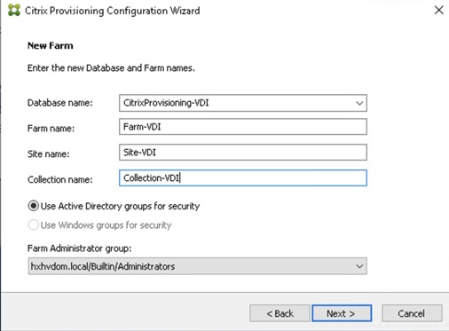
Step 13. Provide the vDisk Store details.
Step 14. Click Next.
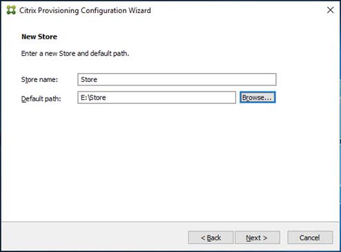
Step 15. For large scale PVS environment, it is recommended to create the share using support for CIFS/SMB3 on an enterprise ready File Server.
Step 16. Provide the FQDN of the license server.
Step 17. Optionally, provide a port number if changed on the license server.
Step 18. Click Next.
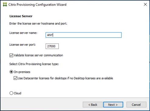
Step 19. If an Active Directory service account is not already setup for the PVS servers, create that account prior to clicking Next in this dialog.
Step 20. Select the Specified user account radio button.
Step 21. Complete the User name, Domain, Password, and Confirm password fields, using the PVS account information created earlier.
Step 22. Click Next.
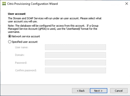
Step 23. Set the Days between password updates to 7.
Note: This will vary per environment. 7 days for the configuration was appropriate for testing purposes.
Step 24. Click Next.
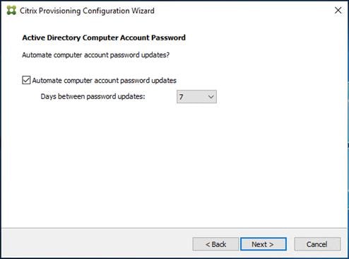
Step 25. Keep the defaults for the network cards.
Step 26. Click Next.
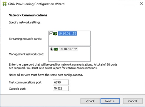
Step 27. Select Use the Citrix Provisioning Services TFTP service checkbox.
Step 28. Click Next.
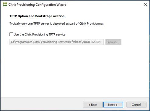
Step 29. If Soap Server is used, provide the details.
Step 30. Click Next.
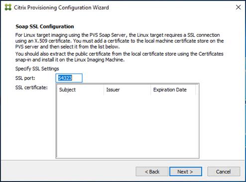
Step 31. If desired, fill in Problem Report Configuration.
Step 32. Click Next.
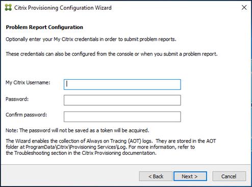
Step 33. Click Finish to start the installation.
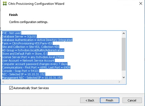
Step 34. When the installation is completed, click Done.

Procedure 4. Install Additional PVS Servers
Note: Complete the installation steps on the additional PVS servers up to the configuration step where it asks to Create or Join a farm. In this CVD, we repeated the procedure to add a total of three PVS servers.
This procedure details how to join additional Provisioning servers to the farm already configured in the previous steps.
Step 1. On the Farm Configuration dialog, select Join existing farm.
Step 2. Click Next.

Step 3. Provide the FQDN of the SQL Server.
Step 4. Click Next.
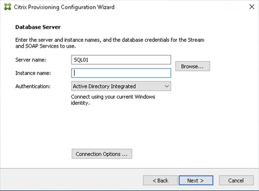
Step 5. Accept the Farm Name.
Step 6. Click Next.
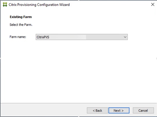
Step 7. Accept the Existing Site.
Step 8. Click Next.
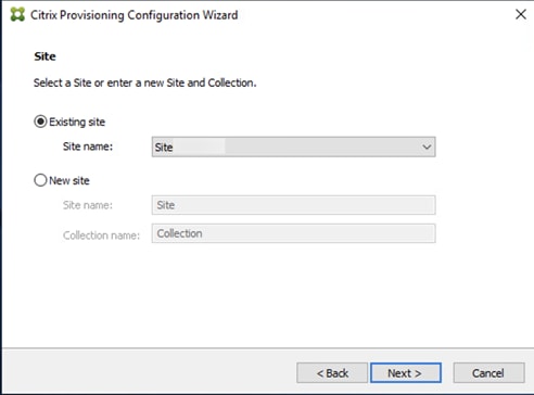
Step 9. Accept the existing vDisk store.
Step 10. Click Next.
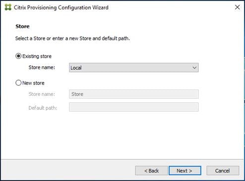
Step 11. Provide the FQDN of the license server.
Step 12. Optional; provide a port number if changed on the license server.
Step 13. Click Next.
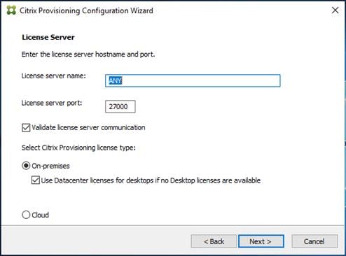
Step 14. Provide the PVS service account information.
Step 15. Click Next.
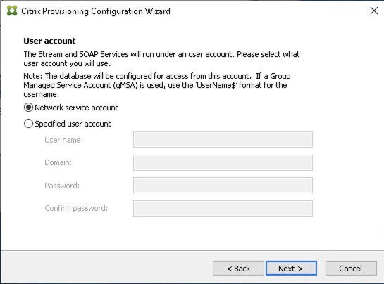
Step 16. Set the Days between password updates to 7.
Step 17. Click Next.
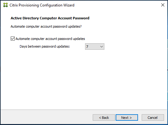
Step 18. Accept the network card settings.
Step 19. Click Next.
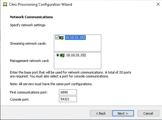
Step 20. Check the box for Use the Citrix Provisioning Services TFTP service.
Step 21. Click Next.
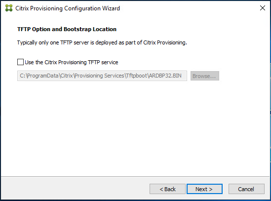
Step 22. If Soap Server is used, provide details.
Step 23. Click Next.
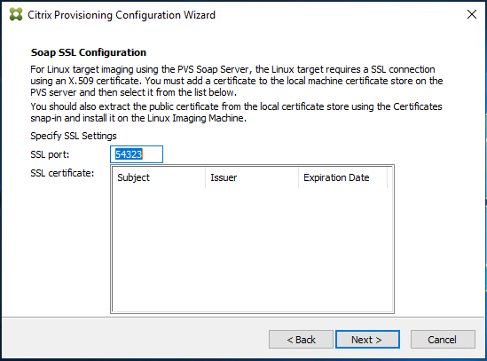
Step 24. If desired, fill in the Problem Report Configuration.
Step 25. Click Next.
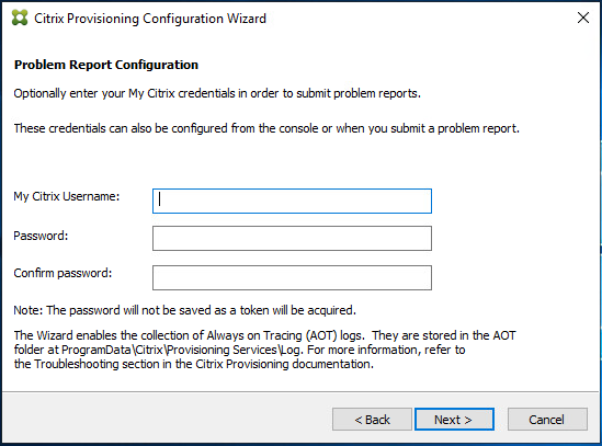
Step 26. Click Finish to start the installation process.

Step 27. Click Done when the installation finishes.
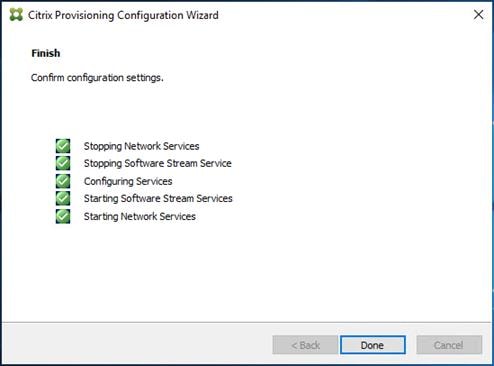
Note: Optionally, you can install the Provisioning Services console on the second PVS server following the procedure in the section Install the Citrix Provisioning Server Target Device Software.
Step 28. After completing the steps to install the three additional PVS servers, launch the Provisioning Services Console to verify that the PVS Servers and Stores are configured and that DHCP boot options are defined.
Step 29. Launch Provisioning Services Console and select Connect to Farm.
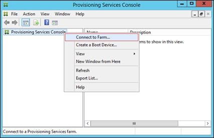
Step 30. Enter Localhost for the PVS1 server.
Step 31. Click Connect.
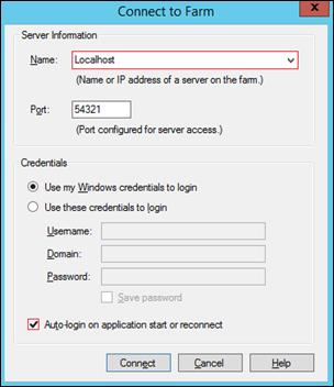
Step 32. Right-click Store and select Properties from the drop-down list.
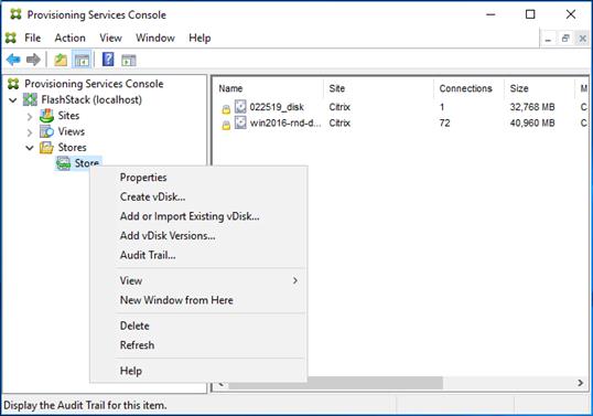
Step 33. In the Store Properties dialog, add the Default store path to the list of Default write cache paths.
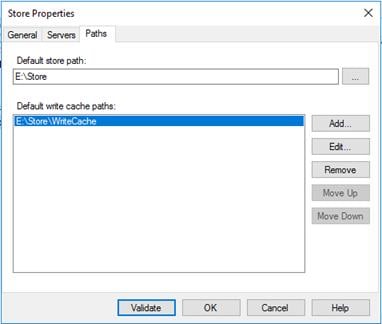
Step 34. Click Validate. If the validation is successful, click Close and then click OK to continue.
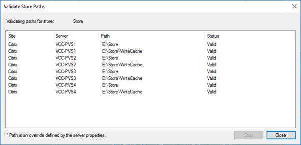
Procedure 5. Install Citrix Virtual Apps and Desktops Virtual Desktop Agents
Virtual Delivery Agents (VDAs) are installed on the server and workstation operating systems and enable connections for desktops and apps. The following procedure was used to install VDAs for both Single-session OS and Multi-session OS.
By default, when you install the Virtual Delivery Agent, Citrix User Profile Management is installed silently on master images. (Using profile management as a profile solution is optional, but FSLogix was used for this CVD and is described in a later section.)
Step 1. Launch the Citrix Virtual Apps and Desktops installer from the Citrix_Virtual_Apps_and_Desktops_7_2203 ISO.
Step 2. Click Start on the Welcome Screen.

Step 3. To install the VDA for the Hosted Virtual Desktops (VDI), select Virtual Delivery Agent for Windows Single-session OS.
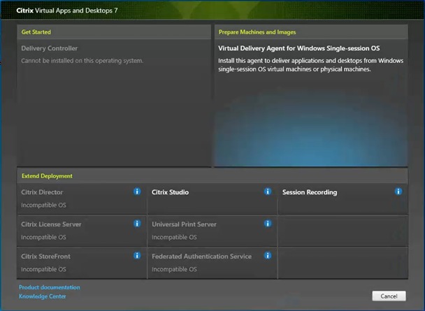
Step 4. Complete the steps found in the Virtual Delivery Agent installation.
Step 5. Select Create a master MCS image.
Step 6. Click Next.
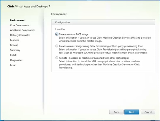
Step 7. Select Create a master image using Citrix Provisioning or third-party provisioning tools when building image to be delivered with Citrix Provisioning tools.
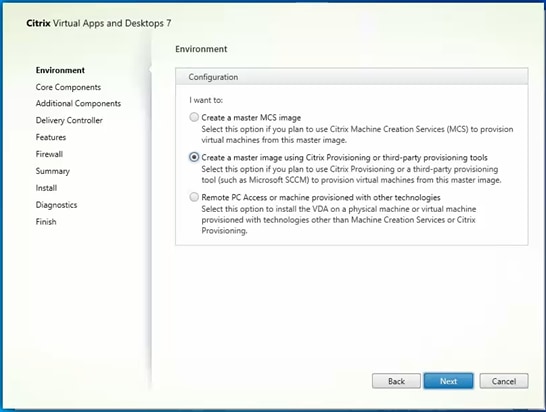
Step 8. Optional; do not select the Citrix Workspace App.
Step 9. Click Next.
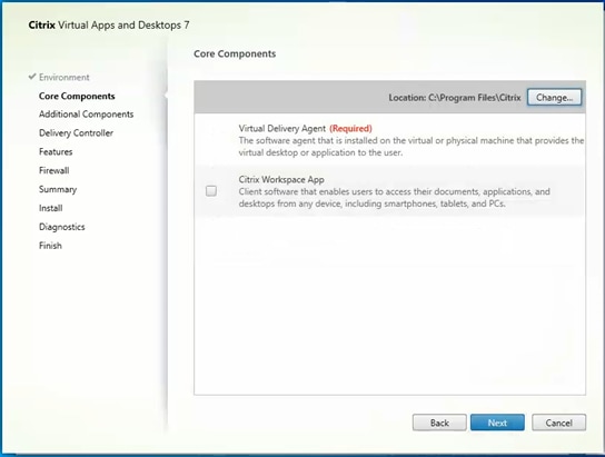
Step 10. Select the additional components required for your image.
Note: In this design, only the default components were installed on the image.
Step 11. Click Next.
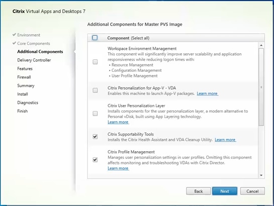
Step 12. Configure the Delivery Controllers.
Step 13. Click Next.
Step 14. Optional; select additional features.
Step 15. Click Next.
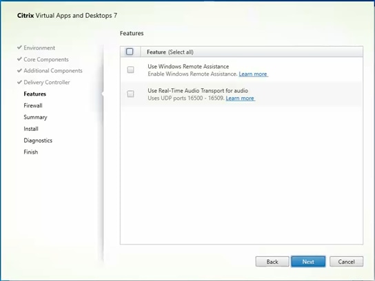
Step 16. For firewall rules, select Automatically.
Step 17. Click Next.
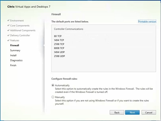
Step 18. Verify the Summary and click Install.
Step 19. Optional; configure Citrix Call Home participation.
Step 20. Click Next.
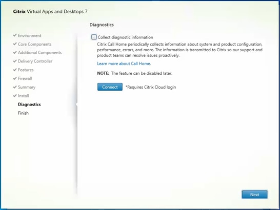
Step 21. Check Restart Machine.
Step 22. Click Finish and the machine will reboot automatically.
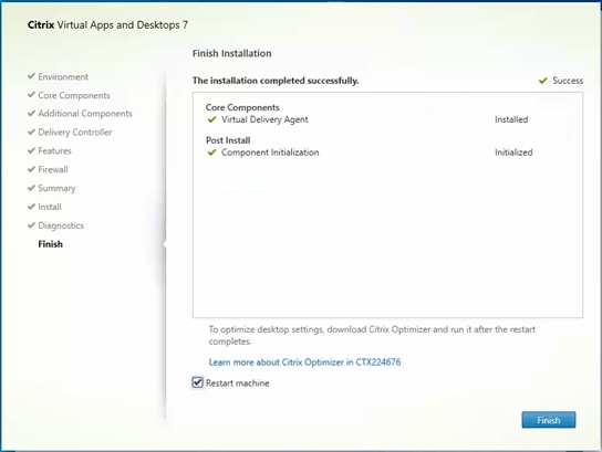
Install the Citrix Provisioning Server Target Device Software
The Master Target Device refers to the target device from which a hard disk image is built and stored on a vDisk. Provisioning Services then streams the contents of the vDisk created to other target devices. This procedure installs the PVS Target Device software that is used to build the RDS and VDI golden images.
Procedure 1. Install the Citrix Provisioning Server Target Device software
Step 1. Launch the PVS installer from the Citrix_Provisioning_2203 ISO.
Step 2. Click Target Device Installation.
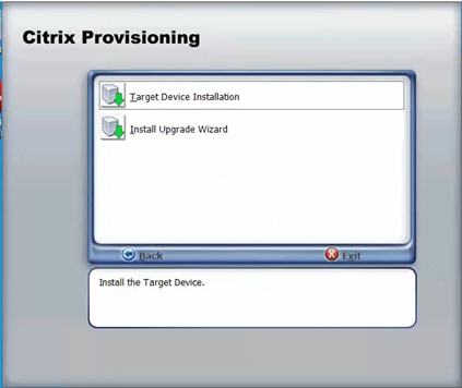
Note: The installation wizard will check to resolve dependencies and then begin the PVS target device installation process.
Step 3. Click Next.
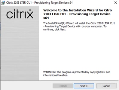
Step 4. Indicate your acceptance of the license by selecting I have read, understand, and accept the terms of the license agreement.
Step 5. Click Next.
Step 6. Optional; provide the Customer information.
Step 7. Click Next.
Step 8. Accept the default installation path.
Step 9. Click Next.
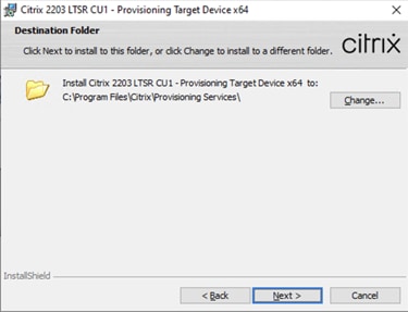
Step 10. Click Install.
Step 11. Deselect the checkbox to launch the Imaging Wizard and click Finish.
Step 12. Click Yes to reboot the machine.
Procedure 2. Create Citrix Provisioning Server vDisks
The PVS Imaging Wizard automatically creates a base vDisk image from the master target device.
The PVS Imaging Wizard's Welcome page appears.
Step 1. Click Next.
Step 2. The Connect to Farm page appears. Enter the name or IP address of a Provisioning Server within the farm to connect to and the port to use to make that connection.
Step 3. Use the Windows credentials (default) or enter different credentials.
Step 4. Click Next.
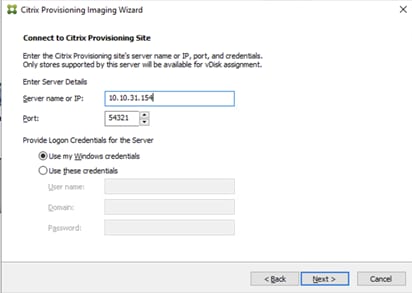
Step 5. Select Create a vDisk.
Step 6. Click Next.
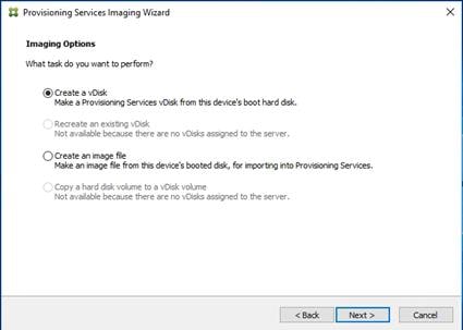
The Add Target Device page appears.
Step 7. Select the Target Device Name, the MAC address associated with one of the NICs that was selected when the target device software was installed on the master target device, and the Collection to which you are adding the device.
Step 8. Click Next.
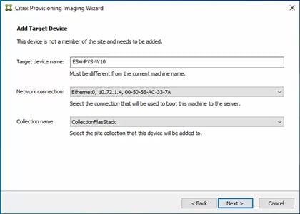
Step 9. The New vDisk dialog displays. Enter the vDisk name.
Step 10. Select the Store where the vDisk will reside. Select the vDisk type, either Fixed or Dynamic, from the drop-down list.
Note: This CVD used Dynamic rather than Fixed vDisks.
Step 11. Click Next.
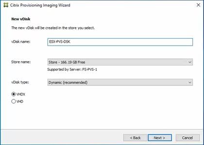
Step 12. On the Microsoft Volume Licensing page, select the volume license option to use for target devices. For this CVD, volume licensing is not used, so the None button is selected.
Step 13. Click Next.
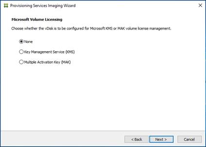
Step 14. Select Image entire boot disk on the Configure Image Volumes page.
Step 15. Click Next.
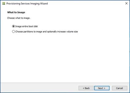
Step 16. Select Optimize for hard disk again for Provisioning Services before imaging on the Optimize Hard Disk for Provisioning Services.
Step 17. Click Next.
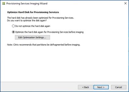
Step 18. Click Create on the Summary page.
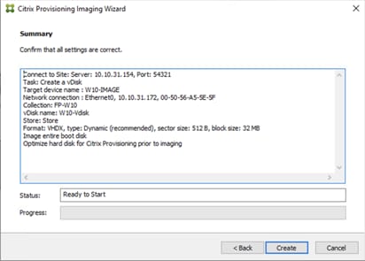
Step 19. Review the configuration and click Continue.
Step 20. When prompted, click No to shut down the machine.
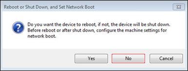
Step 21. Edit the VM options and under Boot Options, check the box for During the next boot, force entry into the EFI setup.
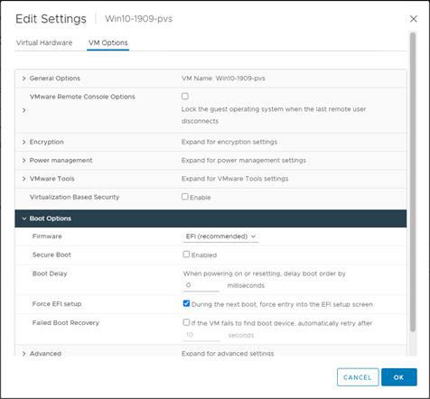
Step 22. Configure the VM settings for EFI network boot.
Step 23. Click Commit changes and exit.
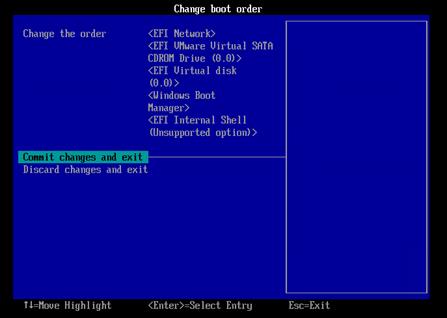
Step 24. After restarting the virtual machine, log into the master target. The PVS imaging process begins, copying the contents of the C: drive to the PVS vDisk located on the server.
Note: If prompted to Format disk, disregard the message, and allow Provisioning Imaging Wizard to finish.
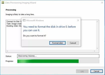
Step 25. A message is displayed when the conversion is complete, click Done.
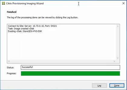
Step 26. Shutdown the virtual machine used as the VDI or RDS master target.
Step 27. Connect to the PVS server and validate that the vDisk image is available in the Store.
Step 28. Right-click the newly created vDisk and select Properties.
Step 29. On the vDisk Properties dialog, change Access mode to Standard Image (multi-device, read-only access).
Step 30. Set the Cache Type to Cache in device RAM with overflow on hard disk.
Step 31. Set Maximum RAM size (MBs): 256.
Step 32. Click OK.
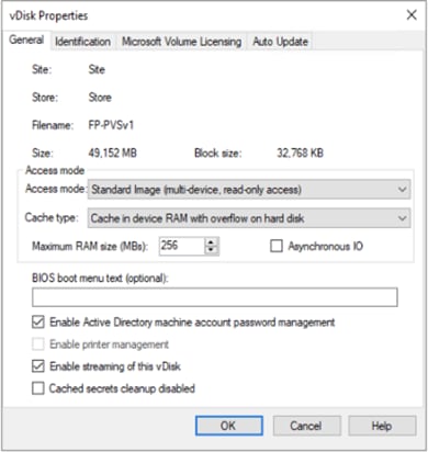
Provision Virtual Desktop Machines
Citrix Provisioning Services Citrix Virtual Desktop Setup Wizard
Procedure 1. Create PVS Streamed Virtual Desktop Machines
Step 1. Create a Master Target Virtual Machine.
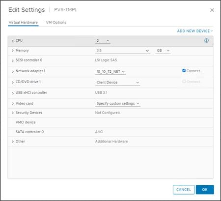
Step 2. Right-click and select Clone then select Clone to Template.
Step 3. Start the Citrix Virtual Apps and Desktops Setup Wizard from the Provisioning Services Console.
Step 4. Click Sites.
Step 5. Right-click the site.
Step 6. Select Citrix Virtual Desktop Setup Wizard… .
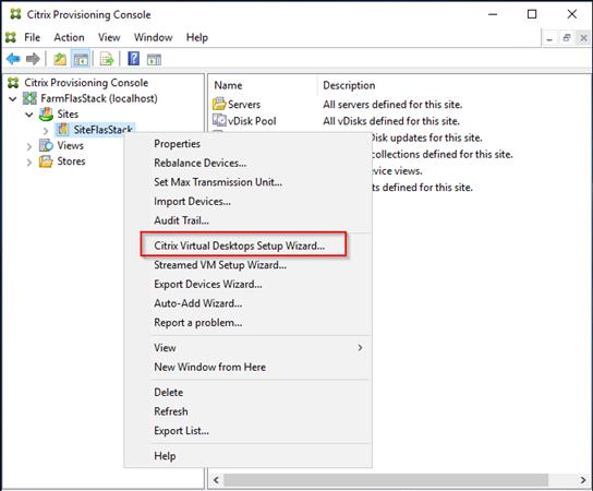
Step 7. Click Next.
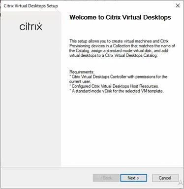
Step 8. Enter the address of the Citrix Virtual Desktop Controller that will be used for the wizard operations.
Step 9. Click Next.
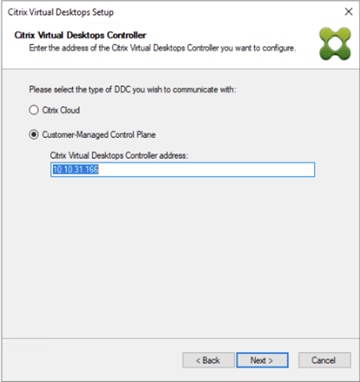
Step 10. Select the Host Resources that will be used for the wizard operations.
Step 11. Click Next.
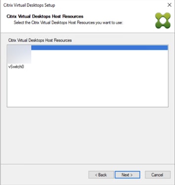
Step 12. Provide Citrix Virtual Desktop Controller credentials.
Step 13. Click OK.
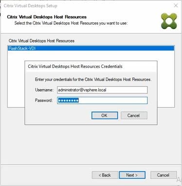
Step 14. Select the template previously created.
Step 15. Click Next.
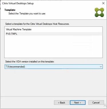
Step 16. Select the virtual disk (vDisk) that will be used to stream the provisioned virtual machines.
Step 17. Click Next.
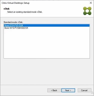
Step 18. Select Create new catalog.
Step 19. Provide a Catalog name.
Step 20. Click Next.
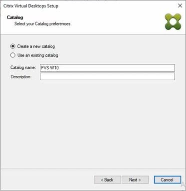
Step 21. Select Single-session OS for Machine catalog Operating System.
Step 22. Click Next.
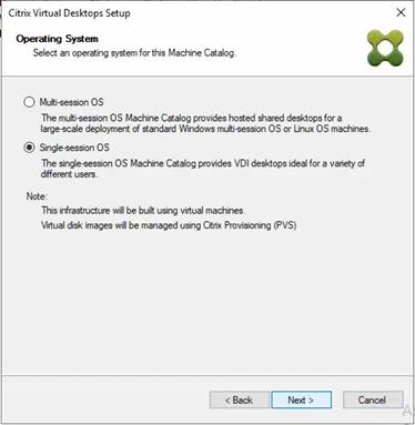
Step 23. Select A random, pooled virtual desktop each time.
Step 24. Click Next.
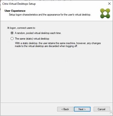
Step 25. On the Virtual machines dialog, specify the following:
● The number of virtual machines to create.
Note: It is recommended to create 200 or less per provisioning run. Create a single virtual machine at first to verify the procedure.
● 2 for Number of vCPUs for the virtual machine
● 3584 MB for the amount of memory for the virtual machine
● 6GB for the Local write cache disk.
Step 26. Click Next.
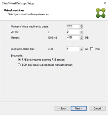
Step 27. Select the Create new accounts.
Step 28. Click Next.
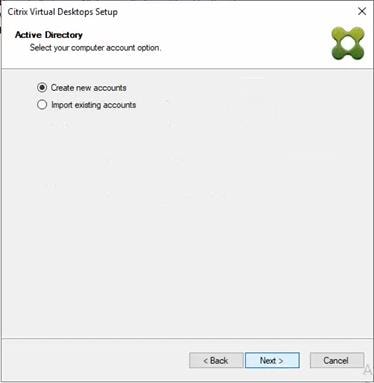
Step 29. Specify the Active Directory Accounts and Location. This is where the wizard should create computer accounts.
Step 30. Provide the Account naming scheme. An example name is shown in the text box below the naming scheme selection location.
Step 31. Click Next.
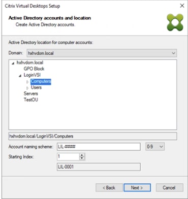
Step 32. Verify the information on the Summary screen.
Step 33. Click Finish to begin the virtual machine creation.
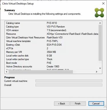
Step 34. When the wizard is done provisioning the virtual machines, click Done.
Step 35. When the wizard is done provisioning the virtual machines, verify the Machine Catalog on the Citrix Virtual Apps and Desktops Controller:
● Connect to a Citrix Virtual Apps and Desktops server and launch Citrix Studio.
● Select Machine Catalogs in the Studio navigation pane.
● Select a machine catalog.
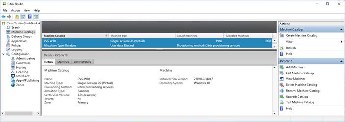
Procedure 2. Citrix Machine Creation Services
Step 1. Connect to a Citrix Virtual Apps and Desktops server and launch Citrix Studio.
Step 2. Select Create Machine Catalog from the Actions pane.
Step 3. Click Next.
Step 4. Select Single-session OS.
Step 5. Click Next.
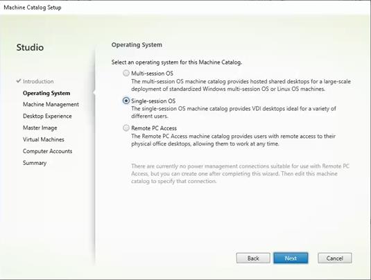
Step 6. Select Multi-session OS when using Windows Server 2022 desktops.
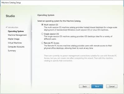
Step 7. Select the appropriate machine management.
Step 8. Click Next.
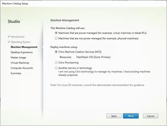
Step 9. For Desktop Experience, select I want users to connect to a new (random) desktop each time they log on.
Step 10. Click Next.
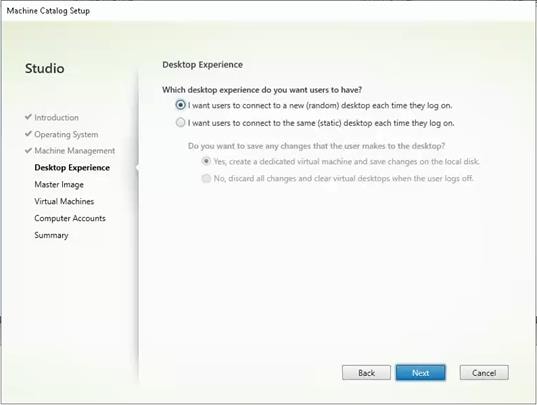
Step 11. Select a Virtual Machine to be used for Catalog Master Image.
Step 12. Click Next.
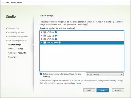
Step 13. Specify the number of desktops to create and machine configuration.
Step 14. Set amount of memory (MB) to be used by virtual desktops.
Step 15. Select Full Copy for machine copy mode.
Step 16. Click Next.
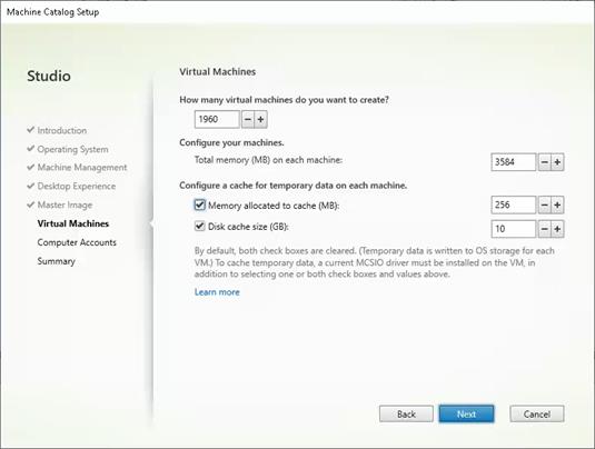
Step 17. Specify the AD account naming scheme and OU where accounts will be created.
Step 18. Click Next.
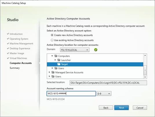
Step 19. On the Summary page specify Catalog name and click Finish to start the deployment.
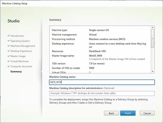
Procedure 3. Create Delivery Groups
Delivery Groups are collections of machines that control access to desktops and applications. With Delivery Groups, you can specify which users and groups can access which desktops and applications.
Note: The following steps describe the procedure to create a Delivery Group for persistent VDI desktops. When you have completed these steps, repeat the procedure to a Delivery Group for RDS desktops.
Step 1. Connect to a Citrix Virtual Apps and Desktops server and launch Citrix Studio.
Step 2. Right-click Deliver Group and select Create Delivery Group from the drop-down list.
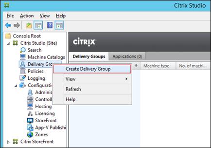
Step 3. Click Next.
Step 4. Specify the Machine Catalog and increment the number of machines to add.
Step 5. Click Next.
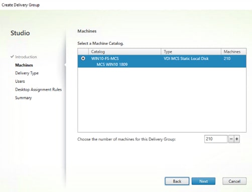
Step 6. Specify what the machines in the catalog will deliver: Desktops, Desktops and Applications, or Applications.
Step 7. Select Desktops.
Step 8. Click Next.
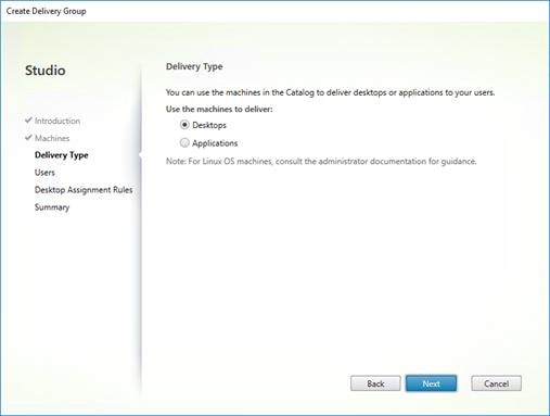
Step 9. To make the Delivery Group accessible, you must add users. Select Allow any authenticated users to use this Delivery Group.
Note: User assignment can be updated any time after Delivery group creation by accessing Delivery group properties in Desktop Studio.
Step 10. Click Next.
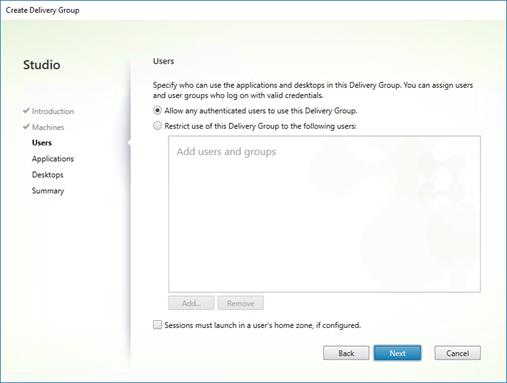
Step 11. Click Next.
Note: No applications are used in this design.
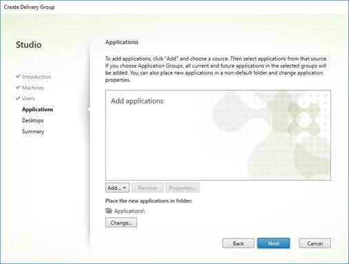
Step 12. Select Allow everyone with access to this Delivery Group to have a desktop assigned.
Step 13. Click Next.
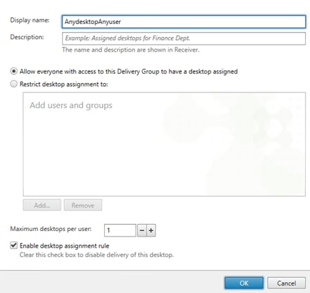
Step 14. On the Summary dialog, review the configuration. Enter a Delivery Group name and a Description (Optional).
Step 15. Click Finish.
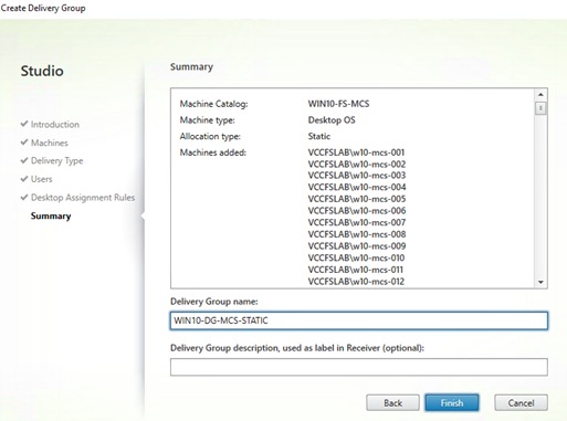
Citrix Studio lists the created Delivery Groups as well as the type, number of machines created, sessions, and applications for each group in the Delivery Groups tab.
Step 16. From the drop-down list, select Turn on Maintenance Mode.
Citrix Virtual Apps and Desktops Policies and Profile Management
Policies and profiles allow the Citrix Virtual Apps and Desktops environment to be easily and efficiently customized.
Configure Citrix Virtual Apps and Desktops Policies
Citrix Virtual Apps and Desktops policies control user access and session environments, and are the most efficient method of controlling connection, security, and bandwidth settings. You can create policies for specific groups of users, devices, or connection types with each policy. Policies can contain multiple settings and are typically defined through Citrix Studio.
Note: The Windows Group Policy Management Console can also be used if the network environment includes Microsoft Active Directory and permissions are set for managing Group Policy Objects).
Figure 38 shows the policies for Login VSI testing in this CVD.
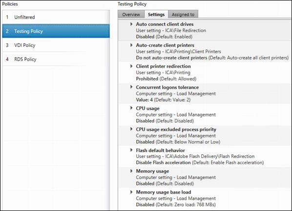
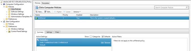
FSLogix for Citrix Virtual Apps and Desktops Profile Management
This section contains the following procedures:
● Configure FSLogix for Citrix Virtual Apps and Desktops Profiles Profile Container
● Configure FSLogix Profile Management
FSLogix for user profiles allows the Citrix Virtual Apps and Desktops environment to be easily and efficiently customized.
Procedure 1. Configure FSLogix for Citrix Virtual Apps and Desktops Profiles Profile Container
Profile Container is a full remote profile solution for non-persistent environments. Profile Container redirects the entire user profile to a remote location. Profile Container configuration defines how and where the profile is redirected.
Note: Profile Container is inclusive of the benefits found in Office Container.
Step 1. Verify that you meet all entitlement and configuration requirements.
Step 2. Download and install FSLogix Software
Step 3. Consider the storage and network requirements for your users' profiles (in this CVD, we used the Netapp A400 to store the FSLogix Profile disks).
Step 4. Verify that your users have storage permissions where profiles will be placed.
Step 5. Profile Container is installed and configured after stopping use of other solutions used to manage remote profiles.
Step 6. Exclude the VHD(X) files for Profile Containers from Anti-Virus (AV) scanning.
Procedure 2. Configure FSLogix Profile Management
Step 1. When the FSLogix software is downloaded, copy the fslogix.admx and fslogix.adml to the PolicyDefinitions folder in your domain to manage the settings with Group Policy.
Step 2. On your VDI master image, install the FSLogix agent FSLogixAppsSetup and accept all the defaults.
Step 3. Create a Group Policy object and link it to the Organizational Unit the VDI computer accounts.
Step 4. Right-click the FSLogix GPO policy.
Step 5. Enable FSLogix Profile Management.
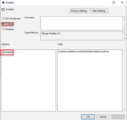
Step 6. Select Profile Type.
Note: In this solution, we used Read-Write profiles.
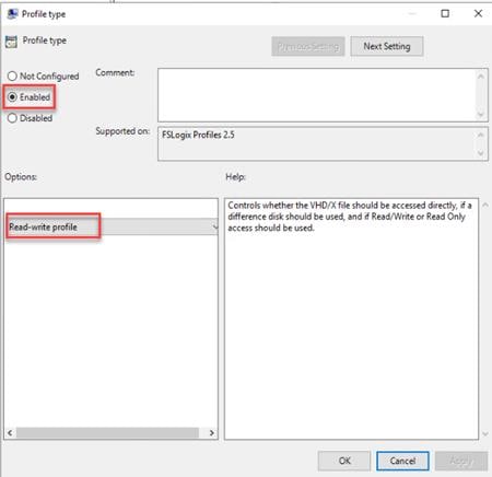
Step 7. Enter the location of the Profile location (our solution used a CIFS share on the NetApp Array).
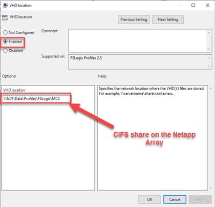
Note: We recommend using the Dynamic VHDX setting.
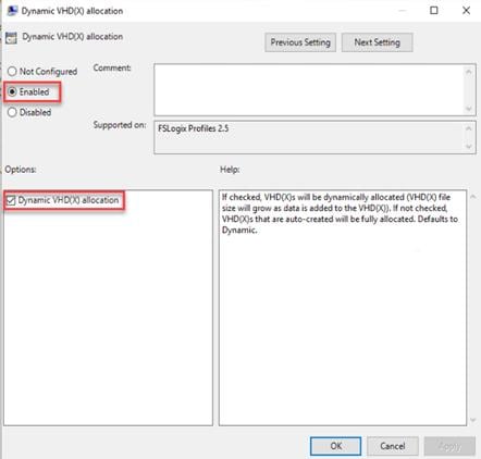
Note: VHDX is recommended over VHD.
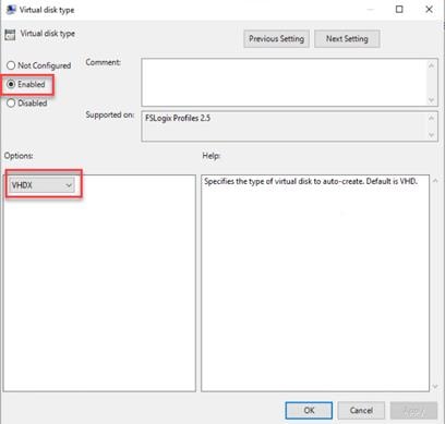
Note: We enabled the ‘Swap directory name components’ setting for an easier administration, but it is not necessary for improved performance.
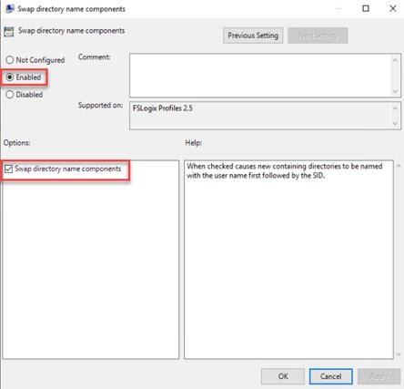
| Tech tip |
| FSLogix is an outstanding method of controlling the user experience and profile data in a VDI environment. There are many helpful settings and configurations for VDI with FSLogix that were not used in this solution. |
Hybrid Cloud Deployment for Disaster Recovery
This chapter contains the following:
● Deploy Cloud Volumes ONTAP in Microsoft Azure Cloud
● Set up SnapMirror relationship
Disasters can come in many forms for a business and protecting data with disaster recovery (DR) is a critical goal for businesses continuity. DR allows organizations to failover their business operations to a secondary location and later recover and failback to the primary site efficiently and reliably.
SnapMirror is disaster recovery technology, designed for failover from primary storage to secondary storage at a geographically remote site. As its name implies, SnapMirror creates a replica, or mirror, of your working data in secondary storage from which you can continue to serve data in the event of a catastrophe at the primary site.
Procedure 1. Access NetApp BlueXP
Step 1. To access NetApp BlueXP and other cloud services, you need to sign up here: NetApp Cloud Central.
Step 1. To deploy Connector in Microsoft Azure Cloud, go to: https://docs.netapp.com/us-en/cloud-manager-setup-admin/task-creating-connectors-azure.html#overview.
Procedure 3. Deploy Cloud Volumes ONTAP in Microsoft Azure Cloud
Step 1. To deploy CVO in Microsoft Azure Cloud, go to: https://docs.netapp.com/us-en/cloud-manager-cloud-volumes-ontap/task-getting-started-azure.html.
Procedure 4. Set up SnapMirror relationship
Step 1. In the BlueXP window, select your workspace and connector.
Step 2. Drag and drop the source on-prem ONTAP to the Azure Cloud Volumes ONTAP instance which will be your destination.
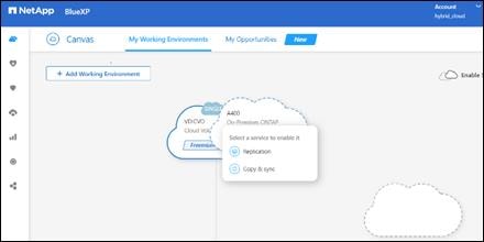
Step 3. In the Source Peering Setup select the intercluster LIF.
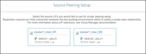
Step 4. In Source Volume Selection select the volume to replicate.
Step 5. In Destination Disk Type and Tiering select the default Destination Disk Type.
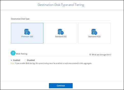
Step 6. In Destination Volume Name, accept all the defaults.
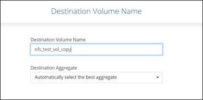
Step 7. Click Continue.
Step 8. Accept the default for the Max Transfer Rate.
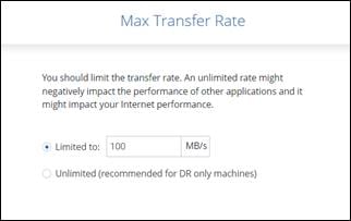
Step 9. Click Continue.
Step 10. Click Mirror to select a Replication Policy.
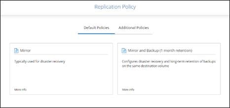
Note: To control the frequency of the replication updates, you can select a replication schedule. If you scroll down the window, you will see there are many from which to choose.
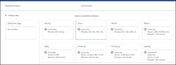
Step 11. Review and accept the choices by clicking the checkbox next to I understand ....
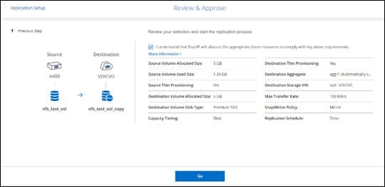
Step 12. Click Go.
Step 13. Click Timeline to monitor when the creation of the protection relationship is complete.
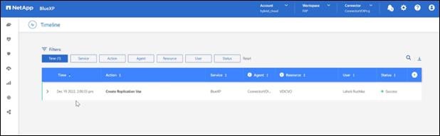
Step 14. Click the CVO instance and go to replication tab. Wait for the Mirror State to change to snapmirrored.
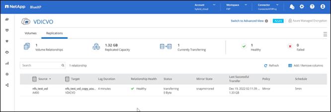
This chapter contains the following:
● Cisco UCS Test Configuration for Single Compute Node Scalability
● Testing Methodology and Success Criteria
● Single-Server Recommended Maximum Workload
Note: In this solution, we tested a single Cisco UCS X210c M7Compute Node Server to validate against the performance of one Compute Node and eleven Cisco UCS X210c M7Compute Node Servers across two chassis to illustrate linear scalability for each workload use case studied.
Cisco UCS Test Configuration for Single Compute Node Scalability
This test case validates Recommended Maximum Workload per host server using Citrix Virtual Apps and Desktops 7 LTSR with 420 RDS sessions, 325 VDI Non-Persistent sessions, and 325 VDI Persistent sessions.


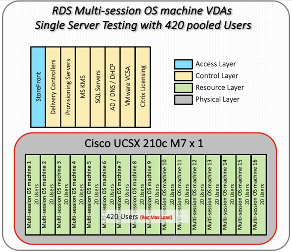
Hardware components:
● 2 Cisco UCS 6536 5th Generation Fabric Interconnects
● 1 (RDS/VDI Host) Cisco UCSX 210c-M7 Compute Nodes with INTEL 24-core processors, 2TB 4800MHz RAM for all host Compute Nodes
● Cisco UCS VIC 15231 CNA (1 per Compute Node)
● 2 Cisco Nexus N9K-C93180YC-FX3S Access Switches
● NetApp AFF A400
Software components:
● Cisco UCS firmware 5.2(0.230041)
● NetApp ONTAP 9.13. 1P3
● VMware ESXi 8.0 U1 for host Compute Nodes
● Citrix Virtual Apps and Desktops 7 LTSR VDI Desktops and RDS Desktops
● FSLogix
● Microsoft SQL Server 2022
● Microsoft Windows 11 64 bit, 2vCPU, 4 GB RAM, 40 GB HDD (master)
● Microsoft Windows Server 2022, 8vCPU, 32GB RAM, 60 GB vDisk (master)
● Microsoft Office 2021
● Login VSI 4.1.40 Knowledge Worker Workload (Benchmark Mode)
● NetApp Harvest, Graphite, and Grafana
Cisco UCS Configuration for Full Scale Testing
This test case validates thirty Compute Node workloads using RDS/Citrix Virtual Apps and Desktops 7 LTSR with 2500 RDS sessions, 2000 VDI Non-Persistent sessions, and 2000 VDI Persistent sessions. Server N+1 fault tolerance is factored into this solution for each workload and infrastructure cluster.

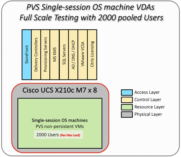

Hardware components:
● 2 Cisco UCS 6536 5th Generation Fabric Interconnects
● 4 (Infrastructure Hosts) Cisco UCS C220 M5 Rack Servers
● 8 (RDS/VDI Host) Cisco UCS C245-M7 Compute Nodes with INTEL 2.4GHz 32-core processors, 2TB 4800MHz RAM for all host Compute Nodes
● Cisco UCS VIC 15231 CNA (1 per Compute Node)
● 2 Cisco Nexus N9K-C93180YC-FX3S Access Switches
● 1 NetApp AFF A400 storage system (2x storage controllers- Active/Active High Availability pair) with 2x DS224C disk shelves, 24x 3.8TB SSD- 65TB usable / 130TB effective (2:1 efficiency)
Software components:
● Cisco UCS firmware 5.2(0.230041)
● VMware ESXi 8.0 U1 for host Compute Nodes
● Citrix RDS/Citrix Virtual Apps and Desktops 7 LTSR VDI Hosted Virtual Desktops and RDS Hosted Shared Desktops
● Citrix Provisioning Server 7 LTSR
● FSLogix for Profile Management
● Microsoft SQL Server 2022
● Microsoft Windows 11 64 bit, 2vCPU, 4 GB RAM, 32 GB vDisk (master)
● Microsoft Windows Server 2022, 8vCPU, 32GB RAM, 40 GB vDisk (master)
● Microsoft Office 2021
● Login VSI 4.1.40 Knowledge Worker Workload (Benchmark Mode)
● NAbox 3.3
Testing Methodology and Success Criteria
All validation testing was conducted on-site within the Cisco labs in San Jose, California.
The testing results focused on the entire process of the virtual desktop lifecycle by capturing metrics during the desktop boot-up, user logon and virtual desktop acquisition (also referred to as ramp-up,) user workload execution (also referred to as steady state), and user logoff for the Citrix RDS and Citrix Virtual Apps and Desktops Hosted Virtual Desktop and RDS Hosted Shared models under test.
Test metrics were gathered from the hypervisor, virtual desktop, storage, and load generation software to assess the overall success of an individual test cycle. Each test cycle was not considered passing unless all of the planned test users completed the ramp-up and steady state phases (described below) and unless all metrics were within the permissible thresholds as noted as success criteria.
Three successfully completed test cycles were conducted for each hardware configuration and results were found to be relatively consistent from one test to the next.
You can obtain additional information and a free test license from http://www.loginvsi.com.
This section contains the following procedure:
The following protocol was used for each test cycle in this study to ensure consistent results.
Pre-Test Setup for Single and Multi-Compute Node Testing
All virtual machines were shut down utilizing the Citrix Virtual Apps and Desktops Administrator and vCenter.
All Launchers for the test were shut down. They were then restarted in groups of 10 each minute until the required number of launchers was running with the Login VSI Agent at a “waiting for test to start” state.
All VMware ESXi VDI host Compute Nodes to be tested were restarted prior to each test cycle.
Procedure 1. Test Run Protocol
To simulate severe, real-world environments, Cisco requires the log-on and start-work sequence, known as Ramp Up, to complete in 48 minutes. Additionally, it’s required to start all sessions, whether single server users or full scale test users to become active within two minutes after the last session is launched.
In addition, Cisco requires that the Login VSI Benchmark method be used for all single server and scale testing. This assures that our tests represent real-world scenarios. For each of the three consecutive runs on single server tests, the same process was followed.
1. Time 0:00:00 Start Esxtop Logging on the following systems:
a. Infrastructure and VDI Host Compute Nodes used in the test run
b. vCenter used in the test run
c. All Infrastructure VMs used in test run (AD, SQL, brokers, image mgmt., and so on)
2. Time 0:00:10 Start Storage Partner Performance Logging on Storage System
3. Time 0:05: Boot Virtual Desktops/RDS Virtual Machines using Citrix Virtual Apps and Desktops Studio
Note: The boot rate should be around 10-12 VMs per minute per server.
4. Time 0:06 First machines boot
5. Time 0:30 Single Server or Scale target number of desktop VMs booted on 1 or more Compute Nodes
Note: No more than 30 minutes for boot up of all virtual desktops is allowed.
6. Time 0:35 Single Server or Scale target number of desktop VMs desktops registered on Citrix Virtual Apps and Desktops Studio
7. Virtual machine settling time.
Note: No more than 60 Minutes of rest time is allowed after the last desktop is registered on the Citrix Virtual Apps and Desktops Studio . Typically, a 30-40 minute rest period is sufficient.
8. Time 1:35 Start Login VSI 4.1.40 Office Worker Benchmark Mode Test, setting auto-logoff time at 900 seconds, with Single Server or Scale target number of desktop VMs utilizing sufficient number of Launchers (at 20-25 sessions/Launcher)
9. Time 2:23 Single Server or Scale target number of desktop VMs desktops launched (48 minute benchmark launch rate)
10. Time 2:25 All launched sessions must become active
Note: All sessions launched must become active for a valid test run within this window.
11. Time 2:40 Login VSI Test Ends (based on Auto Logoff 900 Second period designated above.)
12. Time 2:55 All active sessions logged off
13. Time 2:57 All logging terminated; Test complete
14. Time 3:15 Copy all log files off to archive; Set virtual desktops to maintenance mode through broker; Shutdown all Windows machines
15. Time 3:30 Reboot all hypervisor hosts.
16. Time 3:45 Ready for the new test sequence.
Our pass criteria for this testing follows:
● Cisco will run tests at a session count level that effectively utilizes the Compute Node capacity measured by CPU utilization, memory utilization, storage utilization, and network utilization. We will use Login VSI to launch version 4.1 Office Worker workloads. The number of launched sessions must equal active sessions within two minutes of the last session launched in a test as observed on the VSI Management console.
● The Citrix Virtual Apps and Desktops Studio should be monitored throughout the steady state to make sure of the following:
◦ All running sessions report In Use throughout the steady state
◦ No sessions move to unregistered, unavailable, or available state at any time during steady state
Within 20 minutes of the end of the test, all sessions on all launchers must have logged out automatically and the Login VSI Agent must have shut down. Stuck sessions define a test failure condition.
● Cisco requires three consecutive runs with results within +/-1% variability to pass the Cisco Validated Design performance criteria. For white papers written by partners, two consecutive runs within +/-1% variability are accepted. (All test data from partner run testing must be supplied along with the proposed white paper.)
● We will publish Cisco Validated Designs with our recommended workload following the process above and will note that we did not reach a VSImax dynamic in our testing. FlexPod Data Center with Cisco UCS and Citrix RDS/Citrix Virtual Apps and Desktops 7 LTSR on VMware ESXi 8.0 U12 Update 1 Test Results
The purpose of this testing is to provide the data needed to validate Citrix RDS Hosted Shared Desktop (RDS) and Citrix Virtual Apps and Desktops Hosted Virtual Desktop (VDI) randomly assigned, non-persistent with Citrix Provisioning Services 7 LTSR and Citrix Virtual Apps and Desktops Hosted Virtual Desktop (VDI) statically assigned, persistent full-clones models using ESXi and vCenter to virtualize Microsoft Windows 11 desktops and Microsoft Windows Server 2022 sessions on X-Series Compute Nodes M7 Compute Node Servers using a NetApp AFF250 storage system.
The information contained in this section provides data points that you may reference in designing you own implementations. These validation results are an example of what is possible under the specific environment conditions outlined here, and do not represent the full characterization of Citrix products with VMware vSphere.
Four test sequences, each containing three consecutive test runs generating the same result, were performed to establish single Compute Node performance and multi-Compute Node, linear scalability.
The philosophy behind Login VSI is different from conventional benchmarks. In general, most system benchmarks are steady state benchmarks. These benchmarks execute one or multiple processes, and the measured execution time is the outcome of the test. Simply put: the faster the execution time or the bigger the throughput, the faster the system is according to the benchmark.
Login VSI is different in approach. Login VSI is not primarily designed to be a steady state benchmark (however, if needed, Login VSI can act like one). Login VSI was designed to perform benchmarks for SBC or VDI workloads through system saturation. Login VSI loads the system with simulated user workloads using well known desktop applications like Microsoft Office, Internet Explorer, and Adobe PDF reader. By gradually increasing the amount of simulated users, the system will eventually be saturated. Once the system is saturated, the response time of the applications will increase significantly. This latency in application response times show a clear indication whether the system is (close to being) overloaded. As a result, by nearly overloading a system it is possible to find out what is its true maximum user capacity.
After a test is performed, the response times can be analyzed to calculate the maximum active session/desktop capacity. Within Login VSI this is calculated as VSImax. When the system is coming closer to its saturation point, response times will rise. When reviewing the average response time, it will be clear the response times escalate at saturation point.
This VSImax is the “Virtual Session Index (VSI).” With Virtual Desktop Infrastructure (VDI) and Terminal Services (RDS) workloads this is valid and useful information. This index simplifies comparisons and makes it possible to understand the true impact of configuration changes on hypervisor host or guest level.
Server-Side Response Time Measurements
It is important to understand why specific Login VSI design choices have been made. An important design choice is to execute the workload directly on the target system within the session instead of using remote sessions. The scripts simulating the workloads are performed by an engine that executes workload scripts on every target system and are initiated at logon within the simulated user’s desktop session context.
An alternative to the Login VSI method would be to generate user actions client side through the remoting protocol. These methods are always specific to a product and vendor dependent. More importantly, some protocols simply do not have a method to script user actions client side.
For Login VSI the choice has been made to execute the scripts completely server side. This is the only practical and platform independent solution, for a benchmark like Login VSI.
Calculate VSImax v4.1.x
The simulated desktop workload is scripted in a 48 minute loop when a simulated Login VSI user is logged on, performing generic Office worker activities. After the loop is finished it will restart automatically. Within each loop, the response times of sixteen specific operations are measured in a regular interval: sixteen times in within each loop. The response times of these five operations are used to determine VSImax.
The five operations from which the response times are measured are:
● Notepad File Open (NFO)
Loading and initiating VSINotepad.exe and opening the openfile dialog. This operation is handled by the OS and by the VSINotepad.exe itself through execution. This operation seems almost instant from an end-user’s point of view.
● Notepad Start Load (NSLD)
Loading and initiating VSINotepad.exe and opening a file. This operation is also handled by the OS and by the VSINotepad.exe itself through execution. This operation seems almost instant from an end-user’s point of view.
● Zip High Compression (ZHC)
This action copy's a random file and compresses it (with 7zip) with high compression enabled. The compression will very briefly spike CPU and disk IO.
● Zip Low Compression (ZLC)
This action copy's a random file and compresses it (with 7zip) with low compression enabled. The compression will very briefly disk IO and creates some load on the CPU.
● CPU
Calculates a large array of random data and spikes the CPU for a short period of time.
These measured operations within Login VSI do hit considerably different subsystems such as CPU (user and kernel), Memory, Disk, the OS in general, the application itself, print, GDI, and so on. These operations are specifically short by nature. When such operations become consistently long: the system is saturated because of excessive queuing on any kind of resource. As a result, the average response times will then escalate. This effect is clearly visible to end-users. If such operations consistently consume multiple seconds, the user will regard the system as slow and unresponsive.


When the test is finished, VSImax can be calculated. When the system is not saturated, and it could complete the full test without exceeding the average response time latency threshold, VSImax is not reached, and the amount of sessions ran successfully.
The response times are very different per measurement type, for instance Zip with compression can be around 2800 ms, while the Zip action without compression can only take 75ms. These response time of these actions are weighted before they are added to the total. This ensures that each activity has an equal impact on the total response time.
In comparison to previous VSImax models, this weighting much better represents system performance. All actions have very similar weight in the VSImax total. The following weighting of the response times is applied.
The following actions are part of the VSImax v4.1 calculation and are weighted as follows (US notation):
● Notepad File Open (NFO): 0.75
● Notepad Start Load (NSLD): 0.2
● Zip High Compression (ZHC): 0.125
● Zip Low Compression (ZLC): 0.2
● CPU: 0.75
This weighting is applied on the baseline and normal Login VSI response times.
With the introduction of Login VSI 4.1, we also created a new method to calculate the basephase of an environment. With the new workloads (Taskworker, Powerworker, and so on) enabling 'basephase' for a more reliable baseline has become obsolete. The calculation is explained below. In total 15 lowest VSI response time samples are taken from the entire test; the lowest 2 samples are removed, and the 13 remaining samples are averaged. The result is the Baseline.
Calculate the Basephase
1. Take the lowest 15 samples of the complete test.
2. From those 15 samples remove the lowest 2.
3. Average the 13 results that are left is the baseline.
The VSImax average response time in Login VSI 4.1.x is calculated on the amount of active users that are logged on the system.
Always a 5 Login VSI response time samples are averaged + 40 percent of the number of “active” sessions. For example, if the active sessions is 60, then latest 5 + 24 (=40 percent of 60) = 31 response time measurement are used for the average calculation.
To remove noise (accidental spikes) from the calculation, the top 5 percent, and bottom 5 percent of the VSI response time samples are removed from the average calculation, with a minimum of 1 top and 1 bottom sample. As a result, with 60 active users, the last 31 VSI response time sample are taken. From those 31 samples the top 2 samples are removed and lowest 2 results are removed (5 percent of 31 = 1.55, rounded to 2). At 60 users the average is then calculated over the 27 remaining results.
VSImax v4.1.x is reached when the VSIbase + a 500 ms latency threshold is not reached by the average VSI response time result. Depending on the tested system, VSImax response time can grow 2 - 3x the baseline average. In end-user computing, a 3x increase in response time in comparison to the baseline is typically regarded for the maximum performance degradation to be considered acceptable.
In VSImax v4.1.x this latency threshold is fixed to 500ms, this allows better and fairer comparisons between two different systems, especially when they have different baseline results. Ultimately, in VSImax v4.1.x, the performance of the system is not decided by the total average response time, but by the latency is has under load. For all systems, this is now 500ms (weighted).
The threshold for the total response time is: average weighted baseline response time + 500ms.
When the system has a weighted baseline response time average of 1500ms, the maximum average response time may not be greater than 500ms (1500+500). If the average baseline is 4000 the maximum average response time may not be greater than 4000ms (4000+500).
When the threshold is not exceeded by the average VSI response time during the test, VSImax is not hit, and the amount of sessions ran successfully. This approach is fundamentally different in comparison to previous VSImax methods, as it was always required to saturate the system beyond VSImax threshold.
Lastly, VSImax v4.1.x is now always reported with the average baseline VSI response time result. For example: “The VSImax v4.1 was 125 with a baseline of 1526ms”. This helps considerably in the comparison of systems and gives a more complete understanding of the system. The baseline performance helps to understand the best performance the system can give to an individual user. VSImax indicates what the total user capacity is for the system. These two are not automatically connected and related:
When a server with a very fast dual core CPU, running at 3.6 GHz, is compared to a 10 core CPU, running at 2,26 GHz, the dual core machine will give and individual user better performance than the 10 core machine. This is indicated by the baseline VSI response time. The lower this score is, the better performance an individual user can expect.
However, the server with the slower 10 core CPU will easily have a larger capacity than the faster dual core system. This is indicated by VSImax v4.1.x, and the higher VSImax is, the larger overall user capacity can be expected.
With Login VSI 4.1.x a new VSImax method is introduced: VSImax v4.1. This methodology gives much better insight into system performance and scales to extremely large systems.
In this deployment guide, End User Experience testing was introduced using the Login Enterprise testing platform from Login VSI. This platform, along with the traditional LoginVSI test workloads gives multiple views into the outstanding performance provided by the AMD FlexPod solution.
EUX Score
As of the 4.11 Login Enterprise release, the 2023 EUX Score (End User Experience Score) represents the performance of any windows machine (virtual, physical, cloud or on premises) and ranks it between 0 and 10 as experienced by the virtual user. The EUX score can be determined with any number of users (1 and up).
Using VDI systems with shared hardware, the EUX Score will decrease as more users are added to the platform as performance will go down as systems get more crowded.
Determining the EUX Score
The EUX score is built up from several actions, or timers, which reflect typical user operations that we found correlate well with a human users experience while working on the system. These actions allow us to measure application responsiveness, keyboard input processing, CPU heavy actions and storage I/O latency.
Additionally, the EUX Score for load testing also accounts for application and session failures and will reduce the score when these events happen.
Table 20 lists the 2023 EUX timers.
| EUX Timers |
Description |
| My Documents I/O score |
Perform disk read and write operations (mostly sequential) in the ‘My Documents’ folder with caching disabled. We measure IOPS and latency. |
| Local AppData I/O score |
Perform disk read and write operations (mostly random) in the ‘Local AppData’ folder with caching disabled. We measure IOPS and latency. |
| CPU score |
Perform a series of mixed CPU operations and see how many can be done in a fixed period. |
| Mixed CPU I/O score |
Perform a mix of cached and not cached, compression and decompression operations |
| Generic Application score and User Input score |
Start a proprietary purpose built text editor application. This application performs a series of actions on startup that are similar to Microsoft Office, but shorter. Measure the time from start to ready for user input. Then type a sequence of characters and measure number of characters per second. |
VSIMax
The VSIMax defines the EUX tipping point of your system. If you go beyond the VSIMax your EUX Score will start to degrade significantly.
The EUX performance input metrics were chosen to reflect the user experience. Additionally, we carefully chose and tuned the timers to also reflect the load that a virtualization system experiences when increasing the number of sessions that run on that system.
VSIMax is triggered when the user experience dips below a certain value. We determined two criteria for this threshold:
● An absolute value, which indicates at which point the experience starts to degrade
● A relative value, based on the performance of the system when it is running optimally
The reason for the absolute value is obvious. The second criterion needs more explanation.
We ran capacity planning experiments on several systems with different configurations. A recurring pattern was found in nearly all test results. While adding more sessions, at a certain point the performance starts to degrade very rapidly. Ideally you want VSIMax to be triggered before the point of that collapse, or just when it starts to happen. To determine this point, the second criterion proved to be more reliable. When correlating our results with the hypervisor’s internal metrics, we found that about 85 percent of the initial EUX score, we are at the point where we are generating too much load. Even though the exact percentage did vary in between systems, we found that 85 percent was a good number to base VSIMax.
Calculation of VSIMax
The VSIMax score is calculated in two steps. The first step determines the threshold from which to compare the EUX to as it changes over time. The second step determines the number of sessions that were running when we crossed that threshold.
Step 1: Determining the Threshold
The baseline represents the EUX score when the system under test is running without any load. The closest we get to that state, the better. To that end, we use the EUX score of the median response times.
To find the baseline, we scan the complete test run to determine the five consecutive minutes with the highest average. That average is the score we use as the baseline. We record where that took place as the starting point for the next step.
Step 2: Determining the VSIMax
In this step we are looking at which point the EUX score falls below the threshold found in the previous step for three consecutive minutes. The threshold will be set to 85% of the average that was found in the previous step or 5.5, whichever is highest.
We use the EUX score as our input. We return the session count that was found at the start of the stretch of three minutes where we dipped below the threshold.
If we encounter any missing data after we find our baseline, the result cannot be interpreted, and we will not get a VSIMax score.
Single-Server Recommended Maximum Workload
For both the Citrix Virtual Apps and Desktops 7 LTSR Hosted Virtual Desktop and Citrix RDS 7 LTSR RDS Hosted Shared Desktop use cases, a recommended maximum workload was determined by the Login VSI Knowledge Worker Workload in VSI Benchmark Mode end user experience measurements and Compute Node server operating parameters.
This recommended maximum workload approach allows you to determine the server N+1 fault tolerance load the Compute Node can successfully support in the event of a server outage for maintenance or upgrade.
Our recommendation is that the Login VSI Average Response and VSI Index Average should not exceed the Baseline plus 2000 milliseconds to insure that end user experience is outstanding. Additionally, during steady state, the processor utilization should average no more than 90-95 percent.
Note: Memory should never be oversubscribed for Desktop Virtualization workloads.
| Test Phase |
Description |
| Boot |
Start all RDS and VDI virtual machines at the same time |
| Idle |
The rest time after the last desktop is registered on the XD Studio. (typically, a 30-40 minute, <60 min) |
| Logon |
The Login VSI phase of the test is where sessions are launched and start executing the workload over a 48 minutes duration |
| Steady state |
The steady state phase is where all users are logged in and performing various workload tasks such as using Microsoft Office, Web browsing, PDF printing, playing videos, and compressing files (typically for 15-minute duration) |
| Logoff |
Session’s finish executing the Login VSI workload and logoff |
This chapter contains the following:
● Single-Server Recommended Maximum Workload Testing
● Single-Server Recommended Maximum Workload for RDS with 420 Users
● Single-Server Recommended Maximum Workload for VDI Non-Persistent with 325 Users
● Single-Server Recommended Maximum Workload for VDI Persistent with 325 Users
● Full-Scale RDS Workload Testing with 2500 Users
● Full-Scale Non-Persistent Workload Testing with 2000 Users
● Full-Scale Persistent Workload Testing with 2000 Users
● NetApp AFF A400 Storage Detailed Test Results for Cluster Scalability Test
● 2500 Users Citrix HSD (RDS) Windows 2022 Sessions
● 2000 Users Persistent Desktops Cluster Test
● 2000 Users PVS Non-Persistent Desktops Cluster Test
● Scalability Considerations and Guidelines
● Scalability of Citrix Virtual Apps and Desktops 7 LTSR Configuration
● Hybrid Cloud Disaster Recovery Testing and Results
● Microsoft Azure and Citrix Cloud
Single-Server Recommended Maximum Workload Testing
This section shows the key performance metrics that were captured on the Cisco UCS Host Compute Nodes during the single server testing to determine the Recommended Maximum Workload per host server. The single server testing comprised of three tests: 420 RDS sessions, 325 VDI Non-Persistent sessions, and 325 VDI Persistent sessions.
Single-Server Recommended Maximum Workload for RDS with 420 Users
The Figure 46 illustrates the single-server recommended maximum workload for RDS with 420 users.

The recommended maximum workload for a Cisco UCS X210c M7Compute Node with dual INTEL processors, 2TB 4800MHz RAM is 420 Server 2022 Hosted Shared Desktop sessions. Each dedicated Compute Node server ran 10 Server 2022 Virtual Machines. Each virtual server was configured with 8 vCPUs and 32GB RAM.
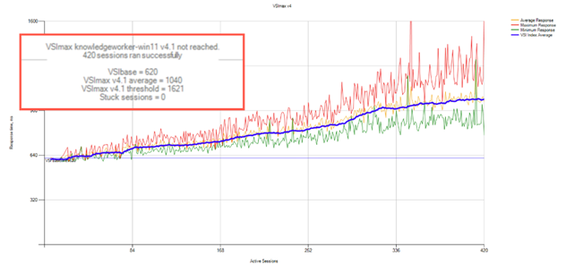
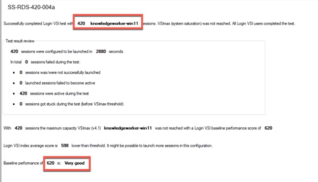
Performance data for the server running the workload as follows:

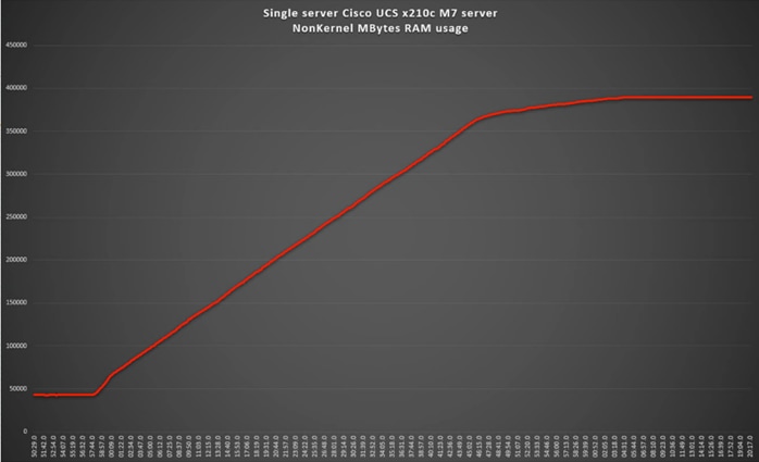
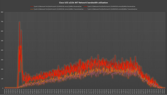
Single-Server Recommended Maximum Workload for VDI Non-Persistent with 325 Users
The Figure 52 illustrates single-server recommended maximum workload for VDI non-persistent with 325 users.
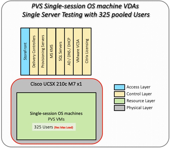
The recommended maximum workload for a Cisco UCS X210c M7Compute Node with dual INTEL processors, 2TB 4800MHz RAM is 325 Windows 11 64-bit virtual machines with 2 vCPU and 4GB RAM. Login VSI and node performance data as follows:
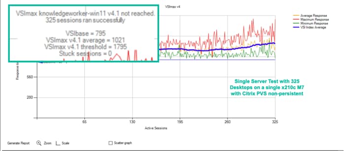
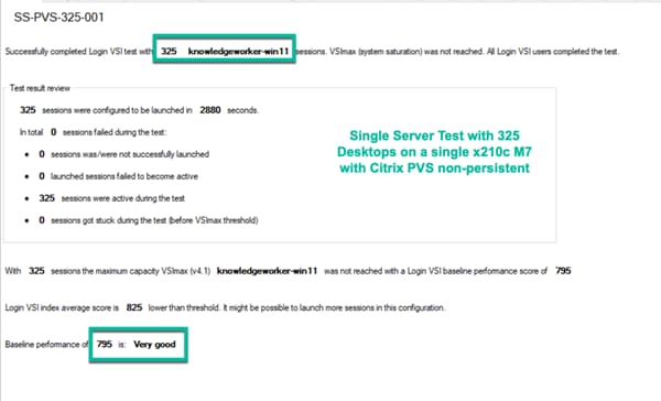
Performance data for the server running the workload as follows:
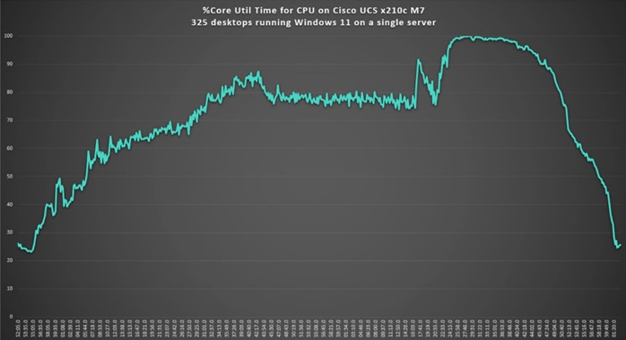
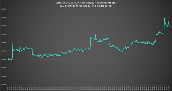
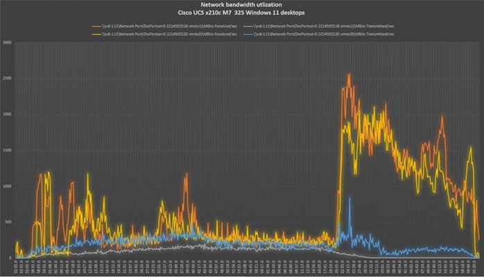
Single-Server Recommended Maximum Workload for VDI Persistent with 325 Users
The Figure 57 illustrates the single-server recommended maximum workload for VDI persistent with 325 users.
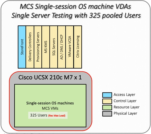
The recommended maximum workload for a Cisco UCS X210c M7Compute Node with dual INTEL processors, 2TB 4800MHz RAM is 325 Windows 11 64-bit virtual machines with 2 vCPU and 4GB RAM. Login VSI and Compute Node performance data as follows:
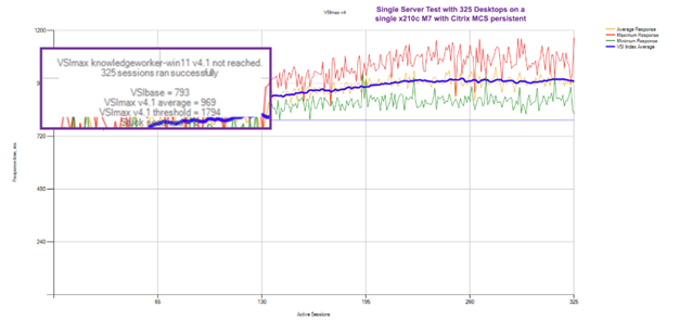
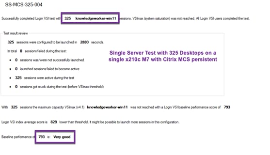
Performance data for the server running the workload as follows:
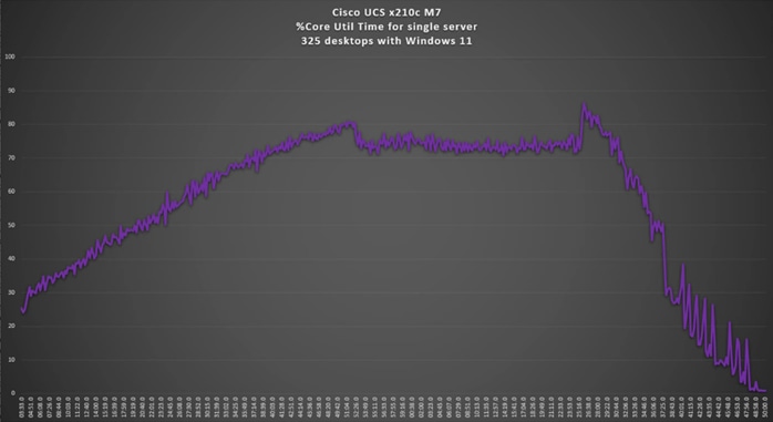
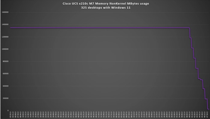
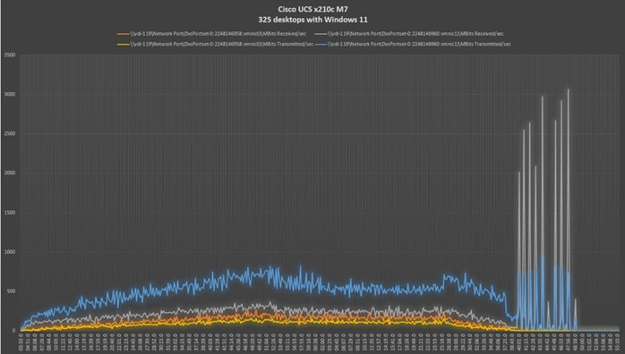
Full-Scale RDS Workload Testing with 2500 Users
This section shows the key performance metrics that were captured on the Cisco UCS, during the full-scale testing. The full-scale testing with users comprised of 2500 Hosted Shared Desktop Sessions using 8 compute nodes.
To achieve the target, sessions were launched against all workload clusters concurrently. As per the Cisco Test Protocol for VDI solutions, all sessions were launched within 48 minutes (using the official Knowledge Worker Workload in VSI Benchmark Mode) and all launched sessions became active within two minutes subsequent to the last logged in session.
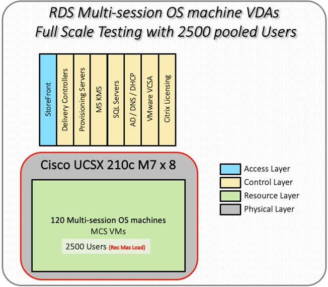
The configured system efficiently and effectively delivered the following results.
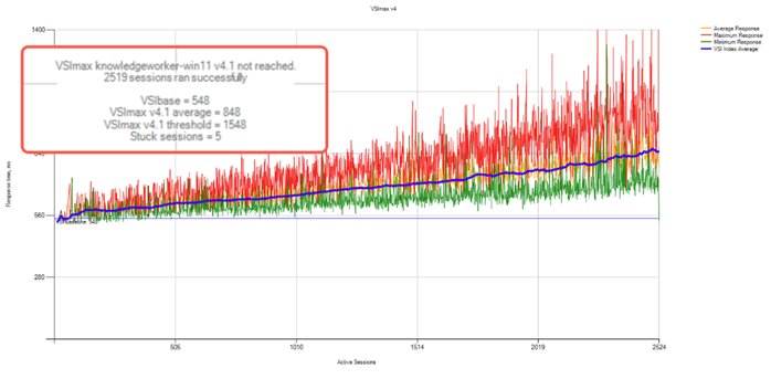
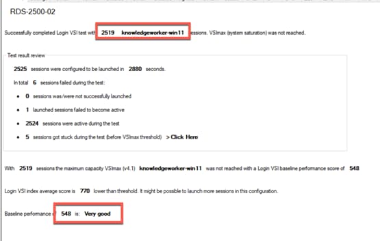
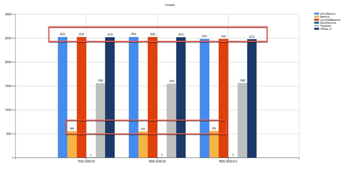

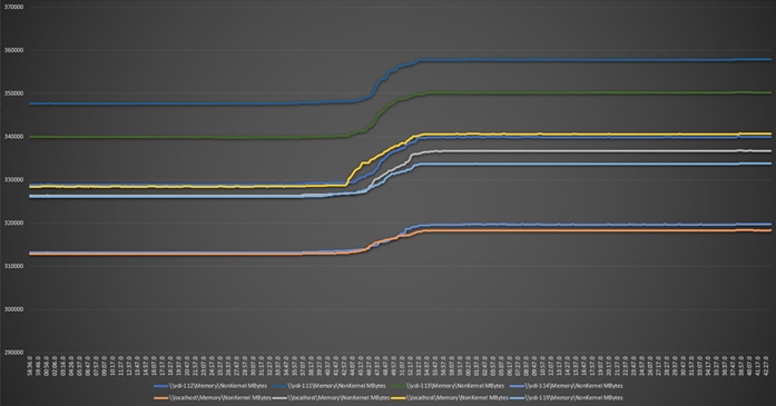
Full-Scale Non-Persistent Workload Testing with 2000 Users
This section shows the key performance metrics that were captured on the Cisco UCS, during the full-scale testing. The full-scale testing with 2000 users comprised of: 2000 Hosted Virtual Desktops using 8 compute nodes.
The combined mixed workload for the solution is 2000 users. To achieve the target, sessions were launched against all workload clusters concurrently. As per the Cisco Test Protocol for VDI solutions, all sessions were launched within 48 minutes (using the official Knowledge Worker Workload in VSI Benchmark Mode) and all launched sessions became active within two minutes subsequent to the last logged in session.

The configured system efficiently and effectively delivered the following results.
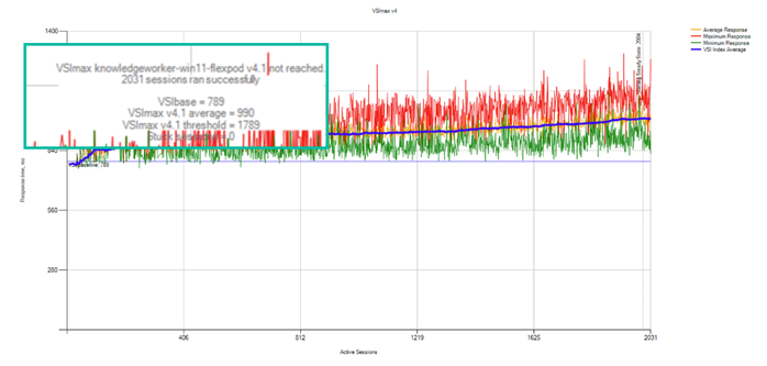
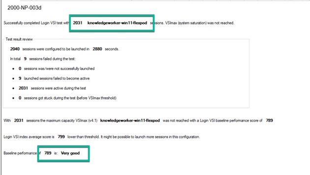
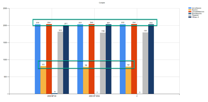
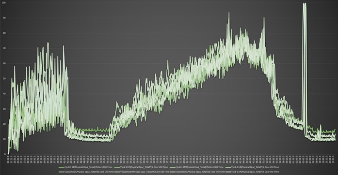

Full-Scale Persistent Workload Testing with 2000 Users
This section shows the key performance metrics that were captured on the Cisco UCS, during the full-scale testing. The full-scale testing with 2000 users comprised of: 2000 Persistent Hosted Virtual Desktop using 8 compute nodes.
The combined mixed workload for the solution is 2000 users. To achieve the target, sessions were launched against all workload clusters concurrently. As per the Cisco Test Protocol for VDI solutions, all sessions were launched within 48 minutes (using the official Knowledge Worker Workload in VSI Benchmark Mode) and all launched sessions became active within two minutes subsequent to the last logged in session.

The configured system efficiently and effectively delivered the following results.
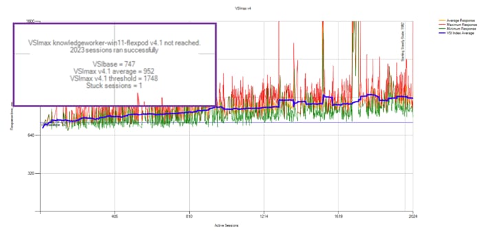
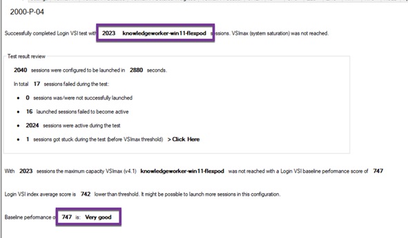
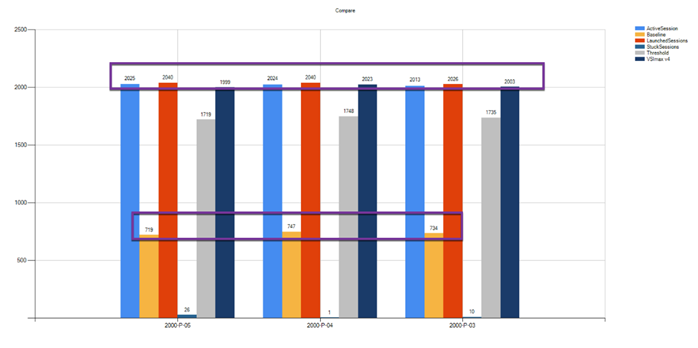
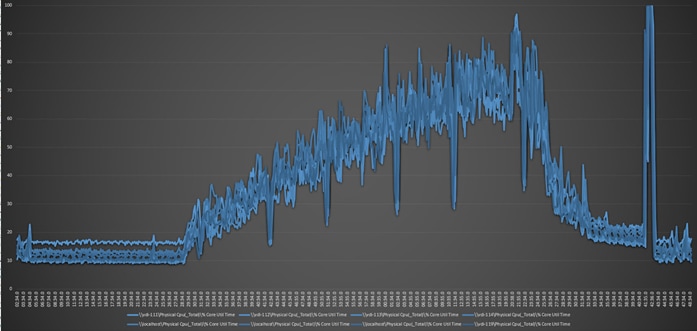
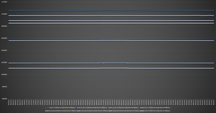
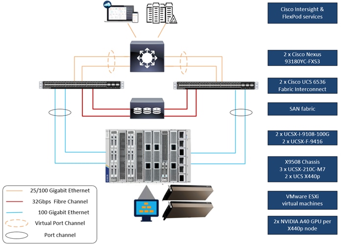
This solution includes NVIDIA GPUs utilizing the NVIDIA A40 cards running SPECviewperf 2020 workloads.
GPU Test workload included a single server with two A40 GPUs. Each Windows 11 machine had an 8GB NVIDIA Grid profile.
For NVIDIA Software installation and configuration guidance, refer to the NVIDIA documentation here: https://docs.nvidia.com/grid/13.0/grid-software-quick-start-guide/index.html
For guidance on installing and configuring NVIDIA GPUs in Cisco UCS X210c M7servers, refer to the Cisco documentation here: https://www.cisco.com/c/en/us/td/docs/unified_computing/ucs/c/hw/C245M7/install/c245M7/m_gpu-installation.html
For Cisco VDI best practices with GPU, refer to the VDI white papers the VDI team has produced, here: https://www.cisco.com/c/en/us/products/collateral/servers-unified-computing/ucs-x-series-modular-system/integrate-intersight-managed-ucs-x-series-wp.html and https://www.cisco.com/c/en/us/products/collateral/servers-unified-computing/ucs-c-series-rack-servers/ucs-m5-with-nvidia-and-citrix.html
The FlexPod on Cisco UCS X210c M7tested the effects of implementing two NVIDIA GPUs on an x440p PCI node in the cluster. Below are the test results for the SPECviewperf 2020 workload running with GPUs and Hardware Acceleration enabled for web surfing and productivity software. The end-user experience with high-end power users was positively impacted by having NVIDIA A40 GPUs in the solution.
Below are the SPECviewperf 2020 composite score results on hosts running Citrix VDI sessions with NVIDIA graphics acceleration enabled.
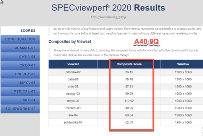
Using SPECviewperf 2020, we were able to measure the performance of NVIDIA GPUs in the Cisco UCS X210c M7 and show the outstanding Composite scores when running high end graphic-accelerated workstations on the FlexPod with Cisco UCS PCIe x440p nodes.
NetApp AFF A400 Storage Detailed Test Results for Cluster Scalability Test
This section provides analysis of the NetApp AFF A400 storage system performance results for each of the Citrix software module testing (HSD, PVS, Persistent), which we call cluster testing, and they are identified previously in this document. Specifically, it depicts and discusses the results for the following test case scenarios:
● 2500 Windows Server 2022 Citrix Hosted Shared desktops (RDS)
● 2000 Windows 11 x64 Citrix PVS Non-Persistent desktops
● 2000 Windows 11 x64 Citrix Persistent Full-Clone desktops
From a storage perspective, it is critical to maintain a latency of less than a millisecond for an optimal end-user experience no matter the IOPS and bandwidth being driven. The test results indicate that the AFF A400 storage delivers that essential minimum level of latency despite thousands of desktops hosted on the AFF A400 system.
The sections that follow show screenshots of the AFF A400 storage test data for all three use case scenarios with information about IOPS, bandwidth, and latency at the peak of each use case test. In all three use cases (cluster level testing with HSD PVS VDI, full clone persistent desktops and full-scale mixed workload sessions, the criteria followed prior to launching Login VSI workload test are the same
2500 Users Citrix HSD (RDS) Windows 2022 Sessions
This test uses Login VSI for the workload generator in Benchmark mode with the Knowledge Worker user type and with Citrix Remote Desktop Service Hosted (RDSH) sessions for the VDI delivery mechanism. For this test, we used 4 volumes. This test uses Citrix Cache on RAM feature which takes a lot of stress off of the storage, so you can see low IOPS for all the volumes in the following figures.
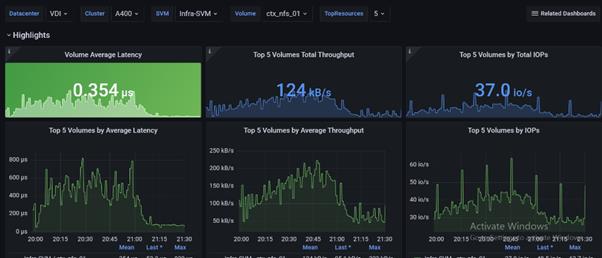
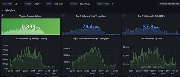
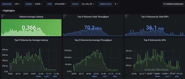
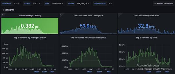
2000 Users Persistent Desktops Cluster Test
NetApp AFF A400 Test Results for 2000 Persistent Windows 11 x64 Citrix MCS Desktops
This section describes the key performance metrics that were captured on the NetApp Storage AFF A400 array during the testing with 2000 persistent desktops. For this test 4 volumes were used, and the average latency is below 1ms for all the volumes.
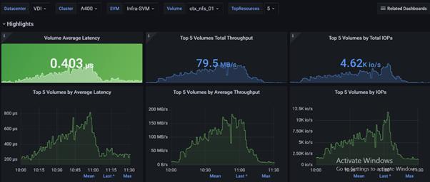
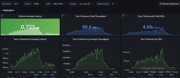
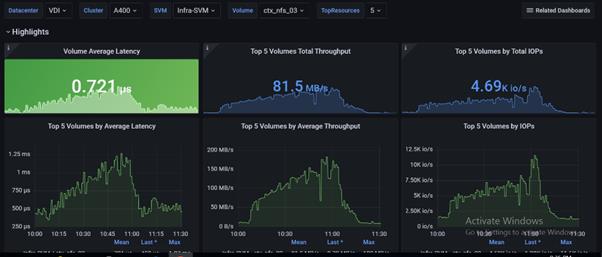
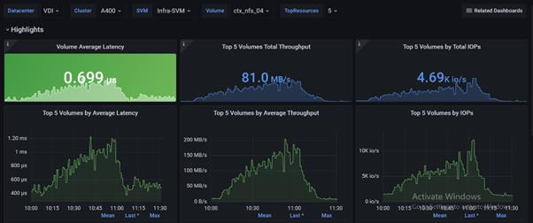
2000 Users PVS Non-Persistent Desktops Cluster Test
NetApp AFF A400 Test Results for 2000 Non-Persistent Windows 11 x64 Citrix MCS Desktops
For this test, 4 volumes were used, and the average latency is way below 1ms for all the volumes and the latency was not higher than 1ms at any time.

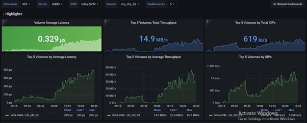
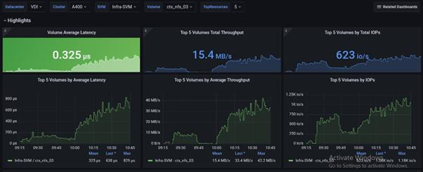

Scalability Considerations and Guidelines
There are many factors to consider when you begin to scale beyond 2500 Users, which this reference architecture has successfully tested. This 2500-seat solution provides a large-scale building block that can be replicated to confidently scale-out to tens of thousands of users.
As our results indicate, we have proven linear scalability in the Cisco UCS Reference Architecture as tested:
● Cisco UCS domains consist of a pair of Fabric Interconnects and a pair of chassis that can easily be scaled out with VDI growth.
● With Intersight, you get all of the benefits of SaaS delivery and full lifecycle management of distributed Intersight-connected servers and third-party storage across data centers, remote sites, branch offices, and edge environments. This empowers you to analyze, update, fix, and automate your environment in ways that were not possible with prior generations' tools. As a result, your organization can achieve significant TCO savings and deliver applications faster in support of new business initiatives.
● As scale grows, the value of the combined Cisco UCS fabric and Cisco Nexus physical switches increases dramatically to define the Quality of Services required to deliver excellent end user experience 100 percent of the time.
● To accommodate the Cisco Nexus 9000 upstream connectivity in the way we describe in the network configuration section, two Ethernet uplinks are needed to be configured on the Cisco UCS 6536 Fabric Interconnect.
The backend storage has to be scaled accordingly, based on the IOPS considerations as described in the NetApp scaling section. Please refer the NetApp section that follows this one for scalability guidelines.
NetApp AFF Storage Guidelines for Scale Desktop Virtualization Workloads
Storage sizing has three steps:
1. Gathering solution requirements.
2. Estimating storage capacity and performance.
3. Obtaining recommendations for the storage configuration.
Solution Assessment
Assessment is an important first step. Liquidware Labs Stratusphere FIT, and Lakeside VDI Assessment are recommended to collect network, server, and storage requirements. NetApp has contracted with Liquidware Labs to provide free licenses to NetApp employees and channel partners. For information on how to obtain software and licenses, refer to this FAQ. Liquidware Labs also provides a storage template that fits the NetApp system performance modeler. For guidelines on how to use Stratusphere FIT and the NetApp custom report template, refer to TR-3902: Guidelines for Virtual Desktop Storage Profiling.
Virtual desktop sizing depends on the following:
● The number of the seats
● The VM workload (applications, VM size, and VM OS)
● The connection broker (Citrix Virtual Apps and Desktops)
● The hypervisor type (vSphere, Citrix Hypervisor, or Hyper-V)
● The provisioning method (NetApp clone, Linked clone, PVS, and MCS)
● Future storage growth
● Disaster recovery requirements
● User home directories
NetApp has developed a sizing tool called the System Performance Modeler (SPM) that simplifies the process of performance sizing for NetApp systems. It has a step-by-step wizard to support varied workload requirements and provides recommendations for meeting your performance needs.
Storage sizing has two factors: capacity and performance. NetApp recommends using the NetApp SPM tool to size the virtual desktop solution. To use this tool, contact NetApp partners and NetApp sales engineers who have the access to SPM. When using the NetApp SPM to size a solution, NetApp recommends separately sizing the VDI workload (including the write cache and personal vDisk if used), and the CIFS profile and home directory workload. When sizing CIFS, NetApp recommends sizing with a heavy user workload. Eighty percent concurrency was assumed in this solution.
Capacity Considerations
Deploying Citrix Virtual Apps and Desktops with PVS imposes the following capacity considerations:
● vDisk. The size of the vDisk depends on the OS and the number of applications installed. It is a best practice to create vDisks larger than necessary in order to leave room for any additional application installations or patches. Each organization should determine the space requirements for its vDisk images. For example, a 20GB vDisk with a Windows 7 image is used. NetApp deduplication can be used for space savings.
● Write cache file. NetApp recommends a size range of 4 to 18GB for each user. Write cache size is based on what type of workload and how often the VM is rebooted. In this example, 4GB is used for the write-back cache. Since NFS is thin provisioned by default, only the space currently used by the VM will be consumed on the NetApp storage. If iSCSI or FCP is used, N x 4GB would be consumed as soon as a new virtual machine is created.
● PvDisk. Normally, 5 to 10GB is allocated, depending on the application and the size of the profile. Use 20 percent of the master image as a starting point. NetApp recommends running deduplication.
● CIFS home directory. Various factors must be considered for each home directory deployment. The key considerations for architecting and sizing a CIFS home directory solution include the number of users, the number of concurrent users, the space requirement for each user, and the network load. Run deduplication to obtain space savings.
● Infrastructure. Host Citrix Virtual Apps and Desktops, PVS, SQL Server, DNS, and DHCP.
The space calculation formula for a 2000-seat deployment is as follows: Number of vDisk x 20GB + 2000 x 4GB write cache + 2000 x 10GB PvDisk + 2000 x 5GB user home directory x 70% + 500 x 1GB vSwap + 500GB infrastructure.
Performance Considerations
The collection of performance requirements is a critical step. After using Liquidware Labs Stratusphere FIT and Lakeside VDI Assessment to gather I/O requirements, contact the NetApp account team to obtain recommended software and hardware configurations.
Size, the read/write ratio, and random or sequential reads comprise the I/O considerations. We use 90 percent write and 10 percent read for PVS workload. Storage CPU utilization must also be considered. Table 22 can be used as guidance for your sizing calculations for a PVS workload when using a LoginVSI heavy workload.
Table 22. Typical IOPS without RAM Cache plus Overflow Feature
|
|
Boot IOPS |
Login IOPS |
Steady IOPS |
| Write Cache (NFS) |
8-10 |
9 |
7.5 |
| vDisk (CIFS SMB 3) |
0.5 |
0 |
0 |
| Infrastructure (NFS) |
2 |
1.5 |
0 |
Scalability of Citrix Virtual Apps and Desktops 7 LTSR Configuration
Citrix Virtual Apps and Desktops environments can scale to large numbers. When implementing Citrix Virtual Apps and Desktops, consider the following in scaling the number of hosted shared and hosted virtual desktops:
● Types of storage in your environment
● Types of desktops that will be deployed
● Data protection requirements
● For Citrix Provisioning Server pooled desktops, the write cache sizing and placement
When designing and deploying this CVD environment Cisco and Citrix recommends using N+1 schema for virtualization host servers to accommodate resiliency. In all Reference Architectures (such as this CVD), this recommendation is applied to all host servers.
Hybrid Cloud Disaster Recovery Testing and Results
Cloud computing has clearly been one of the most disruptive IT trends of recent times. With the undeniable benefits of cloud computing, many enterprises are now moving aggressively towards a cloud first strategy. While the benefits of public cloud have been proven for certain workloads and use cases, there is growing acknowledgement of its trade-offs in areas such as availability, performance, customization, and security. To overcome these public cloud challenges, organizations are adopting hybrid cloud models that offer enterprises a more cohesive approach to adopt cloud computing. A hybrid cloud model gives organizations the flexibility to leverage the right blend of public and private cloud services, while addressing the availability, performance, and security challenges
FlexPod Datacenter for Hybrid Cloud delivers a validated FlexPod infrastructure design that allows you to utilize resources in the public cloud based on the organization workload deployment policies or when the workload demand exceeds the available resources in the Datacenter. The VDI FlexPod Datacenter for Hybrid Cloud showcases:
● Citrix Virtual Apps and Desktops in the Citrix Cloud
● Data Replication and backup with NetApp Cloud ONTAP
● VDI redundancy using virtual machines in Microsoft Azure
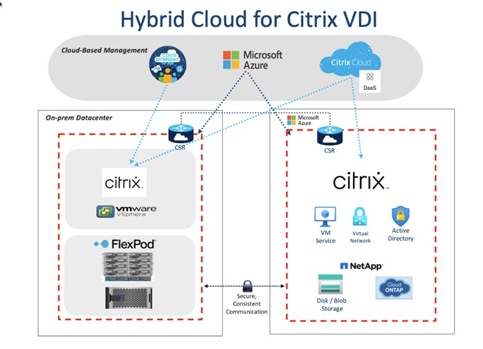
In this disaster recovery solution, Citrix Cloud was used for the VDI components. NetApp BlueXP and CVO were used to protect the on-premise data and virtual machines. Finally, Microsoft Azure was used to ensure the infrastructure capabilities in the cloud, such as Active Directory, SQL, DNS, and Virtual Machines. In this solution, disaster recovery was implemented and tested. To perform the validation of a successful DR scenario, first move data from a volume in ONTAP that is part of FlexPod to Cloud Volumes ONTAP using SnapMirror, then you can access the data from the Microsoft Azure cloud compute instance followed by a data integrity check.
Procedure 1. Verify the success criteria of this solution
Step 1. Create a NFS mount on an On-prem linux machine and add a sample dataset in the mount directory.
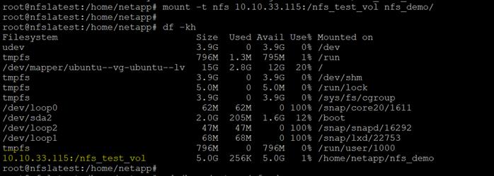
Step 2. Generate an SHA256 checksum on the sample dataset that is present in an ONTAP volume in FlexPod.

Step 3. Set up a volume SnapMirror relationship between ONTAP in FlexPod and Cloud Volumes ONTAP.
Step 4. Replicate the sample dataset from FlexPod to Cloud Volumes ONTAP.
Step 5. Break the SnapMirror relationship and promote the volume in Cloud Volumes ONTAP to production.
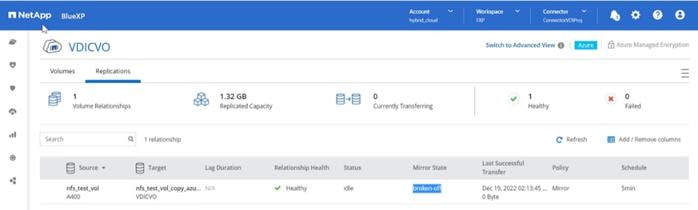
Step 6. Edit the Cloud volume ONTAP volume and modify the custom export policy.
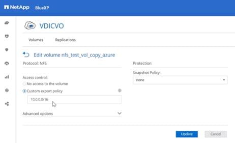
Step 7. Copy the mount command.
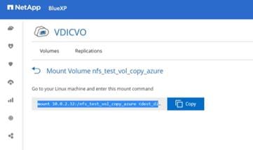
Step 8. Map the Cloud Volumes ONTAP volume with the dataset to a compute instance in Microsoft Azure.
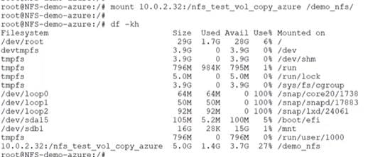
Step 9. Generate an SHA256 checksum on the sample dataset in Cloud Volumes ONTAP.
Step 10. Compare the checksum on the source and destination; presumably, the checksums on both sides match.
The entire Cisco solution for VDI on FlexPod was deployed and managed on Cisco Intersight. All policies and profiles were deployed using tried and true best practices for VDI on Cisco UCS systems.
Citrix Cloud is a platform that hosts and administers Citrix cloud services. It connects to your resources through connectors on any cloud or infrastructure you choose (on-premises, public cloud, private cloud, or hybrid cloud). It allows you to create, manage, and deploy workspaces with apps and data to your end-users from a single console.
To learn more about key service components in Citrix Cloud, see the following resources:
● Citrix Workspace conceptual diagram: Provides an overview of key areas such as identity, workspace intelligence, and single sign-on.
● Reference Architectures: Provides comprehensive guides for planning your Citrix Workspace implementation, including use cases, recommendations, and related resources.
● Citrix DaaS reference architectures: Provides in-depth guidance for deploying Citrix DaaS (formerly Virtual Apps and Desktops service) with related services.
With this test, the Citrix Cloud was configured to run on-premise virtual desktops for user access. For more information, see https://docs.citrix.com/en-us/tech-zone/learn/poc-guides/cvads.html
For the users to have desktops available in the event of an on-premise failure, the Citrix desktops were configured in the Microsoft Azure tenant, to copy the user data and virtual machines using ONTAP. For more information, see https://docs.citrix.com/en-us/citrix-daas-azure.html
Microsoft Azure and Citrix Cloud
Procedure 1. Solution Steps
Step 1. Configure Azure Active Directory to enable directory services are consistent.
Step 2. Create Public IP for the CSR/VPN gateway.
Step 3. Configure on-prem subnets in the Azure Local Network Gateway.
Step 4. Configure subnets for Azure resource use to create the Virtual Network Gateway and creating Azure based subnets.
Step 5. Create a site to site VPN with Cisco CSR to connect the on-premise resources with Azure resources.
Step 6. Test two way connectivity between on-prem subnets and Azure subnets.
Step 7. Build virtual machines in Azure with software and Citrix image.
Step 8. In Citrix Cloud create hosting connection and catalog to Microsoft Azure.
Step 9. Add on-prem and cloud VMs to a single desktop delivery group
For more information, see https://docs.citrix.com/en-us/citrix-daas-azure/catalogs-create.html#creating-catalogs-of-azure-ad-domain-joined-machines
When the on-premise desktops are no longer available, the Microsoft Azure-based desktops will power on and register with the delivery group. You will be able to access their corporate desktops while their data and files are being replicated using NetApp’s Cloud technology previously described.
FlexPod delivers a platform for enterprise end user computing deployments and cloud data centers using Cisco UCS Compute Node and Rack Servers, Cisco fabric interconnects, Cisco Nexus 9000 switches, Cisco MDS 9100 fibre channel switches and NetApp Storage AFF A400 Storage Array. FlexPod is designed and validated using compute, network and storage best practices and high availability to reduce deployment time, project risk and IT costs while maintaining scalability and flexibility for addressing a multitude of IT initiatives. This CVD validates the design, performance, management, scalability, and resilience that FlexPod provides to customers wanting to deploy enterprise-class VDI.
Jeff Nichols—Leader, Technical Marketing, CSPG UCS Solutions – US, Cisco Systems, Inc.
Jeff is a subject matter expert on desktop and server virtualization, Cisco HyperFlex, Cisco Unified Computing System, Cisco Nexus Switching, and NVIDIA/AMD Graphics.
Ruchika Lahoti—Technical Marketing Engineer, NetApp
Ruchika has more than five years of experience in the IT industry. She focuses on FlexPod hybrid cloud infrastructure solution design, implementation, validation, automation. Ruchika earned a bachelor’s degree in Computer Science.
For their support and contribution to the design, validation, and creation of this Cisco Validated Design, the authors would like to thank:
● Bobby Oommen–Manager, Technical Marketing, NetApp
This section provides links to additional information for each partner’s solution component of this document.
Cisco Intersight Configuration Guides
● https://intersight.com/help/saas/supported_systems#supported_hardware_for_intersight_managed_mode
Cisco Nexus Switching References
● http://www.cisco.com/c/en/us/products/switches/nexus-N9K-C93180YC-FX3S -switch/index.html
Cisco MDS 9000 Service Switch References
● http://www.cisco.com/c/en/us/products/storage-networking/product-listing.html
● https://docs.citrix.com/en-us/citrix-virtual-apps-desktops/7-ltsr.html
● https://docs.citrix.com/en-us/provisioning/7-ltsr.html
● https://support.citrix.com/article/CTX216252?recommended
● https://support.citrix.com/article/CTX224676
● https://support.citrix.com/article/CTX117374
● https://support.citrix.com/article/CTX202400
● https://support.citrix.com/article/CTX210488
FlexPod
● https://www.cisco.com/c/en/us/td/docs/unified_computing/ucs/UCS_CVDs/flexpod_esxi65u1_n9fc.html
● https://docs.vmware.com/en/VMware-vSphere/index.html
● https://labs.vmware.com/flings/vmware-os-optimization-tool
● https://technet.microsoft.com/en-us/library/hh831620(v=ws.11).aspx
● https://technet.microsoft.com/en-us/library/dn281793(v=ws.11).aspx
● https://support.microsoft.com/en-us/kb/2833839
● https://technet.microsoft.com/en-us/library/hh831447(v=ws.11).aspx
● https://www.loginvsi.com/documentation/Main_Page
● https://www.loginvsi.com/documentation/Start_your_first_test
● http://www.netapp.com/us/products/storage-systems/all-flash-array/aff-a-series.aspx
● http://www.netapp.com/us/products/data-management-software/ontap.aspx
● https://mysupport.netapp.com/documentation/docweb/index.html?productID=62379&language=en-US
● http://www.netapp.com/us/products/management-software/
● http://www.netapp.com/us/products/management-software/vsc/
Appendix A: Build of Materials for Cisco Components
Table 23 lists the bill of materials for the Cisco components.

For comments and suggestions about this guide and related guides, join the discussion on Cisco Community at https://cs.co/en-cvds.
CVD Program
ALL DESIGNS, SPECIFICATIONS, STATEMENTS, INFORMATION, AND RECOMMENDATIONS (COLLECTIVELY, "DESIGNS") IN THIS MANUAL ARE PRESENTED "AS IS," WITH ALL FAULTS. CISCO AND ITS SUPPLIERS DISCLAIM ALL WARRANTIES, INCLUDING, WITHOUT LIMITATION, THE WARRANTY OF MERCHANTABILITY, FITNESS FOR A PARTICULAR PURPOSE AND NONINFRINGEMENT OR ARISING FROM A COURSE OF DEALING, USAGE, OR TRADE PRACTICE. IN NO EVENT SHALL CISCO OR ITS SUPPLIERS BE LIABLE FOR ANY INDIRECT, SPECIAL, CONSEQUENTIAL, OR INCIDENTAL DAMAGES, INCLUDING, WITHOUT LIMITATION, LOST PROFITS OR LOSS OR DAMAGE TO DATA ARISING OUT OF THE USE OR INABILITY TO USE THE DESIGNS, EVEN IF CISCO OR ITS SUPPLIERS HAVE BEEN ADVISED OF THE POSSIBILITY OF SUCH DAMAGES.
THE DESIGNS ARE SUBJECT TO CHANGE WITHOUT NOTICE. USERS ARE SOLELY RESPONSIBLE FOR THEIR APPLICATION OF THE DESIGNS. THE DESIGNS DO NOT CONSTITUTE THE TECHNICAL OR OTHER PROFESSIONAL ADVICE OF CISCO, ITS SUPPLIERS OR PARTNERS. USERS SHOULD CONSULT THEIR OWN TECHNICAL ADVISORS BEFORE IMPLEMENTING THE DESIGNS. RESULTS MAY VARY DEPENDING ON FACTORS NOT TESTED BY CISCO.
CCDE, CCENT, Cisco Eos, Cisco Lumin, Cisco Nexus, Cisco StadiumVision, Cisco TelePresence, Cisco WebEx, the Cisco logo, DCE, and Welcome to the Human Network are trademarks; Changing the Way We Work, Live, Play, and Learn and Cisco Store are service marks; and Access Registrar, Aironet, AsyncOS, Bringing the Meeting To You, Catalyst, CCDA, CCDP, CCIE, CCIP, CCNA, CCNP, CCSP, CCVP, Cisco, the Cisco Certified Internetwork Expert logo, Cisco IOS, Cisco Press, Cisco Systems, Cisco Systems Capital, the Cisco Systems logo, Cisco Unified Computing System (Cisco UCS), Cisco UCS B-Series Blade Servers, Cisco UCS C-Series Rack Servers, Cisco UCS S-Series Storage Servers, Cisco UCS X-Series, Cisco UCS Manager, Cisco UCS Management Software, Cisco Unified Fabric, Cisco Application Centric Infrastructure, Cisco Nexus 9000 Series, Cisco Nexus 7000 Series. Cisco Prime Data Center Network Manager, Cisco NX-OS Software, Cisco MDS Series, Cisco Unity, Collaboration Without Limitation, EtherFast, EtherSwitch, Event Center, Fast Step, Follow Me Browsing, FormShare, GigaDrive, HomeLink, Internet Quotient, IOS, iPhone, iQuick Study, LightStream, Linksys, MediaTone, MeetingPlace, MeetingPlace Chime Sound, MGX, Networkers, Networking Academy, Network Registrar, PCNow, PIX, PowerPanels, ProConnect, ScriptShare, SenderBase, SMARTnet, Spectrum Expert, StackWise, The Fastest Way to Increase Your Internet Quotient, TransPath, WebEx, and the WebEx logo are registered trade-marks of Cisco Systems, Inc. and/or its affiliates in the United States and certain other countries. (LDW_P3)
All other trademarks mentioned in this document or website are the property of their respective owners. The use of the word partner does not imply a partnership relationship between Cisco and any other company. (0809R)