Scaling FlexPod for GPU Intensive Applications
Available Languages
Bias-Free Language
The documentation set for this product strives to use bias-free language. For the purposes of this documentation set, bias-free is defined as language that does not imply discrimination based on age, disability, gender, racial identity, ethnic identity, sexual orientation, socioeconomic status, and intersectionality. Exceptions may be present in the documentation due to language that is hardcoded in the user interfaces of the product software, language used based on RFP documentation, or language that is used by a referenced third-party product. Learn more about how Cisco is using Inclusive Language.
- US/Canada 800-553-2447
- Worldwide Support Phone Numbers
- All Tools
 Feedback
 Feedback

In partnership with:
![]()
About the Cisco Validated Design Program
The Cisco Validated Design (CVD) program consists of systems and solutions designed, tested, and documented to facilitate faster, more reliable, and more predictable customer deployments. For more information, go to: http://www.cisco.com/go/designzone.
Organizations across various industries are facing challenges in overcoming competitive pressures, improve quality, boost productivity, accelerate digital transformation and decrease time to market, costs, and risks. The exponential growth in data is propelling the adoption of GPU Intensive Applications, HPC and AI technologies across multiple domains, as organizations seek to harness the power of these tools to extract meaningful insights, drive innovation, and make data-driven decisions in an increasingly data-rich world.
The definition of HPC (High-Performance Computing) is constantly changing, traditionally focused on transports that are sensitive to latency and the highest level of parallelization. GPUs take this evolution a step further. These advancements are enhanced by the amalgamation of GPU-accelerated applications and AI, leading to significant breakthroughs in various fields such as healthcare, finance, materials science, and climate research. This fusion allows researchers to delve into more complex models, simulate real-world scenarios, and analyze large datasets for data-driven discoveries. To fully leverage these capabilities and reap maximum benefits, a well-balanced and high-performing infrastructure encompassing compute, network, and storage is necessary. FlexPod facilitates this comprehensive approach.
AI has made a significant impact by transforming how the IT systems and services are developed, managed, and utilized. Adoption of AI-native infrastructure includes hardware accelerators such as GPU (Graphics Processing Unit), FPGA (Field Programmable Gate Arrays) and Tensor Processing Units (TPU) to handle AI computation effectively at scale. capable of extracting insights, learning from data patterns, and generating predictions, and making intelligent decisions, all at a scale and speed previously unattainable. Convergence of HPC and AI are reshaping the future datacenter design paradigm.
The convergence of GPU Intensive Applications, High-Performance Computing (HPC) and Artificial Intelligence (AI) technologies in a unified architecture brings about enhanced performance, scalability, and versatility for data-intensive tasks. This integration seamlessly incorporates popular AI development frameworks like TensorFlow and PyTorch, allowing data scientists and researchers to develop, train, and deploy AI models within the HPC environment. The fusion of custom solutions, hyperparameter optimization, and cross-validation enables the fine-tuning of models, empowering the exploration of complex scenarios and analysis of vast datasets in fields such as healthcare, finance, materials science, and climate research. Groundbreaking advancements are evident in applications like climate modeling, weather prediction, finance (risk analysis and fraud detection), energy exploration, material science, and healthcare (drug discovery and patient care).
While challenges exist, addressing them through strategic approaches involving talent development, best practices, robust data governance, and awareness of evolving technologies and regulations can unlock the transformative benefits of HPC and AI integration. This collaborative approach fosters improved decision-making, scientific advancements, and innovation across diverse industries and research domains.
This document summarizes SpecHPC 2021 based benchmark applications targeted for real-life model simulation in the fields of but not limited to; linear scalability when executing various size of dataset on HPC cluster consisting of eight node Cisco UCS C240 M7 Rack Server hosting NVIDIA A100-80G GPUs in FlexPod architecture.
● Weather simulation – Weather forecasting and climate modeling, agriculture, aviation, natural disaster prediction and prevention, renewable energy.
● Nuclear engineering (radiation transport) – Nuclear energy, radiation shielding, nuclear security and safeguards, medical imaging, and treatment.
● High performance geometric multigrid – Biomedical simulation, oil and gas reservoir simulation, Fluid Dynamics and Aerodynamics, structural mechanics.
FlexPod is designed to meet the demands of AI workloads. It offers:
● Simplified deployment and operation of general-purpose AI workloads.
● Seamless integration into AI eco systems.
● Gain operational simplicity and efficiency.
● Accelerate time to value and speed up AI implementation.
● Protect AI infra to safeguard systems, management, data, and applications.
● Linear Scalability: Demonstrated through benchmark tests, showcasing consistent performance even with varying dataset sizes.
● Centralized Management and Automation: Powered by Cisco Intersight, FlexPod reduces deployment times, optimizes resource utilization, minimizes energy consumption, and streamlines operations.
● NVIDIA HPC-X Software Toolkit Setup and Configuration: We've validated FlexPod using the NVIDIA HPC-X software toolkit, ensuring seamless integration and optimal performance. This toolkit harnesses the power of technologies like MPI (Message Passing Interface), OpenACC (Open Accelerators), and UCX (Unified Communication X) to enhance the capabilities of our solution.
● NetApp Tools: NetApp DataOps Toolkit is a Python library that makes it easy for developers, data scientists, and data engineers to perform numerous data management tasks.
● Comprehensive Testing for Real-World Workloads: Our rigorous testing process evaluates the scalability of FlexPod across different dataset sizes and application areas. We compare CPU-only performance with GPU-equipped systems, providing valuable insights into the capabilities of our solution.
The pre-validated design of FlexPod with centralized management and automation capabilities of Cisco Intersight reduces deployment times, optimize resource utilization, minimize energy consumption, and streamlining operations leading to better TCO (Total Cost of Ownership) and improved ROI (Return on Investment).
This chapter contains the following:
● Audience
The FlexPod AI (Artificial Intelligence) solution for HPC and AI workloads aims to deliver a seamless integration of the current FlexPod portfolio to enable single architecture which can be sized and optimized for GPU acceleration and faster access to data through high-speed data-fabric.
This document describes steps to install and configure the Cisco UCS C240 M7 Rack Server with NVIDIA GPU in FlexPod AI. The deployment details can be extended on the Cisco UCS server with supported NVIDIA GPUs such as Cisco UCS C22X M7, C24X M7 and Cisco UCS X210c compute nodes with X440p PCIe node within the FlexPod AI.
Audience
The intended audience for this document includes, but is not limited to, sales engineers, field consultants, professional services, IT managers, IT engineers, partners, and customers who wants to take advantage of an infrastructure catering diverse workload HPC, AI/ML and analytics in a single architecture and be able to deliver IT efficiency and enable IT innovation.
This document serves as a comprehensive guide for integrating the Cisco Intersight-managed Cisco UCS M7 servers into the FlexPod AI infrastructure. It provides essential design guidance, covering various elements and considerations necessary for a successful deployment. This document highlights the significant value of horizontal scaling in accelerating applications through the addition of GPU and CPU resources. Horizontal scaling enables organizations to harness the power of multiple GPUs and CPUs, unlocking enhanced processing capabilities and improved performance for AI/ML workloads. By leveraging the scalability of the Cisco UCS M7 servers, businesses can achieve optimal utilization of computational resources and drive breakthroughs in fields that demand intensive computing power. Additionally, this document emphasizes the design and product requirements for incorporating scalable AI/ML solutions to address high-performance computing use cases, including weather modeling, high energy physics, scientific experiment simulation, and life sciences.
Furthermore, through the integration of Cisco Intersight management and the FlexPod AI infrastructure, this document provides valuable insights into the best practices and considerations for deploying a scalable and high-performing solution. It empowers organizations to leverage advanced technologies and accelerate their AI/ML initiatives, ultimately driving innovation and achieving transformative results in their respective industries.
The following design elements distinguish this version of FlexPod from previous models:
● Optimized integration of Cisco UCS C240 M7 servers with NVIDIA A100 GPU into the platform design.
● Scalable HPC cluster with GPU (Nvidia A100) and CPU (Intel 4th gen scalable processors) based practices.
● Support for 4th Gen Intel Xeon Scalable Processors (Sapphire Rapids) with up to 60 cores per processor and up to 8TB memory with 32 x 256GB DDR5-4800 DIMMs.
● Integration of NetApp A400 NVMe based all flash storage system to support AI/ML dataset.
● NetApp ONTAP 9.12.1.
● FlexPod AI architecture with end-to-end 100Gbps.
● Cisco Intersight managed stand-alone UCS C-Series rack server connected to Cisco Nexus switch.
● Cisco Intersight automated operating system installation.
● Ansible for post-OS configuration of HPC-AI cluster on bare metal.
The FlexPod AI solution offers the following key benefits:
● Converged Infrastructure: FlexPod provides a pre-validated and integrated solution that combines compute, storage, and networking components, streamlining deployment and management.
● Modular Scalability: With its modular architecture, FlexPod allows for the independent scaling of resources, enabling organizations to adapt to changing workload demands.
● Simplified Management: FlexPod includes management and orchestration tools that automate provisioning and ensure consistent and compliant infrastructure management.
● Multitenancy Support: It offers multitenancy capabilities, allowing multiple workloads or applications to run concurrently while maintaining isolation and security.
● Compatibility Assurance: Cisco and NetApp certification processes ensure that all components are compatible and reliable, reducing the risk of integration issues and providing stable and supported infrastructure.
● Investment protection: as technology evolves, businesses can add new components or upgrade existing ones to adapt to changing workload demands while maintaining the integrity of their initial investment in FlexPod.
This chapter contains the following:
● Cisco Unified Computing System
● Cisco UCS C-Series Rack Server
FlexPod AI
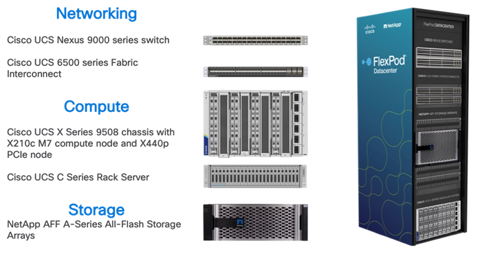
FlexPod is an integrated data center solution that combines compute, storage, and networking components, simplifying deployment, and offering scalability. It ensures compatibility and supports multiple workloads, making it an efficient and adaptable choice for modern data centers.
Go to the Cisco Design Zone for pre-validated FlexPod Design Guides containing a wide variety of enterprise applications.
Cisco Unified Computing System
Cisco Unified Computing System (Cisco UCS) is a next-generation data center platform that integrates compute, network, storage, and virtualization resources into a single cohesive architecture simplifying data center management, improved operational efficiency, reduce total cost of ownership, and increase business agility.
Cisco UCS Manager is the central management software that provides a unified interface for configuring, monitoring, and automating the entire UCS infrastructure, streamlining operations and enabling rapid resource provisioning. Cisco Intersight is a cloud-based management platform that offers enhanced visibility, analytics, and automation for Cisco UCS and other Cisco infrastructure, providing a scalable and intelligent solution for optimizing data center operations and achieving agility in the modern IT landscape.
Cisco Unified Computing System is revolutionizing the way servers are managed in the datacenter. The following are the unique differentiators of Cisco Unified Computing System and Cisco UCS Manager:
● Embedded Management—In Cisco UCS, the servers are managed by the embedded firmware in the Fabric Inter-connects, eliminating the need for any external physical or virtual devices to manage the servers.
● Unified Fabric—In Cisco UCS, from blade server chassis or rack servers to FI, there is a single Ethernet cable used for LAN, SAN, and management traffic. This converged I/O results in reduced cables, SFPs and adapters – reducing capital and operational expenses of the overall solution.
● Auto Discovery—By simply inserting the blade server in the chassis or connecting the rack server to the fabric interconnect, discovery and inventory of compute resources occurs automatically without any management intervention. The combination of unified fabric and auto-discovery enables the wire-once architecture of Cisco UCS, where compute capability of Cisco UCS can be extended easily while keeping the existing external connectivity to LAN, SAN, and management networks.
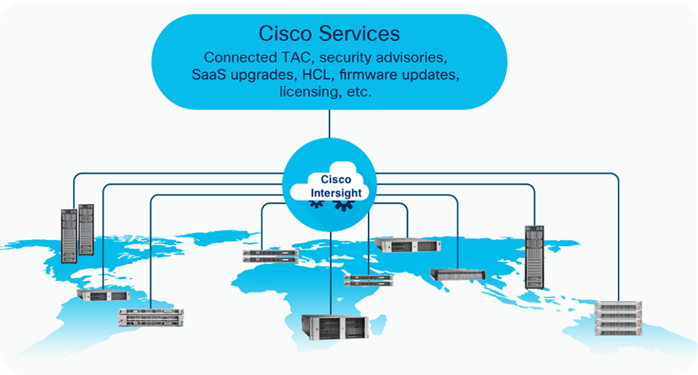
Cisco Intersight is a lifecycle management platform for your infrastructure, regardless of where it resides. In your enterprise data center, at the edge, in remote and branch offices, at retail and industrial sites—all these locations present unique management challenges and have typically required separate tools. Cisco Intersight Software as a Service (SaaS) unifies and simplifies your experience of the Cisco Unified Computing System (Cisco UCS). See Figure 2.
Cisco UCS C-Series Rack Server
Cisco UCS C-Series Rack-Mount Servers keep pace with Intel Xeon and AMD EPYC processor innovation by offering the latest processors with increased processor frequency and improved security and availability features. Cisco UCS C-Series servers offer an improved price-to-performance ratio. They also extend Cisco UCS innovations to an industry-standard rack-mount form factor, including a standards-based unified network fabric, Cisco VN-Link virtualization support, and Cisco Extended Memory Technology.
It is designed to operate both in standalone environments and as part of Cisco UCS managed by Cisco Intersight or Cisco UCS Manager. Cisco UCS C-Series servers enable organizations to deploy systems incrementally—using as many or as few servers as needed—on a schedule that best meets the organization’s timing and budget.
Cisco UCS C240 M7 Rack Server
The Cisco UCS C240 M7 Rack Server extends the capabilities of the Cisco UCS rack server portfolio with up to two 4th Gen Intel Xeon Scalable CPUs, with up to 60 cores per socket. The maximum memory capacity for 2 CPUs is 8 TB (for 32 x 256 GB DDR5 4800 MT/s DIMMs). The Cisco UCS C240 M7 has a 2-Rack-Unit (RU) form and supports up to 8 PCIe 4.0 slots or up to 4 PCIe 5.0 slots plus a modular LAN on motherboard (mLOM) slot. Up to five GPUs are supported. The server delivers significant performance and efficiency gains that will improve your application performance.
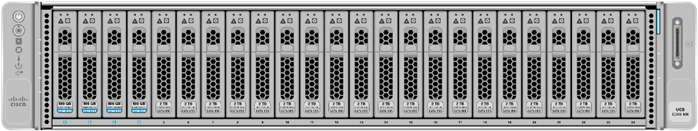
For more details, go to: Cisco UCS C240 M7 Rack Server Data Sheet.
Based on Cisco Cloud Scale technology, the Cisco Nexus 9300-GX switches are the next generation of fixed Cisco Nexus 9000 Series Switches capable of supporting 400 Gigabit Ethernet (GE). With the increase in use cases for applications requiring Artificial Intelligence (AI) and Machine Learning (ML), the platform addresses the need for high-performance, power-efficient, compact switches in the networking infrastructure. These switches are designed to support 100G and 400G fabrics for mobile service provider environments, including the network edge, 5G, IoT, Professional Media Networking platform (PMN), and Network Functions Virtualization (NFV).
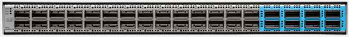
The Cisco Nexus 93600CD-GX Switch (Figure 2) is a 1RU switch that supports 12 Tbps of bandwidth and 4.0 bpps across 28 fixed 40/100G QSFP-28 ports and 8 fixed 10/25/40/50/100/200/400G QSFP-DD ports.
Cisco provides two modes of operation for Cisco Nexus 9000 Series Switches. Organizations can deploy Cisco Application Centric Infrastructure (Cisco ACI) or Cisco NX-OS mode.
For more details, see https://www.cisco.com/c/en/us/products/collateral/switches/nexus-9000-series-switches/nexus-9300-gx-series-switches-ds.html
NetApp AFF A-Series controller lineup provides industry leading performance while continuing to provide a full suite of enterprise-grade data management and data protection features. NetApp AFF A-Series systems support end-to-end NVMe technologies, from NVMe-attached SSDs to frontend NVMe over Fibre Channel (NVMe/FC) host connectivity. These systems deliver enterprise class performance, making them a superior choice for driving the most demanding workloads and applications. With a simple software upgrade to the modern NVMe/FC SAN infrastructure, you can drive more workloads with faster response times, without disruption or data migration. Additionally, more organizations are adopting a “cloud first” strategy, driving the need for enterprise-grade data services for a shared environment across on-premises data centers and the cloud. As a result, modern all-flash arrays must provide robust data services, integrated data protection, seamless scalability, and new levels of performance — plus deep application and cloud integration. These new workloads demand performance that first-generation flash systems cannot deliver.
For more information about the NetApp AFF A-series controllers, see the AFF product page: https://www.netapp.com/us/products/storage-systems/all-flash-array/aff-a-series.aspx.
You can view or download more technical specifications of the NetApp AFF A-series controllers here: https://www.netapp.com/us/media/ds-3582.pdf
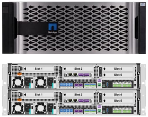
NetApp AFF A400
The NetApp AFF A400 offers full end-to-end NVMe support. The frontend NVMe/FC connectivity makes it possible to achieve optimal performance from an all-flash array for workloads that include artificial intelligence, machine learning, and real-time analytics as well as business-critical databases. On the back end, the A400 supports both serial-attached SCSI (SAS) and NVMe-attached SSDs, offering the versatility for current customers to move up from their legacy A-Series systems and satisfying the increasing interest that all customers have in NVMe-based storage.
The NetApp AFF A400 offers greater port availability, network connectivity, and expandability. The NetApp AFF A400 has 10 PCIe Gen3 slots per high availability pair. The NetApp AFF A400 offers 25GbE or 100GbE, as well as 32Gb/FC and NVMe/FC network connectivity. This model was created to keep up with changing business needs and performance and workload requirements by merging the latest technology for data acceleration and ultra-low latency in an end-to-end NVMe storage system.
NetApp ONTAP 9
NetApp storage systems harness the power of ONTAP to simplify the data infrastructure from edge, core, and cloud with a common set of data services and 99.9999 percent availability. NetApp ONTAP 9 data management software from NetApp enables customers to modernize their infrastructure and transition to a cloud-ready data center. ONTAP 9 has a host of features to simplify deployment and data management, accelerate and protect critical data, and make infrastructure future-ready across hybrid-cloud architectures.
NetApp ONTAP 9 is the data management software that is used with the NetApp AFF A400 all-flash storage system in this solution design. ONTAP software offers secure unified storage for applications that read and write data over block- or file-access protocol storage configurations. These storage configurations range from high-speed flash to lower-priced spinning media or cloud-based object storage. ONTAP implementations can run on NetApp engineered FAS or AFF series arrays and in private, public, or hybrid clouds (NetApp Private Storage and NetApp Cloud Volumes ONTAP). Specialized implementations offer best-in-class converged infrastructure, featured here as part of the FlexPod AI solution or with access to third-party storage arrays (NetApp FlexArray virtualization). Together these implementations form the basic framework of the NetApp Data Fabric, with a common software-defined approach to data management, and fast efficient replication across systems. FlexPod and ONTAP architectures can serve as the foundation for both hybrid cloud and private cloud designs.
Read more about all the capabilities of ONTAP data management software here: https://www.netapp.com/us/products/data-management-software/ontap.aspx
ONTAP 9.12 brings additional enhancements in manageability, data protection, networking and security protocols, and SAN and object storage. It also includes updated hardware support, increased MetroCluster IP solution scale, and supports IP-routed MetroCluster IP backend connections. See the ONTAP 9.12.1 release note below for more details: https://docs.netapp.com/us-en/cloud-volumes-ontap-9121-relnotes/
FlexClone
NetApp FlexClone technology enables instantaneous point-in-time copies of a FlexVol volume without consuming any additional storage until the cloned data changes from the original. FlexClone volumes add extra agility and efficiency to storage operations. They take only a few seconds to create and do not interrupt access to the parent FlexVol volume. FlexClone volumes use space efficiently, applying the ONTAP architecture to store only data that changes between the parent and clone. FlexClone volumes are suitable for testing or development environments, or any environment where progress is made by locking-in incremental improvements. FlexClone volumes also benefit any business process where you must distribute data in a changeable form without endangering the integrity of the original.
NetApp DataOps Toolkit
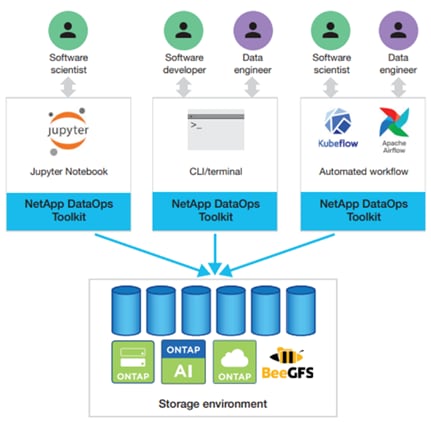
The NetApp DataOps Toolkit is a Python library that makes it easy for developers, data scientists, and data engineers to perform numerous data management tasks. These tasks include provisioning a new data volume or development workspace, cloning a data volume or development workspace almost instantaneously, and creating a NetApp Snapshot copy of a data volume or development workspace for traceability and baselining. This Python library can function as either a command-line utility or a library of functions that can be imported into any Python program or Jupyter Notebook.
The DataOps Toolkit supports Linux and macOS hosts. The toolkit must be used in conjunction with a NetApp data storage system or service. It simplifies various data management tasks that are executed by the data storage system or service. To facilitate this simplification, the toolkit communicates with the data storage system or service through an API.
The NetApp DataOps Toolkit for Kubernetes abstracts storage resources and Kubernetes workloads up to the data-science workspace level. These capabilities are packaged in a simple, easy-to-use interface that is designed for data scientists and data engineers. Using the familiar form of a Python program, the Toolkit enables data scientists and engineers to provision and destroy JupyterLab workspaces in just seconds. These workspaces can contain terabytes, or even petabytes, of storage capacity, enabling data scientists to store all their training datasets directly in their project workspaces. Gone are the days of separately managing workspaces and data volumes.
AI/ML Use Cases - DataOps for Data Scientist
With the NetApp DataOps Toolkit, a data scientist can almost instantaneously create a space-efficient data volume that’s an exact copy of an existing volume regardless of the size of the dataset. Data scientists can quickly create clones of datasets that they can reformat, normalize, and manipulate, while preserving the original “gold-source” dataset. Under the hood, these operations use highly efficient and battle-tested NetApp FlexClone feature, but they can be performed by a data scientist without storage expertise. What used to take days or weeks (and the assistance of a storage administrator) now takes seconds.
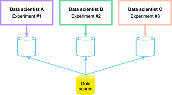
Data scientists can also save a space-efficient, read-only copy of an existing data volume. Based on the famed NetApp Snapshot technology, this functionality can be used to version datasets and implement dataset-to-model traceability. In regulated industries, traceability is a baseline requirement, and implementing it is extremely complicated with most other tools. With the NetApp DataOps Toolkit, it’s quick and easy.
More operations and capabilities are available and documented here: https://github.com/NetApp/netapp-data-science-toolkit
This chapter contains the following:
The FlexPod AI with Cisco UCS and NetApp storage meets the following general design requirements:
● Resilient design across all layers of the infrastructure with no single point of failure.
● Scalable design with the flexibility to add compute capacity, storage, or network bandwidth as needed.
● Modular design that can be replicated to expand and grow as the needs of the business grow.
● Flexible design that can support different models of various components with ease.
● Simplified design with ability to integrate and automate with external automation tools.
● Cloud-enabled design which can be configured, managed, and orchestrated from the cloud using GUI or APIs.
To deliver a solution which meets all these design requirements, various solution components are connected and configured as explained in the following sections.
Table 1 lists the required physical components and hardware for FlexPod AI.
Table 1. FlexPod AI Hardware Components
| Component |
Hardware |
| Servers |
Eight (8) Cisco UCS C240 M7 rack server |
| Storage |
NetApp AFF A400 |
| Network |
Two (2) Cisco Nexus 93600CD-GX |
Table 2. Cisco UCS C240 M7 Hardware Components
| Component |
Hardware |
| Processor |
Two (2) 4th Gen Intel® Xeon® Scalable Processor 6454S 32C/2.2GHz/270W |
| Memory |
Sixteen (16) 64GB DDR5-4800 RDIMM |
| NIC (Network Interface Card) |
Mellanox ConnectX-6 DX 2 x 100Gb Ethernet |
| GPU (Graphics Processing Unit) |
NVIDIA Tesla A100-80GB GPU |
Table 3. NetApp AFF A400 Components
| Component |
Hardware |
| AFF Flash Array |
NetApp All Flash AFF A400 Storage Array (4RU) |
| Capacity |
27.8TB (12 x 3.49TB NVMe SSD Drives) |
| Connectivity |
4 x 100Gb/s (2 x 100Gb per controller) Data Rate: 100 Gb/s Ethernet, PCI Express Gen3: SERDES @ 8.0GT/s, 16 lanes) (MCX516A-CCAT) 1 Gb/s redundant Ethernet (Management port) |
Software Components
Table 4 lists the software components and the versions required for FlexPod AI as tested and validated in this document.
Table 4. FlexPod AI Software Components
| Component |
Software version |
| Cisco Intersight |
SaaS platform |
| Cisco UCS Server Firmware |
4.3(2.230207) |
| Host OS |
Ubuntu 22.04 LTS |
| Mellanox ConnectX-6 NIC |
22.36.1010 |
| MLNX OFED 5.8-1.1.2.1 |
|
| NVIDIA Tesla A100-80GB GPU |
NVIDIA CUDA 12.2.2 |
| NVIDIA Driver 535.104.05 |
|
| NetApp AFF A400 |
ONTAP 9.12.1 |
| Cisco Nexus 93600CD-GX |
NX-OS 10.3.3 |
Note: See the Bill of Materials section for a complete list and corresponding PID.
Required VLANs
Table 5 lists various VLANs configured for setting up the FlexPod environment including their specific usage.
Table 5. FlexPod AI – VLAN Usage
| VLAN ID |
Name |
Usage |
| 2 |
Native-VLAN |
Use VLAN 2 as Native VLAN instead of default VLAN (1) |
| 248 |
OOB-MGMT-VLAN |
Management VLAN to access and manage the servers |
| 110 |
AI-ML-NFS_1 |
NFS VLAN to access AI/ML NFS volume hosting HPC data |
| 160 |
AI-ML-NFS_2 |
NFS VLAN to access AI/ML NFS volume hosting HPC data |
Some of the key highlights of VLAN usage are as follows:
● Bare-metal servers are managed using same management in-band VLAN: IB-MGMT-VLAN (248).
● Utilizing dedicated NFS VLANs for HPC and AI; hosts provide path selection flexibility and the ability to configure specific QoS policies. You are encouraged to use separate, dedicated VLANs for NFS traffic.
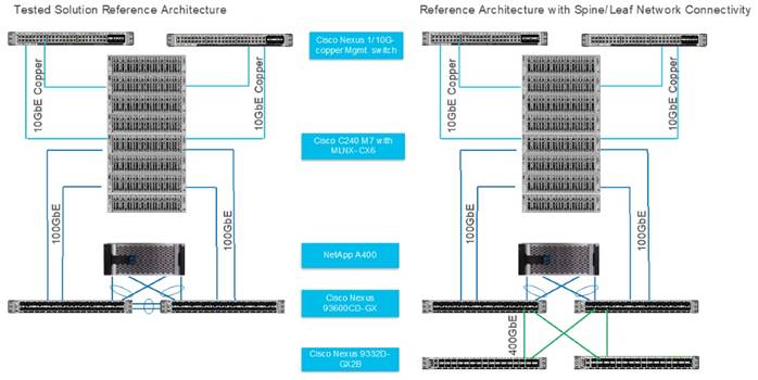
For this solution, we tested left side configuration as shown in Figure 8 with Cisco UCS C-Series Rack Server and NetApp AFF A400 storage array connected to Cisco Nexus 93600CD-GX leaf switch with layer 2 configuration for a single rack testing. For large cluster spanning across multiple racks and Spine/Leaf networking best practices, please refer to Cisco Data Center Networking Blueprint for AI/ML Applications.
Note: This solution is tested with Cisco VIC 15428 ( 4x 10/25/50G mLOM C-Series) for 10GbE connection with ToR switch and utilized for separate OS management from data traffic on Mellanox ConnectX6-DX Ethernet NIC.
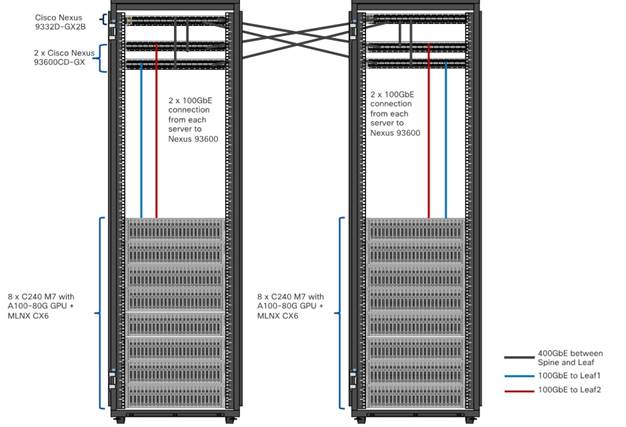
The single rack topology of the FlexPod AI architecture highlighted in this CVD can be easily expanded to a larger size cluster connecting hundreds of servers with Spine-Leaf network design where congestion management enabled on leaf layer and spine later with PFC and ECN as shown in Figure 9.
The information in this section is provided as a reference for cabling the physical equipment in a FlexPod environment. To simplify cabling requirements, a cabling diagram was used.
The cabling diagram in this section contains the details for the prescribed and supported configuration of the NetApp AFF 400 running NetApp ONTAP 9.12.1.
| Tech tip |
| For any modifications of this prescribed architecture, consult the NetApp Interoperability Matrix Tool (IMT). This document assumes that out-of-band management ports are plugged into an existing management infrastructure at the deployment site. These interfaces will be used in various configuration steps. Be sure to use the cabling directions in this section as a guide. The NetApp storage controller and disk shelves should be connected according to best practices for the specific storage controller and disk shelves. For disk shelf cabling, refer to NetApp Support. |
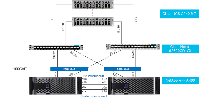
Figure 10 details the cable connections used in the validation lab for the FlexPod topology based on the Cisco UCS C240 M7 stand-alone server managed via Intersight and NetApp AFF A400 storage array. Two 100Gb uplinks connect as port-channels from each Cisco UCS Nexus 93600CD-GX switches to the NetApp AFF controllers. Additional 1Gb management connections will be needed for an out-of-band network switch that sits apart from the FlexPod infrastructure. Each Cisco UCS C240 M7 rack server and Cisco Nexus switch is connected to the out-of-band network switch, and each AFF controller has a connection to the out-of-band network switch. Layer 3 network connectivity is required between the Out-of-Band (OOB) and In-Band (IB) Management Subnets.
This chapter contains the following:
● Network Switch Configuration
● NetApp ONTAP Storage Configuration
● Cisco Intersight Configuration
● Mellanox ConnectX-6 NIC Best Practice
● NVIDIA GPU Configuration for HPC Workload
Designing a network infrastructure for an HPC and AI cluster requires careful consideration to ensure efficient data transfer, low latency, and scalability. The network configuration tuned to match the specific requirements of your HPC and AI workloads via implementation of QoS (Quality of Service) to ensure efficient utilization and monitoring of the network resources available.
Please refer to Cisco Data Center Networking Blueprint for AI/ML Applications for more detailed documentation on best practices for lossless network design and configuration required for HPC and AI workload.
This section provides a detailed procedure for configuring the Cisco Nexus 93600CD-GX switches for use in a FlexPod AI/ML environment. The Cisco Nexus 93600CD-GX will be used for LAN switching in this solution. This configuration allows deployment of Cisco AI/ML platforms in bare-metal server configuration.
| Tech tip |
| The following procedures describe how to configure the Cisco Nexus switches for use in a base FlexPod environment. This procedure assumes the use of Cisco Nexus 9000 NX-OS 10.3.3F. The following procedure includes the setup of NTP distribution on both the mgmt0 port and the in-band management VLAN. The interface-vlan feature and ntp commands are used to set this up. This procedure also assumes that the default VRF is used to route the in-band management VLAN. This procedure sets up and uplink virtual port channel (vPC) with the IB-MGMT and OOB-MGMT VLANs allowed. This validation assumes that both switches have been reset to factory defaults by using the “write erase” command followed by the “reload” command. |
Physical Connectivity
Follow the physical connectivity guidelines for FlexPod as explained in the Physical Topology section.
Initial Configuration
The following procedures describe this basic configuration of the Cisco Nexus switches for use in the FlexPod environment. This procedure assumes the use of Cisco Nexus 9000 10.2(5)M, the Cisco suggested Nexus switch release at the time of this validation.
Procedure 1. Set Up Initial Configuration from a serial console
Step 1. Set up the initial configuration for the Cisco Nexus 93600CD-GX switch.
Procedure 2. Configure Global Settings on both Cisco Nexus Switches
| Tech tip |
| Remote Direct Memory Access (RDMA) over Converged Ethernet (RoCE); for RoCEv2 transport, the network must provide high throughput and low latency while avoiding traffic drops in situations where congestion occurs. The following procedures describe how to configure the Cisco Nexus switches global configuration highlighting for RoCE V2 and QoS, no-drop shown. Please refer Appendix for full configuration. |
Step 1. Login as admin user into the Cisco Nexus switch A and run the following commands to set the global configuration on switch:
configure terminal
policy-map type network-qos qos_network
class type network-qos c-8q-nq3
mtu 9216
pause pfc-cos 3
class type network-qos c-8q-nq-default
mtu 9216
class-map type qos match-any CNP
match dscp 48
class-map type qos match-all ROCEv2
match dscp 24,26
policy-map type qos QOS_MARKING
class ROCEv2
set qos-group 3
class CNP
set qos-group 7
class class-default
set qos-group 0
policy-map type queuing QOS_EGRESS_PORT
class type queuing c-out-8q-q6
bandwidth remaining percent 0
class type queuing c-out-8q-q5
bandwidth remaining percent 0
class type queuing c-out-8q-q4
bandwidth remaining percent 0
class type queuing c-out-8q-q3
bandwidth remaining percent 50
random-detect minimum-threshold 150 kbytes maximum-threshold 3000 kbytes drop-probability 7 weight 0 ecn
class type queuing c-out-8q-q2
bandwidth remaining percent 0
class type queuing c-out-8q-q1
bandwidth remaining percent 0
class type queuing c-out-8q-q-default
bandwidth remaining percent 50
class type queuing c-out-8q-q7
priority level 1
system qos
service-policy type network-qos qos_network
service-policy type queuing output QOS_EGRESS_PORT
copy running-config startup-config
Step 2. Login as admin user into Cisco Nexus Switch B; repeat steps 1 and 2 above to set up the global configuration.
| Tech tip |
| Make sure to run copy run start to save the configuration on each switch after the configuration is completed. |
NetApp ONTAP Storage Configuration
NetApp AFF A-Series Storage System
NetApp AFF A-Series is a family of all-flash storage systems by NetApp. The systems are designed to provide high-performance, low-latency and highly available storage solution suitable for a wide range of enterprise applications such as AI/ML, databases, and virtualization.
NetApp storage systems support a wide variety of disk shelves and disk drives. The complete list of disk shelves that are supported by the AFF A400 is available at the NetApp Support site.
Follow the physical installation procedures for the controllers found here: https://docs.netapp.com/us-en/ontap-systems/index.html.
When using SAS disk shelves with NetApp storage controllers, refer to: https://docs.netapp.com/us-en/ontap-systems/sas3/install-new-system.html for proper cabling guidelines.
When using NVMe drive shelves with NetApp storage controllers, refer to: https://docs.netapp.com/us-en/ontap-systems/ns224/hot-add-shelf.html for installation and servicing guidelines.
For more information about the setup and configuration of the NetApp AFF A-Series storage system setup and deployment FlexPod solution, go to:
https://www.netapp.com/data-storage/flexpod/validated-designs/
This section contains the following:
| Tech tip |
| Please visit Cisco UCS C240 M7 Server Installation and Service Guide: https://www.cisco.com/c/en/us/td/docs/unified_computing/ucs/c/hw/C240M7/install/b-cisco-c240-m7-install/m-installing.html Please visit GPU card installation on C240 M7: https://www.cisco.com/c/en/us/td/docs/unified_computing/ucs/c/hw/C240M7/install/b-cisco-c240-m7-install/m-gpu-install.html Please visit Cisco UCS C-Series Integrated Management Controller GUI Configuration Guide: https://www.cisco.com/c/en/us/td/docs/unified_computing/ucs/c/sw/gui/config/guide/4_3/b_cisco_ucs_c-series_gui_configuration_guide_43.html |
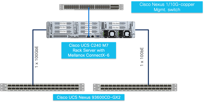
To manage Cisco UCS C240 M7 Rack Server connected to Cisco Nexus switch directly; connect and configure Cisco Integrated Management Controller connect CIMC port to ToR (top of rack) switch as shown in Figure 11.
| Tech tip |
| The Cisco IMC management service is used only when the server is operating in Standalone Mode. If your C-Series server is integrated into a UCS system, you must manage it using a Cisco UCS Fabric Interconnect running in either CSM or IMM. For information about using UCS Manager, see the configuration guides listed in the Cisco UCS B-Series Servers Documentation Roadmap at http://www.cisco.com/go/unifiedcomputing/b-series-doc. |
Cisco Intersight Configuration
This section contains the following:
● Template and Profile Configuration
● Install Operating System using Cisco Intersight
Cisco Intersight Infrastructure Service allows policy managed infrastructure configuration for ease of management, monitoring and Remediate issues and stay ahead with proactive awareness of Cisco UCS Infrastructure.
| Tech tip |
| Please visit Intersight Help Center for more details: https://us-east-1.intersight.com/help/saas/home |
This section highlights initial configuration required to claim a target in a new or existing Cisco Intersight account. Based on the requirement and intended configuration for Cisco Intersight managed Infrastructure either create new pools, policies, template, and profiles or leverage existing configuration for faster deployment. Github repositories for automated FlexPod deployment and configuration can be found here: https://github.com/orgs/ucs-compute-solutions/repositories
This procedure details how to claim a Cisco UCS standalone server using Cisco Intersight.
Step 1. Log into CIMC web UI https://<cimc_mgmt_ip> and enter your username and password.
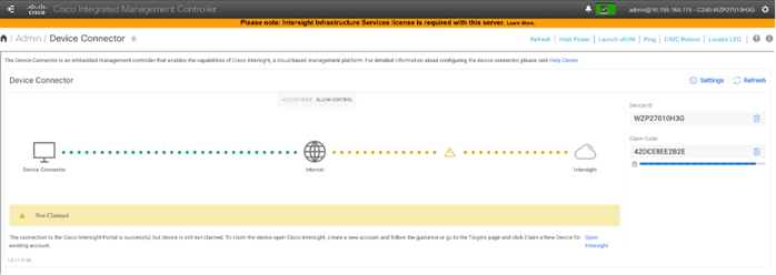
Step 2. Go to Admin > Device Connector.
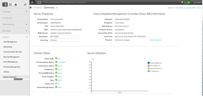
Note: This is the first step. In general, processes should have multiple procedures, and procedures should have multiple steps.
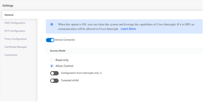
Step 3. Update settings input as appropriate and click Save.
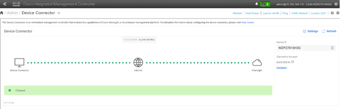
Step 4. Copy Device ID and Claim code to be entered while claiming a target in Cisco Intersight.
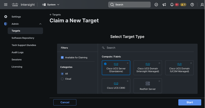
Step 5. Log into Cisco Intersight; go to System > Targets. Click Claim a new Target.
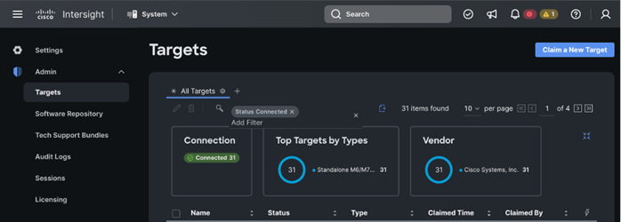
Step 6. Select Cisco UCS Server (standalone) in Compute/Fabric section. Click Start.
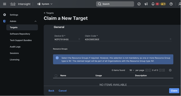
Step 7. Enter Device ID and Claim Code copied from Cisco CIMC for the standalone server to claim in the Cisco Intersight.
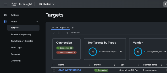
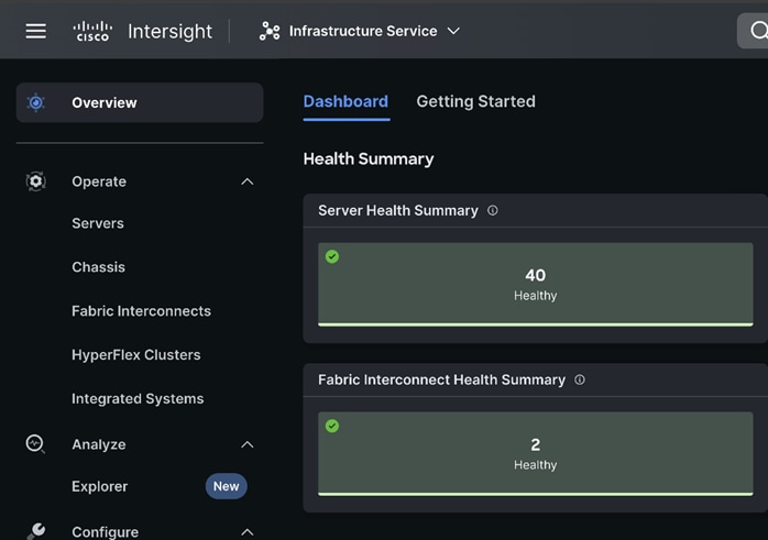
Cisco CIMC and Cisco Intersight WebUI reporting Cisco UCS Rack Server claimed and connected is shown below:
| Tech tip |
| For more information on licensing requirements for Infrastructure Services, see Infrastructure Services License. |
You can either create the required pools and policies to attach to a server profile or create them as progressing through the server profile/template creation.
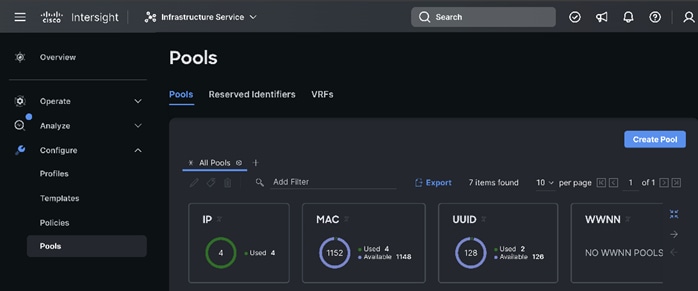
Step 1. Log into Cisco Intersight. Go to Infrastructure Service.
Step 2. Select Pools and click Create Pool.
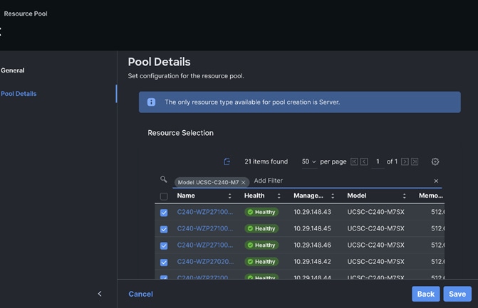
Step 3. Select Resources. Click Start. Enter a name for the new Resource Pool. Select the Target Platform to add in the resource pool. Select by filtering the set of nodes to be part of the resource pool. For example, UCSC-C240-M7 as shown below:
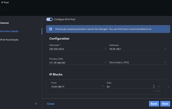
Step 4. Create the IP Pool for KVM access as shown below:
This section provides the screenshots where input is required to complete the policy creation. The process remains the same, such as selection of organization, entering name for the policy, tags, and description.
Step 1. Go to Policies. Select type of policy to create.
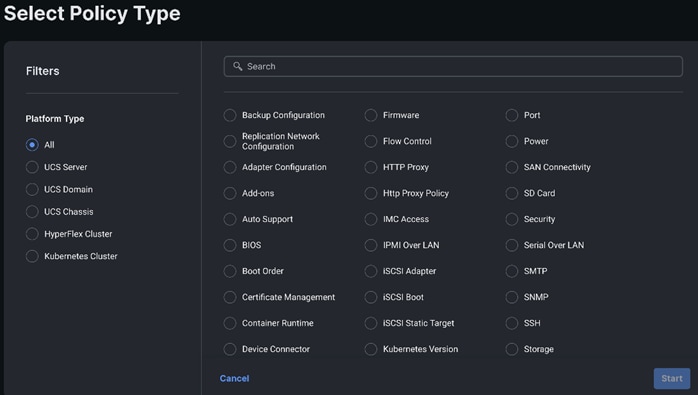
Step 2. Select BIOS and click Start.
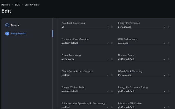
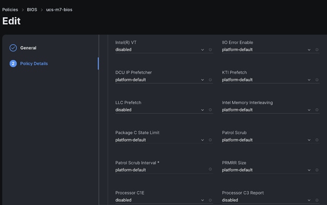
Step 3. We kept all settings as platform-default, except for the following parameters changes in the BIOS policy:
● LLC dead line – Disabled
● Intel Virtualization Technology – Disabled
● LLC prefetch – Disabled
● Workload configuration – Balanced
| Selection of BIOS parameters determines the cluster optimization for performance or power saving or balanced of performance and power savings goal. Please review Performance Tuning Best Practices Guide for Cisco UCS M7 Platforms: https://www.cisco.com/c/en/us/products/collateral/servers-unified-computing/ucs-b-series-blade-servers/ucs-m7-platforms-wp.html |
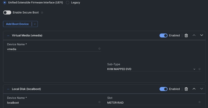
Step 4. Create Boot order policy. Select UCS Standalone Server. Select Boot Mode. Click Add Boot Device. Select LocalDisk from the drop-down list for “Add Boot Device.” For the device name and Slot enter “MSTOR-RAID.”
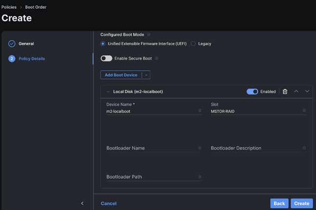
Note: Additional boot devices can be added as per the requirement.

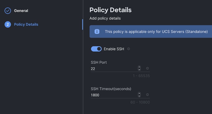
Step 5. Create the SSH policy.
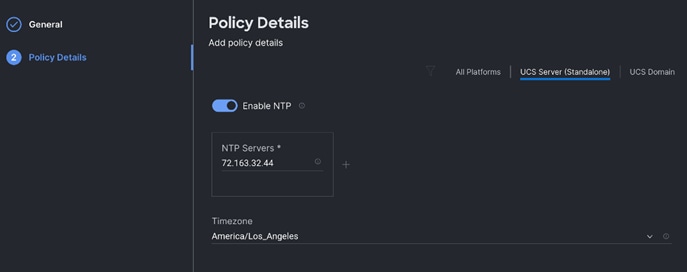
Step 6. Create the NTP policy.
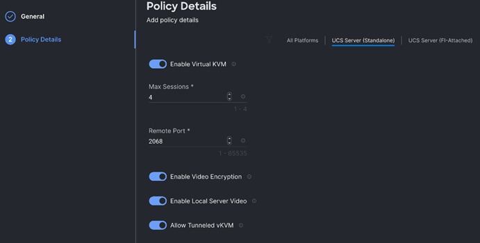
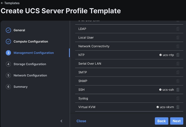
Step 7. Create the Virtual KVM policy.
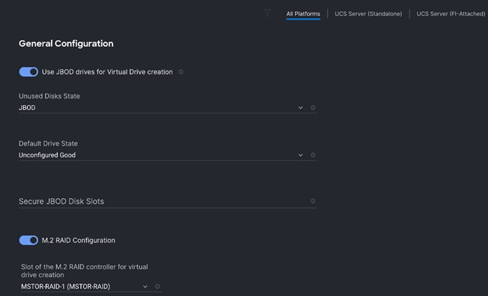
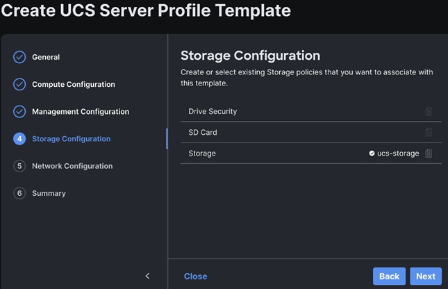
Step 8. Create the Storage policy to create RAID 1 on two M.2 SATA SSD with boot optimized RAID controller. Select M.2 RAID configuration. From the drop-down list select MSTOR-RAID-1(MSTOR-RAID).
Template and Profile Configuration
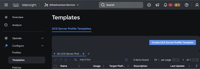
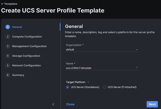
Step 1. In Cisco UCS Infrastructure Services page, go to Templates. Click Create UCS Server Profile Template.
Step 2. Enter a name for the Server Profile Template and select the Target Platform.
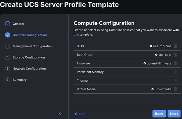
Step 3. Select policies or create new to associate with the server profile template.
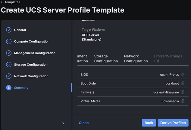
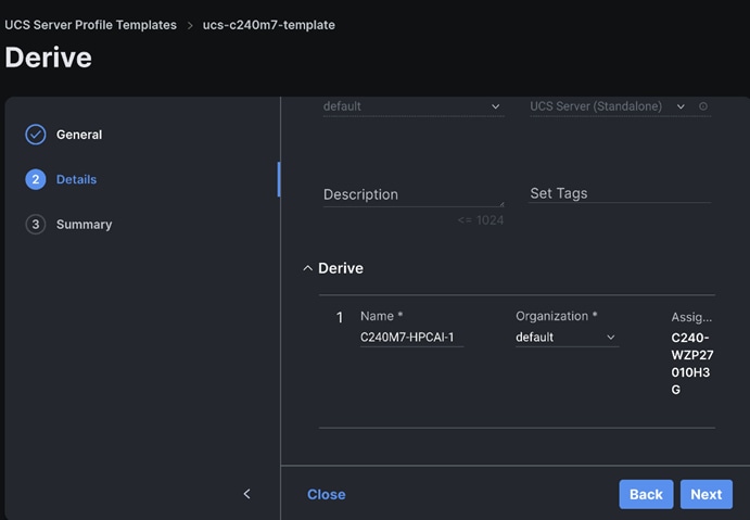
Step 4. Review and click Derive Profiles.
Step 5. Select the Server Assignment.
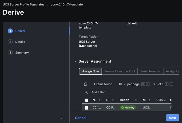
Step 6. Edit the name for the server profile(s) to be derived from the template.
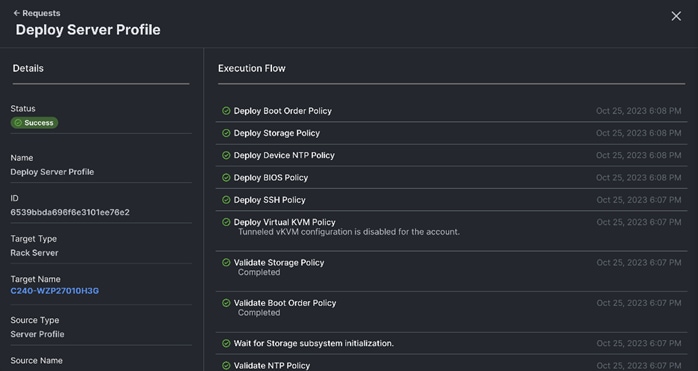
Step 7. Click Deploy Server Profile. Monitor the Server profile deployment task.
Install Operating System using Cisco Intersight
Prerequisites
Create the NFS or HTTPS file share location to be consumed for the Operating System, Cisco UCS SCU, and the Cisco UCS HUU repository.
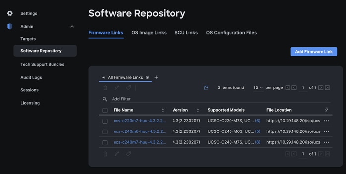
Step 1. Download ISO and copy the path location to be added in Software Repository tab.
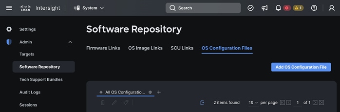
Step 2. Log into Cisco Intersight. Go to System > Software Repository.
Step 3. Go to OS Image Links and click Add OS Image Link.
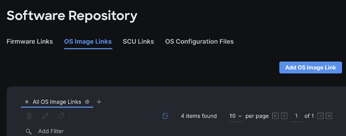
Step 4. Select NFS or CIFS or HTTP/s, enter file location, username, and password.
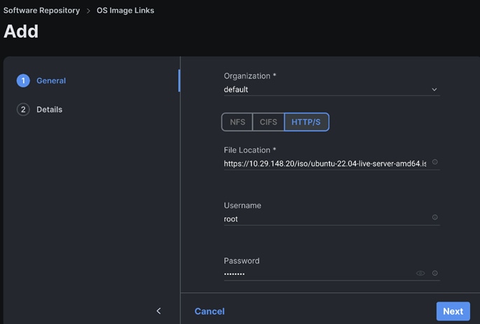
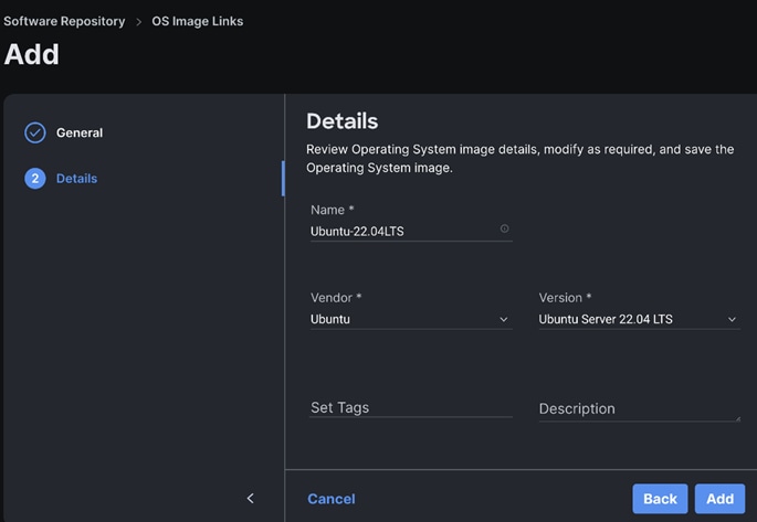
Step 5. Enter the Details.
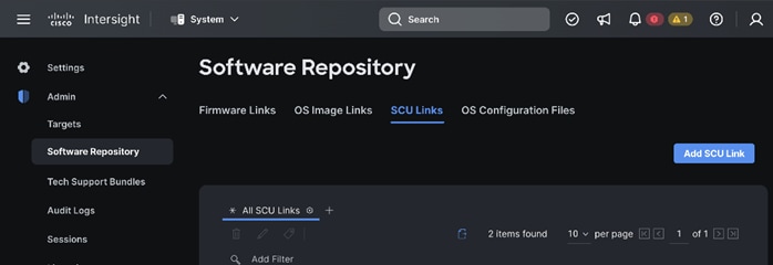
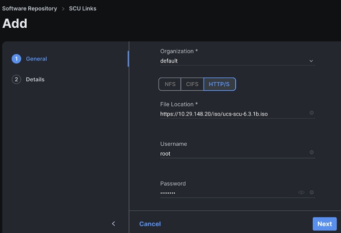
Step 6. Go to SCU Links page System > Software Repository. Click Add SCU Link.
Step 7. Enter the File Location, Username and Password. Click Next.
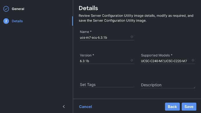
Step 8. Review the Server Configuration Utility.
Step 9. Go to the OS Configuration Files tab. Add the OS configuration file for Operating System Installation (optional).
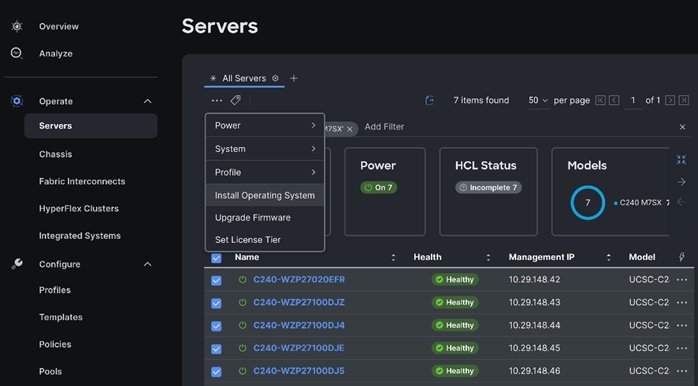
Step 10. Go to Infrastructure Service > Servers. Select system(s) to perform Install Operating System. Right-click on the ellipses and select Install Operating System.
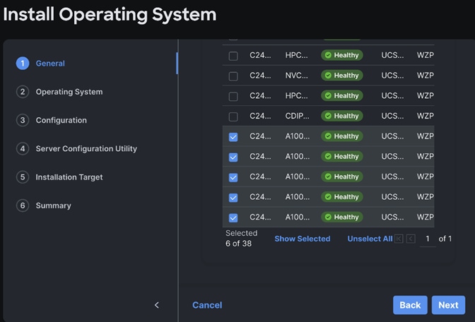
Step 11. The selected system(s) are already part of the Operating System Install task. Edit the list if required. Click Next.
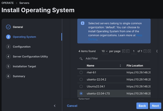
Step 12. Select the OS Image Link for the intended operating system to be installed.
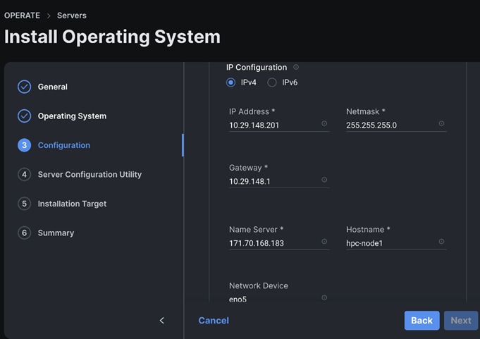
Step 13. Enter the configuration details for the Operating System to be installed as shown in the screenshot below. Repeat these steps for all system(s).
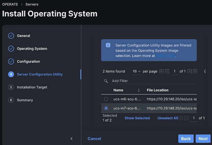
Step 14. Select the Server Configuration Utility Image.
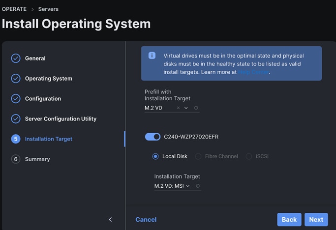
Step 15. Select the Installation Target. We selected M.2 VD from the drop-down list.
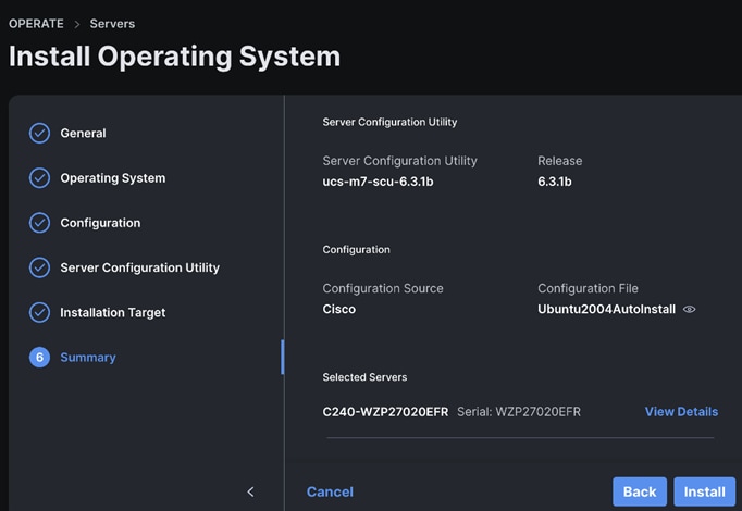
Step 16. Review the Operating System Installation Summary. Click Install.
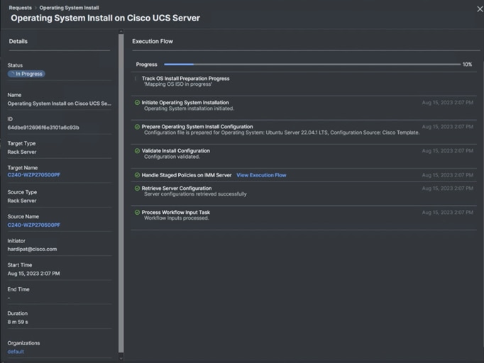
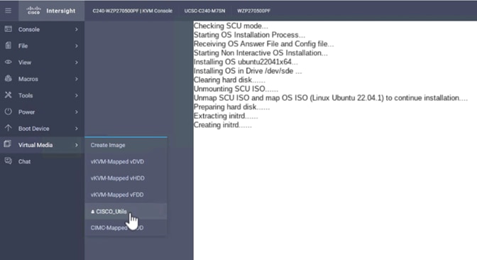
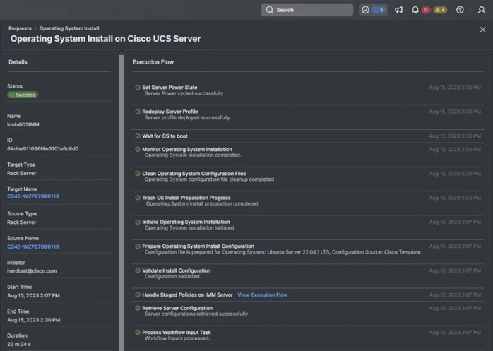
Step 17. Review the Installation workflow in execution.
This section contains the post-OS configuration steps:
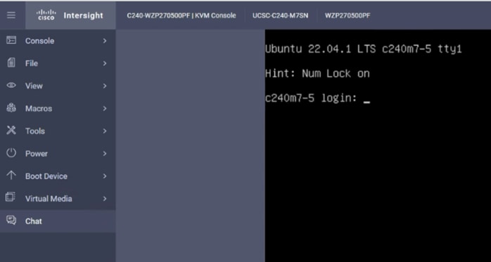
Step 1. Log into the Ubuntu OS management IP address configured during the Cisco Intersight based Install Operating System using the SSH client. Enter the username “ubuntu” and the password entered while setting up the custom configuration:
$ ssh ubuntu@10.29.148.171
Edit /etc/hosts
$ cat /etc/hosts
127.0.0.1 localhost
127.0.1.1 hpc-node1
10.29.148.171 hpc-node1
10.29.148.172 hpc-node2
10.29.148.173 hpc-node3
10.29.148.174 hpc-node4
10.29.148.175 hpc-node5
10.29.148.176 hpc-node6
10.29.148.177 hpc-node7
10.29.148.178 hpc-node8
# The following lines are desirable for IPv6 capable hosts
::1 ip6-localhost ip6-loopback
fe00::0 ip6-localnet
ff00::0 ip6-mcastprefix
ff02::1 ip6-allnodes
ff02::2 ip6-allrouters
Note: If it’s not already installed, the following steps require openssh-server to be installed using "sudo apt install -y openssh-server"
Step 2. Add a new user:
$ adduser <username>
Adding user `<username>' ...
Adding new group `<username>' (1001) ...
Adding new user `<username>' (1001) with group `<username> ...
Creating home directory `/home/<username>' ...
Copying files from `/etc/skel' ...
New password: <Password!>
Retype new password: <Password!>
passwd: password updated successfully
Changing the user information for <username>
Enter the new value, or press ENTER for the default
Full Name []: FirstName LastName
Room Number []:
Work Phone []:
Home Phone []:
Other []:
Is the information correct? [Y/n] Y
$ usermod -aG sudo <username>
$ su - <username>
To run a command as administrator (user "root"), use "sudo <command>".
See "man sudo_root" for details.
Step 3. Setup a password-less login:
This process needs to be completed on each node so that all nodes can be accessed without password for HPC cluster test as documented in following section.
$ ssh-keygen -N '' -f ~/.ssh/id_rsa
$ for i in {1..8}; do echo "copying hpc-node$i"; ssh-copy-id -i /home/ubuntu/.ssh/id_rsa.pub ubuntu@HPC-Node$i; done;
Step 1. Install ansible:
$ sudo apt update
$ sudo apt install software-properties-common
$ sudo add-apt-repository --update ppa:ansible/ansible --> Press Enter when prompted
$ sudo apt update
$ sudo apt install -y ansible-core ansible
$ ansible --version
ansible [core 2.15.4]
config file = /etc/ansible/ansible.cfg
configured module search path = ['/home/hardipat/.ansible/plugins/modules', '/usr/share/ansible/plugins/modules']
ansible python module location = /usr/lib/python3/dist-packages/ansible
ansible collection location = /home/hardipat/.ansible/collections:/usr/share/ansible/collections
executable location = /usr/bin/ansible
python version = 3.10.12 (main, Jun 11 2023, 05:26:28) [GCC 11.4.0] (/usr/bin/python3)
jinja version = 3.0.3
libyaml = True
Step 2. Edit /etc/ansible/hosts:
$ sudo vi /etc/ansible/hosts
[hpcnodes]
hpc-node1 ansible_host=10.29.148.171
hpc-node2 ansible_host=10.29.148.172
hpc-node3 ansible_host=10.29.148.173
hpc-node4 ansible_host=10.29.148.174
hpc-node5 ansible_host=10.29.148.175
hpc-node6 ansible_host=10.29.148.176
hpc-node7 ansible_host=10.29.148.177
hpc-node8 ansible_host=10.29.148.178
[all:vars]
ansible_python_interpreter=/usr/bin/python3
Step 3. Test ansible:
$ ansible-inventory --list -y
all:
children:
admin:
hosts:
10.29.148.22:
ansible_python_interpreter: /usr/bin/python3
hpcnodes:
hosts:
hpc-node1:
ansible_host: 10.29.148.171
ansible_python_interpreter: /usr/bin/python3
hpc-node2:
ansible_host: 10.29.148.172
ansible_python_interpreter: /usr/bin/python3
hpc-node3:
ansible_host: 10.29.148.173
ansible_python_interpreter: /usr/bin/python3
hpc-node4:
ansible_host: 10.29.148.174
ansible_python_interpreter: /usr/bin/python3
hpc-node5:
ansible_host: 10.29.148.175
ansible_python_interpreter: /usr/bin/python3
hpc-node6:
ansible_host: 10.29.148.176
ansible_python_interpreter: /usr/bin/python3
hpc-node7:
ansible_host: 10.29.148.177
ansible_python_interpreter: /usr/bin/python3
hpc-node8:
ansible_host: 10.29.148.178
ansible_python_interpreter: /usr/bin/python3
$ ansible all -m command -a "uname -r"
hpc-node2 | CHANGED | rc=0 >>
5.15.0-84-generic
hpc-node4 | CHANGED | rc=0 >>
5.15.0-84-generic
| Tech tip |
| To enable root login; edit "/etc/ssh/sshd_config" as --> PermitRootLogin yes $ sudo passwd root [sudo] password for ubuntu: New password: Retype new password: passwd: password updated successfully |
Step 4. Setup NTP:
$ ansible all -m command -a "sudo timedatectl set-timezone America/Los_Angeles"
$ # ansible all -m command -a "sudo timedatectl set-ntp false"
$ ansible all -m command -a "sudo timedatectl set-time hh:mm"
$ ansible all -m command -a "sudo timedatectl set-time true"
$ ansible all -m command -a "sudo apt install ntp -y"
Step 5. Edit /etc/ntp.conf and copy on all nodes:
$ vi /etc/ntp.conf
pool 72.163.32.44 iburst
$ ansible all -m copy -a "src=/etc/ntp.conf dest=/etc/ntp.conf"
Step 6. Start NTP service:
$ ansible all -m command -a "sudo systemctl start ntp"
$ ansible all -m command -a "sudo systemctl enable ntp"
Step 7. Install required packages:
$ ansible all -m command -a "sudo apt-get update"
$ ansible all -m command -a "sudo apt-get install build-essential -y"
$ ansible all -m command -a "sudo apt install -y pip sshpass unzip -y"
$ ansible all -m command -a "sudo apt install environment-modules -y"
$ ansible all -m command -a "sudo apt install dkms -y"
$ ansible all -m command -a “sudo apt install make cmake -y”
Step 8. Update Grub by editing /etc/default/grub:
$ ansible all -m shell -a "sed -i 's/GRUB__CMDLINE_LINUX_DEFAULT="[^"]*/& iommu=pt numa_balancing=disable pci=realloc=off processor.max_cstate=0/' /etc/default/grub"
$ ansible all -m shell -a "update-grub"
Step 9. Disable Nouveau by running following commands:
$ ansible all -m shell -a "bash -c "echo blacklist nouveau > /etc/modprobe.d/blacklist-nvidia-nouveau.conf""
$ ansible all -m shell -a "bash -c "echo options nouveau modeset=0 >> /etc/modprobe.d/blacklist-nvidia-nouveau.conf""
$ ansible all -m shell -a "update-initramfs -u"
| Tech tip |
| The previous steps require a reboot: $ ansible all -m command -a "sudo reboot" |
Step 10. Disable firewall (or edit firewall configuration to allow NTP, NFS, other network traffic as appropriate):
$ ansible all -m shell -a "sudo UFW disable”
Step 11. Disable SELinux:
$ sudo vi /etc/selinux/config
SELINUX=disabled
$ ansible all -m copy -a “src=/etc/selinux/config dest=/etc/selinux/config”
Mellanox ConnectX-6 NIC Best Practice
This section highlights the steps required for the Mellanox ConnectX6-DX ehternet network interface card configuration for Ubuntu OS:
● Mellanox OFED Driver Installation
● Configure Network Adapter Ports for Ubuntu
● Mellanox ConnectX-6 NIC best practice for PFC, ECN and DSCP
● Connect NetApp Storage provided FlexVolume(s) using NFS Mount
Mellanox OFED Driver Installation
Step 1. Install Mellanox OFED for Mellanox ConnectX-6 DX Ethernet Network Interface Card. Download Mellanox OFED from the following URL: https://www.mellanox.com/page/mlnx_ofed_eula?mtag=linux_sw_drivers&mrequest=downloads&mtype=ofed&mver=MLNX_OFED-5.8-1.1.2.1&mname=MLNX_OFED_LINUX-5.8-1.1.2.1-ubuntu22.04-x86_64.tgz
Step 2. Accept EUA to download Mellanox OFED Software:
$ scp MLNX_OFED_LINUX-5.8-1.1.2.1-ubuntu22.04-x86_64.tgz ubuntu@10.29.148.171:/home/ubuntu/
$ ansible all -m copy -a “src=/home/ubuntu/ MLNX_OFED_LINUX-5.8-1.1.2.1-ubuntu22.04-x86_64.tgz dest==/home/ubuntu/ MLNX_OFED_LINUX-5.8-1.1.2.1-ubuntu22.04-x86_64.tgz”
$ ansible all -m shell -a “tar xvf /home/ubuntu/ MLNX_OFED_LINUX-5.8-1.1.2.1-ubuntu22.04-x86_64.tgz”
ansible all -m command -a "sudo /home/ubuntu/MLNX_OFED_LINUX-5.8-1.1.2.1-ubuntu22.04-x86_64/mlnxofedinstall --without-fw-update --force"
$ ansible all -m command -a "sudo /etc/init.d/openibd restart"
$ ansible all -m command -a "sudo reboot"
$ ansible all -m command -a "ofed_info -s"
hpc-node1 | CHANGED | rc=0 >>
MLNX_OFED_LINUX-5.8-1.1.2.1:
hpc-node2 | CHANGED | rc=0 >>
MLNX_OFED_LINUX-5.8-1.1.2.1:
Step 3. Start MST:
$ sudo mst start
$ sudo mst status -v
MST modules:
------------
MST PCI module is not loaded
MST PCI configuration module loaded
PCI devices:
------------
DEVICE_TYPE MST PCI RDMA NET NUMA
ConnectX6DX(rev:0) /dev/mst/mt4125_pciconf0.1 27:00.1 mlx5_1 net-ens2f1np1 0
ConnectX6DX(rev:0) /dev/mst/mt4125_pciconf0 27:00.0 mlx5_0 net-ens2f0np0 0
| Tech tip |
| GPU Direct RDMA and GPU Direct Storage link: https://docs.nvidia.com/datacenter/cloud-native/gpu-operator/23.6.1/gpu-operator-rdma.html |
Configure Network Adapter Ports for Ubuntu
Step 1. Run the following commands:
$ ansible all -m command -a "sudo apt update"
$ ansible all -m command -a "sudo apt install lldpad -y"
$ ansible all -m command -a "sudo modprobe 8021q"
$ ansible all -m command -a "sudo su -c 'echo "8021q" >> /etc/modules'"
$ ansible all -m command -a "sudo apt install vlan -y"
Step 2. Edit /etc/netplan/00-installer-config.yaml to configure Mellanox NIC port with desired network configuration. For example, the following configuration is for Mellanox port1 (ens2f0np0) and port2 (ens2f1np1) connected to Cisco Nexus Switch A and B in Spine – Leaf architecture for data traffic.
$ cat /etc/netplan/00-installer-config.yaml
# This is the network config written by 'subiquity'
network:
ethernets:
eno5:
addresses:
- 10.29.148.171/24
dhcp4: false
nameservers:
addresses:
- 171.70.168.183
search: []
routes:
- to: default
via: 10.29.148.1
ens2f0np0:
dhcp4: false
ens2f1np1:
dhcp4: false
vlans:
ens2f0np0.110:
id: 110
link: ens2f0np0
mtu: 9000
addresses:
- 192.168.110.171/24
routes:
- to: 192.168.110.0/24
via: 192.168.110.1
metric: 100
ens2f1np1.160:
id: 160
link: ens2f1np1
mtu: 9000
addresses:
- 192.168.160.171/24
routes:
- to: 192.168.160.0/24
via: 192.168.160.1
metric: 100
version: 2
Mellanox ConnectX-6 NIC Best Practice for PFC, ECN and DSCP
Step 1. Enable ECN (Explicit congestion notification) priority 3:
$ ansible all -m command -a "sudo echo 1 > /sys/class/net/ens2f0np0/ecn/roce_rp/enable/3"
$ ansible all -m command -a "sudo echo 1 > /sys/class/net/ens2f1np1/ecn/roce_rp/enable/3"
$ ansible all -m command -a "sudo echo 1 > /sys/class/net/ens2f0np0/ecn/roce_np/enable/3"
$ ansible all -m command -a "sudo echo 1 > /sys/class/net/ens2f1np1/ecn/roce_np/enable/3"
Step 2. Set CNP L2 egress priority:
$ ansible all -m command -a "sudo echo 6 > /sys/class/net/ens2f0np0/ecn/roce_np/cnp_802p_prio"
$ ansible all -m command -a "sudo echo 6 > /sys/class/net/ens2f1np1/ecn/roce_np/cnp_802p_prio"
Step 3. Map CNP priority to Differentiated Services Code Point (DSCP):
$ ansible all -m command -a "sudo echo 48 > /sys/class/net/ens2f0np0/ecn/roce_np/cnp_dscp"
$ ansible all -m command -a "sudo echo 48 > /sys/class/net/ens2f1np1/ecn/roce_np/cnp_dscp"
Step 4. Configure PFC (Priority-based Flow Control) - class 3:
$ ansible all -m command -a "sudo mlnx_qos -i ens2f0np0 --pfc 0,0,0,1,0,0,0,0"
$ ansible all -m command -a "sudo mlnx_qos -i ens2f1np1 --pfc 0,0,0,1,0,0,0,0"
Step 5. Configure DSCP trust:
$ ansible all -m command -a "sudo mlnx_qos -i ens2f0np0 --trust dscp"
$ ansible all -m command -a "sudo mlnx_qos -i ens2f1np1 --trust dscp"
Step 6. Enable ECN; edit /etc/sysctl.conf:
$ ansible all -m command -a "sudo sysctl -w net.ipv4.tcp_ecn=1"
Step 7. Set RoCE mode to v2:
$ ansible all -m command -a "sudo cma_roce_mode -d mlx5_0 -p 1 -m 2"
$ ansible all -m command -a "sudo cma_roce_mode -d mlx5_1 -p 1 -m 2"
Step 8. Set DSCP value to 24 for RoCE traffic:
$ ansible all -m command -a "sudo cma_roce_tos -d mlx5_0 -t 24"
$ ansible all -m command -a "sudo cma_roce_tos -d mlx5_1 -t 24"
Step 9. Map roce traffic to priority 3:
$ ansible all -m command -a "sudo vconfig set_egress_map ens2f0np0.110 4 3"
$ ansible all -m command -a "sudo vconfig set_egress_map ens2f1np1.160 4 3"
| Tech tip |
| $ ansible all -m command -a "sudo ip link set ens2f0np0.110 type vlan egress egress 0:0 1:1 2:2 3:3 4:4 5:5 6:6 7:7" $ ansible all -m command -a "sudo ip link set ens2f1np1.160 type vlan egress egress 0:0 1:1 2:2 3:3 4:4 5:5 6:6 7:7" |
Step 10. Performance tuning on Mellanox NIC:
$ ansible all -m command -a "sudo mlnx_tune -p HIGH_THROUGHPUT"
$ ansible all -m command -a "sudo ip link set ens2f0np0.110 type vlan egress egress 0:0 1:1 2:2 3:3 4:4 5:5 6:6 7:7"
$ ansible all -m command -a "sudo ip link set ens2f1np1.160 type vlan egress egress 0:0 1:1 2:2 3:3 4:4 5:5 6:6 7:7"
Connect NetApp Storage provided FlexVolume(s) using NFS Mount
Step 1. Install nfs-common on client server:
sudo apt install nfs-common -y
Step 2. Create mount directory:
$ sudo mkdir /opt/hpc -p
$ sudo mkdir /home/hpcdata -p
Step 3. Edit /etc/fstab to add permanent NFS mount:
$ sudo vi /etc/fstab
192.168.110.5:/weather /opt/hpc nfs auto,noatime,nolock,bg,nfsvers=4.2,intr,tcp 0 0
192.168.110.5:/hpcdata /home/hpcdata/ nfs auto,noatime,nolock,bg,nfsvers=4.2,intr,tcp 0 0
Step 4. Mount NFS volume added in /etc/fstab:
$ mount -a
Step 5. Validate mount point:
$ df -h
NVIDIA GPU Configuration for HPC Workload
This section highlights the steps required to configure NVIDIA GPU with Ubuntu OS and HPC workload:
● NVIDIA CUDA Installation on Ubuntu 22.04 LTS
● Post Installation Steps for NVIDIA CUDA
NVIDIA CUDA Installation on Ubuntu 22.04 LTS
Step 1. Verify You Have a CUDA-Capable GPU:
$ ansible all -m shell -a "lspci | grep -i nvidia"
hpc-node4 | CHANGED | rc=0 >>
99:00.0 3D controller: NVIDIA Corporation GA100 [A100 PCIe 80GB] (rev a1)
hpc-node5 | CHANGED | rc=0 >>
99:00.0 3D controller: NVIDIA Corporation GA100 [A100 PCIe 80GB] (rev a1)
hpc-node3 | CHANGED | rc=0 >>
Step 2. Verify You Have a Supported Version of Linux:
$ ansible all -m shell -a "uname -m && cat /etc/*release"
hpc-node5 | CHANGED | rc=0 >>
x86_64
DISTRIB_ID=Ubuntu
DISTRIB_RELEASE=22.04
DISTRIB_CODENAME=jammy
DISTRIB_DESCRIPTION="Ubuntu 22.04.3 LTS"
PRETTY_NAME="Ubuntu 22.04.3 LTS"
NAME="Ubuntu"
VERSION_ID="22.04"
VERSION="22.04.3 LTS (Jammy Jellyfish)"
VERSION_CODENAME=jammy
ID=ubuntu
ID_LIKE=debian
HOME_URL="https://www.ubuntu.com/"
SUPPORT_URL="https://help.ubuntu.com/"
BUG_REPORT_URL="https://bugs.launchpad.net/ubuntu/"
PRIVACY_POLICY_URL="https://www.ubuntu.com/legal/terms-and-policies/privacy-policy"
UBUNTU_CODENAME=jammy
hpc-node4 | CHANGED | rc=0 >>
Step 3. Verify the System Has gcc Installed:
$ ansible all -m shell -a "gcc --version"
hpc-node5 | CHANGED | rc=0 >>
gcc (Ubuntu 11.4.0-1ubuntu1~22.04) 11.4.0
Copyright (C) 2021 Free Software Foundation, Inc.
This is free software; see the source for copying conditions. There is NO
warranty; not even for MERCHANTABILITY or FITNESS FOR A PARTICULAR PURPOSE.
hpc-node4 | CHANGED | rc=0 >>
gcc (Ubuntu 11.4.0-1ubuntu1~22.04) 11.4.0
Copyright (C) 2021 Free Software Foundation, Inc.
This is free software; see the source for copying conditions. There is NO
warranty; not even for MERCHANTABILITY or FITNESS FOR A PARTICULAR PURPOSE.
hpc-node2 | CHANGED | rc=0 >>
Step 4. Verify the system has the correct kernel headers and development packages installed:
$ ansible all -m shell -a "uname -r"
hpc-node4 | CHANGED | rc=0 >>
5.15.0-84-generic
hpc-node5 | CHANGED | rc=0 >>
5.15.0-84-generic
Step 5. The kernel headers and development packages for the currently running kernel can be installed running the following:
$ ansible all -m shell -a "sudo apt-get install linux-headers-$(uname -r)"
Step 6. Download NVIDIA CUDA based on the requirement. Please refer to the screenshot below:
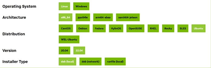
Step 7. Choose the Installation method.
Step 8. Remove Outdated Signing Key:
$ ansible all -m shell -a "sudo apt-key del 7fa2af80"
Step 9. Add the pin file to prioritize CUDA repository:
$ wget https://developer.download.nvidia.com/compute/cuda/repos/ubuntu2204/x86_64/cuda-ubuntu2204.pin
$ scp cuda-ubuntu2204.pin ubuntu@10.29.148.171:/home/ubuntu/
$ ansible all -m copy -a "src=/home/ubuntu/cuda-ubuntu2204.pin dest=/home/ubuntu/cuda-ubuntu2204.pin"
$ ansible all -m command -a "sudo mv /home/ubuntu/cuda-ubuntu2204.pin /etc/apt/preferences.d/cuda-repository-pin-600
Step 10. Install local repository on file system:
$scp cuda-repo-ubuntu2204-12-2-local_12.2.2-535.104.05-1_amd64.deb ubuntu@10.29.148.171:/home/ubuntu/
$ ansible all -m copy -a "src=/home/ubuntu/cuda-repo-ubuntu2204-12-2-local_12.2.2-535.104.05-1_amd64.deb dest=/home/ubuntu/cuda-repo-ubuntu2204-12-2-local_12.2.2-535.104.05-1_amd64.deb"
$ ansible all -m shell -a "sudo dpkg -i /home/ubuntu/cuda-repo-ubuntu2204-12-2-local_12.2.2-535.104.05-1_amd64.deb"
$ ansible all -m command -a "sudo cp /var/cuda-repo-ubuntu2204-12-2-local/cuda-F73B257B-keyring.gpg /usr/share/keyrings/"
Step 11. Update the Apt repository cache:
$ ansible all -m command -a "sudo apt-get update"
Step 12. Install CUDA SDK
$ ansible all -m command -a "sudo apt-get install cuda -y"
Step 13. (optional) To include all GDS packages:
$ ansible all -m command -a "sudo apt-get install -y nvidia-gds"
Step 14. Reboot the system:
$ ansible all -m command -a "sudo reboot"
Post Installation Steps for NVIDIA CUDA
Step 1. Environment Setup:
$ ansible all -m shell -a "export PATH=/usr/local/cuda-12.2/bin${PATH:+:${PATH}}"
Note: When using the runfile installation method, the LD_LIBRARY_PATH variable needs to contain /usr/local/cuda-12.2/lib64 on a 64-bit system, or /usr/local/cuda-12.2/lib on a 32-bit system.
Step 2. To change the environment variables for 64-bit operating systems:
Note: The following paths change when using a custom install path with the runfile installation method.
$ ansible all -m shell -a "export CUDA_HOME=/usr/local/cuda-12.2"
$ ansible all -m shell -a "export PATH=${CUDA_HOME}/bin:${PATH}"
$ ansible all -m shell -a "export LD_LIBRARY_PATH=${CUDA_HOME}/lib64:$LD_LIBRARY_PATH"
Note: Recommended Actions – the following steps are recommended to verify the integrity of the installation.
Step 3. Verify the driver version:
$ ansible all -m command -a "cat /proc/driver/nvidia/version"
hpc-node5 | CHANGED | rc=0 >>
NVRM version: NVIDIA UNIX x86_64 Kernel Module 535.104.05 Sat Aug 19 01:15:15 UTC 2023
GCC version: gcc version 11.4.0 (Ubuntu 11.4.0-1ubuntu1~22.04)
hpc-node4 | CHANGED | rc=0 >>
NVRM version: NVIDIA UNIX x86_64 Kernel Module 535.104.05 Sat Aug 19 01:15:15 UTC 2023
GCC version: gcc version 11.4.0 (Ubuntu 11.4.0-1ubuntu1~22.04)
hpc-node3 | CHANGED | rc=0 >>
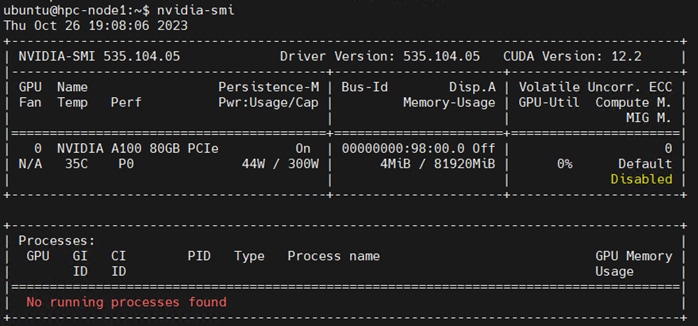
Step 4. Run nvidia-smi command:
Step 1. Based on github for cuda-samples: https://github.com/NVIDIA/cuda-samples:
hpc-node1:/home/ubuntu/cuda-samples/Samples/1_Utilities/bandwidthTest# ./bandwidthTest
[CUDA Bandwidth Test] - Starting...
Running on...
Device 0: NVIDIA A100 80GB PCIe
Quick Mode
Host to Device Bandwidth, 1 Device(s)
PINNED Memory Transfers
Transfer Size (Bytes) Bandwidth(GB/s)
32000000 25.0
Device to Host Bandwidth, 1 Device(s)
PINNED Memory Transfers
Transfer Size (Bytes) Bandwidth(GB/s)
32000000 24.9
Device to Device Bandwidth, 1 Device(s)
PINNED Memory Transfers
Transfer Size (Bytes) Bandwidth(GB/s)
32000000 549.7
Result = PASS
Note: The CUDA Samples are not meant for performance measurements. Results may vary when GPU Boost is enabled.
Prerequisites
Step 1. Download NVIDIA HPC SDK software: https://developer.nvidia.com/hpc-sdk-downloads
$ wget https://developer.download.nvidia.com/hpc-sdk/23.9/nvhpc_2023_239_Linux_x86_64_cuda_multi.tar.gz
$ scp nvhpc_2023_239_Linux_x86_64_cuda_multi.tar.gz ubuntu@10.29.148.171:/home/ubuntu/
Step 2. Copy NVIDIA HPC SDK to all nodes:
$ ansible all -m copy -a "src=/home/ubuntu/nvhpc_2023_239_Linux_x86_64_cuda_multi.tar.gz dest=/home/ubuntu/nvhpc_2023_239_Linux_x86_64_cuda_multi.tar.gz"
$ ansible all -m shell -a "tar xpzf /home/ubuntu/nvhpc_2023_239_Linux_x86_64_cuda_multi.tar.gz"
Step 3. Install NVIDIA HPC SDK (optionally – select where it gets installed):
$ ansible all -m shell -a "tar xpzf /home/ubuntu/nvhpc_2023_239_Linux_x86_64_cuda_multi.tar.gz"
Step 4. Install NVIDIA HPC SDK:
$ su – root
$ cd nvhpc_2023_239_Linux_x86_64_cuda_multi/
$ sudo ./install
Step 5. Press Enter to continue installing NVIDIA HPC SDK:
Step 6. Select Install option:
An auto installation is appropriate for any scenario. The HPC SDK
configuration (localrc) is created at first use and stored in each user's
home directory.
Installation directory? [/opt/nvidia/hpc_sdk]
1 Single system install
2 Network install
3 Auto install
Please choose install option:
3
Step 7. Select default directory or intended location:
Please specify the directory path under which the software will be installed.
The default directory is /opt/nvidia/hpc_sdk, but you may install anywhere
you wish, assuming you have permission to do so.
Installation directory? [/opt/nvidia/hpc_sdk]
| Tech tip |
| Installing NVIDIA HPC SDK version 23.9 into /opt/nvidia/hpc_sdk Making symbolic link in /opt/nvidia/hpc_sdk/Linux_x86_64 generating environment modules for NV HPC SDK 23.9 ... done. Installation complete. HPC SDK successfully installed into /opt/nvidia/hpc_sdk If you use the Environment Modules package, that is, the module load command, the NVIDIA HPC SDK includes a script to set up the appropriate module files. % module load /opt/nvidia/hpc_sdk/modulefiles/nvhpc/23.9 % module load nvhpc/23.9 Alternatively, the shell environment may be initialized to use the HPC SDK. In csh, use these commands: % setenv MANPATH "$MANPATH":/opt/nvidia/hpc_sdk/Linux_x86_64/23.9/compilers/man % set path = (/opt/nvidia/hpc_sdk/Linux_x86_64/23.9/compilers/bin $path) In bash, sh, or ksh, use these commands: $ MANPATH=$MANPATH:/opt/nvidia/hpc_sdk/Linux_x86_64/23.9/compilers/man; export MANPATH $ PATH=/opt/nvidia/hpc_sdk/Linux_x86_64/23.9/compilers/bin:$PATH; export PATH Once the 64-bit compilers are available, you can make the OpenMPI commands and man pages accessible using these commands. % set path = (/opt/nvidia/hpc_sdk/Linux_x86_64/23.9/comm_libs/mpi/bin $path) % setenv MANPATH "$MANPATH":/opt/nvidia/hpc_sdk/Linux_x86_64/23.9/comm_libs/mpi/man And the equivalent in bash, sh, and ksh: $ export PATH=/opt/nvidia/hpc_sdk/Linux_x86_64/23.9/comm_libs/mpi/bin:$PATH $ export MANPATH=$MANPATH:/opt/nvidia/hpc_sdk/Linux_x86_64/23.9/comm_libs/mpi/man Please check https://developer.nvidia.com for documentation, use of NVIDIA HPC SDK software, and other questions.
|
Step 8. Install environement-modules:
$ ansible all -m shell -a "sudo apt-get install -y environment-modules"
$ cat /etc/profile.d/modules.sh
shell=$(/usr/bin/basename $(/bin/ps -p $$ -ocomm=))
if [ -f /usr/share/modules/init/$shell ]; then
. /usr/share/modules/init/$shell
else
. /usr/share/modules/init/sh
fi
Step 9. Create environment variables to be set at the time of user login:
$ vi /etc/environment
# Use the HPC SDK toolkit compilers
export NVIDIA=/opt/hpc/nvidia/hpc_sdk
module use $NVIDIA/modulefiles
module load nvhpc
# But then override their choice of Open MPI to use the HPCX that is inside the HPC SDK
module use /opt/hpc/nvidia/hpc_sdk/Linux_x86_64/2023/comm_libs/12.2/hpcx/hpcx-2.15/modulefiles
module load hpcx
$ source /etc/environment
$printenv
Step 10. Verify above configured modules are loaded and “mpirun” and “mpicc”available:
$ which mpirun
/opt/hpc/nvidia/hpc_sdk/Linux_x86_64/23.7/comm_libs/12.2/hpcx/hpcx-2.15/ompi/bin/mpirun
$ which mpicc
/opt/hpc/nvidia/hpc_sdk/Linux_x86_64/23.7/comm_libs/12.2/hpcx/hpcx-2.15/ompi/bin/mpicc
Solution Validation
This chapter contains the following:
NVIDIA GPUDirect RDMA (Remote Direct Memory Access) is a technology that enables a direct path for data exchange between the GPU and third-party peer devices using standard PCIe features. GPUDirect RDMA relies on the ability of NVIDIA GPUs to expose portions of device memory in a PCIe base address register region, as shown in Figure 12. The GPUDirect technology requires a PCIe Switch to facilitate direct memory transfer between NVIDIA NIC and GPU.
A PCIe switch is not strictly required to enable GPUDirect RDMA on a supported system. Please refer to How GPUDirect RDMA works, NVIDIA GPUDirect Storage design guide, and GPUDirect RDMA supported systems for more details.
If there is no PCIe switch between network interface card and NVIDIA GPU, data has to traverse through processor. Performance improvement achieved through GPUDirect RDMA, and benefits depend on your use case and system configuration.
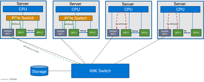
Note: A requirement for GPUDirect RDMA to work is that the NVIDIA GPU and the Mellanox Adapter share the same root complex through a PCIe switch.
Note: For our solution, we could not use GPUDirect as Cisco UCS C240 M7 rack server does not contain PCIe switch between CPU and Mellanox Ethernet NIC and NVIDIA GPU as shown in Figure 12.
NVIDIA HPC-X Software Toolkit Setup and Configuration
This section details the validation of the HPC/AI cluster previously configured.
● Test Result for NVIDIA HPC-X Software Toolkit
● NVIDIA HPC-X Software Toolkit Test Summary
Test toolkit to validate the end-end connectivity.
Note: We installed NVIDIA HPC-X software toolkit version 2.16 for the validation.
For more details, go to: https://docs.nvidia.com/networking/display/hpcxv216
| Tech tip |
| MPI (Message Passing Interface) is a standard and widely used library and protocol for writing parallel applications in HPC. “mpirun” is a command used in HPC part of MPI implementation, such as OpenMPI and MPICH which provides the underlying libraries and runtime support for parallel programming. When combined with these MPI libraries, “mpirun” becomes a powerful tool for launching, managing, and scaling parallel applications in HPC environments, making it possible to harness the computational power of clusters and supercomputers for scientific simulations, data analysis, and other compute-intensive tasks. “mpicc” streamlines the process of compiling parallel C and C++ programs for use in HPC environments, allowing developers to take full advantage of the parallel processing capabilities of these systems. “mpich” is one of the primary implementations of the MPI standard. It provides a set of libraries, tools, and runtime environments that allow developers to create parallel applications in C, C++, and Fortran. OpenACC (Open Accelerators) is an open standard for parallel programming of heterogeneous computer systems, including multi-core CPUs and GPUs (Graphics Processing Units). It provides a set of directives, libraries, and APIs that enable developers to accelerate their applications by offloading compute-intensive portions to accelerators, such as GPUs, while maintaining a single source code that can run on both CPUs and GPUs. UCX (Unified Communication X) s an open-source communication library designed for high-performance computing (HPC) and other parallel computing environments. UCX is particularly valuable for applications that rely on efficient communication in HPC and parallel computing scenarios. It allows these applications to achieve high performance while maintaining portability across diverse hardware and networking environments. |
Step 1. Accept EUL agreement to download NVIDIA HPC-X clusterkit:
Step 2. Copy HPC-X software toolkit on all nodes:
$ scp hpcx-v2.16-gcc-mlnx_ofed-ubuntu22.04-cuda12-gdrcopy2-nccl2.18-x86_64.tbz ubuntu@10.29.148.171:/home/ubuntu/
$ ansible all -m copy -a "src=/home/ubuntu/hpcx-v2.16-gcc-mlnx_ofed-ubuntu22.04-cuda12-gdrcopy2-nccl2.18-x86_64.tbz dest=/home/ubuntu/hpcx-v2.16-gcc-mlnx_ofed-ubuntu22.04-cuda12-gdrcopy2-nccl2.18-x86_64.tbz"
Step 3. Extract HPC-X software toolkit:
$ ansible all -m shell -a "tar -xvf /home/ubuntu/hpcx-v2.16-gcc-mlnx_ofed-ubuntu22.04-cuda12-gdrcopy2-nccl2.18-x86_64.tbz"
Step 4. Update shell variable of the location of HPC-X installation:
$ cd /home/ubuntu/hpcx-v2.16-gcc-mlnx_ofed-ubuntu22.04-cuda12-gdrcopy2-nccl2.18-x86_64
$ export HPCX_HOME=$PWD
Step 5. Build and Run applications with HPC-X. To load OpenMPI based package run following commands:
$ source $HPCX_HOME/hpcx-init.sh
$ hpcx_load
$ env | grep HPCX
$ mpicc $HPCX_MPI_TESTS_DIR/examples/hello_c.c -o $HPCX_MPI_TESTS_DIR/examples/hello_c
$ mpirun -np 2 $HPCX_MPI_TESTS_DIR/examples/hello_c
Hello, world, I am 0 of 2, (Open MPI v4.1.5rc2, package: Open MPI root@hpc-kernel-03 Distribution, ident: 4.1.5rc2, repo rev: v4.1.5rc1-17-gdb10576f40, Unreleased developer copy, 150)
Hello, world, I am 1 of 2, (Open MPI v4.1.5rc2, package: Open MPI root@hpc-kernel-03 Distribution, ident: 4.1.5rc2, repo rev: v4.1.5rc1-17-gdb10576f40, Unreleased developer copy, 150)
$ oshcc $HPCX_MPI_TESTS_DIR/examples/hello_oshmem_c.c -o $HPCX_MPI_TESTS_DIR/examples/hello_oshmem_c
$ oshrun -np 2 $HPCX_MPI_TESTS_DIR/examples/hello_oshmem_c
Hello, world, I am 1 of 2: http://www.open-mpi.org/ (version: 1.4)
Hello, world, I am 0 of 2: http://www.open-mpi.org/ (version: 1.4)
$ hpcx_unload
Step 6. Run following command: (optional) If not installed already; install environment-modules:
$ ansible all -m shell -a “sudo apt install environment-modules -y”
$ ansible all -m shell -a “source ~/.bashrc”
$ ansible all -m shell -a “source ~/.profile”
$ ansible all -m shell -a “sudo modprobe knem”
Step 7. Building HPC-X with Intel Compiler Suite:
Note: As of version 1.7, HPC-X builds are no longer distributed based on the Intel compiler suite. However, after following the HPC-X deployment example below, HPC-X can subsequently be rebuilt from source with your Intel compiler suite as follows:
$ tar xfp ${HPCX_HOME}/sources/openmpi-gitclone.tar.gz
$ cd ${HPCX_HOME}/sources/openmpi-gitclone
$ ls -l ${HPCX_HOME}/sources/openmpi-gitclone.tar.gz
-rw-r--r-- 1 ubuntu ubuntu 18287983 Aug 3 13:59 /home/ubuntu/hpcx-v2.16-gcc-mlnx_ofed-ubuntu22.04-cuda12-gdrcopy2-nccl2.18-x86_64//sources/openmpi-gitclone.tar.gz
$ cd ${HPCX_HOME}/sources/openmpi-gitclone
$ ./configure CC=icx CXX=icpx F77=ifort FC=ifort --prefix=${HPCX_HOME}/ompi-icc \
--with-hcoll=${HPCX_HOME}/hcoll \
--with-ucx=${HPCX_HOME}/ucx \
--with-platform=contrib/platform/mellanox/optimized \
2>&1 | tee config-icc-output.log
$ make -j32 all 2>&1 | tee build_icc.log && make -j24 install 2>&1 | tee install_icc.log
Step 8. Load HPC-X environment from modules:
$ module use $HPCX_HOME/modulefiles
$ module load hpcx
$ mpicc $HPCX_MPI_TESTS_DIR/examples/hello_c.c -o $HPCX_MPI_TESTS_DIR/examples/hello_c
$ mpirun -np 2 $HPCX_MPI_TESTS_DIR/examples/hello_c
Hello, world, I am 1 of 2, (Open MPI v4.1.5rc2, package: Open MPI root@hpc-kernel-03 Distribution, ident: 4.1.5rc2, repo rev: v4.1.5rc1-17-gdb10576f40, Unreleased developer copy, 150)
Hello, world, I am 0 of 2, (Open MPI v4.1.5rc2, package: Open MPI root@hpc-kernel-03 Distribution, ident: 4.1.5rc2, repo rev: v4.1.5rc1-17-gdb10576f40, Unreleased developer copy, 150)
$ oshcc $HPCX_MPI_TESTS_DIR/examples/hello_oshmem_c.c -o $HPCX_MPI_TESTS_DIR/examples/hello_oshmem_c
$ oshrun -np 2 $HPCX_MPI_TESTS_DIR/examples/hello_oshmem_c
Hello, world, I am 1 of 2: http://www.open-mpi.org/ (version: 1.4)
Hello, world, I am 0 of 2: http://www.open-mpi.org/ (version: 1.4)
Step 9. To profile MPI API run following command: (Optional)
$ export IPM_KEYFILE=$HPCX_IPM_DIR/etc/ipm_key_mpi
$ export IPM_LOG=FULL
$ export LD_PRELOAD=$HPCX_IPM_DIR/lib/libipm.so
$ $HPCX_IPM_DIR/bin/ipm_parse -html outfile.xml
$ export IPM_ADD_BARRIER_TO_REDUCE=1
$ export IPM_ADD_BARRIER_TO_ALLREDUCE=1
$ export IPM_ADD_BARRIER_TO_GATHER=1
$ export IPM_ADD_BARRIER_TO_ALL_GATHER=1
$ export IPM_ADD_BARRIER_TO_ALLTOALL=1
$ export IPM_ADD_BARRIER_TO_ALLTOALLV=1
$ export IPM_ADD_BARRIER_TO_BROADCAST=1
$ export IPM_ADD_BARRIER_TO_SCATTER=1
$ export IPM_ADD_BARRIER_TO_SCATTERV=1
$ export IPM_ADD_BARRIER_TO_GATHERV=1
$ export IPM_ADD_BARRIER_TO_ALLGATHERV=1
$ export IPM_ADD_BARRIER_TO_REDUCE_SCATTER=1
Step 10. Create hotfile.txt in /home/ubuntu/hpcx-v2.16-gcc-mlnx_ofed-ubuntu22.04-cuda12-gdrcopy2-nccl2.18-x86_64/clusterkit/bin/
$ vi hostfile.txt
hpc-node1
hpc-node2
hpc-node3
….
hpc-node8
Step 11. UCX intra-node communication uses the KNEM module, which improves the performance significantly. Make sure this module is loaded on your system:
$ modprobe knem
Step 12. When HPC-X is launched with Open MPI without a resource manager job environment (slurm,pbs, and so on), or when it is launched from a compute node, the default rsh/ssh-based launcher will be used. This launcher does not propagate environment variables to the compute nodes. Thus, it is important to ensure the propagation of LD_LIBRARY_PATH variable from HPC-x is done as follows:
$ mpirun -x LD_LIBRARY_PATH -np 2 -H hpc-node1,hpc-node2,hpc-node3,hpc-node4 $HPCX_MPI_TESTS_DIR/examples/hello_c
Sample Command:
$ mpirun -x LD_LIBRARY_PATH -np 2 -H host1,host2 $HPCX_MPI_TESTS_DIR/examples/hello_c
Step 13. After loading HPC-X package; run clusterkit script or using the “mpirun” command:
# mpirun
$ mpirun -x LD_LIBRARY_PATH -np 2 -H c240m7-13,c240m7-14 $HPCX_CLUSTERKIT_DIR/bin/clusterkit
Note: ClusterKit runs by default in pairwise test cases, which requires at least two nodes to run.
# clusterkit script
Note: $ ./clusterkit.sh -h for list of options and parameters.
Test Results for NVIDIA HPC-X Software Toolkit
Clusterkit part of the NVIDIA HPC-X software toolkit is a multifaceted node assessment tool for high performance clusters. Currently, ClusterKit is capable of testing latency, bandwidth, effective bandwidth, memory bandwidth, GFLOPS by node, per-rack collective performance, as well as bandwidth and latency between GPUs and local/remote memory. ClusterKit employs well known techniques and tests to arrive at these performance metrics and is intended to give the user a general look at the health and performance of a cluster.
Step 1. A sample command ran to measure performance and HPC/AI cluster configuration for this solution test and validate:
$ ./clusterkit.sh --ssh --hostfile hostfile.txt -y --hca_list "mlx5_0:1,mlx5_1:1" -z 15
Note: mlx5_0 and mlx5_1 are two physical ports on ConnectX6-DX ethernet NIC installed on each Cisco UCS C240 M7 Rack Server
Step 2. Test result generated by HPC-X Clusterkit command which runs for 15 minute interval can be found here:
~/hpcx-v2.16-gcc-mlnx_ofed-ubuntu22.04-cuda12-gdrcopy2-nccl2.18-x86_64/clusterkit/bin/20231103_134557$ cat bandwidth.txt
Cluster: Unknown
User: ubuntu
Testname: bandwidth
Date_and_Time: 2023/11/03 13:45:58
JOBID: 0
PPN: 128
Bidirectional: True
Skip_Intra_Node: True
HCA_Tag: Unknown
Technology: Unknown
Bandwidth_bidir (MB/s):
Message size: 8388608 B Iterations: 10000
Rank: 0 1 2 3 4 5 6 7
0 (hpc-node1): 0.0 48829.3 48381.3 48377.6 48823.9 48840.8 48839.7 48842.8
1 (hpc-node2): 48829.3 0.0 48393.2 48372.8 48841.4 48853.4 48856.3 48853.9
2 (hpc-node3): 48381.3 48393.2 0.0 48347.1 48396.5 48387.9 48389.8 48382.1
3 (hpc-node4): 48377.6 48372.8 48347.1 0.0 48369.2 48378.3 48367.7 48374.7
4 (hpc-node5): 48823.9 48841.4 48396.5 48369.2 0.0 48839.0 48842.8 48839.5
5 (hpc-node6): 48840.8 48853.4 48387.9 48378.3 48839.0 0.0 48857.7 48865.4
6 (hpc-node7): 48839.7 48856.3 48389.8 48367.7 48842.8 48857.7 0.0 48859.3
7 (hpc-node8): 48842.8 48853.9 48382.1 48374.7 48839.5 48865.4 48859.3 0.0
Minimum bandwidth: 48347.1 MB/s between hpc-node3 and hpc-node4
Maximum bandwidth: 48865.4 MB/s between hpc-node6 and hpc-node8
Average bandwidth: 48628.7 MB/s
NVIDIA HPC-X Software Toolkit Test Summary
When running NVIDIA HPC-X Software toolkit based Clusterkit test; we observed ~200Gbps bandwidth is achieved (Duplex on two 100Gbps port; mlx5_0 and mlx5_1 are two physical ports on ConnectX6-DX ethernet NIC installed on each Cisco UCS C240 M7 Rack Server) when measuring host connectivity bandwidth between Cisco UCS C240 M7 server and a pair of Cisco Nexus 93600CD-GX leaf switch.
The following screenshot shows line-rate network traffic generated when running NVIDIA HPC-X Clusterkit command above to measure network bandwidth for longer duration. Line-rate traffic was monitored between Cisco UCS C240 M7 with Mellanox ConnectX-6 ethernet NIC ports connected to a pair of Cisco Nexus 93600CD-GX leaf switch.
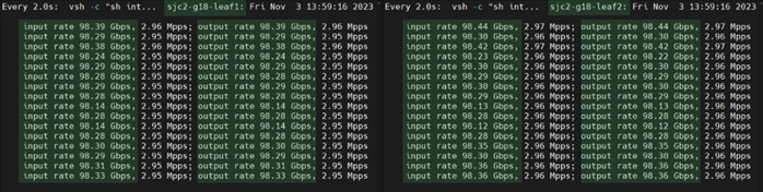
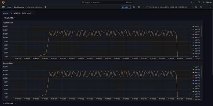
Test
This section highlights test result for the datasets of different size and application area. Tests were executed to determine cluster scalability, clock time required to complete each said dataset on CPU only and repeat the same on a system with one or two GPU per system.
CPU only tests were executed with all logical cores utilized on each node via adding parameter -np 128*x (x= multiplier representative of number of nodes utilized).
We captured system performance statistics such as CPU utilization (vmstat), GPU utilization (nvidia-smi and NVIDIA GPU exporter Grafana WebUI console) and Network port utilization on Cisco Nexus switch connected to Cisco UCS server and NetApp A400 Storage when running the same test in a clustered configuration.
We tested combination of one, two, four and eight nodes to showcase linear scalability of the solution.
Test result shows clock time in second to complete each test scenario whether running on CPU or GPU.
HPC Workload Dataset
Prerequisites
We tested documented solution with HPC datasets representing different area/applications list below:
Note: Workload listed is for the proof of concept (PoC) purpose only.
1. The MiniWeather Mini App (Weather)
The miniWeather code mimics the basic dynamics seen in atmospheric weather and climate. The dynamics themselves are dry compressible, stratified, non-hydrostatic flows dominated by buoyant forces that are relatively small perturbations on a hydrostatic background state. The equations in this code themselves form the backbone of pretty much all fluid dynamics codes, and this particular flavor forms the base of all weather and climate modeling.
For more details: https://github.com/mrnorman/miniWeather#openacc-accelerator-threading
2. Minisweep (Nuclear Engineering)
Minisweep is a deterministic Sn radiation transport miniapp used for performance optimization and performance model evaluation on HPC architectures.
For more details: https://github.com/wdj/minisweep
3. HPGMG: High-performance Geometric Multigrid (Cosmology/Astrophysics)
HPGMG implements full multigrid (FMG) algorithms using finite-volume and finite-element methods. Different algorithmic variants adjust the arithmetic intensity and architectural properties that are tested. These FMG methods converge up to discretization error in one F-cycle, thus may be considered direct solvers. An F-cycle visits the finest level a total of two times, the first coarsening (8x smaller) 4 times, the second coarsening 6 times, etc.
For more details: https://bitbucket.org/hpgmg/hpgmg/src/master/
| Tech tip |
| Run the following command to find all the parameter. $mpicc –help Subset is pasted below from “mpicc --help” for reference: Target-specific switches: -acc[=gpu|host|multicore|[no]autopar|[no]routineseq|legacy|strict|verystrict|sync|[no]wait] Enable OpenACC directives gpu OpenACC directives are compiled for GPU execution only; please refer to -gpu for target specific options host Compile for serial execution on the host CPU multicore Compile for parallel execution on the host CPU [no]autopar Enable (default) or disable loop autoparallelization within acc parallel [no]routineseq Compile every routine for the device legacy Suppress warnings about deprecated PGI accelerator directives strict Issue warnings for non-OpenACC accelerator directives verystrict Fail with an error for any non-OpenACC accelerator directive sync Ignore async clauses [no]wait Wait for each device kernel to finish |
The workload dataset tested in this solution to create a baseline has minimum system requirement based on the application and dataset size. Intention is to target varied cluster sizes with node count, core count and GPU count and their relative impact when running benchmark application to determined overall cluster performance.
● The Small size dataset - target a single larger node or a small cluster of nodes using between 64 and 1024 ranks. It uses a maximum of 480GB of memory per benchmark.
● The Medium size dataset - target a mid-sized cluster of nodes using between 256 and 4096 ranks. It uses a maximum of 4TB of memory per benchmark.
● The Large size dataset - target a larger cluster of nodes using between 2048 and 32,768 ranks. It uses a maximum of 14.5TB of memory per benchmark.
For this solution, datasets were downloaded and configured in the shared NFS volume on NetApp A400 storage and used NetApp FlexClone volumes to mount on each node part of the HPC cluster test. We tested following possible combinations for scale tests on HPC cluster workloads.
Table 6. Configuration tested for scale tests
| Scale Test |
1-node |
2-node |
4-node |
8-node |
| C240M7 Server with 1x A100 GPU |
|
|
|
|
| C240M7 Server with 2x A100 GPU |
|
|
|
|
| C240M7 Server with CPU only |
|
|
|
|
Note: We will extend this exercise with 8 node HPC cluster with 2 x NVIDIA Tesla A100-80G GPU per node in the future.
Application 1: miniWeather (Large Size Dataset)
Table 7 lists the results from scale out tests on miniWeather.
Table 7. Scale test results with miniWeather large size dataset in second
| Scale Test |
1-node (Total time in second) |
2-node (Total time in second) |
4-node (Total time in second) |
8-node (Total time in second) |
| C240M7 Server with 1x A100 GPU |
1048.16 |
518.98 |
246.16 |
109.27 |
| C240M7 Server with 2x A100 GPU |
518.34 |
245.61 |
105.85 |
NA |
| C240M7 Server with CPU only |
3418.28 |
1726.53 |
865.28 |
436.14 |
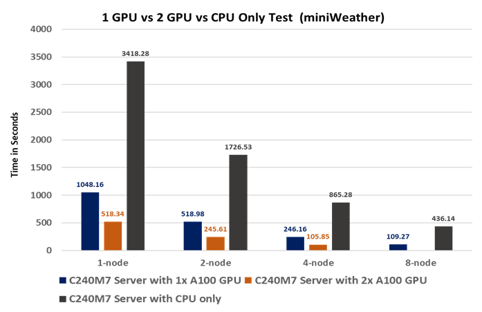
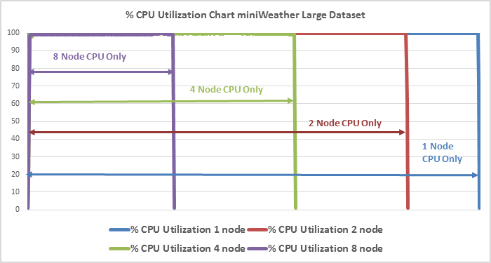
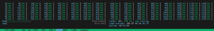
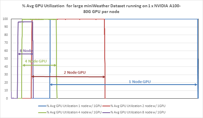
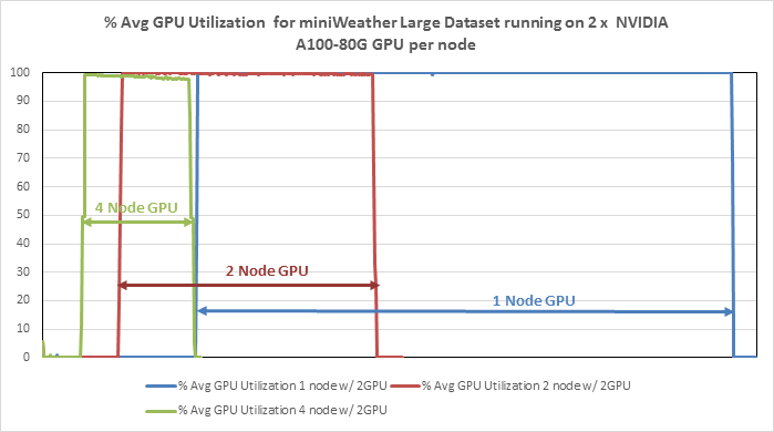
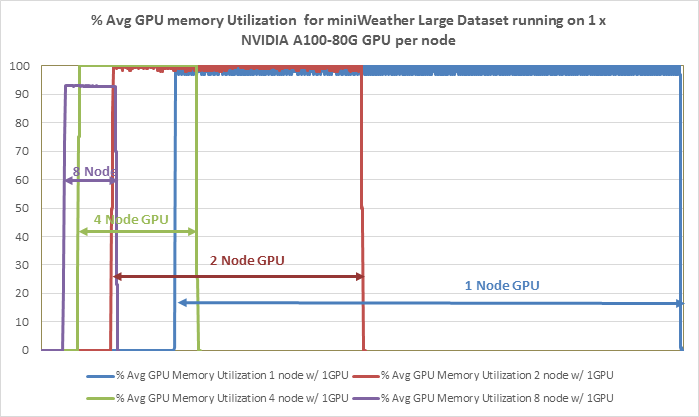
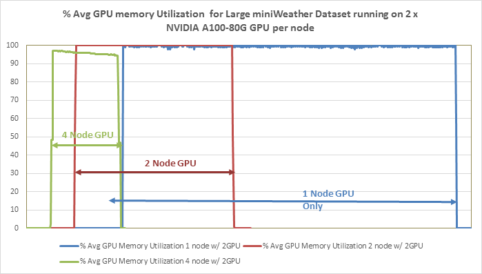
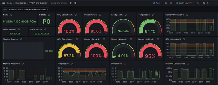
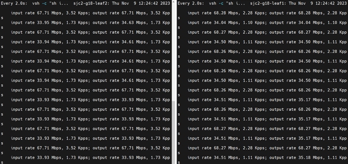
Observations
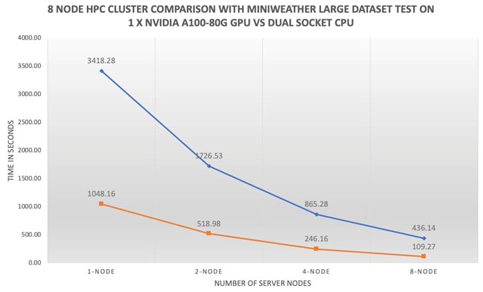
The following observations were made from the test results obtained by running miniWeather large dataset on the 8 x Cisco UCS C240 M7 node based HPC cluster as defined in this solution study:
● The end-end FlexPod HPC cluster as highlighted in this solution scaled linearly whether the cluster test ran by CPU only or w/ GPU.
● Each node resources i.e., compute, storage and network consumed evenly throughout the cluster test.
● 100% GPU utilization and memory utilization.
● No CPU cycles were consumed when ran the test on NVIDIA A100-80G GPU.
● Time to complete the test with one GPU per node in an eight-node cluster is 4x faster than running the same test on eight-node cluster without GPU.
Application 2: Minisweep (Small Size Dataset)
Table 8 lists the results from scale out tests on Minisweep.
Table 8. Scale test results with Minisweep small size dataset in second
| Scale Test |
1-node (Total time in second) |
2-node (Total time in second) |
4-node (Total time in second) |
8-node (Total time in second) |
| C240M7 Server with 1x A100 GPU |
438.10 |
217.18 |
122.93 |
76.21 |
| C240M7 Server with 2x A100 GPU |
216.99 |
130.58 |
87.10 |
NA |
| C240M7 Server with CPU only |
1927.84 |
1045.48 |
742.04 |
435.59 |
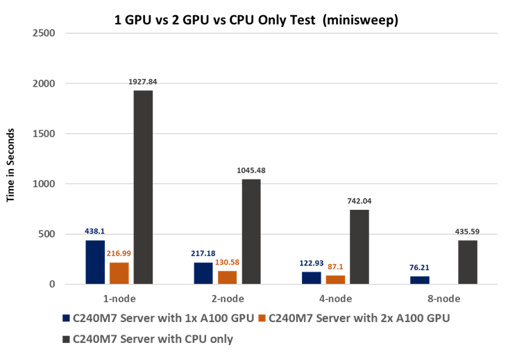
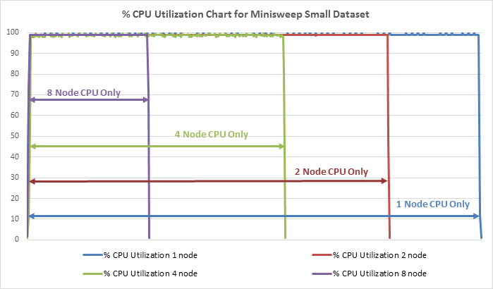
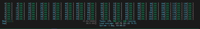
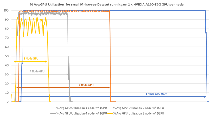
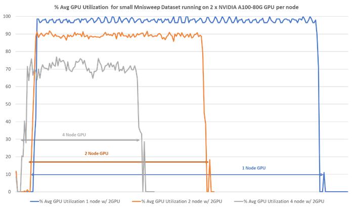
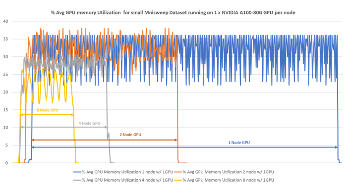
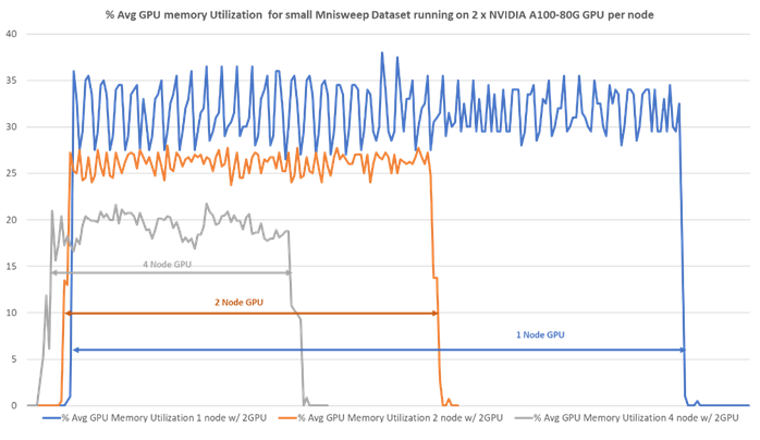
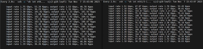
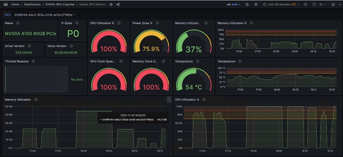
Observations
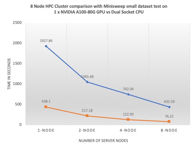
The following observations were made from the test results obtained by running Minisweep small dataset on the 8 x Cisco UCS C240 M7 node based HPC cluster as defined in this solution study:
● The end-end FlexPod HPC cluster as highlighted in this solution scaled linearly whether the cluster test ran by CPU only or w/ GPU.
● Each node resources i.e., compute, storage and network consumed evenly throughout the cluster test.
● Different than weather simulation exercise above the Nuclear Engineering - Radiation Transport based Minisweep small dataset showed difference in overall GPU utilization; while we saw at the full cluster test approximately 90% GPU utilization and 70% memory utilization.
● No CPU cycles were consumed when ran the test on NVIDIA A100-80G GPU.
● Time to complete the test with one GPU per node in an eight-node cluster is 5.7x faster than running the same test on eight-node cluster without GPU.
Application 3: HPGMG (Medium Size Dataset)
Table 9 lists the results from scale out tests on HPGMG.
Table 9. Scale test results with HPGMG medium size dataset in second.
| Scale Test |
1-node (Total time in second) |
2-node (Total time in second) |
4-node (Total time in second) |
8-node (Total time in second) |
| C240M7 Server with 1x A100 GPU |
NA |
NA |
308.76 |
190.16 |
| C240M7 Server with 2x A100 GPU |
NA |
305.33 |
182.86 |
NA |
| C240M7 Server with CPU only |
4524.42 |
2330.06 |
1229.69563 |
677.1356146 |
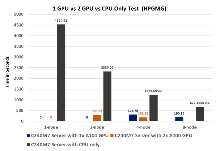
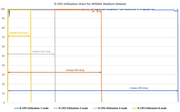
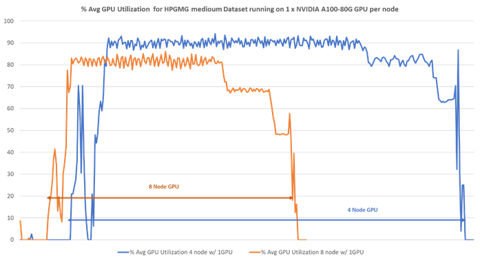
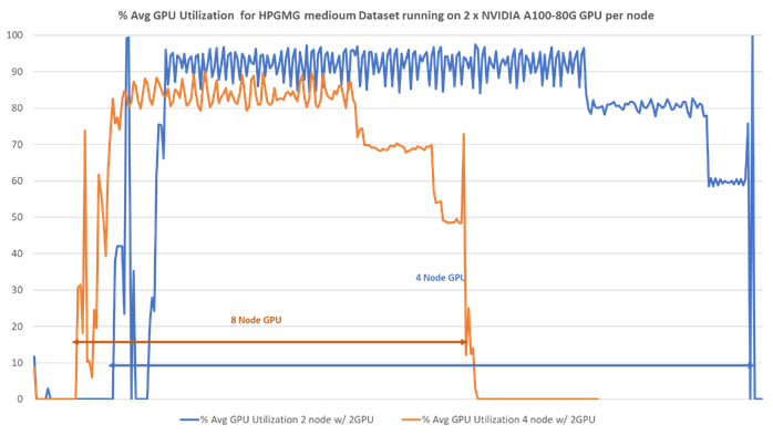
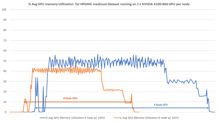
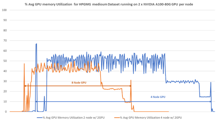
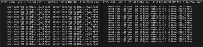
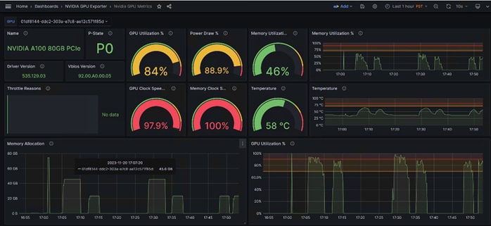
Observations
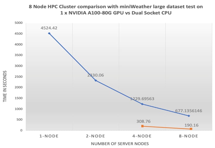
The following observations were made from the test results obtained by running HPGMG medium dataset on the 8 x Cisco UCS C240 M7 node based HPC cluster as defined in this solution study:
● Depends on the workload and dataset size more GPU is required. HPGMG medium dataset consumed.
● The end-end FlexPod HPC cluster as highlighted in this solution scaled linearly whether the cluster test ran by CPU only or w/ GPU.
● Each node resources i.e., compute, storage and network consumed evenly throughout the cluster test.
● Compared to miniWeather and Minisweep test exercise above HPGMG medium dataset which is targeting application area of Cosmology, Astrophysics, Combustion showed 80% GPU utilization and 40% memory utilization.
● Due to the minimum memory required to execute the HPGMG medium dataset was higher than other two dataset we were not able to run the test on 1 GPU or 2 GPU in a single system.
● No CPU cycles were consumed when ran the test on NVIDIA A100-80G GPU.
● Time to complete the test with one GPU per node in an eight-node cluster is 3.5x faster than running the same test on eight-node cluster without GPU.
The amalgamation of High-Performance Computing (HPC) and Artificial Intelligence (AI) represents a powerful synergy that unleashes unprecedented computational capabilities, enabling us to tackle complex and data-intensive challenges with greater speed, accuracy, and efficiency. The combination of CPUs and GPUs with high-speed data fabric with end-end 100GbE network is essential for achieving optimal performance, scalability, and responsiveness.
Here's the importance of each component because it allows for the best of HPC and AI worlds:
● Diverse Workload Support: CPUs are essential for handling diverse tasks, including system management, control flow, and sequential processes, making them crucial for both HPC and AI infrastructure.
● Parallel Processing: GPUs are vital for parallelizable workloads, such as deep learning and scientific simulations, where their massive parallel processing power accelerates complex calculations.
● Task Offloading: Combining CPUs and GPUs allows for intelligent task distribution, enabling CPUs to offload parallel workloads to GPUs for enhanced efficiency and speed.
● Optimal Performance: Together, CPUs and GPUs offer a balanced and high-performance computing environment, capable of handling a wide range of workloads seamlessly.
● Energy Efficiency: CPUs are generally more power-efficient for certain tasks and are important for overall system management. GPUs, on the other hand, excel in computational throughput. Combining the two can lead to better energy efficiency and performance.
● Fast data pipeline: Data intensive workloads of HPC and AI often involve large datasets. A 100GbE network provides an extensive data pipeline, ensuring efficient data exchange between CPUs, GPUs, storage rapidly and without bottlenecks, improving overall performance.
● Low Latency: Low-latency communication is crucial for HPC and AI workloads, as it reduces the time spent waiting for data transfers and results in faster overall processing.
● Scalability: High-speed networking supports the scaling of resources, enabling you to add more compute nodes, GPUs, or storage as needed for growing workloads.
● Resource Utilization: CPUs and GPUs are fully utilized as data moves quickly between them, minimizing idle times and maximizing the overall system efficiency.
In this solution study, we tested various application (use cases) targeted for weather simulation (miniWeather), Nuclear Engineering - Radiation Transport (Minisweep), and Cosmology, Astrophysics, Combustion (HPGMG).
We documented recommended tunable parameters to achieve balanced configuration amongst compute, network and storage components and proved near linear scalability of the solution as the size of the cluster grew from 1 to 8 node.
Hardik Patel, Technical Marketing Engineer, Cloud and Compute Product Group, Cisco Systems, Inc.
Hardik Patel is a Solution Architect in Cisco System’s Cloud and Compute Engineering Group. Hardik has over 15 years of experience in datacenter solutions and technologies. He is currently responsible for design and architect of next-gen infrastructure solutions and performance in AI/ML and analytics. Hardik holds a Master of Science degree in Computer Science with various career-oriented certification in virtualization, network, and Microsoft.
Tushar Patel, Distinguished Technical Marketing Engineer, Cloud and Compute Product Group, Cisco Systems, Inc.
Tushar Patel is a Solution Architect in Cisco System’s Cloud and Compute Engineering Group. Tushar has 25+ years of experience in datacenter solutions and emerging technologies focusing on Databases, Virtualization, Clustering and Storage technologies. For last 5 years, he has been leading Cisco UCS AI/ML strategy and solutions design for next-gen infrastructure.
Acknowledgements
For their support and contribution to the design, validation, and creation of this Cisco Validated Design, the authors would like to thank:
● Arthur Raefsky, Principal Software Engineer, Cisco Systems, Inc.
● Jeff Squyres, Principal Software Engineer, Cisco Systems, Inc.
● Vijay Durairaj, Technical Marketing Engineering, Cisco Systems, Inc.
● Rajendra Yogendra, Technical Marketing Engineering, Cisco Systems, Inc.
● Esteban Marin, Lead Software Engineer, Cisco Systems, Inc.
● Bobby Oomen, Sr. Manager FlexPod Solutions, NetApp
This appendix contains the following:
● Appendix A - Bill of Materials
● Appendix B - Cisco Nexus 9000 Switch Configuration
● Appendix C - NetApp AFF A400 Storage Configuration
● Appendix D - Monitor GPU Utilization
● Appendix E - References used in this guide
● Appendix F - Recommended for you
Appendix A – Bill of Materials
Table 10 lists the bill of materials for the Cisco UCS C240 M7.
Table 11 lists the bill of materials for the Cisco Nexus 93600CD-GX
Table 10. Bill of Material for Cisco UCS C240 M7
| Part ID |
Description |
Qty |
| UCS-M7-MLB |
UCS M7 RACK MLB |
1 |
| DC-MGT-SAAS |
Cisco Intersight SaaS |
1 |
| DC-MGT-IS-SAAS-ES |
Infrastructure Services SaaS/CVA - Essentials |
8 |
| SVS-DCM-SUPT-BAS |
Basic Support for DCM |
1 |
| DC-MGT-UCSC-1S |
UCS Central Per Server - 1 Server License |
8 |
| UCSC-C240-M7SX |
UCS C240M7 Rack w/oCPU, mem, drv, 2Uw24SFF HDD/SSD backplane |
8 |
| UCSC-GPUAD-C240M7 |
GPU AIR DUCT FOR C240M7 |
8 |
| UCS-M2-960G-D |
960GB M.2 SATA Micron G2 SSD |
16 |
| UCS-M2-HWRAID-D |
Cisco Boot optimized M.2 Raid controller |
8 |
| UCSX-TPM-002C-D |
TPM 2.0, TCG, FIPS140-2, CC EAL4+ Certified, for servers |
8 |
| UCSC-RAIL-D |
Ball Bearing Rail Kit for C220 & C240 M7 rack servers |
8 |
| CIMC-LATEST-D |
IMC SW (Recommended) latest release for C-Series Servers. |
8 |
| UCSC-HSLP-C220M7 |
UCS C220 M7 Heatsink for & C240 GPU Heatsink |
16 |
| UCSC-BBLKD-M7 |
UCS C-Series M7 SFF drive blanking panel |
176 |
| UCS-DDR5-BLK |
UCS DDR5 DIMM Blanks |
128 |
| UCSC-RISAB-24XM7 |
UCS C-Series M7 2U Air Blocker GPU only |
8 |
| CBL-FNVME-C240M7 |
C240M7 NVMe CABLE, MB P-4 to BP (NVMe 3-4) |
8 |
| UCSC-M2EXT-240-D |
C240M7 2U M.2 Extender board |
8 |
| UCS-P100CBL-240-D |
C240M7 NVIDIA P100 /A100 /A40 / A16 / A30 Cable |
16 |
| UCS-CPU-I6448H |
Intel I6448H 2.4GHz/250W 32C/60MB DDR5 4800MT/s |
16 |
| UCS-MRX64G2RE1 |
64GB DDR5-4800 RDIMM 2Rx4 (16Gb) |
128 |
| UCSC-RIS1C-24XM7 |
UCS C-Series M7 2U Riser 1C PCIe Gen5 (2x16) |
8 |
| UCSC-RIS2C-24XM7 |
UCS C-Series M7 2U Riser 2C PCIe Gen5 (2x16) (CPU2) |
8 |
| UCSC-RIS3B-24XM7 |
UCS C-Series M7 2U Riser 3B support rear SAS & NVMe Drives |
8 |
| UCS-NVME4-1920-D |
1.9TB 2.5in U.2 15mm P5520 Hg Perf Med End NVMe |
32 |
| UCSC-P-MCD100GF-D |
Cisco-MLNX MCX623106AC-CDAT 2x100GbE QSFP56 PCIe NIC |
8 |
| UCSC-GPUA100-80-D |
TESLA A100, PASSIVE, 300W, 80GB |
8 |
| NV-GRID-OPT-OUT-D |
NVIDIA GRID SW OPT-OUT |
8 |
| UCSC-GPUA100-80-D |
TESLA A100, PASSIVE, 300W, 80GB |
8 |
| NV-GRID-OPT-OUT-D |
NVIDIA GRID SW OPT-OUT |
8 |
| UCSC-PSU1-2300W-D |
Cisco UCS 2300W AC Power Supply for Rack Servers Titanium |
16 |
| CAB-C19-CBN |
Cabinet Jumper Power Cord, 250 VAC 16A, C20-C19 Connectors |
16 |
| UCS-SID-INFR-UNK-D |
Unknown |
8 |
| UCS-SID-WKL-UNK-D |
Unknown |
8 |
| CON-OSP-UCSCPC34 |
SNTC-24X7X4OS UCS C240M7 Rack w/oCPU, mem, drv, 2Uw24S |
8 |
Table 11. Bill of Material for Cisco Nexus 93600CD-GX
| Part ID |
Description |
Qty |
| N9K-C93600CD-GX |
Nexus 9300 with 28p 100G and 8p 400G |
2 |
| NXK-AF-PI |
Dummy PID for Airflow Selection Port-side Intake |
2 |
| MODE-NXOS |
Mode selection between ACI and NXOS |
2 |
| NXOS-9.3.10 |
Nexus 9500, 9300, 3000 Base NX-OS Software Rel 9.3.10 |
2 |
| NXK-ACC-KIT-1RU |
Nexus 3K/9K Fixed Accessory Kit, 1RU front and rear removal |
2 |
| NXA-FAN-35CFM-PI |
Nexus Fan, 35CFM, port side intake airflow |
12 |
| NXA-PAC-1100W-PI2 |
Nexus AC 1100W PSU - Port Side Intake |
4 |
| CAB-C13-C14-AC |
Power cord, C13 to C14 (recessed receptacle), 10A |
4 |
| C1-SUBS-OPTOUT |
OPT OUT FOR "Default" DCN Subscription Selection |
2 |
| CON-SNC-N9KC936G |
SNTC-NCD Nexus 9300 with 28p 100G and 8p 400G |
2 |
Appendix B – Cisco Nexus 9000 Switch Configuration
Procedure 1. Virtual Port-Channel (vPC) Configuration
A port channel bundles individual links into a channel group to create a single logical link that provides the aggregate bandwidth of up to eight physical links. If a member port within a port channel fails, traffic previously carried over the failed link switches to the remaining member ports within the port channel. Port channeling also load balances traffic across these physical interfaces. The port channel stays operational as long as at least one physical interface within the port channel is operational. Using port channels, Cisco NX-OS provides wider bandwidth, redundancy, and load balancing across the channels.
In the Cisco Nexus Switch topology, a single vPC feature is enabled to provide HA, faster convergence in the event of a failure, and greater throughput. The Cisco Nexus vPC configurations with the vPC domains and corresponding vPC names and IDs for Oracle Database Servers are listed in Table 12.
| vPC Domain |
vPC Name |
vPC ID |
| 18 |
Peer-Link |
1 |
| 18 |
vPC Storage A |
13 |
| 18 |
vPC Storage B |
14 |
As listed in Table 12, a single vPC domain with Domain ID 1 is created across two Nexus switches to define vPC members to carry specific VLAN network traffic. In this topology, we defined a total number of 11 vPCs.
vPC ID 1 is defined as Peer link communication between the two Cisco Nexus switches. vPC IDs 13 and 14 are configured between both Cisco Nexus Switches and NetApp Storage Controller. vPC IDs 71-78 are configured between Mellanox ConnectX-6 Ehternet network interface card (NIC) ports on each Cisco UCS C240 M7 server connecting to Cisco Nexus Switches.
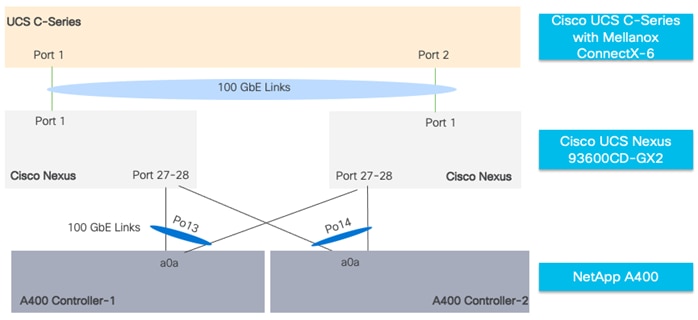
Procedure 2. Create Virtual Port-Channel Domain
Step 1. Login as admin user into the Cisco Nexus A switch, run the following commands:
vpc domain 18
peer-keepalive destination 10.29.148.12 source 10.29.148.11
delay restore 150
peer-gateway
auto-recovery
ip arp synchronize
role priority 10
Step 2. Login as admin user into the Cisco Nexus B switch, run the following commands:
vpc domain 18
peer-keepalive destination 10.29.148.11 source 10.29.148.12
delay restore 150
peer-gateway
auto-recovery
ip arp synchronize
role priority 20
interface Ethernet1/33
description Peer link connected to Leaf3-Spine1
switchport mode trunk
switchport trunk allowed vlan 1,110,160,248
priority-flow-control mode on
interface Ethernet1/34
description Peer link connected to Leaf3-Spine1
switchport mode trunk
switchport trunk allowed vlan 1,110,160,248
priority-flow-control mode on
interface Ethernet1/35
description Peer link connected to Leaf3-Spine2
switchport mode trunk
switchport trunk allowed vlan 1,110,160,248
priority-flow-control mode on
interface Ethernet1/36
description Peer link connected to Leaf3-Spine2
switchport mode trunk
switchport trunk allowed vlan 1,110,160,248
Step 1. Repeat this procedure on Cisco Nexus B switch.
Procedure 3. Create Virtual Port-Channel between Cisco Nexus and NetApp Storage
Step 1. Login as admin user into the Cisco Nexus A switch, run the following commands:
interface port-channel13
description PC-NetApp-A
switchport mode trunk
switchport trunk allowed vlan 110,160
spanning-tree port type edge trunk
mtu 9216
service-policy type qos input QOS_MARKING
vpc 13
no shutdown
interface port-channel14
description PC-NetApp-B
switchport mode trunk
switchport trunk allowed vlan 110,160
spanning-tree port type edge trunk
mtu 9216
service-policy type qos input QOS_MARKING
vpc 14
no shutdown
interface Ethernet1/27
description FlexPod-A400-CT1:e5a
switchport mode trunk
switchport trunk allowed vlan 110,160
mtu 9216
channel-group 13 mode active
no shutdown
interface Ethernet1/28
description FlexPod-A400-CT2:e5a
switchport mode trunk
switchport trunk allowed vlan 110,160
mtu 9216
channel-group 14 mode active
no shutdown
Step 2. Repeat this procedure on Cisco Nexus B switch for FlexPod-A400-CT1:e5b and FlexPod-A400-CT2:e5b
Procedure 4. Create Virtual Port-Channel between Cisco UCS C Series server and Cisco Nexus Switches
Step 1. Login as admin user into the Cisco Nexus A switch, run the following commands:
interface Ethernet1/3-10
switchport mode trunk
switchport trunk allowed vlan 110
priority-flow-control mode on
spanning-tree port type edge trunk
mtu 9216
service-policy type qos input QOS_MARKING
no shutdown
Step 2. Repeat this procedure on the Cisco Nexus A switch for all C-Series rack servers with Mellanox ConnectX6-DX Ethernet NIC connected to Nexus 93600CD-GX
Step 3. Repeat this procedure on the Cisco Nexus B switch.
Appendix C – NetApp AFF A400 Configuration
NetApp ONTAP 9.12.1
Procedure 1. Complete Configuration Worksheet
Before running the setup script, complete the Cluster setup worksheet in the NetApp ONTAP 9 Documentation Center. You must have access to the NetApp Support site to open the cluster setup worksheet.
| Tech tip |
| It is beyond the scope of this document to explain the detailed information about the NetApp storage connectivity and infrastructure configuration. For installation and setup instruction for the NetApp AFF A400 System, go to: https://docs.netapp.com/us-en/ontap-systems/a400/index.html For more information, visit FlexPod Design Guides: https://www.cisco.com/c/en/us/solutions/design-zone/data-center-design-guides/flexpod-design-guides.html |
Step 1. For all the nodes data storage as part of the HPC cluster deployment, two large data aggregates (one aggregate on each storage node) were configured as shown below:
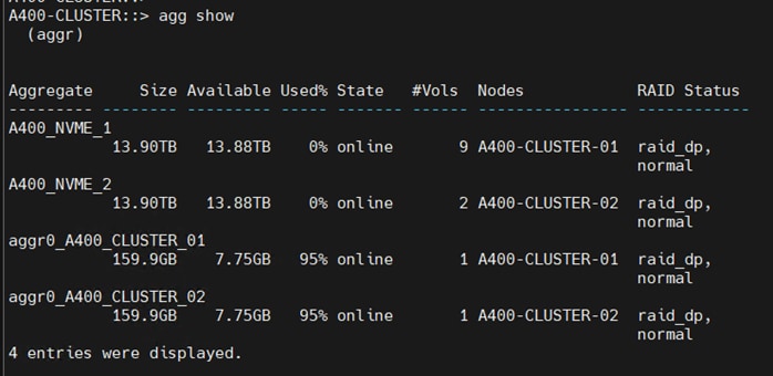
Step 2. The screenshot below shows the Storage VMs (formally known as vserver) configured as “HPC-SVM” for this solution:
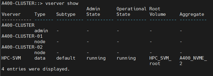
Step 3. The SVM named “HPC-SVM” was configured to carry all NFS traffic for this HPC Data Analytics solution.
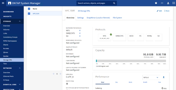
Step 4. Detailed configuration for HPC-SVM is shown below:
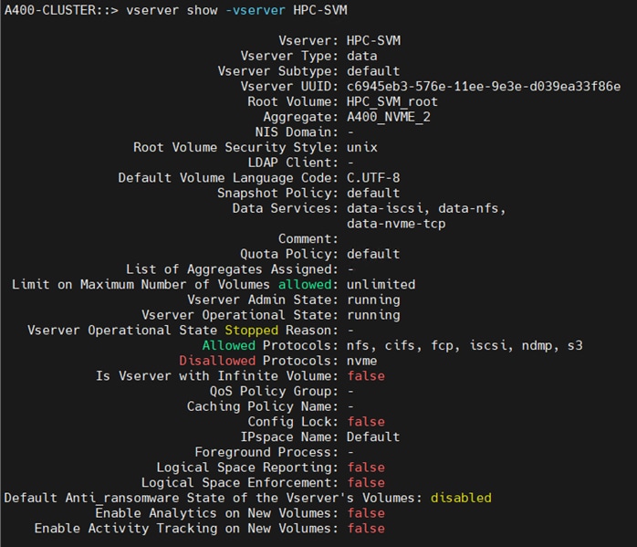
Step 5. The broadcast-domain was configured as “NFS-data” with MTU 9000 and assigned to default IPspace as shown below:
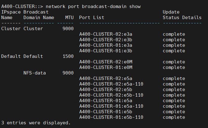
Step 6. The following screenshot shows the overview of the network configuration
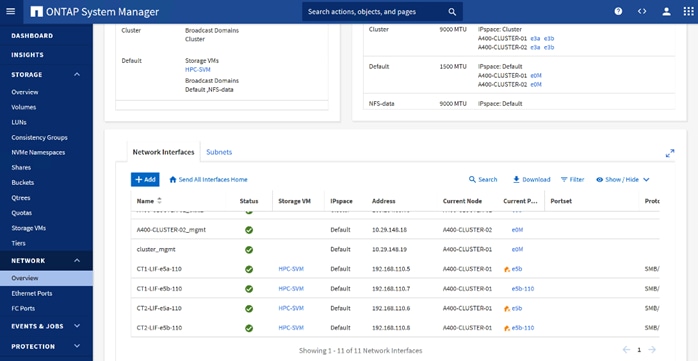
Step 7. The export policy “default” was configured and added rules with clients subnets for UNIX systems to allow the NFSv4 protocol as shown below:
Step 8. Enable Cisco Discovery protocol.
A400-CLUSTER::> node run -node * options cdpd.enable on
Step 9. Enable Link-Layer Discovery protocol on all ethernet ports:
A400-CLUSTER::> node run * options lldp.enable on
Appendix D – Monitor GPU Utilization
To monitor GPU utilization of our HPC cluster node while running different application; we created local Grafana dashboard for our solution test setup. This is for education purposes and recommended for lab/PoC only.
Prerequisites
1. Install and configure Grafana open-source server.
2. Verify Grafana server is running:
$ sudo systemctl status grafana-server
Install Prometheus and configure Prometheus to run as service
3. Verify that Prometheus is successfully installed using the below command:
$ prometheus –version
$ sudo systemctl start prometheus
sys
Step 1. Go to http://<Grafana_Server_IP_Address>:3000; Log into Grafana using default username and password admin/password.

Step 2. Change the password when prompted.
Step 3. Add Prometheus as data source.
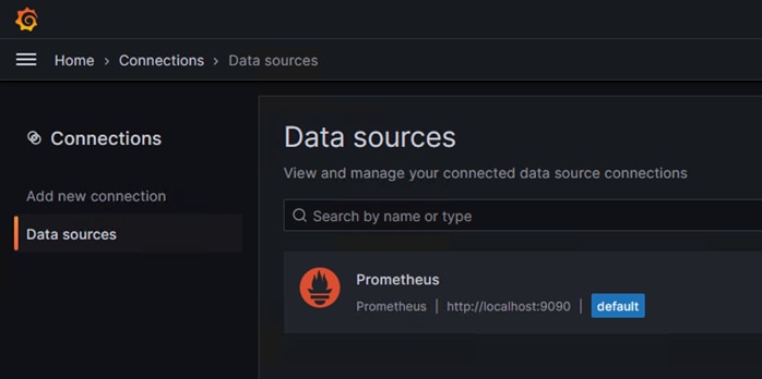
Step 4. Add a new dashboard in Grafana. Go to home > Dashboard > new > import.
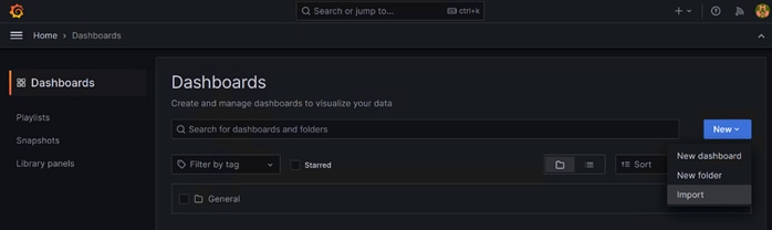
Step 5. Copy Grafana Dashboard ID “14574” for Nvidia GPU Metris: https://grafana.com/grafana/dashboards/14574-nvidia-gpu-metrics/
Step 6. Enter the Dashboard ID in Import via Grafana.com; click Load.
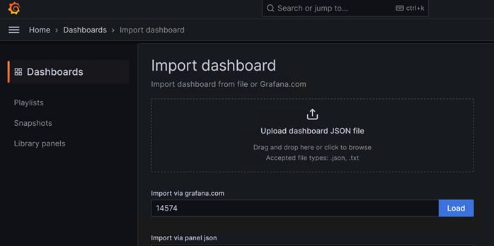
Step 7. Edit /etc/prometheus/prometheus.yml file as shown in the example below:
$ sudo vi /etc/prometheus/prometheus.yml
# my global config
global:
scrape_interval: 15s # Set the scrape interval to every 15 seconds. Default is every 1 minute.
evaluation_interval: 15s # Evaluate rules every 15 seconds. The default is every 1 minute.
# scrape_timeout is set to the global default (10s).
# Alertmanager configuration
alerting:
alertmanagers:
- static_configs:
- targets:
# - alertmanager:9093
# Load rules once and periodically evaluate them according to the global 'evaluation_interval'.
rule_files:
# - "first_rules.yml"
# - "second_rules.yml"
# A scrape configuration containing exactly one endpoint to scrape:
# Here it's Prometheus itself.
scrape_configs:
# The job name is added as a label `job=<job_name>` to any timeseries scraped from this config.
- job_name: "prometheus"
# metrics_path defaults to '/metrics'
# scheme defaults to 'http'.
static_configs:
- targets: ["10.29.148.171:9835"]
- targets: ["10.29.148.172:9835"]
- targets: ["10.29.148.173:9835"]
- targets: ["10.29.148.174:9835"]
- targets: ["10.29.148.175:9835"]
- targets: ["10.29.148.176:9835"]
- targets: ["10.29.148.177:9835"]
- targets: ["10.29.148.178:9835"]
Step 8. Download node exporter from GitHub:
https://github.com/utkuozdemir/nvidia_gpu_exporter/releases
Step 9. On each client node install nvidia-gpu-exporter; for example:
$ sudo dpkg -i nvidia-gpu-exporter_1.2.0_linux_amd64.deb
Step 10. Log into Grafana webUI; go to dashboard created for Grafana. From the drop-down list next to GPU allows to switch between different GPU monitoring.
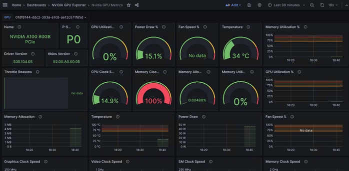
Appendix E– References used in this guide
Anycast RP Technology White Paper: https://www.cisco.com/c/en/us/td/docs/ios/solutions_docs/ip_multicast/White_papers/anycast.html
Campus Network for High Availability Design Guide, Tuning for Optimized Convergence: https://www.cisco.com/c/en/us/td/docs/solutions/Enterprise/Campus/HA_campus_DG/hacampusdg.html#wp1107578
Campus Network for High Availability Design Guide: https://www.cisco.com/c/en/us/td/docs/solutions/Enterprise/Campus/HA_campus_DG/hacampusdg.html
Appendix F – Recommended for you
Cisco Unified Computing System: https://www.cisco.com/site/us/en/products/computing/servers-unified-computing-systems/index.html
Cisco UCS 6536 Fabric Interconnects: https://www.cisco.com/c/en/us/products/collateral/servers-unified-computing/ucs6536-fabric-interconnect-ds.html
Cisco UCS X9508 Chassis: https://www.cisco.com/c/en/us/products/collateral/servers-unified-computing/ucs-x-series-modular-system/datasheet-c78-2472574.html
Cisco UCS X210c M7 Compute Node: https://www.cisco.com/c/en/us/products/collateral/servers-unified-computing/ucs-x-series-modular-system/ucs-x210c-m7-compute-node-ds.html
Cisco UCS X440p PCle Node: https://www.cisco.com/c/en/us/products/collateral/servers-unified-computing/ucs-x-series-modular-system/ucs-x440p-pcle-node-ds.html
Cisco UCS C240 M7 Rack Server: https://www.cisco.com/c/en/us/products/collateral/servers-unified-computing/ucs-c-series-rack-servers/ucs-c240-m7-rack-server-ds.html
Cisco UCS VIC 1500 Adapters: https://www.cisco.com/c/en/us/products/collateral/interfaces-modules/unified-computing-system-adapters/ucs-vic-15000-series-ds.html
Cisco Intersight Infrastructure Service: https://www.cisco.com/c/en/us/products/collateral/cloud-systems-management/intersight/intersight-ds.html
Cisco UCS Manager: https://www.cisco.com/c/en/us/products/servers-unified-computing/ucs-manager/index.html
NVIDIA GPU Cloud: https://www.nvidia.com/en-us/gpu-cloud/
NVIDIA AI Enterprise: https://www.nvidia.com/en-us/data-center/products/ai-enterprise/
NVIDIA HPC SDK: https://developer.nvidia.com/hpc-sdk
Cisco Nexus 9300-GX Series Switch: https://www.cisco.com/c/en/us/products/collateral/switches/nexus-9000-series-switches/nexus-9300-gx-series-switches-ds.html
Cisco Nexus 9336C-FX2 Switch: https://www.cisco.com/c/en/us/products/collateral/switches/nexus-9000-series-switches/datasheet-c78-742282.html
NetApp Data ONTAP: https://www.netapp.com/data-management/ontap-data-management-software/
NetApp AFF A400: https://www.netapp.com/data-storage/aff-a-series/aff-a400/
SpecHPC 2021 Benchmark Suite: https://www.spec.org/hpc2021/
For comments and suggestions about this guide and related guides, join the discussion on Cisco Community at https://cs.co/en-cvds.
CVD Program
ALL DESIGNS, SPECIFICATIONS, STATEMENTS, INFORMATION, AND RECOMMENDATIONS (COLLECTIVELY, "DESIGNS") IN THIS MANUAL ARE PRESENTED "AS IS," WITH ALL FAULTS. CISCO AND ITS SUPPLIERS DISCLAIM ALL WARRANTIES, INCLUDING, WITHOUT LIMITATION, THE WARRANTY OF MERCHANTABILITY, FITNESS FOR A PARTICULAR PURPOSE AND NONINFRINGEMENT OR ARISING FROM A COURSE OF DEALING, USAGE, OR TRADE PRACTICE. IN NO EVENT SHALL CISCO OR ITS SUPPLIERS BE LIABLE FOR ANY INDIRECT, SPECIAL, CONSEQUENTIAL, OR INCIDENTAL DAMAGES, INCLUDING, WITHOUT LIMITATION, LOST PROFITS OR LOSS OR DAMAGE TO DATA ARISING OUT OF THE USE OR INABILITY TO USE THE DESIGNS, EVEN IF CISCO OR ITS SUPPLIERS HAVE BEEN ADVISED OF THE POSSIBILITY OF SUCH DAMAGES.
THE DESIGNS ARE SUBJECT TO CHANGE WITHOUT NOTICE. USERS ARE SOLELY RESPONSIBLE FOR THEIR APPLICATION OF THE DESIGNS. THE DESIGNS DO NOT CONSTITUTE THE TECHNICAL OR OTHER PROFESSIONAL ADVICE OF CISCO, ITS SUPPLIERS OR PARTNERS. USERS SHOULD CONSULT THEIR OWN TECHNICAL ADVISORS BEFORE IMPLEMENTING THE DESIGNS. RESULTS MAY VARY DEPENDING ON FACTORS NOT TESTED BY CISCO.
CCDE, CCENT, Cisco Eos, Cisco Lumin, Cisco Nexus, Cisco StadiumVision, Cisco TelePresence, Cisco WebEx, the Cisco logo, DCE, and Welcome to the Human Network are trademarks; Changing the Way We Work, Live, Play, and Learn and Cisco Store are service marks; and Access Registrar, Aironet, AsyncOS, Bringing the Meeting To You, Catalyst, CCDA, CCDP, CCIE, CCIP, CCNA, CCNP, CCSP, CCVP, Cisco, the Cisco Certified Internetwork Expert logo, Cisco IOS, Cisco Press, Cisco Systems, Cisco Systems Capital, the Cisco Systems logo, Cisco Unified Computing System (Cisco UCS), Cisco UCS B-Series Blade Servers, Cisco UCS C-Series Rack Servers, Cisco UCS S-Series Storage Servers, Cisco UCS X-Series, Cisco UCS Manager, Cisco UCS Management Software, Cisco Unified Fabric, Cisco Application Centric Infrastructure, Cisco Nexus 9000 Series, Cisco Nexus 7000 Series. Cisco Prime Data Center Network Manager, Cisco NX-OS Software, Cisco MDS Series, Cisco Unity, Collaboration Without Limitation, EtherFast, EtherSwitch, Event Center, Fast Step, Follow Me Browsing, FormShare, GigaDrive, HomeLink, Internet Quotient, IOS, iPhone, iQuick Study, LightStream, Linksys, MediaTone, MeetingPlace, MeetingPlace Chime Sound, MGX, Networkers, Networking Academy, Network Registrar, PCNow, PIX, PowerPanels, ProConnect, ScriptShare, SenderBase, SMARTnet, Spectrum Expert, StackWise, The Fastest Way to Increase Your Internet Quotient, TransPath, WebEx, and the WebEx logo are registered trade-marks of Cisco Systems, Inc. and/or its affiliates in the United States and certain other countries. (LDW_P4)
All other trademarks mentioned in this document or website are the property of their respective owners. The use of the word partner does not imply a partnership relationship between Cisco and any other company. (0809R)