FlexPod Datacenter with Generative AI Inferencing
Available Languages
Bias-Free Language
The documentation set for this product strives to use bias-free language. For the purposes of this documentation set, bias-free is defined as language that does not imply discrimination based on age, disability, gender, racial identity, ethnic identity, sexual orientation, socioeconomic status, and intersectionality. Exceptions may be present in the documentation due to language that is hardcoded in the user interfaces of the product software, language used based on RFP documentation, or language that is used by a referenced third-party product. Learn more about how Cisco is using Inclusive Language.
- US/Canada 800-553-2447
- Worldwide Support Phone Numbers
- All Tools
 Feedback
 Feedback
Experience the power of UCS. Get free trials of cloud and computing products—plus special discounts.
Published: February 2024
![]()
In partnership with:

About the Cisco Validated Design Program
The Cisco Validated Design (CVD) program consists of systems and solutions designed, tested, and documented to facilitate faster, more reliable, and more predictable customer deployments. For more information, go to: http://www.cisco.com/go/designzone.
The FlexPod Datacenter solution is a validated approach for deploying Cisco and NetApp technologies and products to build shared private and public cloud infrastructure. Cisco and NetApp have partnered to deliver a series of FlexPod solutions that enable strategic data-center platforms. The success of the FlexPod solution is driven through its ability to evolve and incorporate both technology and product innovations in the areas of management, compute, storage, and networking. This document explains the design and deployment details of implementing a platform for Generative Artificial Intelligence (AI) Inferencing on the latest FlexPod Datacenter design with Cisco UCS M7 servers with NVIDIA GPUs managed from Cisco Intersight, end-to-end 100 Gbps networking with Cisco Nexus 9000 series switches, NetApp ONTAP 9.13.1 on the NetApp AFF A800 with NetApp Astra Trident for persistent storage, VMware vSphere 8.0, NVIDIA AI Enterprise (NVAIE) software, and the latest release of Red Hat Openshift Container Platform (OCP). This solution takes the latest FlexPod Datacenter with VMware validated design and layers on NVIDIA GPUs, NVAIE, OCP, and NetApp Astra Trident to produce a powerful platform for running Generative AI Inferencing software and models. Some of the key advantages of this Generative AI Inferencing on FlexPod Datacenter platform are:
● A platform built on a proven, reliable infrastructure: FlexPod Datacenter is an industry-leading Converged Infrastructure built on proven, high-quality components from Cisco and NetApp. The optimal FlexPod configuration is then documented and tested, using only firmware and software that have been tested for interoperability and published.
● High Performance: From the latest Cisco UCS M7 servers with the latest Intel CPUs and memory, to end-to-end 100 Gbps networking, to the latest version of NetApp ONTAP on NetApp’s high end storage controllers with NVMe drives, to later model NVIDIA GPUs, this platform is built to provide high performance with Generative AI Inferencing workloads.
● Sustainability: taking advantage of sustainability and power usage monitoring features of all the components of the stack, including GPUs, and utilizing the Cisco UCS X-Series advanced power and cooling policies.
● Simpler and programmable infrastructure: infrastructure as code delivered using Ansible.
● Built for investment protections: design ready for future technologies such as newer or higher performing GPUs.
In addition to the compute-specific hardware and software innovations, the integration of the Cisco Intersight cloud platform with VMware vCenter, NetApp Active IQ Unified Manager, and Cisco Nexus switches delivers monitoring, and orchestration capabilities for different layers (virtualization, storage, and networking) of the FlexPod infrastructure. The modular nature of the Cisco Intersight platform also provides an easy upgrade path to additional services as they become available.
For information about the FlexPod design and deployment details, including the configuration of various elements of design and associated best practices, refer to Cisco Validated Designs for FlexPod, here: https://www.cisco.com/c/en/us/solutions/design-zone/data-center-design-guides/flexpod-design-guides.html.
Solution Overview and Design
This chapter contains the following:
● Audience
In simpler terms, think of it as the moment of truth for an AI model. It’s when the model takes real-time data, compares it with what it learned during training, and produces an actionable result. For example, it can transcribe speech, identify spam emails, or summarize lengthy documents. The goal is to apply what the model learned and put it into practice.
However, there’s an interesting twist: while training an AI model can be expensive, inferencing is where the real costs lie. Running an AI model for inference consumes energy, dollars, and contributes to carbon emissions. In fact, up to 90% of an AI model’s life is spent in inference mode, making it a critical area for optimization. Tech companies are actively working on speeding up inferencing to improve user experience and reduce operational costs.
The intended audience of this document includes but is not limited to IT architects, sales engineers, field consultants, professional services, IT managers, partner engineering, and customers who want to take advantage of an infrastructure built to deliver IT efficiency and enable IT innovation.
This document provides design and deployment guidance around implementing FlexPod Datacenter with Red Hat Openshift Container Platform (OCP), NVIDIA GPUs, and NVIDIA AI Enterprise (NVAIE) software as a platform for running Generative AI Inferencing. This document provides best practice configuration of both FlexPod and the additional components to support Generative AI Inferencing.
The following design elements are added to FlexPod Datacenter to build a platform for Generative AI Inferencing:
● Specifying how to add a tenant to FlexPod Datacenter to house the components for Generative AI Inferencing
● NetApp ONTAP 9.13.1
● Layering of OCP on top of a VMware vSphere based FlexPod
● Use of NetApp Astra Trident with OCP to provide persistent storage to containers
● Addition of NVIDIA GPUs to Cisco UCS Servers
● Use of NVAIE GPU and vGPU drivers and software with both VMware vSphere and OCP
● Use of Cisco Intersight and other tools to monitor GPU and server energy consumption, temperatures, and utilization
● Demonstration of how to deploy and monitor performance of various Generative AI Inferencing servers and models
The FlexPod Datacenter solution as a platform for Generative AI Inferencing offers the following key benefits:
● The ability to implement readily available AI Inferencing models quickly and easily on a powerful platform with high-speed persistent storage, reducing customer spending on cloud.
● Save time and reduce errors with deployment ready Ansible playbooks for the base FlexPod setup and for FlexPod AI additions in the future.
● Simplified cloud-based management of solution components
● Hybrid-cloud-ready, policy-driven modular design
● Highly available and scalable platform with flexible architecture that supports various deployment models
● Cooperative support model and Cisco Solution Support
● Easy to deploy, consume, and manage architecture, which saves time and resources required to research, procure, and integrate off-the-shelf components
● Support for component monitoring, solution automation and orchestration, and workload optimization
Like all other FlexPod solution designs, FlexPod Datacenter with Generative AI Inferencing is configurable according to demand and usage. You can purchase exactly the infrastructure you need for your current application requirements and can then scale-up by adding more resources to the FlexPod system or scale-out by adding more FlexPod instances. Since many Generative AI Inferencing applications are containerized, use of OCP provides a single platform for hosting these applications and the corresponding AI models.
This chapter contains the following:
● Cisco Unified Computing System Additions
● Cisco Nexus Switching Fabric
● Red Hat OCP on VMware vSphere
The IP-based end-to-end 100G FlexPod Datacenter was used as the basis for this solution, and is specified here: https://www.cisco.com/c/en/us/td/docs/unified_computing/ucs/UCS_CVDs/flexpod_m7_imm_vmware_design.html. This document will not repeat information from that document but will instead present what was updated or added for each component. The base FlexPod used in this validation used the following specific components:
● Cisco UCS X9508 Chassis with Cisco UCSX-I-9108-100G Intelligent Fabric Modules, Cisco UCS 9416 X-Fabric Modules and Cisco UCS X210c M7 and X210c M6 Compute Nodes
● Fifth-generation Cisco UCS 6536 Fabric Interconnects to support 10/25/40/100GbE connectivity from various components
● Cisco UCS C220 M7 and C240 M7 Rack Mount Servers attached directly to the Fabric Interconnects
● High-speed Cisco NX-OS-based Cisco Nexus 93600CD-GX switching designed to support up to 400GE connectivity
● NetApp AFF A800 end-to-end NVMe storage with up to 100GE connectivity
● NVIDIA A100-80 GPUs in Cisco UCS X440p PCIe Nodes connected to Cisco UCS X210c M7 Servers by Cisco UCS X-Fabric
The NVIDIA A100-80 PCIe GPU (UCSX-GPU-A100-80-D) was specifically used for this validation. However, any NVIDIA GPU supported with either the Cisco UCS X210C M7 or UCS C240/C220 M7 servers can be used in this platform. For information on the A100-80, see https://www.nvidia.com/en-us/data-center/a100/.
This validation used the A100-80 in two ways:
The first way the NVIDIA GPU was used was in NVIDIA Virtual Compute Server (vCS) mode, which took the physical GPU, loaded the NVAIE driver in VMware ESXi, and broke the physical GPU into multiple virtual GPUs (vGPUs) that could be assigned to Red Hat OCP worker VMs with VMware PCI passthrough. The NVAIE driver creates multiple sized vGPU profiles that divide up the 80GB of GPU frame buffer provided by the A100-80 and are used for assignment. In vCS mode, GPU frame buffer memory is divided up, but the entire GPU compute resources are shared by all the vGPUs. vCS mode is supported in all NVIDIA GPUs supported in Cisco UCS and the functionality used in this CVD can be applied to all supported NVIDIA GPUs. NVIDIA Multi-Instance GPU (MIG) described here: https://docs.nvidia.com/datacenter/tesla/mig-user-guide/index.html is another option that securely partitions a GPU into up to seven separate GPU Instances each with their own isolated memory and compute resources. This method of assigning vGPUs using profiles is useful when multiple vGPUs can be used to run a larger number of smaller AI models or replicas of the same smaller AI model at the same time.
Note: MIG is only supported in a subset of NVIDIA GPUs and was not validated in this CVD.
The second way the NVIDIA GPU was used was to not load the VMware NVAIE drivers and to assign the full physical GPU to the Red Hat OCP worker VM with VMware PCI passthrough. This method required a different GPU driver to be installed in OCP instead of the vGPU driver. This method of assigning the entire physical GPU to an OCP worker VM allows larger AI models, such as Llama 2 70B, to be run.
Cisco Unified Computing System Additions
To support Generative AI Inferencing, NVIDIA GPUs were added to Cisco UCS X210c M7 servers. The Cisco UCS X210c M7 supports up to two NVIDIA T4 GPUs in the front mezzanine GPU adapter. The Cisco UCS X210c M7 supports additional GPUs when used with Cisco UCS X-Fabric and the X440p PCIe Node.
Cisco UCS X-Fabric
The first generation of X-Fabric Technology, Cisco UCS 9416 X-Fabric Modules connect Cisco UCS X210c and X410c server nodes to Cisco UCS X440p PCIe Nodes. Cisco UCS X-Fabric also requires a Cisco UCS PCI Mezz Card (UCSX-V4-PCIME-D) or a mezzanine Cisco VIC card and Cisco VIC bridge card in the mezzanine slot to enable connectivity to the X440p PCIe node described below.
Cisco UCS X440p PCIe Node
The Cisco UCS X440p PCIe Node is the first PCIe resource node to integrate into the Cisco UCS X-Series Modular System. The Cisco UCS X9508 Chassis has eight node slots, up to four of which can be X440p PCIe nodes when paired with a Cisco UCS X210c M7 or M6 Compute Node. The Cisco UCS X440p PCIe Node supports two x16 full-height, full-length dual slot PCIe cards, or four x8 half-height, half-length single slot PCIe cards and requires both Cisco UCS 9416 X-Fabric modules for PCIe connectivity. This provides up to 16 GPUs per chassis to accelerate your applications with the Cisco UCS X440p Nodes. If your application needs even more GPU acceleration, up to two additional GPUs can be added on each Cisco UCS X210c compute node as stated above. For additional information on the Cisco UCS X440p PCIe Node, including the latest updates, see the datasheet here: https://www.cisco.com/c/en/us/products/collateral/servers-unified-computing/ucs-x-series-modular-system/ucs-x440p-pcle-node-ds.html.
Cisco UCS X440p supports the following GPU options:
● NVIDIA H100 Tensor Core GPU
● NVIDIA L40 GPU
● NVIDIA L4 Tensor Core GPU
● NVIDIA A100 Tensor Core GPU
● NVIDIA A16 GPU
● NVIDIA A40 GPU
● Intel Data Center GPU Flex 140
● Intel Data Center GPU Flex 170
Note: Intel Data Center GPUs, although supported with the X440p, would require a different driver setup and process, and were not validated in this CVD.
Figure 1. Cisco UCS X440p PCIe Node
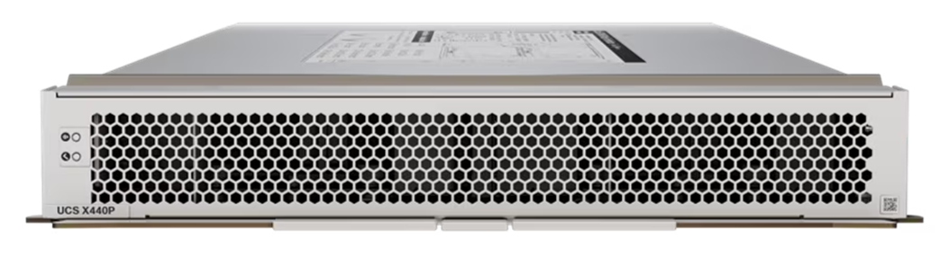
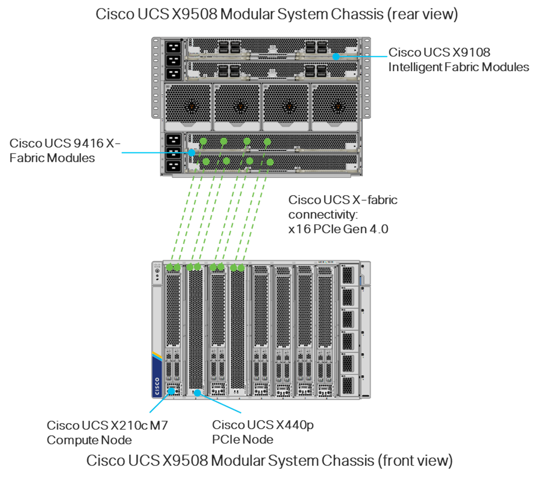
Figure 2 shows the typical setup of Cisco UCS X440p modules paired with Cisco UCS X210c M6 and M7 servers. The server is usually placed in an odd-numbered slot and the Cisco UCS X440p is placed next to it in an even-numbered slot. For current information on supported GPUs associated requirements, see the Cisco UCS X210c M7 spec sheet here: https://www.cisco.com/c/dam/en/us/products/collateral/servers-unified-computing/ucs-x-series-modular-system/x210cm7-specsheet.pdf and the Cisco UCS X410c M7 spec sheet here: https://www.cisco.com/c/dam/en/us/products/collateral/servers-unified-computing/ucs-x-series-modular-system/x410cm7-specsheet.pdf.
Note: In the diagram, even though X-fabric connectivity is shown on four server slots, this connectivity extends across all eight server slots.
Figure 2. Cisco UCS X-Fabric Connectivity
Cisco UCS C220 M7 and C240 M7 NVIDIA GPU Options
The Cisco UCS C220 M7 can support up to 3 NVIDIA L4 GPUs or up to 3 Intel Flex 140 GPUs (Spec Sheet: https://www.cisco.com/c/dam/en/us/products/collateral/servers-unified-computing/ucs-c-series-rack-servers/c220m7-sff-specsheet.pdf). The Cisco UCS C240 M7 can support a wide range of GPUs including up to 3 NVIDIA A100-80 GPUs. For detailed information on the Cisco UCS C240 M7, see the spec sheet here: https://www.cisco.com/c/dam/en/us/products/collateral/servers-unified-computing/ucs-c-series-rack-servers/c240m7-sff-specsheet.pdf. Cisco UCS C-Series servers were not validated with GPUs in this CVD, but they are supported. Go to: https://www.cisco.com/c/en/us/td/docs/unified_computing/ucs/UCS_CVDs/flexpod_gpu_aiml.html for an example of Cisco UCS C-Series servers being validated with NVIDIA GPUs.
Cisco Nexus 93600CD-GX
Based on Cisco Cloud Scale technology, the Cisco Nexus 9300-GX switches are the next generation of fixed Cisco Nexus 9000 Series Switches capable of supporting 400 Gigabit Ethernet (GE). With the increase in use cases for applications requiring Artificial Intelligence (AI) and Machine Learning (ML), the platform addresses the need for high-performance, power-efficient, compact switches in the networking infrastructure. These switches are designed to support 100G and 400G fabrics for mobile service provider environments, including the network edge, 5G, IoT, Professional Media Networking platform (PMN), and Network Functions Virtualization (NFV).
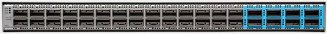
The Cisco Nexus 93600CD-GX Switch (Figure 3) is a 1RU switch that supports 12 Tbps of bandwidth and 4.0 bpps across 28 fixed 40/100G QSFP-28 ports and 8 fixed 10/25/40/50/100/200/400G QSFP-DD ports.
Cisco provides two modes of operation for Cisco Nexus 9000 Series Switches. Organizations can deploy Cisco Application Centric Infrastructure (Cisco ACI) or Cisco NX-OS mode.
Figure 3. Cisco UCS Nexus 93600CD-GX Switch
For more details, go to: https://www.cisco.com/c/en/us/products/collateral/switches/nexus-9000-series-switches/nexus-9300-gx-series-switches-ds.html.
The switching infrastructure in this document utilized the NX-OS switching mode. The switching infrastructure in future iterations of this document will follow the Cisco Data Center Networking Blueprint for AI/ML Applications and will utilize a spine-leaf architecture and VXLAN EVPN Network.
NetApp AFF A800 is mentioned in this document. Detailed information about NetApp AFF A-Series Storage is specified here: https://www.cisco.com/c/en/us/td/docs/unified_computing/ucs/UCS_CVDs/flexpod_m7_imm_vmware_design.html#NetApp_AFF_A_Series_Storage
Detailed information about NetApp AFF C-Series Storage is specified here: https://www.cisco.com/c/en/us/td/docs/unified_computing/ucs/UCS_CVDs/flexpod_m7_imm_vmware_design.html#NetAppAFFCSeriesStorage
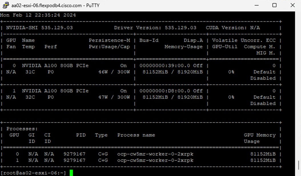
In order to implement NVIDIA GPU vCS mode, a pair of NVAIE vibs or drivers were installed on each VMware ESXi 8.0 host that had GPUs. After installing these drivers and setting the Graphics Device Settings to Shared Direct Vendor shared passthrough graphics, vGPUs could then be assigned to VMs, including Red Hat OCP worker VMs after OCP installation. NVAIE also installs the nvidia-smi application on the ESXi host, providing a tool to monitor and manage installed NVIDIA GPUs. On VMware ESXi, this tool provides physical GPU statistics such as GPU temperature, power consumption, memory usage of assigned vGPUs, and GPU utilization in addition to how much vGPU memory is assigned to worker VMs.
Figure 4. nvidia-smi Tool on VMware ESXi
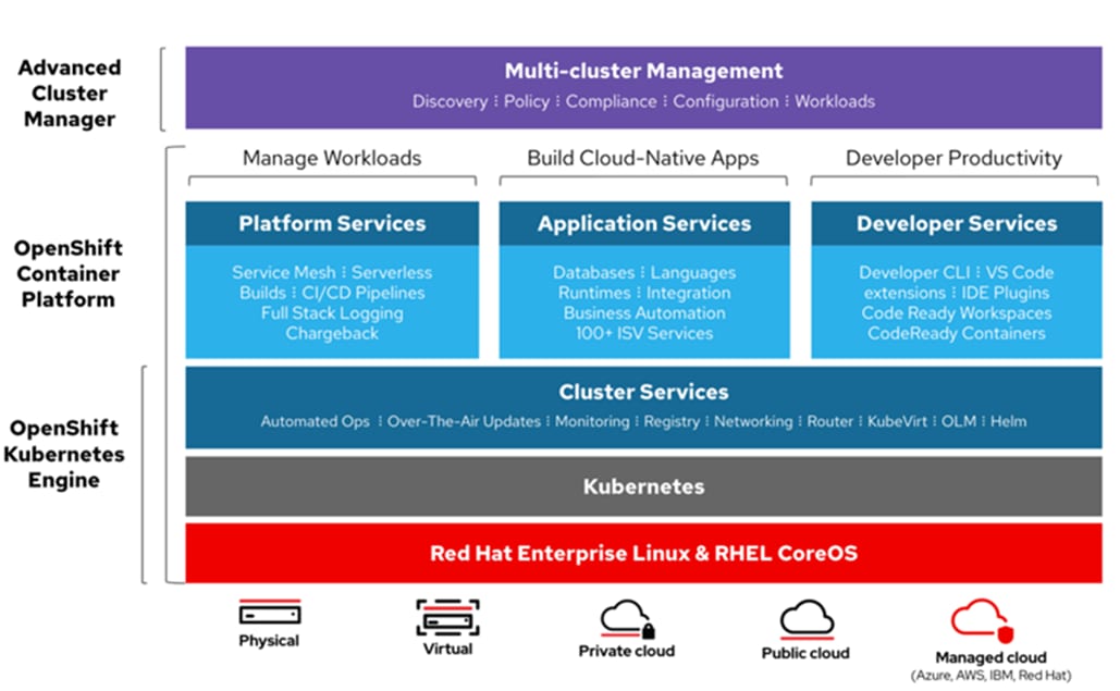
The RedHat OpenShift Container Platform (OCP) is a container application platform that brings together CRI-0 and Kubernetes and provides an API and web interface to manage these services. CRI-O is an implementation of the Kubernetes CRI (Container Runtime Interface) to enable using Open Container Initiative (OCI) compatible runtimes. It is a lightweight alternative to using Docker as the runtime for Kubernetes.
OCP allows you to create and manage containers. Containers are standalone processes that run within their own environment, independent of operating system and the underlying infrastructure. OCP helps developing, deploying, and managing container-based applications. It provides a self-service platform to create, modify, and deploy applications on demand, thus enabling faster development and release life cycles. OCP has a microservices-based architecture of smaller, decoupled units that work together. It runs on top of a Kubernetes cluster, with data about the objects stored in etcd, a reliable clustered key-value store.
Figure 5. Openshift Container Platform Overview
Kubernetes Infrastructure
Within OpenShift Container Platform, Kubernetes manages containerized applications across a set of CRI-O runtime hosts and provides mechanisms for deployment, maintenance, and application-scaling. The CRI-O service packages, instantiates, and runs containerized applications.
A Kubernetes cluster consists of one or more masters and a set of worker nodes. This solution design includes HA functionality at the VMware level as well as the OCP software level. A Kubernetes cluster is designed to run in HA mode with 3 master nodes and a minimum of 2 worker nodes to help ensure that the cluster has no single point of failure.
Red Hat Core OS
OpenShift Container Platform uses Red Hat Enterprise Linux CoreOS (RHCOS), a container-oriented operating system that combines some of the best features and functions of the CoreOS and Red Hat Atomic Host operating systems. RHCOS is specifically designed for running containerized applications from OpenShift Container Platform and works with new tools to provide fast installation, Operator-based management, and simplified upgrades.
RHCOS includes the following:
● Ignition, which OpenShift Container Platform uses as a first boot system configuration for initially bringing up and configuring machines.
● CRI-O, a Kubernetes native container runtime implementation that integrates closely with the operating system to deliver an efficient and optimized Kubernetes experience. CRI-O provides facilities for running, stopping, and restarting containers. It fully replaces the Docker Container Engine, which was used in OpenShift Container Platform 3.
● Kubelet, the primary node agent for Kubernetes that is responsible for launching and monitoring containers.
In this CVD OCP was installed on VMware using the Red Hat OCP Installer-Provisioned-Infrastructure (IPI) installer. The IPI installer connects to VMware vCenter, creates the needed master and worker VMs, and installs and configures RHCOS.
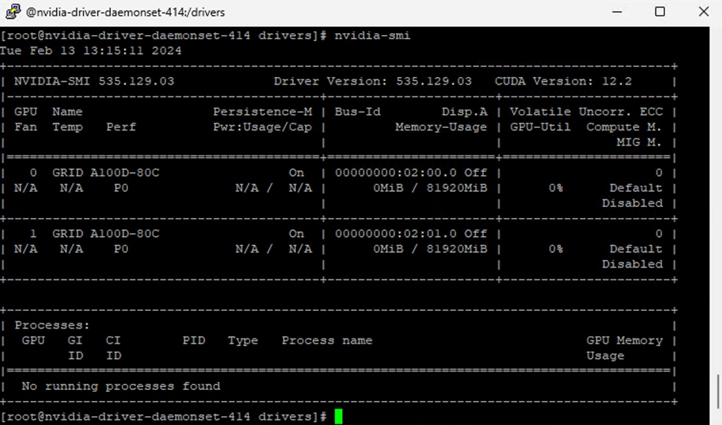
Once OCP is installed on top of VMware vSphere with the NVAIE drivers installed and vGPUs are added to the OCP worker VMs, the NVIDIA GPU Operator can then be installed in OCP. The NVIDIA GPU operator provides access to the Openshift vGPU driver which is used in the containers that the vGPU(s) are attached. The NVIDIA GPU operator also pulls vGPU licenses from an NVIDIA license server that can be installed on premis or in the NVIDIA cloud. Proper licensing is required for the vGPUs to perform. A number of pods that support NVIDIA vGPU operation and monitoring are also created in each worker VM that has vGPUs assigned. The nvidia-smi tool, with the vGPU view, is also available in the nvidia-driver-daemonset pod in the nvidia-gpu-operator project. This tool does not report power or temperature data, but does show vGPU memory usage, GPU utilization (since GPU compute resources are shared with vCS), and any pods or containers that are attached to the vGPU. In the figure below, two vGPUs are assigned to the OCP worker VM with the profile that provides 80G of memory to each vGPU.
Figure 6. nvidia-smi from the vGPU
NetApp Astra Trident
Astra Trident is an open-source, fully supported storage orchestrator for containers created by NetApp. It has been designed from the ground up to help you meet your containerized applications persistence demands using industry-standard interfaces, such as the Container Storage Interface (CSI). With Astra Trident, microservices and containerized applications can take advantage of enterprise-class storage services provided by the full NetApp portfolio of storage systems. In a FlexPod environment, Astra Trident is utilized to allow end users to dynamically provision and manage persistent volumes for containers backed by FlexVols and LUNs hosted on ONTAP-based products such as NetApp AFF and FAS systems.
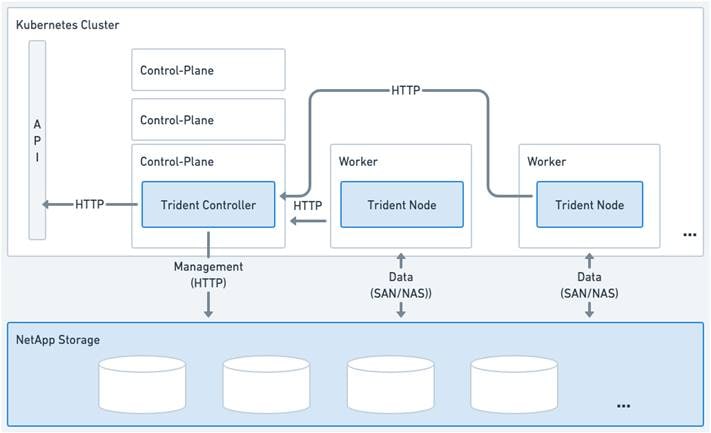
Astra Trident deploys as a single Trident Controller Pod and one or more Trident Node Pods on the Kubernetes cluster and uses standard Kubernetes CSI Sidecar Containers to simplify the deployment of CSI plugins. Kubernetes CSI Sidecar Containers are maintained by the Kubernetes Storage community.
Kubernetes node selectors and tolerations and taints are used to constrain a pod to run on a specific or preferred node. You can configure node selectors and tolerations for controller and node pods during Astra Trident installation.
● The controller plugin handles volume provisioning and management, such as snapshots and resizing.
● The node plugin handles attaching the storage to the node.
Figure 7. Astra Trident deployed on the Kubernetes cluster
NetApp DataOps Toolkit
The NetApp DataOps Toolkit is a Python library that makes it easy for developers, data scientists, and data engineers to perform numerous data management tasks. These tasks include provisioning a new data volume or development workspace, cloning a data volume or development workspace almost instantaneously, and creating a NetApp Snapshot copy of a data volume or development workspace for traceability and baselining. This Python library can function as either a command-line utility or a library of functions that can be imported into any Python program or Jupyter Notebook.
The DataOps Toolkit supports Linux and macOS hosts. The toolkit must be used in conjunction with a NetApp data storage system or service. It simplifies various data management tasks that are executed by the data storage system or service. To facilitate this simplification, the toolkit communicates with the data storage system or service through an API.
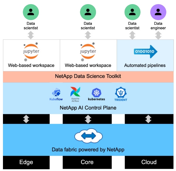
The NetApp DataOps Toolkit for Kubernetes abstracts storage resources and Kubernetes workloads up to the data-science workspace level. These capabilities are packaged in a simple, easy-to-use interface that is designed for data scientists and data engineers. Using the familiar form of a Python program, the Toolkit enables data scientists and engineers to provision and destroy JupyterLab workspaces in just seconds. These workspaces can contain terabytes, or even petabytes, of storage capacity, enabling data scientists to store all their training datasets directly in their project workspaces. Gone are the days of separately managing workspaces and data volumes.
Figure 8. NetApp Data Science Toolkit
Various Generative AI Inferencing Models were run and benchmarked as part of this validation. One method for Generative AI Inferencing is to load an inferencing server with an AI model. The inferencing server then has a listener that waits for inferencing requests and responds to the requests. A second method is to load the model into the GPU(s), run the inferencing request(s), provide the response(s), and unload the model. In this validation, NetApp Astra Trident-provided persistent storage was used to store the AI models, preventing the models from being downloaded each time a pod was created or re-created. For this validation, AI software and models were obtained from NVAIE, Hugging Face, Github, and other sources. NVAIE provides a wide range of inferencing servers, AI frameworks, and AI models for NVIDIA GPUs.
NVIDIA NeMo Framework Inference
NVIDIA NeMo™ Framework is an end-to-end, cloud-native enterprise framework to build, customize, and deploy generative AI models with billions of parameters. The NeMo Framework Inferencing container utilizes the NVIDIA Triton Inferencing Server to serve NeMo formatted AI inferencing models. The version of the NeMo Framework Inferencing container validated in this CVD has been deprecated by NVIDIA. The container referenced above was pulled from NVIDIA unmodified and placed on quay.io to allow the testing in this CVD to be replicated.
Text Generation Inference (TGI)
TGI is a toolkit for deploying and serving Large Language Models (LLMs). The TGI container is downloaded from Hugging Face and contains all of the necessary software to support usage of NVIDIA GPUs. TGI supports a wide range of AI models, and fourteen different AI Inferencing models were run as part of the validation.
PyTorch
PyTorch is an optimized tensor library for deep learning using GPUs and CPUs. The PyTorch container is downloaded from the NVIDIA NGC Catalog and is NVAIE supported. When running AI Inferencing models with PyTorch, the model is loaded into the GPU, inferencing is run, response is provided, and the model is unloaded.
Table 1. AI Inferencing Models Run
| Inferencing Serving |
Model |
Base Container Used for Inferencing |
| NeMo Framework Inference |
Nemo GPT 2B |
quay.io/jogeorg2/nemofw-inference:23.10_fix_v2 |
| Nemotron 3 8B QA |
||
| Llama-2-7B-Chat |
||
| Llama-2-13B-Chat |
||
| Llama-2-70B-Chat |
||
| Llama-2-SteerLM-Chat |
||
| TGI |
BLOOM 7B |
ghcr.io/huggingface/text-generation-inference |
| Google FLAN-T5 XL 2.85B |
||
| Google FLAN-T5 XXL 11.3B |
||
| GALACTICA 30B |
||
| GPT-NeoX-20B |
||
| OPT- 2.7B |
||
| MPT-30B |
||
| Falcon-40B |
||
| Mistral-7B-v0.1 |
||
| Code Llama 34B-Base |
||
| Code Llama 70B-Base |
||
| Llama-2-70B-Chat-HF |
||
| Defog SQLCoder-15B |
||
| Defog SQLCoder-34B |
||
| PyTorch |
Llama-2-7B-Chat |
nvcr.io/nvidia/pytorch:23.10-py3 |
| Llama-2-13B-Chat |
||
| resnet34* |
||
| Stable Diffusion 1.4* |
||
| Stable Diffusion 1.5* |
||
| Stable Diffusion 2* |
||
| Stable Diffusion 2.1* |
||
| Stable Diffusion XL* |
||
| Openjourney* |
||
| Dreamlike Diffusion 1.0* |
||
| Hotshot-XL* |
*Run using NetApp DataOps Toolkit with a Jupyter Notebook.
In this solution, GPUs were monitored in three ways:
nvidia-smi
The first was with the nvidia-smi tool that is installed as part of NVAIE and is mentioned above. From a monitoring perspective, the main screen of the tool can be monitored constantly by using the loop command line parameter or by using the Linux watch command. The tool also has numerous command line options to generate data about the GPU and can produce CSV files with data at specified intervals for graphing GPU data. The important thing to remember with nvidia-smi in this solution is where it is being run from. If it is run from VMware ESXi, it returns physical GPU statistics and data. If it is run from a container or pod in OCP, it returns vGPU statistics and data.
VMware vCenter GPU Statistics
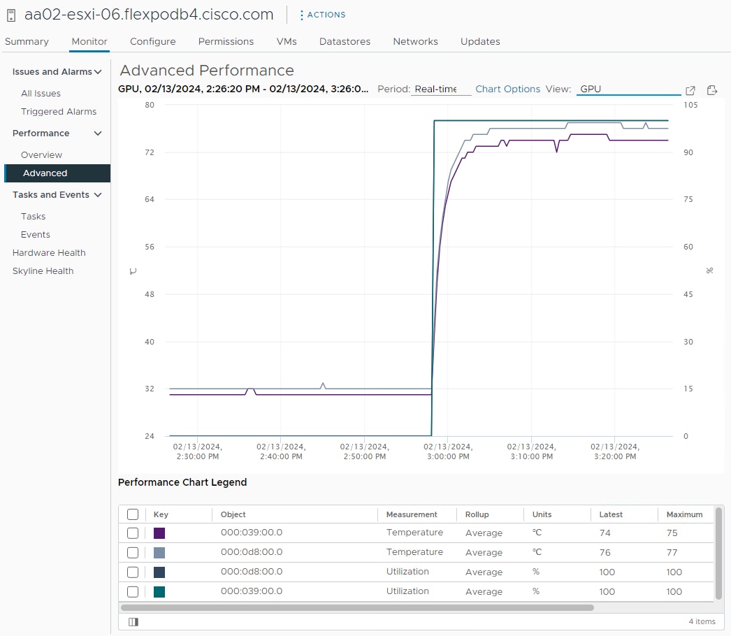
In addition to nvidia-smi, the NVAIE vibs that are installed on VMware ESXi allow VMware vCenter to collect and show real time physical GPU data. GPU memory usage, memory used, temperature, and utilization are collected and up to two of these items can be charted and displayed in VMware vCenter. The figure below shows an example while running GPU Burn.
Figure 9. VMware vCenter GPU Statistics While Running GPU Burn
OCP Console NVIDIA DCGM Exporter Dashboard
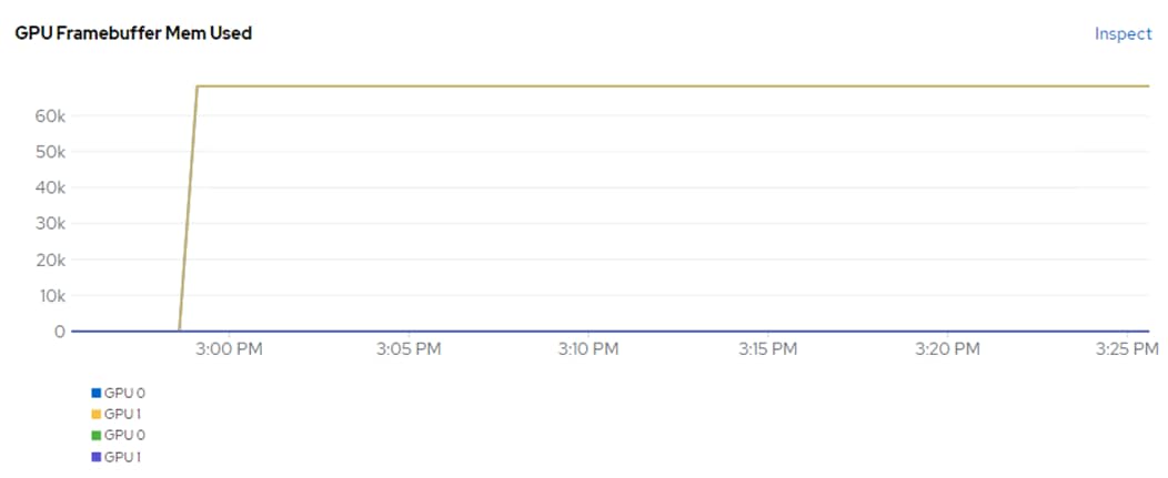
The NVIDIA GPU Operator exposes vGPU telemetry for Prometheus by using the NVIDIA DCGM Exporter. These metrics can be visualized using a monitoring dashboard based on Grafana. The NVIDIA DCGM Exporter Grafana Dashboard can be installed in OCP and viewed in the OCP console. Figure 10 shows an example while running GPU Burn.
Figure 10. NVIDIA DCGM Exporter Dashboard While Running GPU Burn
Cisco Intersight
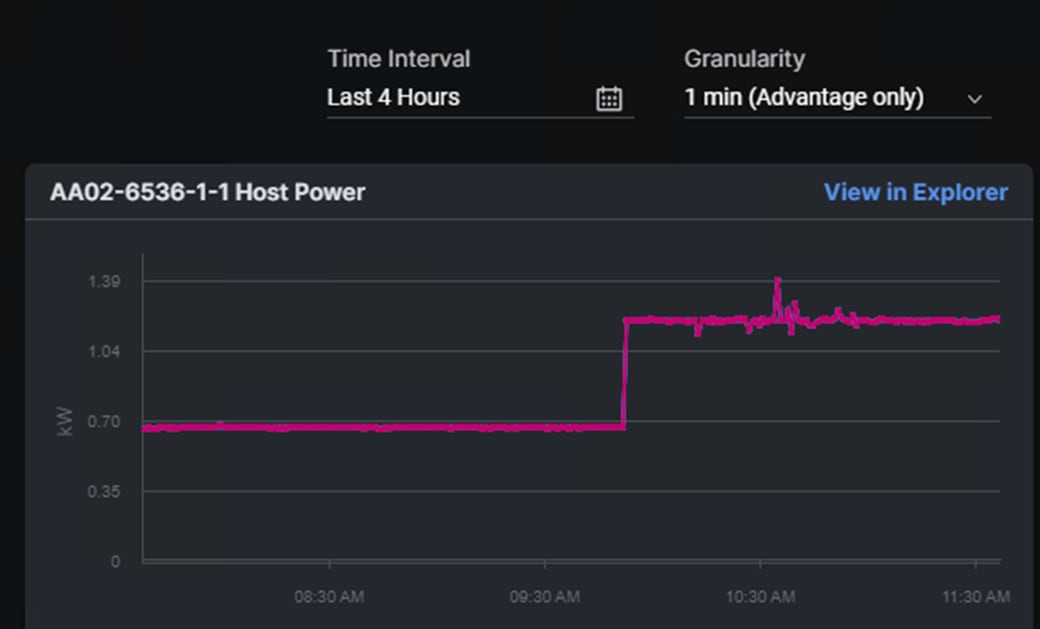
In Cisco Intersight, power consumption of GPUs installed in a Cisco UCS X440p and attached to an X210C M7 server using Cisco UCS X-Fabric is added to the server’s power consumption and shown in the server Metrics screen. In Figure 11, the Cisco UCS X210C M7 was using around 600W before GPU Burn was started. Each of the 2 NIVIDIA A100-80 GPUs attached to this server have a maximum usage of 300W. GPU Burn adds 600W of power consumption to the server from the GPUs to get to a server power consumption of around 1200W.
Figure 11. Cisco UCS Server Power Usage While Running GPU Burn
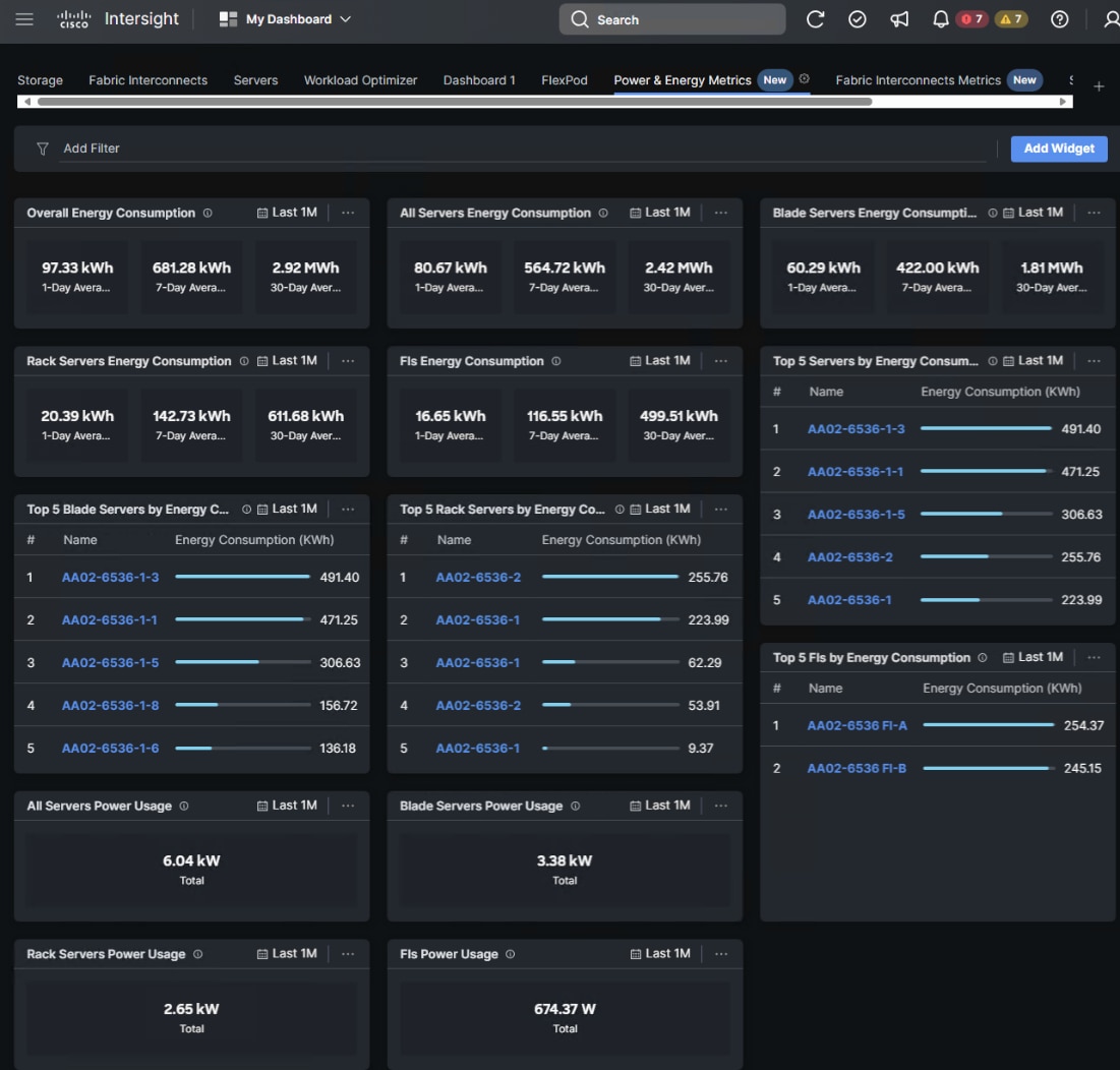
Cisco Intersight has also recently added a Power & Energy Metrics Dashboard under My Dashboard. This dashboard shows summary power and energy metrics for all servers in the Intersight Account.
Figure 12. Cisco Intersight Power and Energy Metrics Dashboard
VMware vSphere
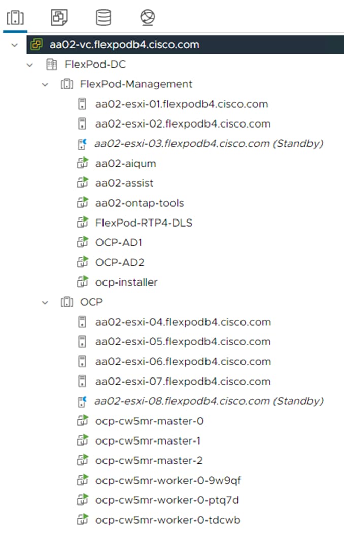
In VMware vSphere, Distributed Power Management (DPM) was tested as part of this validation. The FlexPod-Management cluster in this validation consisted of 7 VMs running on a cluster of 3 VMware ESXi hosts and the OCP cluster consisted of 6 VMs running on a cluster of 5 VMware ESXi hosts. DPM uses IPMI over LAN to power on hosts that have been put into Standby mode when necessary. DPM was enabled in a manual automation mode for each cluster, and it was disabled with an override for hosts with GPUs. Then two hosts (one in each cluster) were suspended (powered off), saving energy consumption.
Solution Design
This chapter contains the following:
● FlexPod Multi-Tenant Configuration
The FlexPod Datacenter with Cisco UCS and Cisco Intersight meets the following general design requirements:
● Resilient design across all layers of the infrastructure with no single point of failure
● Scalable design with the flexibility to add compute capacity, storage, or network bandwidth as needed
● Modular design that can be replicated to expand and grow as the needs of the business grow
● Flexible design that can support different models of various components with ease
● Simplified design with ability to integrate and automate with external automation tools
● Cloud-enabled design which can be configured, managed, and orchestrated from the cloud using GUI or APIs
To deliver a solution which meets all these design requirements, various solution components are connected and configured as covered in the upcoming sections.
The FlexPod Datacenter solution with Cisco UCS IMM M7, VMware 8.0, and NetApp ONTAP 9.13.1 is built using the following hardware components:
● Cisco UCS X9508 Chassis with Cisco UCSX-I-9108-100G intelligent fabric modules (IFMs), up to eight Cisco UCS X210C M7 Compute Nodes with 4th Generation Intel Xeon Scalable CPUs, and up to four Cisco UCS X440p PCIe Nodes each with up to two NVIDIA A100-80 GPUs (each X440p would go in place of an X210c)
● Fourth-generation Cisco UCS 6536 Fabric Interconnects to support 100GbE and 25GbE connectivity from various components
● Cisco UCS C220 M7 and C240 M7 rack mount servers with 4th Generation Intel Xeon Scalable CPUs
● High-speed Cisco NX-OS-based Nexus 93600CD-GX switching design to support 100GE and 400GE connectivity
● NetApp AFF A800 end-to-end NVMe storage with 25G or 100G Ethernet
The software components of this solution consist of:
● Cisco Intersight to deploy, maintain, and support the Cisco UCS server components
● Cisco Intersight SaaS platform to maintain and support the FlexPod components
● Cisco Intersight Assist Virtual Appliance to help connect NetApp ONTAP, VMware vCenter, and Cisco Nexus switches with Cisco Intersight
● NetApp Active IQ Unified Manager to monitor and manage the storage and for NetApp ONTAP integration with Cisco Intersight
● VMware vCenter to set up and manage the virtual infrastructure as well as Cisco Intersight integration
● Red Hat OCP to manage a Kubernetes containerized environment
● NVAIE at both the VMware ESXi and Red Hat OCP layers to manage GPU and vGPU drivers and to provide AI Inferencing software containers
● NetApp Astra Trident to provide persistent storage to OCP containers
● NetApp DataOps Toolkit to provide Jupyter notebooks for running AI Inferencing software
FlexPod Datacenter with Generative AI Inferencing with IP-based Storage Access
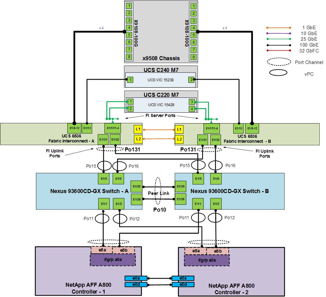
Figure 14 shows various hardware components and the network connections for the IP-based FlexPod design for Generative AI Inferencing.
Figure 14. FlexPod Datacenter Physical Topology for IP-based Storage Access
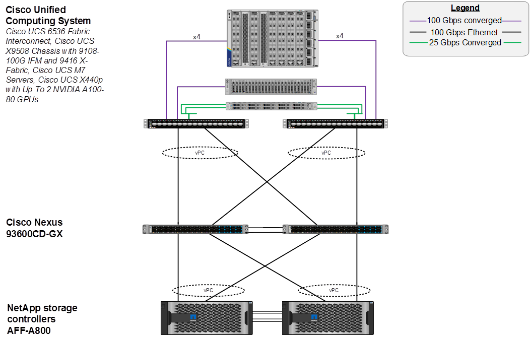
The reference hardware configuration includes:
● Two Cisco Nexus 93600CD-GX Switches in Cisco NX-OS mode provide the switching fabric.
● Two Cisco UCS 6536 Fabric Interconnects (FI) provide the chassis connectivity. Two 100 Gigabit Ethernet ports from each FI, configured as a Port-Channel, are connected to each Nexus 93600CD-GX.
● One Cisco UCS X9508 Chassis connects to fabric interconnects using Cisco UCS UCSX-I-9108-100G IFMs, where four 100 Gigabit Ethernet ports are used on each IOM to connect to the appropriate FI. If additional bandwidth is required, all eight 100G ports can be utilized.
● The Cisco UCS X9508 Chassis is also equipped with a pair of Cisco UCS 9416 X-Fabric modules.
● One NetApp AFF A800 HA pair connects to the Cisco Nexus 93600CD-GX Switches using two 100 GE ports from each controller configured as a Port-Channel.
● One Cisco UCS C240 M7 rack mount server connects to the Fabric Interconnects using two 100 GE ports per server.
● One Cisco UCS C220 M7 rack mount server connects to the Fabric Interconnects using four 25 GE ports per server via breakout.
● Up to two NVIDIA A100-80 GPUs are installed in the Cisco UCS X440p cards and are connected to the Cisco UCS X210C M7 in the adjacent slot by X-Fabric.
● This reference configuration consists of 2 Cisco UCS X210c M7 servers each with an X440p card with 2 NVIDIA A100-80 GPUs, 2 additional Cisco UCS X210c M7 servers, 2 Cisco UCS X210c M6 servers, 1 Cisco UCS C240 M7, and 1 Cisco UCS C220 M7.
FlexPod Multi-Tenant Configuration
In the deployment section of this document, a base FlexPod is setup using Ansible playbooks and following the latest FlexPod Datacenter using IaC with Cisco IMM M7, VMware vSphere 8, and NetApp ONTAP 9.12.1 Deployment Guide. This validation uses NetApp ONTAP 9.13.1, but the Ansible playbooks have been successfully tested with ONTAP 9.13.1. In thinking about a FlexPod Multi-Tenant Configuration, the base FlexPod setup is a setup of the first FlexPod Infrastructure tenant. This CVD adds a second tenant (OCP) to the FlexPod, setting up a platform to run Generative AI Inferencing.
The first question that must be answered in setting up a multi-tenant environment is how the servers are going to be configured and booted. In this FlexPod environment all servers are running the VMware ESXi hypervisor, and we have two tenants. The first decision to be made is whether to run a fully shared infrastructure where both tenants run on all servers, or to dedicate servers to tenants. In this setup, it made the most sense to dedicate servers to the two tenants instead of setting up a fully shared infrastructure. Because this is a virtualized setup, it can be run on a minimum of six ESXi hosts, three for each tenant cluster. In this setup, there are eight total servers available, and the decision was made to dedicate three servers to the FlexPod Infrastructure tenant, where both FlexPod and OCP management VMs reside, and five servers to the OCP cluster, where the three OCP master VMs and three OCP worker VMs reside. The OCP master VMs have minimal requirements and more than one of these VMs can run on a single ESXi host. The OCP worker VMs can also be sized where more than one worker, or one worker and one master can run on a single ESXi host. Given that a separate NetApp Storage Virtual Machine (SVM) is used for each tenant, the second decision to be made is whether to iSCSI SAN boot all servers from the FlexPod Infrastructure SVM or to boot the three FlexPod Management servers from the Infrastructure SVM and the five OCP servers from the OCP SVM. Booting the OCP servers from the OCP SVM would require a new UCS Server Profile to be created with different iSCSI vNICs, different iSCSI boot IP pools in different subnets, and different iSCSI connection policies. Also, because adding a FlexPod tenant mainly involves adding VLANs and a NetApp SVM for a tenant, and the base FlexPod design allows these VLANs to be added to the UCS Domain Profile VLAN Policy, the base UCS Server Profile and VMware vDSs without generating a new Server Profile, it made the most sense to boot all of the servers from the FlexPod Infrastructure VM and use the same Server Profile template for both tenants.
Nexus Switch OCP Tenant Additions
To add the OCP tenant to this FlexPod, we first added four VLANs (one for OCP management, one for OCP NFS, and two for OCP NVMe-TCP) to the switches. We then added those VLANs to the appropriate switchports or port channels. Finally, to simplify OCP NTP setup, we added a switched virtual interface (SVI) in each switch as an OCP-MGMT VLAN interface. Since in NX-OS mode, if you have NTP distribution enabled, any SVI becomes and NTP distribution interface. We also added an OCP Virtual Route Forwarding (VRF) and default gateway in this VRF in case requests come into the OCP SVI from another subnet.
NetApp Storage OCP Tenant Additions
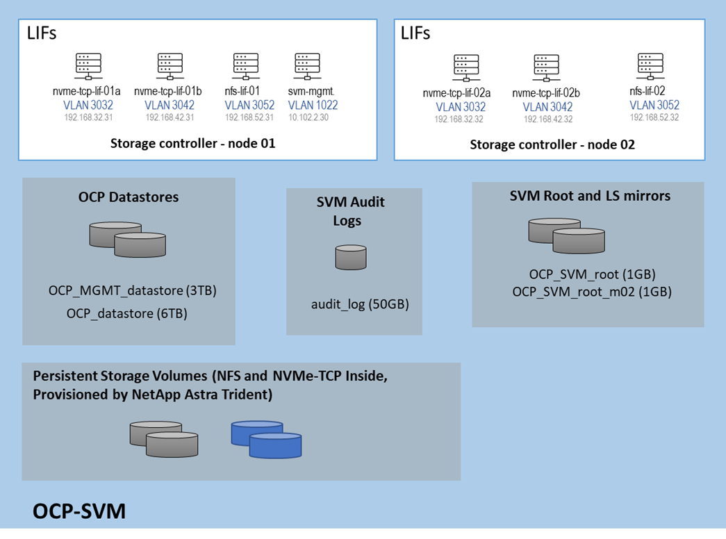
To add the OCP tenant to the NetApp storage we first created VLAN interfaces for the four OCP VLANs, then created corresponding broadcast domains and added the VLAN interfaces to these broadcast domains. After that we followed best practices in creating the OCP SVM and created Logical Interfaces (LIFs) inside that SVM for OCP management and storage interfaces. Next, we added two volumes to become NFS datastores, one for OCP management VMs and the other for OCP master and worker VMs. Finally, we enabled and set a password for the OCP SVM vsadmin user, which was used by NetApp Astra Trident to provision persistent container storage for OCP. The OCP SVM storage layout is shown below. Persistent container storage volumes are also added to this SVM by NetApp Astra Trident.
Figure 15. Initial Storage Layout of NetApp OCP SVM
Cisco UCS OCP Tenant Additions
In Cisco UCS IMM, the VLANs were first need added to the VLAN policy that is a part of the UCS Domain Profile and the Domain Profile was redeployed. The VLANs were then added to the appropriate Ethernet Network Group policies to add them to the vNICs for vDS0 and the iSCSI-NVMe-TCP-vDS. Next, the standard virtualization BIOS Policy was cloned, and some BIOS tokens modified for use on the servers with GPUs. The default BIOS and VMware settings for servers in FlexPod uses a balanced power profile where power is conserved with very little effect on performance. For servers with GPUs, it is recommended to use a high-performance power profile policy and also to enable the BIOS token for Memory Mapped IO above 4GiB. The appropriate Server Profile was cloned, and the cloned BIOS policy was added to cloned template. This new template was then applied to the servers with GPUs. All server profiles were then redeployed and only the servers with GPUs were rebooted.
VMware vSphere OCP Tenant Additions
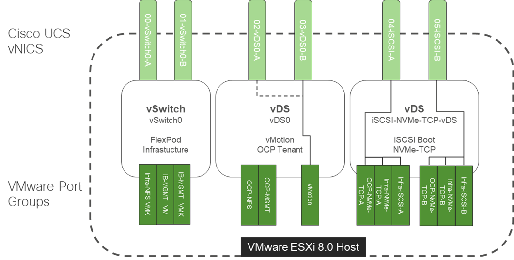
In VMware vCenter, the first thing that was done was to create a separate OCP ESXi cluster to hold the OCP ESXi hosts, this cluster, along with the FlexPod-Management cluster, was setup to be managed with a single image. The image for the FlexPod-Management cluster included the standard FlexPod drivers including the Cisco VIC nenic driver, the NetApp NFS VAAI plugin, and the Cisco UCS tool component. The image for the OCP cluster had all the FlexPod drivers plus the two NVAIE drivers required for the GPUs. The servers used for OCP were then moved to the OCP cluster and remediated to add the NVAIE drivers. Port groups were added to the two vDSs for OCP-MGMT, OCP-NFS, OCP-NVMe-TCP-A, and OCP-NVMe-TCP-B. The Infra-NVMe-TCP VMkernel ports were removed from the OCP servers and an OCP-NFS VMkernel port was added to each OCP host and to each FlexPod-Management host. It was not necessary to configure OCP NVMe-TCP VMkernel ports since OCP NVMe-TCP was only used to map persistent storage directly to the worker VMs. The OCP-MGMT datastore was mounted on all ESXi hosts and the OCP datastore was then mounted only on the OCP hosts. This mounting allowed the OCP management VMs (Windows AD and OCP Installer) to run in either the FlexPod-Management or OCP cluster. Finally, the Hardware Power Policy for the ESXi hosts with GPUs was changed to High performance.
VMware VMs can be successfully live migrated between Cisco UCS M7 servers with Intel 4th Generation Xeon Scalable CPUs and Cisco UCS M6 servers with Intel 3rd Generation Xeon Scalable CPUs. This capability allowed us to mix Cisco UCS M7 and M6 servers in the same VMware ESXi cluster and have vMotion without using Enhanced vMotion Compatibility (EVC).
The VMware network design with OCP included is shown in Figure 16. This diagram shows the base FlexPod VMware Network Design with pinning and the OCP tenant port groups added. In many ways, this diagram sums up the network design of the FlexPod. It shows how tenant connectivity can be added to the FlexPod, and it provides a platform to add additional tenants in a consistent way.
Figure 16. VMware Network Design with OCP Tenant
To install Red Hat OCP, first two Windows AD/DNS/DHCP server VMs, each with 4 network interfaces (OCP-MGMT, OCP-NFS, OCP-NVMe-TCP-A, and OCP-NVMe-TCP-B) with a DHCP scope for each network interface and required DNS entries for OCP were setup. Next, a Rocky Linux ocp-installer VM was setup. After that, the OCP IPI installer with a yaml file specifying the VMware vCenter IP address, user id, password, cluster, and datastore for OCP was used to install and bring up the OCP cluster. Next, OCP post configuration was done around properly setting up NTP servers and setting up NVMe-TCP. In VMware vCenter the OCP VM template was modified with some advanced settings for connecting PCI devices to VMs and upgraded to VM version 20 to allow for up to 8 vGPUs per worker VM. The OCP Machineset was then modified to resize the worker VMs and to add NFS and NVMe-TCP network interfaces to the worker VMs. These storage interfaces get their IP addresses via DHCP from the OCP AD/DNS/DHCP servers. The number of Machineset replicas was then set to zero then back to three to regenerate the workers.
NVIDIA GPU Operator
After OCP was installed and setup, the NVIDIA GPU Operator was installed to provide vGPU drivers and licensing. The first step is to install and configure an NVIDIA licensing server connected to the NVIDIA cloud. In this validation, an on-prem NVIDIA Delegated License Server (DLS) was installed from OVA and connected to the NVIDIA cloud to receive licenses. A Cloud-base License Server (CLS) in the NVIDIA cloud can also be used. Next, the VMware ESXi host GPU settings were adjusted to Share Direct graphics and vGPUs were assigned to OCP worker nodes. Next, the OCP Node Feature Discovery (NFD) Operator was installed to identify vGPUs connected to worker VMs. Then, the NVIDIA GPU Operator was installed with secure connectivity to the DLS for license retrieval and to the NVIDIA NGC Catalog for retrieval of the NVAIE vGPU driver. Once the NVIDIA GPU Operator was fully up and operational, vGPU licensing was checked to ensure GPU performance. This step also verified that the vGPUs and drivers are properly set up. The final steps were to enable the vGPU Dashboard in the OCP Console and to enable GPU monitoring in VMware vCenter.
NetApp Astra Trident
NetApp Astra Trident was then installed into OCP with Helm and three storage classes for persistent storage created:
● NFS 4.1 with a Single Volume with Shared or Single User Access
● NFS 4.1 with NetApp FlexGroup with Shared or Single User Access
● NVMe-TCP with Single User Access
Once the storage classes were created, a persistent volume claim (PVC) could be created with Trident creating backing storage on the NetApp AFF A800. Then when a pod or container was deployed, the PVC could be used to attach the persistent storage to the pod or container. Data in the persistent storage is not deleted each time a container is recreated meaning the pod can be deleted and a replacement pod automatically added without losing any data in the persistent storage. This capability was used in this solution where the AI Inferencing models were stored in persistent storage and standard containers used for the inferencing server or software. With limited GPU resources, deployments of different inferencing servers could be deleted and re-added without having to re-download the AI Inferencing models. The other aspect of the storage classes was Shared or Single User Access. With the NFS-based Storage Classes, multiple containers and other devices could be attached to the same persistent storage. This could allow more than one Inferencing Servers to share a single AI model repository. In this validation, NFS-based persistent storage was mounted from the OCP Installer VM to allow direct copying of AI models to persistent storage. All three Storage Classes were tested in this validation.
Each layer of this platform was built with base security as a requirement. If further security is needed, please refer to FlexPod Datacenter Zero Trust Framework Design Guide. The FlexPod multi-tenant architecture defined in this document aligns with the model in the Zero Trust document.
The base FlexPod with VMware vSphere architecture was configured, then NVIDIA GPUs and an OCP tenant were added followed by NVAIE on VMware, Red Hat OCP, NVAIE on OCP, and NetApp Astra Trident to build a powerful platform for running Generative AI Inferencing. This layered approach is summarized in the figure below. Each layer was configured with best practices and security, resulting in a high-performance, secure platform for Generative AI Inferencing. This platform can be extended for further AI applications such as Training, Fine Tuning, and Retrieval Augmentation Generation (RAG), provided that the platform is sized for the application.
Figure 17. FlexPod as a Platform for Generative AI Inferencing
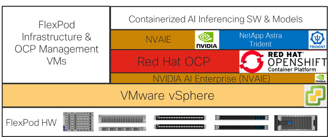
Note: If the NVIDIA physical GPUs are assigned to the Red Hat OCP workers as PCI devices and the NVAIE driver is not installed in VMware ESXi, then the NVAIE layer between VMware vSphere and Red Hat OCP can be removed.
Solution Deployment
This chapter contains the following:
● Deploy the NVIDIA GPU Operator on OCP
Note: The NetApp storage controller and disk shelves should be connected according to best practices for the specific storage controller and disk shelves. For disk shelf cabling, refer to NetApp Support: https://docs.netapp.com/us-en/ontap-systems/index.html
Table 2 lists VLANs configured for setting up the FlexPod environment along with their usage.
| VLAN ID |
Name |
Usage |
IP Subnet used in this deployment |
| 2 |
Native-VLAN |
Use VLAN 2 as native VLAN instead of default VLAN (1). |
|
| 1020 |
OOB-MGMT-VLAN |
Out-of-band management VLAN to connect management ports for various devices |
10.102.0.0/24; GW: 10.102.0.254 |
| 1021 |
IB-MGMT-VLAN |
In-band management VLAN utilized for all in-band management connectivity - for example, ESXi hosts, VM management, and so on. |
10.102.1.0/24; GW: 10.102.1.254 |
| 1022 |
OCP-MGMT |
OCP management traffic VLAN – used in place of VM-Traffic VLAN |
10.102.2.0/24; GW: 10.102.2.254 |
| 3050 |
NFS-VLAN |
NFS VLAN for mounting datastores in ESXi servers for VMs |
192.168.50.0/24 ** |
| 3010 |
iSCSI-A |
iSCSI-A path for storage traffic including boot-from-san traffic |
192.168.10.0/24 ** |
| 3020 |
iSCSI-B |
iSCSI-B path for storage traffic including boot-from-san traffic |
192.168.20.0/24 ** |
| 3030 |
NVMe-TCP-A |
NVMe-TCP-A path when using NVMe-TCP |
192.168.30.0/24 ** |
| 3040 |
NVMe-TCP-B |
NVMe-TCP-B path when using NVMe-TCP |
192.168.40.0/24 ** |
| 3000 |
vMotion |
VMware vMotion traffic |
192.168.0.0/24 ** |
| 3052* |
OCP-NFS |
NFS VLAN for OCP persistent storage and OCP cluster and support VMs |
192.168.52.0/24 ** |
| 3032* |
OCP-NVMe-TCP-A |
NVMe-TCP-A path when using NVMe-TCP for persistent storage |
192.168.32.0/24 ** |
| 3042* |
OCP-NVMe-TCP-B |
NVMe-TCP-B path when using NVMe-TCP for persistent storage |
192.168.42.0/24 ** |
* To be added after initial build.
** IP gateway is not needed since no routing is required for these subnets
Some of the key highlights of VLAN usage are as follows:
● VLAN 1020 allows you to manage and access out-of-band management interfaces of various devices.
● VLAN 1021 is used for in-band management of VMs, ESXi hosts, and other infrastructure services.
● VLAN 1022 is used for OCP management.
● VLAN 3050 provides ESXi hosts access to the NFS datastores hosted on the NetApp Controllers for deploying VMs.
● A pair of iSCSI VLANs (3010 and 3020) is configured to provide access to boot LUNs for ESXi hosts. These VLANs are not needed if you are using FC-only connectivity.
● A pair of NVMe-TCP VLANs (3030 and 3040) are configured to provide access to NVMe datastores when NVMe-TCP is being used.
● VLAN 3000 is used for VM vMotion.
● Additional storage VLANs (3032, 3042, and 3052) are configured for OCP persistent storage and OCP VMs.
Note: iSCSI VLANs are not being configured for OCP persistent storage since NVMe-TCP VLANs are being configured.
Table 3 lists the infrastructure VMs necessary for deployment as outlined in this document.
| Virtual Machine Description |
VLAN |
IP Address |
Comments |
| vCenter Server |
1021 |
10.102.1.100 |
Hosted on either pre-existing management infrastructure (preferred) or on FlexPod |
| NetApp ONTAP Tools for VMware vSphere |
1021 |
10.102.1.99 |
Hosted on FlexPod |
| NetApp SnapCenter Plug-in for VMware vSphere |
1021 |
10.102.1.98 |
Hosted with vCenter on either pre-existing management infrastructure (preferred) or on FlexPod |
| NetApp Active IQ Unified Manager |
1021 |
10.102.1.97 |
Hosted on FlexPod |
| Cisco Intersight Assist |
1021 |
10.102.1.96 |
Hosted on FlexPod |
| FlexPod Ansible |
1021 |
10.102.1.151 |
Hosted on pre-existing management infrastructure and used to run Ansible playbooks to set up the FlexPod |
| OCP AD 1 and 2 |
1022 |
10.102.2.249 and 10.102.2.250 |
Hosted on FlexPod - Microsoft Windows AD servers to provide DNS and DHCP for the OCP environment. These VMs can also be Linux VMs and would use Linux DNS and DHCP server software |
| OCP Installer |
1022 |
10.102.2.10 |
Hosted on FlexPod – Linux VM to install and configure the OCP environment. |
| NVIDIA DLS |
1021 |
10.102.1.17 |
Hosted on FlexPod – OVA to issue NVIDIA vGPU licenses. Could also have been in VLAN 1022. |
Table 4 lists the software revisions for various components of the solution.
| Layer |
Device |
Image Bundle |
Comments |
| Compute |
Cisco UCS |
4.2(3h) |
Cisco UCS GA release for infrastructure including FIs and IFM |
| Cisco UCS X210C M7 |
5.2(0.230092) |
|
|
| Cisco UCS C220/240 M7 |
4.3(2.230270) |
|
|
| GPU |
NVIDIA A100-80 |
535.129.03 |
|
| Network |
Cisco Nexus 93600CD-GX NX-OS |
10.2(6)M |
|
| Storage |
NetApp AFF A800 |
ONTAP 9.13.1P6 |
Latest patch release |
| Software |
Cisco Intersight Assist Appliance |
1.0.9-630 |
1.0.9-630 initially installed and then automatically upgraded to latest release |
| VMware vCenter |
8.0 |
Latest 8.0 Build |
|
| VMware ESXi |
8.0 |
Latest 8.0 Build |
|
| VMware ESXi nenic Ethernet Driver |
2.0.11.0 |
|
|
| NetApp ONTAP Tools for VMware vSphere |
9.13 |
Formerly Virtual Storage Console (VSC) |
|
| NetApp SnapCenter Plug-in for VMware vSphere |
4.9 |
|
|
| NetApp Active IQ Unified Manager |
9.14RC1 |
|
The information in this section is provided as a reference for cabling the physical equipment in a FlexPod environment. To simplify cabling requirements, a cabling diagram was used.
The cabling diagram in this section contains the details for the prescribed and supported configuration of the NetApp AFF 800 running NetApp ONTAP 9.13.1P6.
Note: For any modifications of this prescribed architecture, consult the NetApp Interoperability Matrix Tool (IMT).
Note: This document assumes that out-of-band management ports are plugged into an existing management infrastructure at the deployment site. These interfaces will be used in various configuration steps.
Note: Be sure to use the cabling directions in this section as a guide.
The NetApp storage controller and disk shelves should be connected according to best practices for the specific storage controller and disk shelves. For disk shelf cabling, refer to NetApp Support.
Figure 18 details the cable connections used in the validation lab for the FlexPod topology based on the Cisco UCS 6536 fabric interconnect. Two 100Gb links connect each Cisco UCS Fabric Interconnect to the Cisco Nexus Switches and each NetApp AFF controller to the Cisco Nexus Switches. Additional 1Gb management connections will be needed for out-of-band network switches that sit apart from the FlexPod infrastructure. Each Cisco UCS fabric interconnect and Cisco Nexus switch is connected to the out-of-band network switches, and each AFF controller has a connection to the out-of-band network switches. Layer 3 network connectivity is required between the Out-of-Band (OOB) and In-Band (IB) Management Subnets. This cabling diagram shows the iSCSI-boot configuration.
Figure 18. FlexPod Cabling with Cisco UCS 6536 Fabric Interconnect
Procedure 1. Deploy FlexPod
Step 1. Using the information in the above tables and diagrams, use FlexPod Datacenter using IaC with Cisco IMM M7, VMware vSphere 8, and NetApp ONTAP 9.12.1 to deploy the FlexPod up until the beginning of the FlexPod Management Tools Setup. Rename the VM-Traffic VLAN with a name like OCP-MGMT. Deploy a minimum of 6 servers with ESXi. In this lab setup, 8 total servers were deployed. Deploy an iSCSI-booted FlexPod with NVMe-TCP. The result of this setup will be all servers in the FlexPod-Management cluster.
Note: Do not use the OCP storage VLANs in the initial configuration. Those VLANs will be added later in the process. At the end of the VMware configuration, only configure NVMe-TCP on the three servers that will be used for management and will stay in the FlexPod-Management cluster.
Step 2. If mapping vGPUs to OCP, using your NVIDIA Enterprise account login, connect to https://ui.licensing.nvidia.com/software and download the NVIDIA AI Enterprise 4.1 Software Package for VMware vSphere 8.0. From the downloaded NVIDIA-AI-Enterprise-vSphere-8.0-535.129.03-535.129.03-537.70.zip file extract the NVD-AIE-800_535.129.03-1OEM.800.1.0.20613240_22670890.zip offline bundle and the nvd-gpu-mgmt-daemon_535.129.03-0.0.0000_22676950.zip file.
Step 3. Create an OCP ESXi cluster, turning on vSphere DRS and vSphere HA. Select Manage all hosts in the cluster with a single image and Compose a new image. In FlexPod Datacenter using IaC with Cisco IMM M7, VMware vSphere 8, and NetApp ONTAP 9.12.1, use Create a FlexPod ESXi Custom ISO using VMware vCenter in the Appendix as a guide, set up an image for the OCP cluster with the latest version of ESXi 8.0 (not ESXi 8.0 U1 or U2) with Cisco UCS Addon-ESXi version 4.2.3-b Vendor Addon. Click the Updates tab for the cluster, edit the image and include as Components the two drivers extracted in Step 2 (if mapping vGPUs to OCP) along with all drivers added in the ESXi Ansible scripts. Move the hosts that will be used for OCP to the OCP cluster. Make sure to set the swap file location to Datastore specified by host under the General setting. Put the hosts to be used for OCP in Maintenance Mode and move these hosts to the OCP cluster. Once the OCP hosts are moved to the OCP cluster, go to the cluster settings and under vSphere Cluster Services, add the vCLS datastore. Select the Updates tab, click REMEDIATE ALL and follow the prompts to Remediate all of the OCP hosts.
Note: If mapping the full physical GPUs to OCP workers as PCI devices, do not include the NVAIE driver or nvd-gpu-mgmt-daemon in the cluster image.
Step 4. Set up an image for the FlexPod-Management cluster with the latest version of ESXi 8.0 (not ESXi 8.0 U1 or U2) with Cisco UCS Addon-ESXi version 4.2.3-b Vendor Addon. Click the Updates tab for the cluster, edit the image and include as Components all drivers added in the ESXi Ansible scripts. It is not necessary to add the NVIDIA drivers to this cluster image. Select the Updates tab, click REMEDIATE ALL and follow the prompts to Remediate all of the FlexPod-Management hosts.
Step 5. Return to FlexPod Datacenter using IaC with Cisco IMM M7, VMware vSphere 8, and NetApp ONTAP 9.12.1 and complete the management tools installation and Cisco Intersight integration, including creating a FlexPod Integrated System.
Note: In order to do a first-time Intersight HCL check, it may be necessary to log into each VMware ESXi host with ssh and run python /opt/ucs_tool_esxi/ucs_host_inventory.py
Use the following procedures and steps to add an OCP tenant to your FlexPod so that OCP can be installed to build a platform to install AI Generative Inferencing software.
Procedure 1. Configure Nexus Switches for the OCP Tenant
Run the following commands to add NTP distribution interfaces to the switches and for VLANs used for OCP persistent storage access. Execute these steps in an ssh session on both switches.
config t
vrf context OCP
description VRF for routing OCP subnets/VLANs
ip route 0.0.0.0/0 10.102.2.254
interface VLAN1022
vrf member OCP
ip address 10.102.2.3/24 # Use 10.102.2.4/24 in the second switch
no shutdown
exit
vlan 3032
name OCP-NVMe-TCP-A
vlan 3042
name OCP-NVMe-TCP-B
vlan 3052
name OCP-NFS
exit
int Po10,Po11,Po12,Po15,Po16
switchport trunk allowed vlan add 3032,3042,3052 # Add OCP Storage VLANs to vPC Peer Link, Storage Interfaces, and UCS FI Uplink Interfaces
int Po11,Po12,Po127
switchport trunk allowed vlan add 1022 # Add OCP-MGMT VLAN to Storage Interfaces and make sure it is on the Uplink Interface
copy r s
Procedure 2. Configure NetApp ONTAP Storage for the OCP Tenant
Complete the following steps to add VLAN ports and broadcast domains to the NetApp storage for the OCP-MGMT and OCP storage VLANs, and then add and configure the SVM for OCP persistent storage volumes, including adding management, NFS, and NVMe-TCP LIFs and the vsadmin user and password. Execute these steps from the storage cluster ssh interface.
Step 1. Create the OCP-MGMT, OCP-NVMe-TCP-A , and OCP-NVMe-TCP-B, OCP-NFS broadcast domain with a maximum transmission unit (MTU) of 9000, run the following commands in ONTAP:
network port broadcast-domain create -broadcast-domain OCP-MGMT -mtu 1500
network port broadcast-domain create -broadcast-domain OCP-NVMe-TCP-A -mtu 9000
network port broadcast-domain create -broadcast-domain OCP-NVMe-TCP-B -mtu 9000
network port broadcast-domain create -broadcast-domain OCP-NFS -mtu 9000
Step 2. Create the OCP management VLAN ports and add them to the OCP management broadcast domain:
network port vlan create -node AA02-A800-01 -vlan-name a0a-1022
network port vlan create -node AA02-A800-02 -vlan-name a0a-1022
network port broadcast-domain add-ports -broadcast-domain OCP-MGMT -ports AA02-A800-01:a0a-1022,AA02-A800-02:a0a-1022
Step 3. Create the OCP NVMe-TCP VLAN ports and add them to the broadcast domain:
network port vlan create -node AA02-A800-01 -vlan-name a0a-3032
network port vlan create -node AA02-A800-02 -vlan-name a0a-3032
network port broadcast-domain add-ports -broadcast-domain OCP-NVMe-TCP-A -ports AA02-A800-01:a0a-3032,AA02-A800-02:a0a-3032
network port vlan create -node AA02-A800-01 -vlan-name a0a-3042
network port vlan create -node AA02-A800-02 -vlan-name a0a-3042
network port broadcast-domain add-ports -broadcast-domain OCP-NVMe-TCP-B -ports AA02-A800-01:a0a-3042,AA02-A800-02:a0a-3042
Step 4. Create the OCP NFS VLAN ports and add them to the OCP NFS broadcast domain:
network port vlan create -node AA02-A800-01 -vlan-name a0a-3052
network port vlan create -node AA02-A800-02 -vlan-name a0a-3052
network port broadcast-domain add-ports -broadcast-domain OCP-NFS -ports AA02-A800-01:a0a-3052,AA02-A800-02:a0a-3052
Step 5. Create SVM (Storage Virtual Machine). Run the vserver create command:
vserver create -vserver OCP-SVM
Step 6. Add the required data protocols to the SVM & Remove the unused data protocols from the SVM:
vserver add-protocols -vserver OCP-SVM -protocols nfs,nvme
vserver remove-protocols -vserver OCP-SVM -protocols cifs,fcp,iscsi,s3
Step 7. Add the two data aggregates to the OCP-SVM aggregate list & Enable and run the NFS protocol in the SVM::
vserver modify -vserver OCP-SVM -aggr-list AA02_A800_01_NVME_SSD_1,AA02_A800_02_NVME_SSD_1
vserver nfs create -vserver OCP-SVM -udp disabled -v3 enabled -v4.1 enabled -vstorage enabled
Step 8. Create a Load-Sharing Mirror of the SVM Root Volume. Create a volume to be the load-sharing mirror of the infrastructure SVM root volume only on the node that does not have the Root Volume:
volume show -vserver OCP-SVM # Identify the aggregate and node where the root volume is located.
volume create -vserver OCP-SVM -volume OCP_SVM_root_lsm0<x> -aggregate AA02_A800_0<x>_NVME_SSD_1 -size 1GB -type DP # Create the mirror volume on the other node.
Step 9. Create the mirroring relationship:
snapmirror create -source-path OCP-SVM:OCP_SVM_root -destination-path OCP-SVM:OCP_SVM_root_lsm0<x> -type LS -schedule 15min
Step 10. Initialize the mirroring relationship & verify the same:
snapmirror initialize-ls-set -source-path OCP-SVM:OCP_SVM_root
snapmirror show -vserver OCP-SVM
Progress
Source Destination Mirror Relationship Total Last
Path Type Path State Status Progress Healthy Updated
----------- ---- ------------ ------- -------------- --------- ------- --------
AA02-A800://OCP-SVM/OCP_SVM_root
LS AA02-A800://OCP-SVM/OCP_SVM_root_lsm01
Snapmirrored
Idle - true -
Step 11. Create NVMe Service:
vserver nvme create -vserver OCP-SVM -status-admin up
vserver nvme show -vserver OCP-SVM
Vserver Name: OCP-SVM
Administrative Status: up
Discovery Subsystem NQN: nqn.1992-08.com.netapp:sn.00f61b2cb31b11ee8d1700a098e217cb:discovery
Step 12. To create login banner for the SVM, run the following command:
security login banner modify -vserver OCP-SVM -message "This OCP-SVM is reserved for authorized users only!"
Step 13. Remove insecure ciphers from the SVM. Ciphers with the suffix CBC are considered insecure. To remove the CBC ciphers, run the following NetApp ONTAP command:
security ssh remove -vserver OCP-SVM -ciphers aes256-cbc,aes192-cbc,aes128-cbc,3des-cbc
Step 14. Create a new rule for the SVM NFS subnet in the default export policy and assign the policy to the SVM:
vserver export-policy rule create -vserver OCP-SVM -policyname default -ruleindex 1 -protocol nfs -clientmatch 192.168.52.0/24 -rorule sys -rwrule sys -superuser sys -allow-suid true
volume modify –vserver OCP-SVM –volume OCP_SVM_root –policy default
Step 15. Create FlexVol Volumes.
The following information is required to create a NetApp FlexVol volume:
● The volume name
● The volume size
● The aggregate on which the volume exists
volume create -vserver OCP-SVM -volume audit_log -aggregate AA02_A800_01_NVME_SSD_1 -size 50GB -state online -policy default -junction-path /audit_log -space-guarantee none -percent-snapshot-space 0
Step 16. Update set of load-sharing mirrors using the following command:
snapmirror update-ls-set -source-path OCP-SVM:OCP_SVM_root
Step 17. Run the following commands to create NFS LIFs:
network interface create -vserver OCP-SVM -lif nfs-lif-01 -service-policy default-data-files -home-node AA02-A800-01 -home-port a0a-3052 -address 192.168.52.31 -netmask 255.255.255.0 -status-admin up -failover-policy broadcast-domain-wide -auto-revert true
network interface create -vserver OCP-SVM -lif nfs-lif-02 -service-policy default-data-files -home-node AA02-A800-02 -home-port a0a-3052 -address 192.168.52.32 -netmask 255.255.255.0 -status-admin up -failover-policy broadcast-domain-wide -auto-revert true
Step 18. Run the following commands to create NVMe-TCP LIFs:
network interface create -vserver OCP-SVM -lif nvme-tcp-lif-01a -service-policy default-data-nvme-tcp -home-node AA02-A800-01 -home-port a0a-3032 -address 192.168.32.31 -netmask 255.255.255.0 -status-admin up
network interface create -vserver OCP-SVM -lif nvme-tcp-lif-01b -service-policy default-data-nvme-tcp -home-node AA02-A800-01 -home-port a0a-3042 -address 192.168.42.31 -netmask 255.255.255.0 -status-admin up
network interface create -vserver OCP-SVM -lif nvme-tcp-lif-02a -service-policy default-data-nvme-tcp -home-node AA02-A800-02 -home-port a0a-3032 -address 192.168.32.32 -netmask 255.255.255.0 -status-admin up
network interface create -vserver OCP-SVM -lif nvme-tcp-lif-02b -service-policy default-data-nvme-tcp -home-node AA02-A800-02 -home-port a0a-3042 -address 192.168.42.32 -netmask 255.255.255.0 -status-admin up
Step 19. Run the following commands to create SVM-MGMT LIF:
network interface create -vserver OCP-SVM -lif svm-mgmt -service-policy default-management -home-node AA02-A800-01 -home-port a0a-1022 -address 10.102.2.30 -netmask 255.255.255.0 -status-admin up -failover-policy broadcast-domain-wide -auto-revert true
Step 20. Run the following commands to verify:
network interface show -vserver OCP-SVM
Logical Status Network Current Current Is
Vserver Interface Admin/Oper Address/Mask Node Port Home
----------- ---------- ---------- ------------------ ------------- ------- ----
OCP-SVM
nfs-lif-01 up/up 192.168.52.31/24 AA02-A800-01 a0a-3052
true
nfs-lif-02 up/up 192.168.52.32/24 AA02-A800-02 a0a-3052
true
nvme-tcp-lif-01a
up/up 192.168.32.31/24 AA02-A800-01 a0a-3032
true
nvme-tcp-lif-01b
up/up 192.168.42.31/24 AA02-A800-01 a0a-3042
true
nvme-tcp-lif-02a
up/up 192.168.32.32/24 AA02-A800-02 a0a-3032
true
nvme-tcp-lif-02b
up/up 192.168.42.32/24 AA02-A800-02 a0a-3042
true
svm-mgmt up/up 10.102.2.30/24 AA02-A800-01 a0a-1022
true
7 entries were displayed.
Step 21. Create a default route that enables the SVM management interface to reach the outside world:
network route create -vserver OCP-SVM -destination 0.0.0.0/0 -gateway 10.102.2.254
Step 22. Set password for SVM vsadmin user and unlock the user.
security login password -username vsadmin -vserver OCP-SVM
Enter a new password:
Enter it again:
security login unlock -username vsadmin -vserver OCP-SVM
Step 23. Create and enable auditing configuration for the SVM.
vserver audit create -vserver OCP-SVM -destination /audit_log
vserver audit enable -vserver OCP-SVM
Procedure 3. Configure Cisco UCS IMM for the OCP Tenant
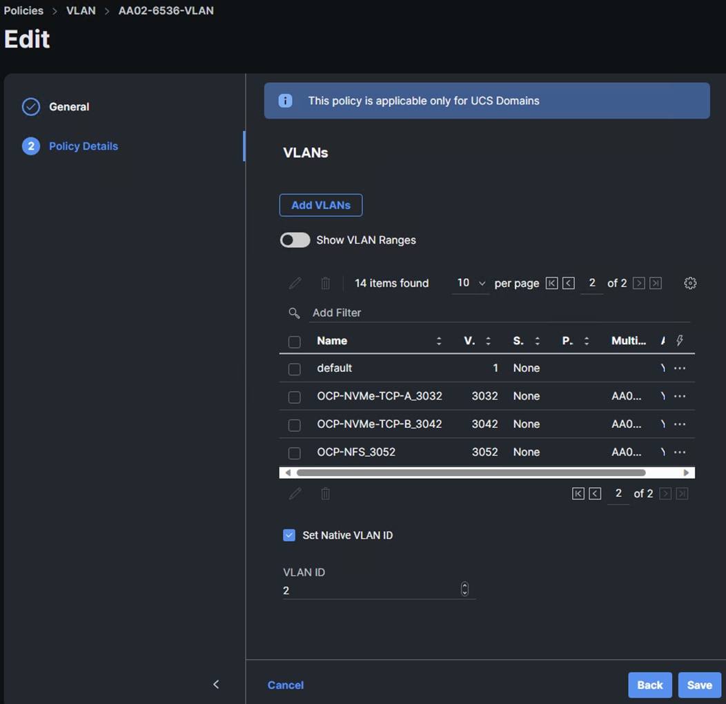
Use the following steps to add VLANs and BIOS Policy settings to IMM. Execute these steps from Cisco Intersight.
Step 1. In Cisco Intersight, select Infrastructure Service > Policies. Add a Filter of Type VLAN. Select and edit the UCS Domain VLAN policy (for example, AA02-6536-VLAN). Click Next. As you did when building the FlexPod, add the OCP-NVMe-TCP-A, OCP-NVMe-TCP-B, and OCP-NFS VLANs to the policy. Click Save to save the policy.
Step 2. In Cisco Intersight, select Infrastructure Service > Profiles > UCS Domain Profiles. Click the ellipses to the right of the UCS Domain Profile and select Deploy. Click Deploy to deploy the profile.
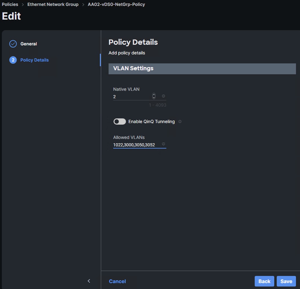
Step 3. In Cisco Intersight, select Infrastructure Service > Policies. Add a Filter of Type Ethernet Network Group. Select and edit the vDS0-NetGrp-Policy. Click Next. Add the OCP-NFS VLAN ID to the Allowed VLANs list. Click Save.
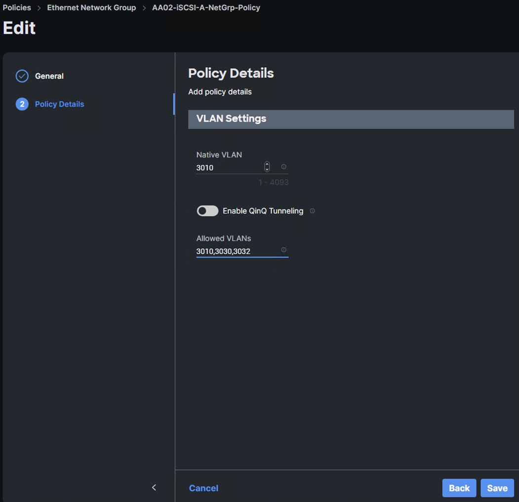
Step 4. In Cisco Intersight, select Infrastructure Service > Policies. Add a Filter of Type Ethernet Network Group. Select and edit the iSCSI-A-NetGrp-Policy. Click Next. Add the OCP-NVMe-TCP-A VLAN ID to the Allowed VLANs list. Click Save.
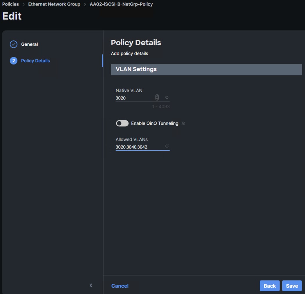
Step 5. In Cisco Intersight, select Infrastructure Service > Policies. Add a Filter of Type Ethernet Network Group. Select and edit the iSCSI-B-NetGrp-Policy. Click Next. Add the OCP-NVMe-TCP-B VLAN ID to the Allowed VLANs list. Click Save.
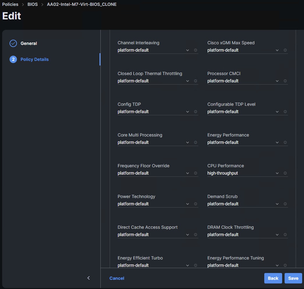
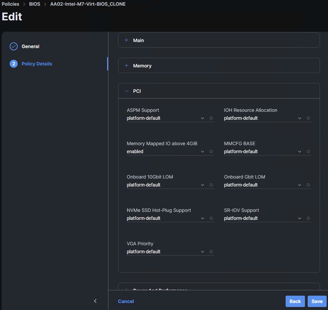
Step 6. In Cisco Intersight, select Infrastructure Service > Policies. In the center pane, click Add Filter and add a filter of Type BIOS. To the right of the BIOS Policy that applies to your server(s) with GPUs, click the ellipses and select Clone. Modify the clone’s Policy Name (for example, add -GPU to the original policy name to get Prefix-Intel-M7-Virt-BIOS-GPU. Click Clone to clone the BIOS Policy.
Step 7. Refresh the page to update the list of policies. The cloned policy should now appear at the top of the list. To the right of the cloned policy, click the ellipses and select Edit. Click Next. Expand Processor and set the CPU Performance token to high-throughput. Expand PCI and set the Memory Mapped IO above 4GiB token to enabled. Click Save to save the updated policy.
Step 8. In Cisco Intersight, select Infrastructure Service > Templates. To the right of the template being used on the servers that have GPUs, click the ellipses and select Clone. Leave Number of Clones set at 1 and click Next. Add -GPU- in the template name (for example, Prefix-M7-Intel-5G-VIC-GPU-iSCSI-Boot-Template) and click Clone.
Step 9. In the Templates list, click the ellipses to the right of the newly cloned GPU template and select Edit. Click Next to get to the Compute Configuration window. Place the cursor on the BIOS line and click the x to remove the current BIOS policy. Click Detach to complete the removal. On the BIOS line, click Select Policy and select the GPU BIOS policy. Once the check appears next to the updated BIOS policy, click Close.
Step 10. In Cisco Intersight, select Infrastructure Service > Profiles > UCS Server Profiles. For each server that has GPU(s) installed, on the corresponding profile, click the ellipses to the right of the profile and select Detach from Template. Once the profile is detached from the template, click the ellipses again and select Attach to Template. Select the GPU template and click Next. Click Attach.
Step 11. The UCS IMM Ansible scripts set the VMware-HighTrf Ethernet Adapter policy on the vDS0 vNICs. To change this to the AA02-EthAdapter-16RXQs-5G policy, in Cisco Intersight, select Infrastructure Service > Configure > Policies. Add a filter of Type LAN Connectivity. Click the ellipses to the right of the policy used for the OCP servers and select Edit. Click Next. Select the 02-vDS0-A vNIC and click the pencil icon to edit the vNIC. Scroll down and click the x to remove the existing Ethernet Adapter policy. Click Ethernet Adapter > Select Policy to select a new policy. Choose AA02-EthAdapter-16RXQs-5G and click Update. Repeat to set the AA02-EthAdapter-16RXQs-5G policy for the 03-vDS0-B vNIC. Click Save & Deploy then Save & Proceed to save the change to the UCS Server Profiles.
Step 12. In the Deploy Server Profiles popup, select Reboot Immediately to Activate and click Deploy to deploy the profiles.
Procedure 4. Configure VMware vSphere for the OCP Tenant
Use the following steps to add distributed switch port groups, VMkernel ports, and a datastore to the OCP VMware ESXi hosts. Execute these steps from the VMware vCenter web interface.
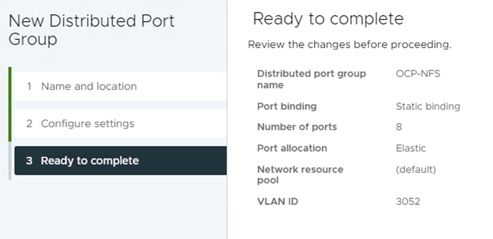
Step 1. In VMware vCenter, select Inventory > Networking, expand the vCenter and Datacenter, and right-click vDS0. Select Distributed Port Group > New Distributed Port Group. Name the port group OCP-NFS and click NEXT. Select VLAN type VLAN and enter the OCP NFS VLAN ID. Click NEXT. Click FINISH to complete adding the port group.
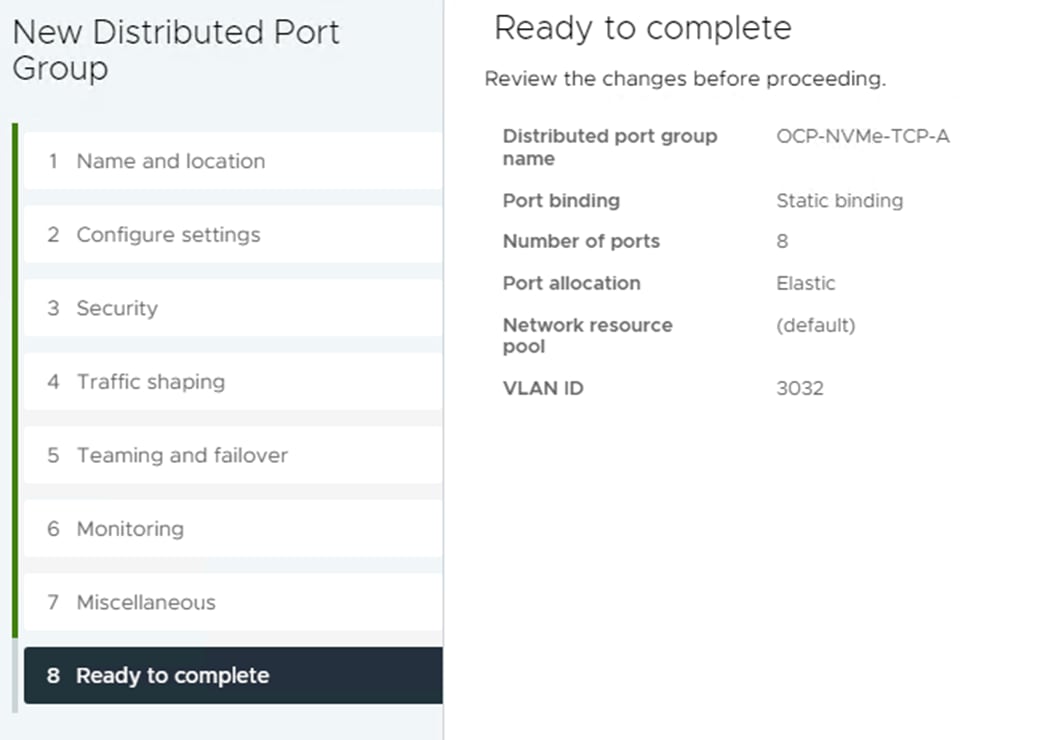
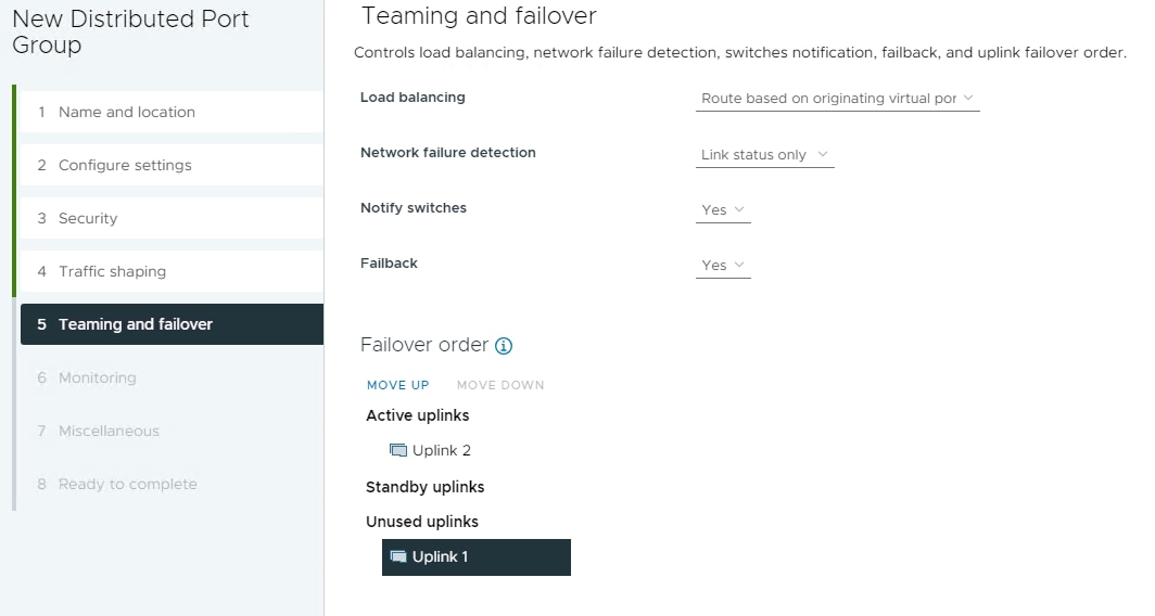
Step 2. Right-click iSCSI-NVMe-TCP-vDS. Select Distributed Port Group > New Distributed Port Group. Name the port group OCP-NVMe-TCP-A and click NEXT. Select VLAN type VLAN and enter the OCP NVMe-TCP-A VLAN ID. Select Customize default policies configuration. Click NEXT through the prompts to get to “5 Teaming and Failover”. Move Uplink 2 under “Unused uplinks” to pin all OCP-NVMe-TCP-A traffic to Fabric A. Click NEXT through the process. Click FINISH to complete adding the port group.
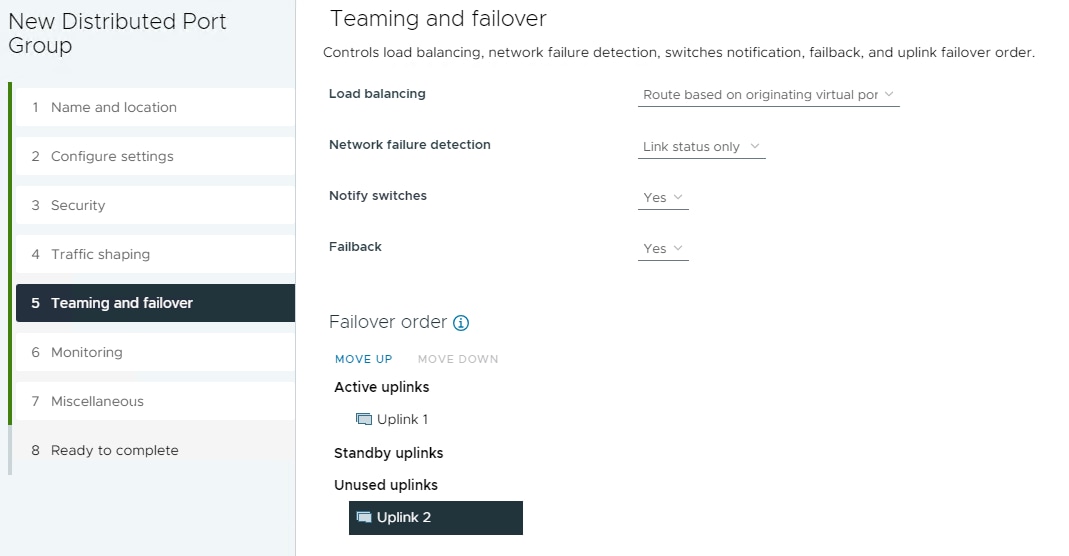
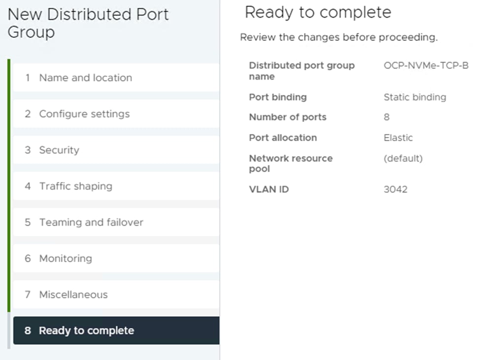
Step 3. Right-click iSCSI-NVMe-TCP-vDS. Select Distributed Port Group > New Distributed Port Group. Name the port group OCP-NVMe-TCP-B and click NEXT. Select VLAN type VLAN and enter the OCP NVMe-TCP-B VLAN ID. Select Customize default policies configuration. Click NEXT through the prompts to get to “5 Teaming and Failover.” Move Uplink 1 under “Unused uplinks” to pin all OCP-NVMe-TCP-B traffic to Fabric B. Click NEXT through the process. Click FINISH to complete adding the port group.
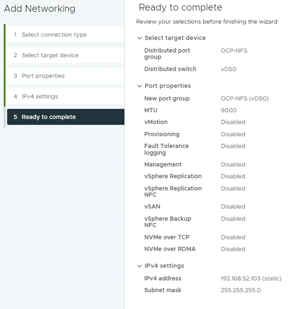
Step 4. Select Hosts and Clusters. Expand the vCenter, Datacenter, and OCP Cluster. Select each OCP ESXi host and select Configure > VMkernel Adapters. Remove the vmk5 (Infra-NVMe-TCP-A) and vmk6 (Infra-NVMe-TCP-B) adapters (not needed for OCP hosts). Click ADD NETWORKING. With “VMkernel Network Adapter” selected, click NEXT. Select the OCP-NFS network and click NEXT. Leave all settings default, including MTU 9000, and click NEXT. Select Use static IPv4 settings and fill in an IPv4 address and Subnet mask. Click NEXT. Click FINISH to complete adding the VMkernel port. Repeat this process for all six OCP ESXi hosts.
Note: It is not necessary to add VMkernel ports for NVMe-TCP since the NVMe-TCP namespaces will be mounted from within OCP.
Step 5. As detailed in Step 4, add an OCP-NFS VMkernel port to each of the FlexPod-Management VMware ESXi hosts.
Step 6. In VMware vCenter, select NetApp ONTAP Tools. Select Storage Systems. Click REDISCOVER ALL. Select Inventory > Hosts and Clusters. Right-click the OCP cluster and select NetApp ONTAP tools > Provision Datastore. Leave NFS selected and name the datastore OCP_MGMT_datastore. Set the size to at least 3TB and select NFS 4.1. Uncheck “Use storage capability profile for provisioning.” Click NEXT.
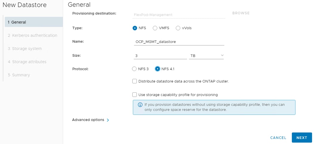
Step 7. Leave “Don’t use Kerberos authentication” selected and click NEXT. Select your Storage system and the OCP-SVM. Click NEXT. Select the aggregate for storage node 02, expand the Advanced options and select Space reserve Thin and click NEXT.
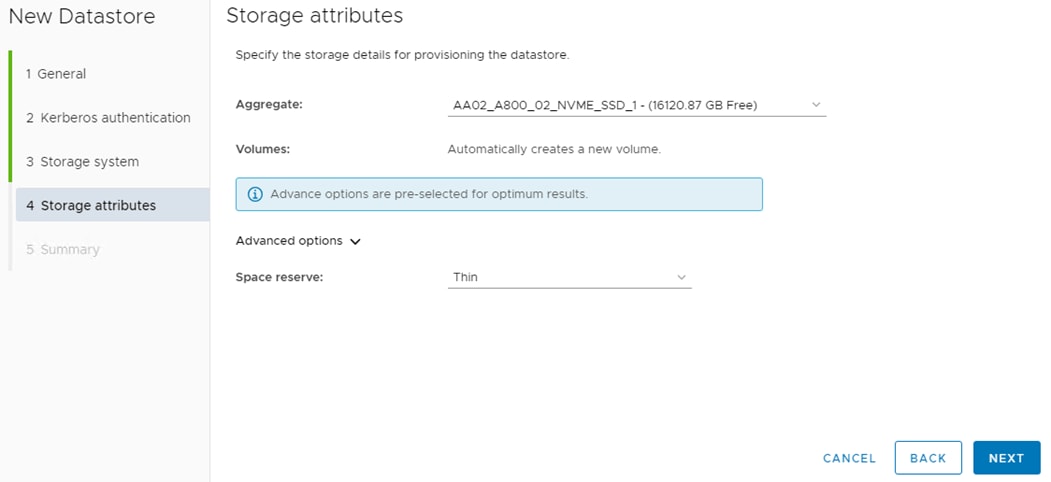
Step 8. Click FINISH to complete creating the datastore for OCP management virtual machines (VMs).
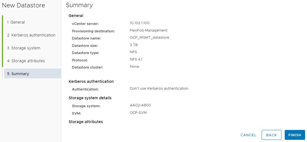
Step 9. Repeat steps 6-8 to create an NFS 4.1 6TB OCP_datastore in the OCP-SVM on the storage node 01 aggregate to hold the OCP master and worker VMs.
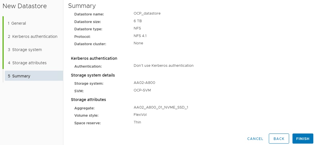
Step 10. Select Inventory > Datastores. Right-click the OCP_MGMT_datastore and select Mount Datastore to Additional Hosts. Select all of the FlexPod-Management hosts and click NEXT. Click FINISH to complete adding the OCP_MGMT_datastore to the FlexPod-Management hosts.
Step 11. Under Inventory, select the first server that has GPU(s). In the center pane, select the Configure tab. In the list on the left side of the center pane, select Hardware > Overview. In the center pane, scroll down to Power Management and click EDIT POWER POLICY. Select High performance and click OK. Repeat this step for all servers that have GPUs.
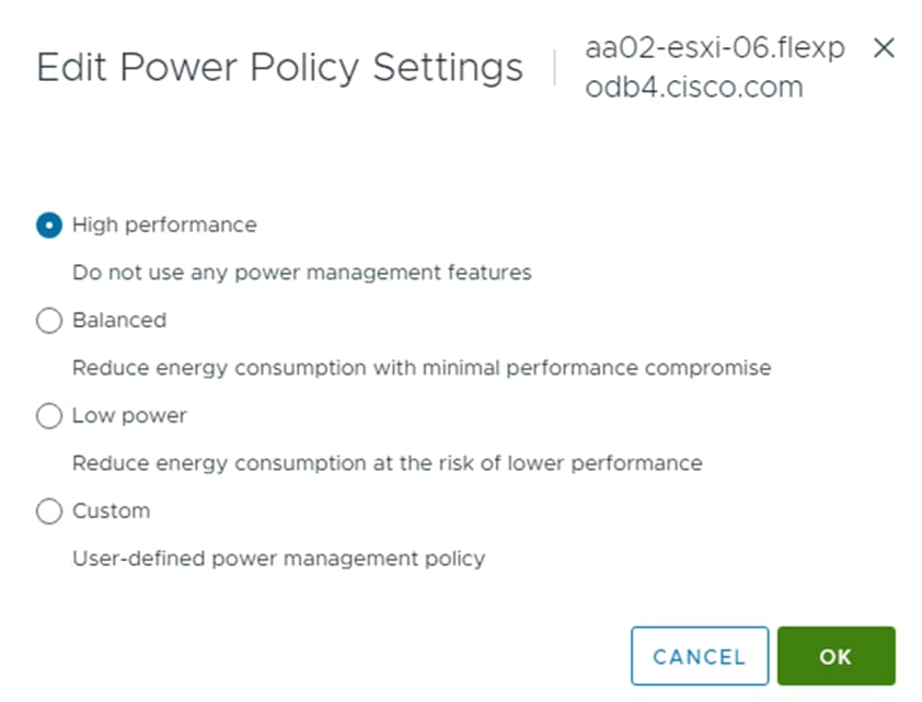
Procedure 1. Deploy DNS/DHCP Servers
Step 1. Deploy two Windows AD server VMs (Server 2019 was used in this validation) in the FlexPod-Management ESXi cluster and in the OCP_MGMT_datastore.
Step 2. Deploy 4 vmxnet3 network interfaces (one each in the OCP-MGMT, OCP-NFS, OCP-NVMe-TCP-A, and OCP-NVMe-TCP-B vDS port groups) on each VM.
Step 3. Install Windows Server Standard on each VM. When each VM boots up, install VMware Tools, then open Control Panel and open Network and Sharing Center.
Step 4. On the left select Change adapter settings.
Step 5. In VMware vCenter, right-click the VM and select Edit Settings. Expand each network adapter to see its MAC address.
Step 6. Back in Windows, in the Network Connections window, right-click each adapter and select Status, then select Details. You can determine which adapter is open by matching the MAC address from the Details window with the MAC address in the VM’s Edit Settings window.
Step 7. Once you have determined which interface you have open, close the Details window, and click Properties.
Step 8. Set the interface’s IPV4 address and disable IPV6 if desired. Click OK to save the IP settings. If this interface is an NFS or NVMe-TCP storage interface, click Properties again, then click Configure to configure the Ethernet Adapter.
Step 9. Select the Advanced tab, then Jumbo Packet in the list. Set the value to 9000 to enable Jumbo frames on this interface. Click OK. Right-click the interface and select Rename to give the interface a more appropriate name. Assign IPs on all interfaces, set Jumbo frames on the three storage interfaces, and rename all interfaces on both Windows AD VMs.
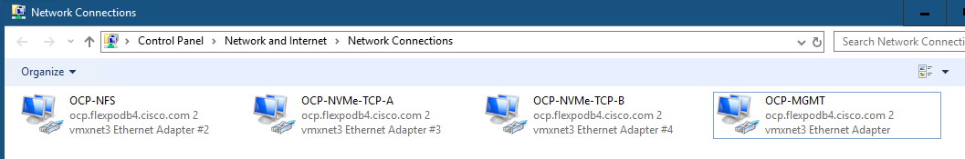
Step 10. On both Windows AD VMs, use Server Manager to add the Active Directory Domain Services and DHCP Server roles and associated Features.
Step 11. After the role installation on the first server, create a domain of the format OCPDomainName.ExistingFlexPodDomain.
Note: In this validation, ocp.flexpodb4.cisco.com was created as a new domain in a new forest. Create this domain according to your organizational policies.
Step 12. When promoting this domain controller, make sure to add the DNS server and create a DNS delegation in your existing FlexPod DNS domain. Once AD is fully installed on the first VM, install Active Directory Domain Services and DHCP Server on the second VM by adding a domain controller to the existing AD domain.
Step 13. Once AD, DNS, and DHCP are installed on both VMs and you have a working/replicating domain, go into DNS on the first VM and configure reverse lookup zones. The following two Host (A) records need to be created in DNS for OCP to work:
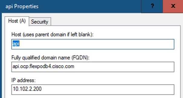
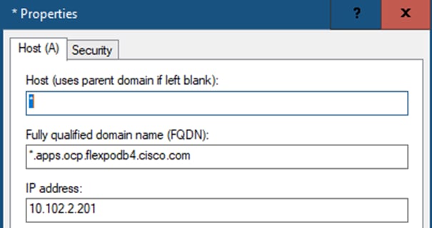
Note: The records show, api.ocp.flexpodb4.cisco.com and *.apps.ocp.flexpodb4.cisco.com, are what was used in this validation. Modify these entries for your environment and use IPs that do not conflict with any DHCP scope or static entries.
Step 14. On both Windows AD VMs, open DHCP and authorize the server in the domain. Right-click IPV4 and select Properties.
Step 15. Set the DNS properties as shown below. On the first Windows AD VM, under IPv4, create a scope for the OCP-MGMT subnet and configure scope options for Router, DNS Servers, DNS Domain Name and NTP Servers. Configure failover on the scope with the second Windows AD VM if desired. Create scopes, with failover if desired, for the OCP-NFS, OCP-NVMe-TCP-A, and OCP-NVMe-TCP-B subnets. It is not necessary to create any scope options for the storage subnet scopes.
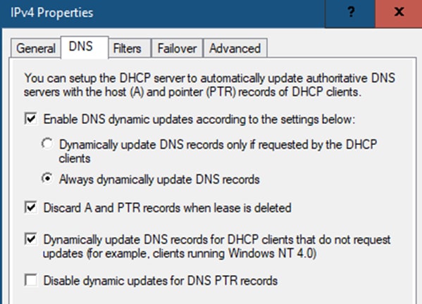
Step 16. When both AD/DNS/DHCP servers are in place, add the DNS domain to the NetApp OCP tenant SVM from the NetApp cluster command line interface:
vserver services name-service dns create -vserver OCP-SVM -domains ocp.flexpodb4.cisco.com,flexpodb4.cisco.com -name-servers 10.102.2.249,10.102.2.250
Procedure 2. Deploy OCP Installer VM
Step 1. Deploy either a RHEL 8 or Rocky Linux 8 OCP-Installer VM in the FlexPod-Management ESXi cluster and in the OCP_MGMT_datastore. Deploy 1 vmxnet3 network interface in the OCP-MGMT subnet.
Step 2. Deploy a 2.1TB thin provisioned hard drive, ensuring that at least 2TB is provisioned in /home. Deploy Server with GUI and create an admin user. Once the VM is up and running, configure NTP servers and do a complete update.
Procedure 3. Deploy and Configure OCP on VMware vSphere
Use the following steps to deploy OCP from the OCP Installer VM.
Step 1. From the OCP Installer VM terminal prompt, run the following:
ssh-keygen -t ed25519 -N '' -f ~/.ssh/id_ed25519
Step 2. Using Firefox, connect to your vCenter FQDN. On the right, under vSphere Web Services SDK, select Download trusted root CA certificates to download these certificates to your Downloads directory. From a terminal prompt, run the following:
cd
cd Downloads
unzip download.zip
sudo cp certs/lin/* /etc/pki/ca-trust/source/anchors
sudo update-ca-trust extract
rm -rf certs
rm download.zip
Step 3. Using Firefox, connect to https://console.redhat.com/openshift/create and log in with your Red Hat account id. Select the Datacenter tab. Select vSphere. Under Automated, select CLI-based. Leaving Linux selected in the drop-down list, click Download installer. Click Download pull secret. Click Download command-line tools.
Step 4. From the OCP Installer VM terminal prompt, run the following:
cd
mkdir ocp-files
mv Downloads/openshift* ocp-files/
mv Downloads/pull-secret ocp-files/
cd ocp-files
tar -xvf openshift-install-linux.tar.gz
./openshift-install create install-config --dir ocp
Select .ssh/id_ed25519
Select vsphere
Enter the vCenter FQDN
Enter administrator@vsphere.local
Enter administrator@vsphere.local’s password
Select the OCP cluster
Select OCP_datastore
Select OCP-MGMT
Enter API IP (entered in DNS)
Enter *.apps IP
Enter Base Domain (for example, flexpodb4.cisco.com)
Enter Cluster Name (for example, ocp)
Copy in Pull Secret
Step 5. Using the Text Editor, edit the install-config.yaml file in the ocp directory specified above and insert “diskType: thin” just after the vCenters user line as shown to setup thin provisioning of the Openshift VM disks as shown:

Step 6. From the OCP Installer VM terminal prompt, deploy the OCP cluster by running the following:
./openshift-install create cluster --dir ocp --log-level=info
Step 7. When the install is complete, you can access Openshift web-console by connecting to the URL listed with the kubeadmin user and password listed. Bookmark this page.
Step 8. To install and use the Openshift CLI, run the following:
mkdir openshift-cli
mv openshift-client-linux.tar.gz openshift-cli/
cd openshift-cli
tar -xvf openshift-client-linux.tar.gz
sudo mv kubectl /usr/sbin/
sudo mv oc /usr/sbin/
export KUBECONFIG=/home/admin/ocp-files/ocp/auth/kubeconfig
oc get nodes
Step 9. To enable permanent oc access to the OCP cluster, run the following:
cp /home/admin/ocp-files/ocp/auth/kubeconfig /home/admin/.kube/config
Step 10. To enable oc tab completion for bash, run the following:
oc completion bash > oc_bash_completion
sudo cp oc_bash_completion /etc/bash_completion.d/
Note: When you open a new terminal window, oc is logged into the OCP cluster and tab completion is enabled.
Step 11. To configure NTP on the Openshift worker and master nodes and NVMe-TCP on the worker nodes, run the following:
cd
cd ocp-files
mkdir ocp-postconfig
cd ocp-postconfig
curl https://mirror.openshift.com/pub/openshift-v4/clients/butane/latest/butane --output butane
chmod +x butane
Step 12. Build the following files in the ocp-postconfig directory with variations for your network:
cat 99-master-chrony-conf-override.bu
variant: openshift
version: 4.14.0
metadata:
name: 99-master-chrony-conf-override
labels:
machineconfiguration.openshift.io/role: master
storage:
files:
- path: /etc/chrony.conf
mode: 0644
overwrite: true
contents:
inline: |
# The Machine Config Operator manages this file.
Server 10.102.2.3 iburst
server 10.102.2.4 iburst
stratumweight 0
driftfile /var/lib/chrony/drift
rtcsync
makestep 10 3
bindcmdaddress 127.0.0.1
bindcmdaddress ::1
keyfile /etc/chrony.keys
commandkey 1
generatecommandkey
noclientlog
logchange 0.5
logdir /var/log/chrony
cat 99-worker-chrony-conf-override.bu
variant: openshift
version: 4.14.0
metadata:
name: 99-worker-chrony-conf-override
labels:
machineconfiguration.openshift.io/role: worker
storage:
files:
- path: /etc/chrony.conf
mode: 0644
overwrite: true
contents:
inline: |
# The Machine Config Operator manages this file.
Server 10.102.2.3 iburst
server 10.102.2.4 iburst
stratumweight 0
driftfile /var/lib/chrony/drift
rtcsync
makestep 10 3
bindcmdaddress 127.0.0.1
bindcmdaddress ::1
keyfile /etc/chrony.keys
commandkey 1
generatecommandkey
noclientlog
logchange 0.5
logdir /var/log/chrony
cat 99-worker-nvme-discovery.bu
variant: openshift
version: 4.14.0
metadata:
name: 99-worker-nvme-discovery
labels:
machineconfiguration.openshift.io/role: worker
openshift:
kernel_arguments:
- loglevel=7
storage:
files:
- path: /etc/nvme/discovery.conf
mode: 0644
overwrite: true
contents:
inline: |
--transport=tcp --traddr=192.168.32.31 --trsvcid=8009
--transport=tcp --traddr=192.168.42.32 --trsvcid=8009
Step 13. Create .yaml files from the butane files with butane, then load the configurations into Openshift:
./butane 99-master-chrony-conf-override.bu -o ./99-master-chrony-conf-override.yaml
./butane 99-worker-chrony-conf-override.bu -o ./99-worker-chrony-conf-override.yaml
./butane 99-worker-nvme-discovery.bu -o ./99-worker-nvme-discovery.yaml
oc create -f 99-master-chrony-conf-override.yaml
oc create -f 99-worker-chrony-conf-override.yaml
oc create -f 99-worker-nvme-discovery.yaml
Step 14. In the Openshift web-console, select Compute > MachineSets. Click the asterick to the right of the machineset and select Edit MachineSet.
Note: In the lab used in this validation, the servers used for OCP worker VMs have 512GB RAM and 72 CPU cores. Because of this, resize the worker VMs to 64 CPUs, 240GB RAM, and a 512GB hard drive. In the annotations, set machine.openshift.io/memoryMb to 2245760 and machine.openshift.io/vCPU to 64. Under spec, set replicas to 0, numCoresPerSocket to 32, diskGiB to 512, memoryMiB to 245760, and numCPUs to 64. Under network > devices add - networkName: OCP-NFS, - networkName: OCP-NVMe-TCP-A, and - networkName: OCP-NVMe-TCP-B. Click Save and then Reload. Two of the three workers should be deleted.
Note: The worker VM memory allocation was calculated assuming that you could run two workers on an ESXi host with vGPUs smaller than the full physical GPU, for example 2 vGPUs with 40G framebuffer instead of 1 vGPU with 80G. Since all VM memory is reserved when using PCI devices and VMware uses 6% of the server memory, on a server with 512GB RAM, VMs can use 480GB RAM. We then divide this by two worker VMs to get 240GB RAM. Size the worker VMs appropriately for your environment.
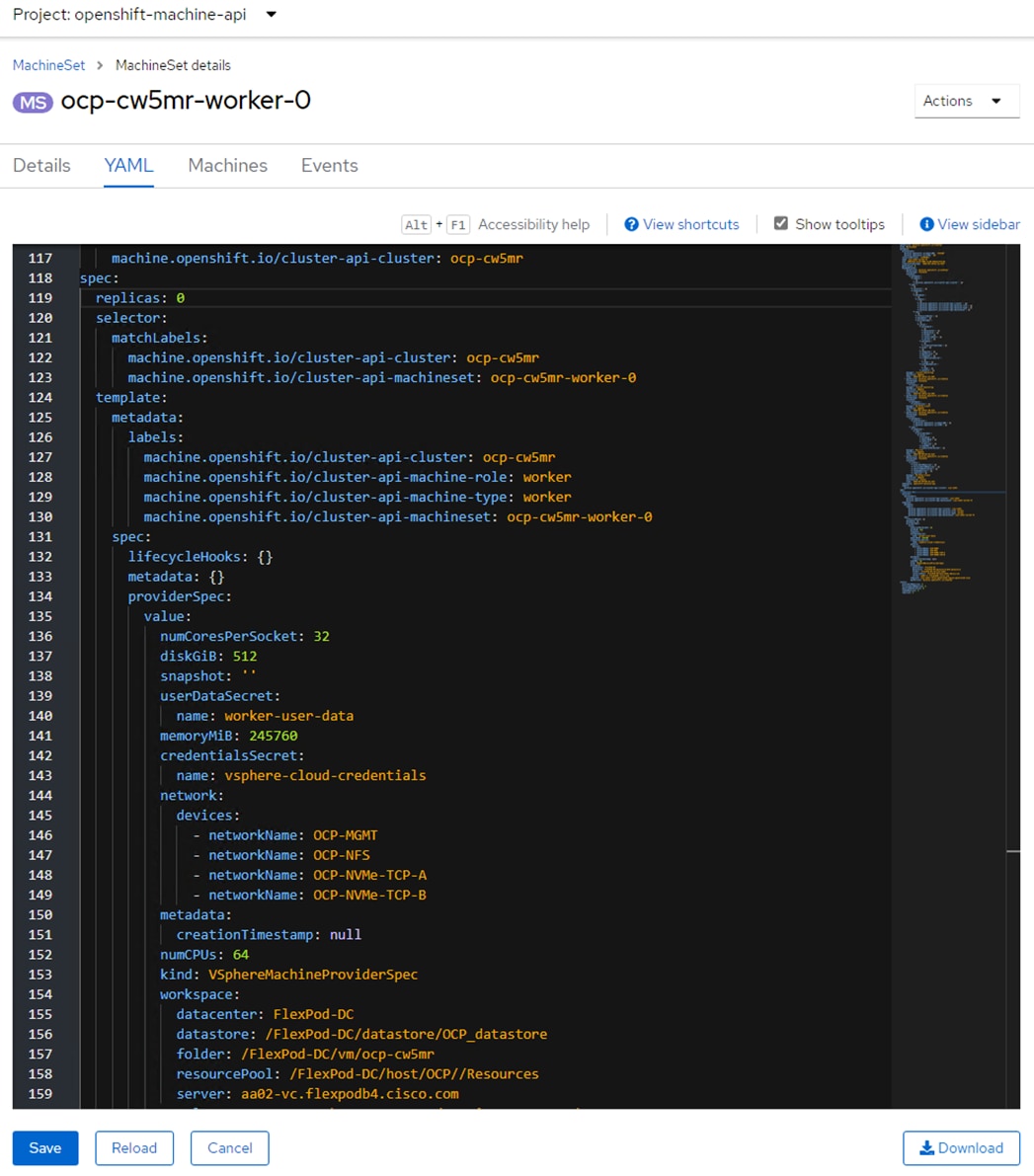
Step 15. In VMware vCenter, put in a host group and a VM group along with affinity rules to lock the OCP master VMs to a set of servers. The worker VMs will be regenerated, do not set affinity rules for them at this time. Select Network and expand the vCenter, the Datacenter, and the ocp folder. Right-click the template and select Convert to Virtual Machine. Click NEXT and FINISH to complete the conversion. Right-click the newly converted VM and select Compatibility > Upgrade VM Compatibility. Click Yes and then click OK to upgrade the VM to hardware version 20.
Step 16. Edit the VM settings following https://docs.nvidia.com/datacenter/cloud-native/openshift/latest/nvaie-with-ocp.html. The RDMA settings are optional but can be entered in for future work.
Step 17. Right-click the template VM and select Template > Convert to Template. Click YES to complete the conversion.
Step 18. Back in the Openshift web-console, select Compute > MachineSets. Click the asterick to the right of the machineset and select Edit Machine count. Change the number from 0 to 3 and click Save. Three new workers will be created.
Step 19. Select Compute > Nodes. Once the three new worker nodes show the Status of Ready, click on the first new worker node and select the Details tab. If any Taints are shown, select the Taint. Click the minus symbol to remove the taint and click Save.
Step 20. Repeat this process for all three of the new workers. The console ingress route will be moved from the one old worker that was remaining to one of the new workers, and the old worker will be deleted. This deletion may take a few minutes. The three workers that are created will have all the specs previously.
Deploy the NVIDIA GPU Operator on OCP
Procedure 1. Deploy NVIDIA License Server
If mapping vGPUs to OCP workers, complete the following steps to deploy an NVIDIA License Server.
Step 1. From https://ui.licensing.nvidia.com/software, download and extract the VMware vSphere NLS License Server (DLS) OVA.
Step 2. Follow https://docs.nvidia.com/license-system/latest/nvidia-license-system-user-guide/index.html#installing-dls-virtual-appliance-on-vmware-vsphere to install the DLS appliance in the FlexPod-Management cluster and in the OCP_MGMT_datastore.
Step 3. Once the OVA is installed and powered on, proceed to https://docs.nvidia.com/license-system/latest/nvidia-license-system-user-guide/index.html#registering-dls-administrator-user.
Step 4. Proceed to https://docs.nvidia.com/license-system/latest/nvidia-license-system-user-guide/index.html#configuring-service-instance and work through Creating a License Server on the NVIDIA Licensing Portal (making sure to add a feature with a number of licenses to cover the number of vGPUs you plan to deploy), DLS Instance Instructions, Registering an on-Premises DLS Instance with the NVIDIA Licensing Portal, Binding a License Server to a Service Instance, and Installing a License Server on a DLS Instance.
Note: If mapping the full physical GPUs to OCP workers as PCI devices, it is not necessary to deploy an NVIDIA License Server.
Procedure 2. Add vGPUs to OCP Worker VMs
If mapping vGPUs to OCP workers, complete the following steps.
Step 1. In VMware vCenter, for each VMware ESXi host that has GPU(s) installed, under Inventory select the ESXi host and then select the Configure tab in the center pane. Select Hardware > Graphics. The GPU(s) should appear under Graphics Devices. Click HOST GRAPHICS then click EDIT. Select Shared Direct Vendor shared passthrough graphics and make sure Spread VMs across GPUs (best performance) is selected. Click OK.
Step 2. Repeat this process for all ESXi hosts that have GPUs. Place each host that was modified into Maintenance Mode and then Reboot. Wait for the reboot to complete and take the host(s) out of Maintenance Mode.
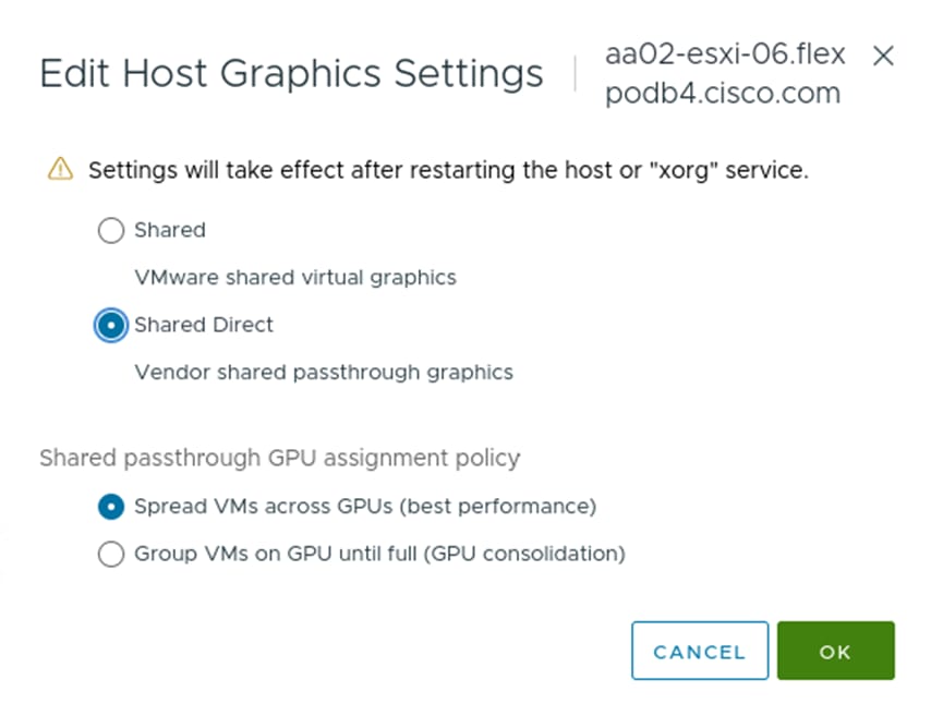
Step 3. Move OCP Worker VMs to hosts that have GPUs.
Note: In this validation lab, we had two ESXi hosts each with two NVIDIA A100-80 GPUs. The initial vGPU setup was two workers each with 2 80G vGPUs and each on one ESXi host. The third worker did not have vGPUs assigned.
Step 4. Migrate the first worker to the first host with GPU(s) and shut down its Guest OS. Once the VM is shut down, right-click it and select Edit Settings. Click ADD NEW DEVICE and select PCI Device. A list of NVIDIA GRID vGPU devices should appear. Select the device appropriate to your deployment and click SELECT.
Step 5. If you are assigning more than one vGPU to this worker, repeat this process to add additional vGPU(s). Click OK to save the Worker configuration. Power on the Worker VM with vGPUs assigned. After power on, make sure the Worker VM is still running on the host that you migrated it to.
Step 6. Repeat this entire procedure to assign vGPUs to all Worker VMs.
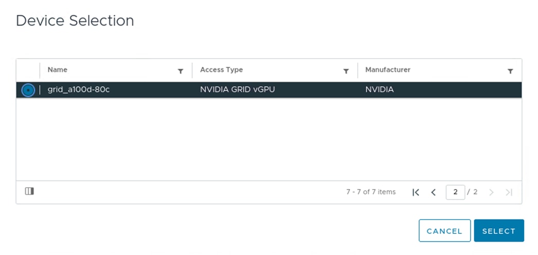
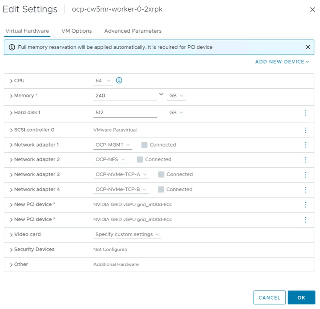
Note: On a single GPU, if more than one device is assigned, all devices must be the same size or from the same profile. Multiple vGPUs can be assigned from a single GPU up to the frame buffer capacity of the GPU.
Step 7. In the Red Hat Openshift Console, select Compute > Nodes. Wait until all three Workers have the Ready status.
Step 8. Skip to Procedure 4.
Procedure 3. Add Physical GPUs to OCP Worker VMs
If you’re mapping the full physical GPUs to OCP workers as PCI devices, complete the following steps.
Step 1. In VMware vCenter, for each VMware ESXi host that has GPU(s) installed, under Inventory select the ESXi host and then select the Configure tab in the center pane. Select Hardware > PCI Devices > ALL PCI DEVICES. Filter the list by Vendor Name and enter NVIDIA. Select all NVIDIA GPUs and choose TOGGLE PASSTHROUGH.
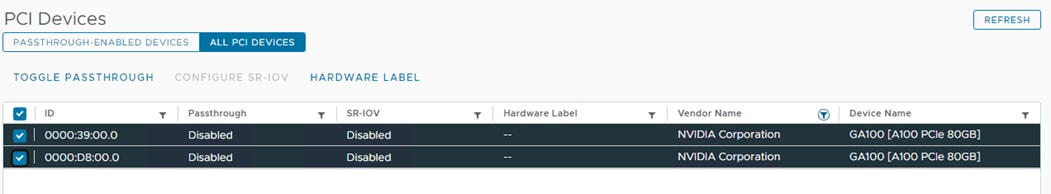
Step 2. Choose PASSTHROUGH-ENABLED DEVICES. The GPUs should now show Passthrough Enabled.
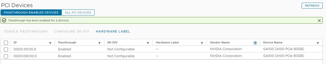
Step 3. Repeat this process for all ESXi hosts that have GPUs. Migrate the first worker to the first host with GPU(s) and shut down its Guest OS. Once the VM is shut down, right-click it and select Edit Settings. Click ADD NEW DEVICE and select PCI Device. A list of NVIDIA GPU devices should appear. Select a Dynamic DirectPath IO device appropriate to your deployment and click SELECT.
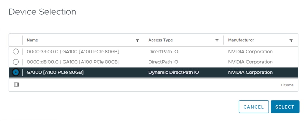
Step 4. If you are assigning more than one GPU to this worker, repeat this process to add additional GPU(s). Click OK to save the Worker configuration. Power on the Worker VM with GPUs assigned. After power on, make sure the Worker VM is still running on the host that you migrated it to.
Step 5. Repeat this entire procedure to assign GPUs to all Worker VMs.
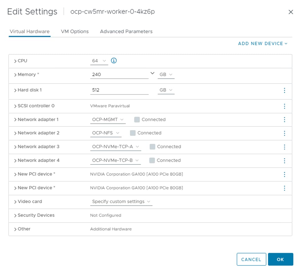
Step 6. In the Red Hat Openshift Console, select Compute > Nodes. Wait until all three workers have the Ready status.
Procedure 4. Install the Node Feature Discovery (NFD) Operator
Using https://docs.nvidia.com/datacenter/cloud-native/openshift/latest/install-nfd.html#install-nfd, install the Red Hat NFD Operator.
Procedure 5. Install the NVIDIA GPU Operator
Step 1. Using https://docs.nvidia.com/datacenter/cloud-native/openshift/latest/install-gpu-ocp.html#install-nvidiagpu, install the NVIDIA GPU Operator.
Step 2. Using https://docs.nvidia.com/datacenter/cloud-native/openshift/latest/nvaie-with-ocp.html, start with Create the NGC secret and continue with Create the ConfigMap for NLS Token. When creating the ConfigMap, make sure the YAML includes “gridd.conf: ‘# empty file’” as the last line. If mapping the full physical GPUs to OCP workers as PCI devices, it is not necessary to create the NGC secret or ConfigMap.
Step 3. Continuing with https://docs.nvidia.com/datacenter/cloud-native/openshift/latest/nvaie-with-ocp.html, create the Cluster Policy Instance. Install driver version 535.129.03 and image vgpu-guest-driver-4-1. If mapping the full physical GPUs to OCP workers as PCI devices, use nvcr.io/nvidia as the repository, 535.129.03 as the version and image driver and do not fill in the NGC secret or ConfigMap.
Note: If mapping vGPUs to OCP, this procedure utilizes the NVAIE vGPU driver container downloaded from the nvcr.io/nvaie registry. If you do not have access to this registry, you can build an image container as specified in https://docs.nvidia.com/datacenter/cloud-native/gpu-operator/latest/install-gpu-operator-vgpu.html.
Procedure 6. Ensure vGPUs are Licensed
If you’re mapping vGPUs to OCP, complete the following steps.
Step 1. On the ocp-installer VM, switch to the nvidia-gpu-operator project:
oc project nvidia-gpu-operator
Step 2. Query the running pods, looking for pods with nvidia-driver-daemonset in the name:
oc get pods
NAME READY STATUS RESTARTS AGE
nvidia-driver-daemonset-414.92.202312191502-0-429vr 2/2 Running 0 7h35m
nvidia-driver-daemonset-414.92.202312191502-0-cx8ks 2/2 Running 0 7h16m
Note: You should see one of these pods for each worker VM that has vGPUs attached.
Step 3. Connect to the bash shell of one of the containers:
oc exec -it nvidia-driver-daemonset-414.92.202312191502-0-429vr – bash
Step 4. Use nvidia-smi to check licensing status:
nvidia-smi -q | grep License
vGPU Software Licensed Product
License Status : Licensed (Expiry: 2024-2-15 2:44:42 GMT)
vGPU Software Licensed Product
License Status : Licensed (Expiry: 2024-2-15 2:44:42 GMT)
Step 5. Repeat this procedure for all nvidia-driver-daemonset containers.
Procedure 7. Enable the vGPU Monitoring Dashboard
Step 1. Using https://docs.nvidia.com/datacenter/cloud-native/openshift/latest/enable-gpu-monitoring-dashboard.html, enable to GPU Monitoring Dashboard to monitor vGPUs in the Openshift Web-Console.
Note: Notice that GPU hardware parameters such as Temperature and Power are not available with vGPUs but are available if mapping the full physical GPUs to OCP workers as PCI devices.
Procedure 8. Enable GPU Monitoring in VMware vCenter
If you’re mapping vGPUs to OCP, complete the following steps.
Step 1. In VMware vCenter, select an ESXi host that has GPU(s) installed and select the Monitor tab in the center pane. Select Performance > Advanced.
Step 2. Click Chart Options. In the list on the left under Chart Metrics, select GPU. Select up to two counters (Temperature and Utilization recommended) and make sure all Target Objects are selected.
Step 3. Click SAVE OPTIONS AS. Enter GPU for the Chart options name and click OK.
Step 4. Click OK to view the chart. This chart is now available on all ESXi hosts with GPUs.
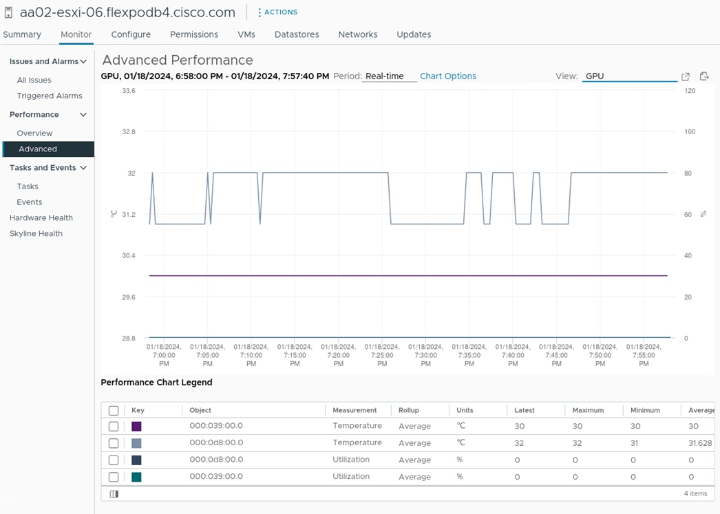
Astra Trident is an open-source, fully supported storage orchestrator for containers and Kubernetes distributions. It was designed to help meet the containerized applications’ persistence demands using industry-standard interfaces, such as the Container Storage Interface (CSI). With Astra Trident, microservices and containerized applications can take advantage of enterprise-class storage services provided by NetApp portfolio of storage systems. More information about Trident can be found here: NetApp Trident Documentation. NetApp Astra Trident can be installed via different methods. In this solution we will discuss using helm.
Note: The Infrastructure SVM created earlier (OCP-SVM) can be used for Trident backend.
Note: In this solution, we validated NetApp Trident with ontap-nas driver and ONTAP NAS FlexGroup driver using the NFS protocol. We also validated ontap-san driver for NVMe/TCP.
Note: For information to understand the storage platform preparation for Trident, go to: https://docs.netapp.com/us-en/trident/trident-reco/storage-config-best-practices.html
Prerequisites
Note: You need full support and access to a Kubernetes cluster min. version 1.23
Procedure 1. Install Helm version
Step 1. Download the Helm binary and add it to your path:
curl -L https://mirror.openshift.com/pub/openshift-v4/clients/helm/latest/helm-linux-amd64 -o /usr/local/bin/helm
Step 2. Make the binary file executable:
chmod +x /usr/local/bin/helm
Step 3. Check the installed version:
helm version
Procedure 2. Trident installation using Helm
Step 1. Download Trident software from GitHub and untar the .gz file to obtain the trident-installer folder:
# wget https://github.com/NetApp/trident/releases/download/v23.10.0/trident-installer-23.10.0.tar.gz
Saving to: ‘trident-installer-23.10.0.tar.gz’
# tar –xvf trident-installer-23.10.0.tar.gz
# cd trident-installer/helm
Step 2. Create Trident namespace:
oc create namespace trident
Step 3. Install using the helm:
helm install ocp-trident trident-operator-23.10.0.tgz –n trident
Step 4. Check the pods output after installation:
# oc get pods -n trident
NAME READY STATUS RESTARTS AGE
trident-controller-7ddc988d7-vbxlp 6/6 Running 0 4m18s
trident-node-linux-525mk 2/2 Running 0 4m18s
trident-node-linux-cv7xs 2/2 Running 0 4m18s
trident-node-linux-f22qk 2/2 Running 0 4m18s
trident-node-linux-fk2gs 2/2 Running 0 4m18s
trident-node-linux-nfwsr 2/2 Running 0 4m18s
trident-node-linux-q7h57 2/2 Running 0 4m18s
trident-operator-5464f56594-qd5wp 1/1 Running 0 4m36s
Note: If the Astra Trident deployment fails and does not bring up the pods to Running state, use the tridentctl logs -l all -n trident command for debugging.
Note: Before configuring the backend that Trident needs to use for user apps, go to: https://docs.netapp.com/us-en/trident/trident-reference/objects.html#kubernetes-customresourcedefinition-objects to understand the storage environment parameters and its usage in Trident.
Procedure 3. Prepare the Worker Node
Step 1. All the worker nodes in the Kubernetes cluster need to be able to mount the volumes that you have provisioned for your pods. For the ontap-nas driver (NAS backend), workers need the NFS tools and for the ontap-san driver for NVMe/TCP, workers need the NVMe tools.
Step 2. Recent versions of RedHat CoreOS have the tools installed by default. Make sure that the utilities are installed and running on all worker nodes:
rpm -qa | grep nfs-utils
systemctl status nfs-client.target
rpm -qa | grep nvme-cli
Procedure 4. Configure the Storage Backend in Trident
Step 1. Configure the connection to the SVM on the NetApp storage array created for the OCP installation. For more options regarding storage backend configuration, refer to https://docs.netapp.com/us-en/trident/trident-use/backends.html
Step 2. Backend definition for ONTAP NAS driver:
# cat << EOF > backend_NFS.json
{
"version": 1,
"storageDriverName": "ontap-nas",
"backendName": "ocp-nas-backend",
"managementLIF": "10.102.2.30",
"dataLIF": "192.168.52.31",
"svm": "OCP-SVM",
"username": "vsadmin",
"password": "********",
"defaults": {
"spaceReserve": "volume",
"exportPolicy": "default",
"snapshotPolicy": "default",
"snapshotReserve": "10"
}
}
# cat << EOF > backend_NFS_flexgroup.json
{
"version": 1,
"storageDriverName": "ontap-nas-flexgroup",
"backendName": "ocp-nas-flexgroup",
"managementLIF": "10.102.2.30",
"dataLIF": "192.168.52.31",
"svm": "OCP-SVM",
"username": "vsadmin",
"password": "********",
"defaults": {
"spaceReserve": "volume",
"exportPolicy": "default",
"snapshotPolicy": "default",
"snapshotReserve": "10"
}
}
For more information about configuring ONTAP NAS driver and ONTAP NAS FlexGroup driver for NFS in Trident, go to: https://docs.netapp.com/us-en/trident/trident-use/ontap-nas.html
Step 3. Backend definition for ONTAP SAN drivers:
# cat << EOF > backend_NVME.yaml
---
version: 1
backendName: ocp-nvme-backend
storageDriverName: ontap-san
managementLIF: 10.102.2.30
svm: OCP-SVM
username: vsadmin
password: *********
sanType: nvme
useREST: true
For more information about configuring ONTAP SAN driver for NVMe/TCP in Trident, go to: https://docs.netapp.com/us-en/trident/trident-use/ontap-san.html
Step 4. Activate the backend storage configuration:
tridentctl -n trident create backend -f backend_NFS.json
tridentctl -n trident create backend -f backend_NFS_flexgroup.json
tridentctl -n trident create backend -f backend_NVME.yaml
tridentctl -n trident get backend
+-------------------+---------------------+--------------------------------------+--------+------------+---------+
| NAME | STORAGE DRIVER | UUID | STATE | USER-STATE | VOLUMES |
+-------------------+---------------------+--------------------------------------+--------+------------+---------+
| ocp-nas-backend | ontap-nas | e4595547-96b9-4a2c-84f2-ea16a237ee87 | online | normal | 1 |
| ocp-nvme-backend | ontap-san | 272dcbab-7191-4b25-a20b-d09a4b395f80 | online | normal | 1 |
| ocp-nas-flexgroup | ontap-nas-flexgroup | e9d2c647-e6f3-470f-a033-4801f564e61f | online | normal | 1 |
+-------------------+---------------------+--------------------------------------+--------+------------+---------+
Step 5. Configure a storage class based on the storage backend created earlier and make it the default:
# cat << EOF > storage-class-csi.yaml
apiVersion: storage.k8s.io/v1
kind: StorageClass
metadata:
name: ontap-nas-sc
annotations:
storageclass.kubernetes.io/is-default-class: "true"
provisioner: csi.trident.netapp.io
parameters:
backendType: "ontap-nas"
provisioningType: "thin"
snapshots: "true"
allowVolumeExpansion: true
# cat storage-class-flexgroup.yaml
---
apiVersion: storage.k8s.io/v1
kind: StorageClass
metadata:
name: ontap-nas-flexgroup
annotations:
storageclass.kubernetes.io/is-default-class: "true"
provisioner: csi.trident.netapp.io
parameters:
backendType: "ontap-nas-flexgroup"
provisioningType: "thin"
snapshots: "true"
allowVolumeExpansion: true
Step 6. storage class for ONTAP SAN backend:
# cat storage-class-NVMe.yaml
---
apiVersion: storage.k8s.io/v1
kind: StorageClass
metadata:
name: ontap-nvme-test
parameters:
backendType: "ontap-san"
provisioningType: "thin"
snapshots: "true"
provisioner: csi.trident.netapp
Step 7. Create a storage class:
# oc create -f storage-class-csi.yaml
# oc create -f storage-class-flexgroup.yaml
# oc create -f storage-class-NVMe.yaml
oc get sc
NAME PROVISIONER RECLAIMPOLICY VOLUMEBINDINGMODE ALLOWVOLUMEEXPANSION AGE
ontap-nas-flexgroup (default) csi.trident.netapp.io Delete Immediate false 154m
ontap-nas-sc (default) csi.trident.netapp.io Delete Immediate false 6h8m
ontap-nvme csi.trident.netapp.io Delete Immediate false 3h11m
tridentctl get storageclass -n trident
+---------------------+
| NAME |
+---------------------+
| ontap-nas-sc |
| ontap-nvme |
| ontap-nas-flexgroup |
+---------------------+
Step 8. Create Volume Snapshot class for the OCP cluster.
# cat volumesnapshot-class-csi.yaml
---
apiVersion: snapshot.storage.k8s.io/v1
kind: VolumeSnapshotClass
metadata:
name: csi-snapclass
driver: csi.trident.netapp.io
deletionPolicy: Delete
# oc create -f volumesnapshot-class-csi.yaml
volumesnapshotclass.snapshot.storage.k8s.io/csi-snapclass created
Step 9. Test the storage connection by creating a Persistent Volume Claim (PVC):
# cat pvc-basic.yaml
---
kind: PersistentVolumeClaim
apiVersion: v1
metadata:
name: test
spec:
accessModes:
- ReadWriteOnce
resources:
requests:
storage: 1Gi
storageClassName: ontap-nas-sc
# cat pvc-flexgroup.yaml
---
kind: PersistentVolumeClaim
apiVersion: v1
metadata:
name: flexgroup-try
spec:
accessModes:
- ReadWriteOnce
resources:
requests:
storage: 900Gi
storageClassName: ontap-nas-flexgroup
For more information about creating PVC for custom applications, go to: KubernetesPersistentVolumeClaimObjects
Step 10. PVC for ONTAP SAN:
# cat pvc-nvme.yaml
---
apiVersion: v1
kind: PersistentVolumeClaim
metadata:
name: nvme-pvc
spec:
accessModes:
- ReadWriteOnce
resources:
requests:
storage: 700Gi
storageClassName: ontap-nvme
Step 11. Create a PVC:
# oc create -f pvc-basic.yaml
# oc create -f pvc-flexgroup.yaml
# oc create -f pvc-nvme.yaml
#
# [root@ocp-installer trident-installer]# oc get pvc
NAME STATUS VOLUME CAPACITY ACCESS MODES STORAGECLASS AGE
flexgroup-try Bound pvc-00081a3c-9a95-4e5c-8823-6433ec348d04 900Gi RWO ontap-nas-flexgroup 178m
nvme-pvc Bound pvc-65466967-7da9-4d46-b3da-13d71f044621 700Gi RWO ontap-nvme 3h34m
test Bound pvc-2a05bf9e-e0a4-4702-a6e7-7dee2ca471f5 1Gi RWO ontap-nas-sc 6h36m
[root@ocp-installer trident-installer]# tridentctl get volume -n trident
+------------------------------------------+---------+---------------------+----------+--------------------------------------+-------+---------+
| NAME | SIZE | STORAGE CLASS | PROTOCOL | BACKEND UUID | STATE | MANAGED |
+------------------------------------------+---------+---------------------+----------+--------------------------------------+-------+---------+
| pvc-00081a3c-9a95-4e5c-8823-6433ec348d04 | 900 GiB | ontap-nas-flexgroup | file | e9d2c647-e6f3-470f-a033-4801f564e61f | | true |
| pvc-2a05bf9e-e0a4-4702-a6e7-7dee2ca471f5 | 1.0 GiB | ontap-nas-sc | file | e4595547-96b9-4a2c-84f2-ea16a237ee87 | | true |
| pvc-65466967-7da9-4d46-b3da-13d71f044621 | 700 GiB | ontap-nvme | block | 272dcbab-7191-4b25-a20b-d09a4b395f80 | | true |
+------------------------------------------+---------+---------------------+----------+--------------------------------------+-------+---------+
Step 12. Verify that the PVC volume is created on the ONTAP storage backend.
AA02-A800::> volume show -vserver OCP-SVM
Vserver Volume Aggregate State Type Size Available Used%
--------- ------------ ------------ ---------- ---- ---------- ---------- -----
OCP-SVM trident_pvc_00081a3c_9a95_4e5c_8823_6433ec348d04
- online RW 1000GB 896.0GB 0%
OCP-SVM trident_pvc_2a05bf9e_e0a4_4702_a6e7_7dee2ca471f5
AA02_A800_02_NVME_SSD_1
online RW 1.11GB 1023MB 0%
OCP-SVM trident_pvc_65466967_7da9_4d46_b3da_13d71f044621
AA02_A800_02_NVME_SSD_1
online RW 770GB 770.0GB 0%
This completes the NetApp Astra Trident installation and configuration.
The toolkit is currently compatible with Kubernetes versions 1.17 and above, and OpenShift versions 4.4 and above.
The toolkit is currently compatible with Trident versions 20.07 and above. Additionally, the toolkit is compatible with the following Trident backend types:
● ontap-nas
● ontap-nas-flexgroup
● gcp-cvs
● azure-netapp-files
More operations and capabilities about NetApp DataOps Toolkit are available and documented here: https://github.com/NetApp/netapp-data-science-toolkit
Prerequisites
The NetApp DataOps Toolkit for Kubernetes requires that Python 3.8 or above be installed on the local host. Additionally, the toolkit requires that pip for Python3 be installed on the local host. For more details regarding pip, including installation instructions, refer to the pip documentation.
Procedure 1. Installation
Step 1. To install the NetApp DataOps Toolkit for Kubernetes, run the following command:
python3 -m pip install netapp-dataops-k8s
NetApp DataOps Toolkit is used to create jupyterlab, clone jupyterlab, create a snapshot for a JupyterLab workspace, and so on.
Note: We used NetApp DataOps Toolkit to create Jupyter notebook in this solution. For more information, go to: Create a new JupyterLab workspace.
Generative Inferencing AI Model Deployment and Results
This chapter contains the following:
● NVIDIA NeMo Framework Inference
● PyTorch
● Resnet34
NVIDIA NeMo Framework Inference
NVIDIA NeMo™ is an end-to-end, cloud-native framework to build, customize, and deploy generative AI models anywhere. It includes training and inferencing frameworks, guardrail toolkits, data curation tools, and pretrained models, offering enterprises an easy, cost-effective, and fast way to adopt generative AI.
Note: In this validation, NVIDIA NeMo inferencing, which uses Triton Inferencing Server, was implemented along with four AI models.
| Model |
Location |
Processing |
| Nemo GPT 2B |
None |
|
| Nemotron-3-8B-QA-4k |
None |
|
| Llama-2-7B-Chat |
*Converted from huggingface to nemo format using NeMo training container. |
|
| Llama-2-13B-Chat |
*Converted from huggingface to nemo format using NeMo training container. |
|
| Llama-2-70B-Chat |
*Converted from huggingface to nemo format using NeMo training container. |
|
| Llama-2-70B-SteerLM-Chat |
.nemo file built using instructions on model card. |
* See https://docs.nvidia.com/nemo-framework/user-guide/latest/playbooks/llama2peft.html#optional-convert-llama2-from-huggingface-format-to-nemo-format for the conversion procedure. The NeMo training container can be deployed with a modified version of the deployment.yaml specified below.
Note: To convert the Llama-2-70B-Chat model from huggingface to nemo format required a worker VM with more than 535GB of RAM (our worker VM had 960GB RAM on a server with 1TB RAM) and required 300GB of shared memory.
Deployment
To deploy the NeMo Inferencing container, a nemo project was created in OCP to create a namespace for running NeMo. A persistent volume claim (PVC) was first created using the Astra Trident NFS StorageClass (ontap-nas-sc).
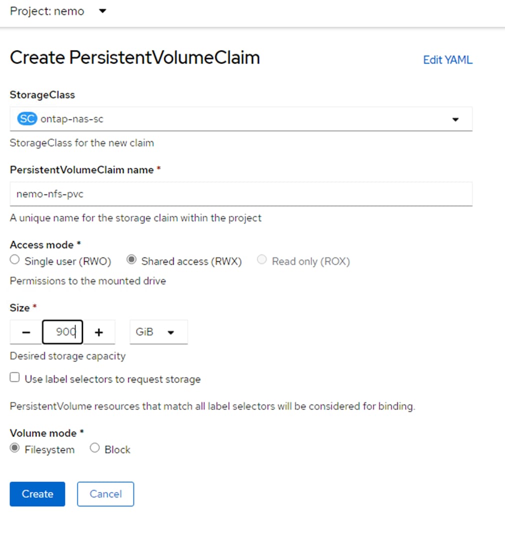
Once the PVC is created, the following deployment.yaml can be used to deploy a NeMo container:
apiVersion: apps/v1
kind: Deployment
metadata:
name: nemo-framework-inference-deployment
spec:
strategy:
type: Recreate
# Replicas controls the number of instances of the Pod to maintain running at all times
replicas: 1
selector:
matchLabels:
app: nemo-framework-inference
template:
metadata:
labels:
app: nemo-framework-inference
name: nemo-framework-inference-pod
spec:
volumes:
- name: model-repository
persistentVolumeClaim:
claimName: nemo-nfs-pvc
- name: dshm
emptyDir:
medium: Memory
sizeLimit: 96Gi # Use 300Gi for Llama-2-70B
containers:
- name: nemo-framework-inference-container
image: quay.io/jogeorg2/nemofw-inference:23.10_fix_v2
command: [ "/bin/bash", "-c", "--" ]
args: [ "while true; do sleep 30; done;" ]
volumeMounts:
- name: model-repository
mountPath: /opt/checkpoints
- mountPath: /dev/shm
name: dshm
ports:
- name: nemo
containerPort: 8000
resources:
limits:
nvidia.com/gpu: 2 # requesting 2 GPUs
Notice the PVC attachment to /opt/checkpoints. This PVC must be large enough to hold all models that will be run. Also notice that in this case, the PVC was created with Shared Access, meaning more than one instance of this container could be attaching to the same model-repository. This allows more than one container instance to read model data simultaneously, but the names must be adjusted when writing back to the TensorRT temp folder. This validation also found that the NeMo Inference container must be run as root in the namespace.
Once a container is deployed, the “.nemo” model files can be copied to the model-repository mounted on persistent storage at /opt/checkpoints. In this example, NFS storage was mapped and used. To see the NFS mount for persistent storage, run the following from within the container (partial command output shown).
df -h
Filesystem Size Used Avail Use% Mounted on
overlay 512G 110G 402G 22% /
tmpfs 64M 0 64M 0% /dev
tmpfs 48G 135M 48G 1% /etc/hostname
192.168.52.31:/trident_pvc_2936a6cd_beb6_466c_91a0_d92ddff457ad 900G 575G 326G 64% /opt/checkpoints
tmpfs 96G 0 96G 0% /dev/shm
To run NeMo Triton Inferencing server with a model, such as Llama 2 13B, run the following from the /opt/NeMo directory within the container.
python scripts/deploy/deploy_triton.py --nemo_checkpoint /opt/checkpoints/Llama-2-13b-chat-hf.nemo --model_type="llama" --triton_model_name Llama-2-13b-chat-hf --triton_model_repository /opt/checkpoints/trt_llm_model_dir_13b --triton_http_address 0.0.0.0 --triton_port 8000 --num_gpus 2 --max_input_len 3072 --max_output_len 1024 --max_batch_size 8 &
Note: For the NeMo models, the model_type is gptnext.
Once the model is loaded, the following python script can be run from within the container to perform an inference query.
from nemo.deploy import NemoQuery
nq = NemoQuery(url="localhost:8000", model_name="Llama-2-13b-chat-hf")
output = nq.query_llm(prompts=["What is the capital of the United States?"], max_output_token=1024, top_k=1, top_p=0.0, temperature=1.0)
print(output)
The result of the query is:
[['Answer: The capital of the United States is Washington, D.C. (District of Columbia).']]
Results
The NeMo Inference container contains a python benchmark script that was run for each of the four models utilizing either one or two vGPUs with results in the following two tables. Note that more data was generated but only the first and last result sets were documented. As the models get larger, the benefit of the second GPU is shown. To launch the benchmark script for the Nemotron 3 8B QA model, run the following from the /opt/NeMo directory within the container.
python scripts/deploy/benchmark.py --nemo_checkpoint /opt/checkpoints/Nemotron-3-8B-QA-4k.nemo --model_type="gptnext" --triton_model_name Nemotron-3-8B-QA-4k -tlf /opt/checkpoints/trt_llm_model_dir_8b -ng 2 -mil 2048 -mol 300 -mbs 10 -nr 50 --out_jsonl="/opt/checkpoints/Nemotron-3-8B-QA-4k.nemo.json"
Note: It is recommended to delete the trt_llm_model_dir directory between benchmark runs.
The results listed in the following tables are shown in the terminal window as the benchmark script is running.
Table 6. NeMo Framework Benchmark Results: Input Tokens Length: 128 and Output Tokens Length: 20
| Model |
Batch Size |
Average Latency (ms) |
Average Throughput (sentence/s) |
||
|
|
1 GPU |
2 GPUs |
1 GPU |
2 GPUs |
|
| Llama-2-7B-Chat |
1 |
151.341 |
132.611 |
6.608 |
7.541 |
| 2 |
156.135 |
143.724 |
12.809 |
13.916 |
|
| 4 |
181.916 |
175.997 |
21.988 |
22.728 |
|
| 8 |
231.947 |
254.829 |
34.491 |
31.394 |
|
| Llama-2-13B-Chat |
1 |
445.038 |
325.023 |
2.247 |
3.077 |
| 2 |
464.125 |
357.096 |
4.309 |
5.601 |
|
| 4 |
512.184 |
436.986 |
7.81 |
9.154 |
|
| 8 |
604.336 |
551.75 |
13.238 |
14.499 |
|
| NeMo GPT 2B |
1 |
111.042 |
115.757 |
9.006 |
8.639 |
| 2 |
111.308 |
124.159 |
17.968 |
16.108 |
|
| 4 |
117.547 |
138.645 |
34.029 |
28.851 |
|
| 8 |
135.265 |
179.492 |
59.143 |
44.57 |
|
| Nemotron 3 8B QA |
1 |
268.788 |
212.526 |
3.72 |
4.705 |
| 2 |
274.21 |
226.204 |
7.294 |
8.842 |
|
| 4 |
301.054 |
265.123 |
13.287 |
15.087 |
|
| 8 |
350.81 |
356.066 |
22.804 |
22.468 |
|
| Llama-2-70B-Chat* |
1 |
|
1177.303 |
|
0.849 |
| 2 |
|
1289.825 |
|
1.551 |
|
| 4 |
|
1544.36 |
|
2.59 |
|
| 8 |
|
1955.497 |
|
4.091 |
|
| Llama-2-70B-SteerLM-Chat* |
1 |
|
1181.178 |
|
0.847 |
| 2 |
|
1291.574 |
|
1.548 |
|
| 4 |
|
1547.5 |
|
2.585 |
|
| 8 |
|
1955.021 |
|
4.092 |
|
*The Llama-2-70B models only ran on NeMo when the full physical GPUs were mapped to OCP, and with 2 GPUs each with 80GB frame buffer, a worker with 480GB RAM, and 300GB shared memory.
Table 7. NeMo Framework Benchmark Results: Input Tokens Length: 2048 and Output Tokens Length: 300
| Model |
Batch Size |
Average Latency (ms) |
Average Throughput (sentence/s) |
||
|
|
1 GPU |
2 GPUs |
1 GPU |
2 GPUs |
|
| Llama-2-7B-Chat |
1 |
4262.242 |
3416.611 |
0.235 |
0.293 |
| 2 |
4506.674 |
3736.085 |
0.444 |
0.535 |
|
| 4 |
5516.922 |
4389.155 |
0.725 |
0.911 |
|
| 8 |
7026.116 |
6341.28 |
1.139 |
1.262 |
|
| Llama-2-13B-Chat |
1 |
7198.969 |
5182.613 |
0.139 |
0.193 |
| 2 |
7802.567 |
5794.564 |
0.256 |
0.345 |
|
| 4 |
9288.796 |
7207.308 |
0.431 |
0.555 |
|
| 8 |
11851.359 |
9662.157 |
0.675 |
0.828 |
|
| NeMo GPT 2B |
1 |
1814.402 |
1813.078 |
0.551 |
0.552 |
| 2 |
1888.723 |
1988.144 |
1.059 |
1.006 |
|
| 4 |
2044.045 |
2245.199 |
1.957 |
1.782 |
|
| 8 |
2735.752 |
2902.535 |
2.924 |
2.756 |
|
| Nemotron 3 8B QA |
1 |
4392.053 |
3372.163 |
0.228 |
0.297 |
| 2 |
4621.118 |
3677.279 |
0.433 |
0.544 |
|
| 4 |
5605.302 |
4334.843 |
0.714 |
0.923 |
|
| 8 |
7071.629 |
6269.211 |
1.131 |
1.276 |
|
| Llama-2-70B-Chat* |
1 |
|
18810.341 |
|
0.053 |
| 2 |
|
20637.673 |
|
0.097 |
|
| 4 |
|
25515.891 |
|
0.157 |
|
| 8 |
|
Out of Memory |
|
Out of Memory |
|
| Llama-2-70B-SteerLM-Chat* |
1 |
|
18827.029 |
|
0.053 |
| 2 |
|
20599.33 |
|
0.097 |
|
| 4 |
|
25535.6 |
|
0.157 |
|
| 8 |
|
Out of Memory |
|
Out of Memory |
|
*The Llama-2-70B models only ran on NeMo when the full physical GPUs were mapped to OCP, and with 2 GPUs each with 80GB frame buffer, a worker with 480GB RAM, and 300GB shared memory.
The following figures show the NVIDIA DGCM Exporter Dashboard from the OCP Console. The Llama 2 13B Llama-2-13b-chat-hf.nemo file has a size of approximately 52 GB, which roughly corresponds to usage in the figure below with single GPU usage. However, more than 70GB is used in each GPU with 2 GPUs. This usage was less with the smaller models.
Figure 19. Llama 2 13B Single GPU Benchmark Framebuffer Usage
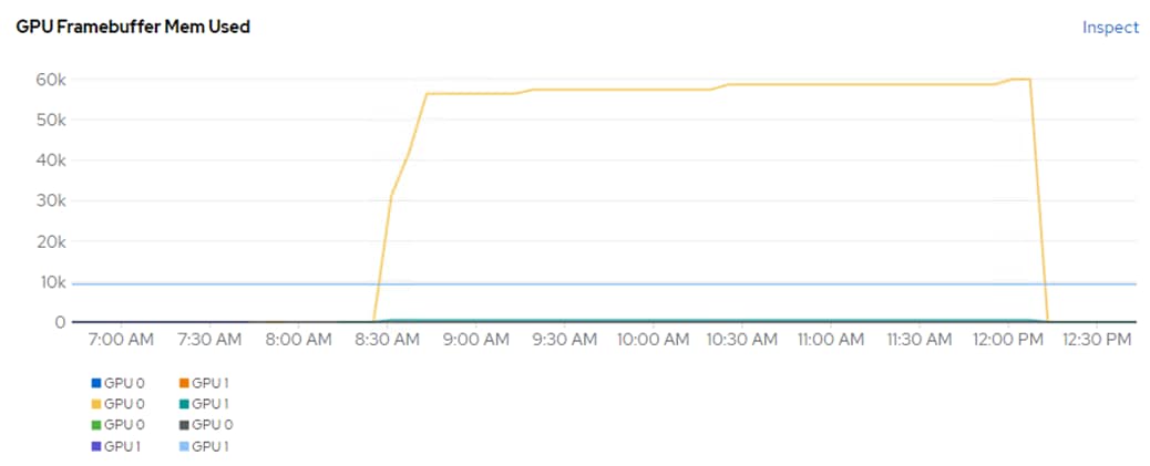
Figure 20. Llama 2 13B 2 GPU Benchmark Framebuffer Usage (Starting Just Before 1:00PM)

Power usage was also monitored while running these models. Each NVIDIA A100-80 GPU had a maximum power consumption of approximately 300W. Using 2 GPUs had 300W more power consumption, but did produce better performance, especially with the larger models.
Text Generation Inference (TGI) is a toolkit for deploying and serving Large Language Models (LLMs). TGI enables high-performance text generation for the most popular open-source LLMs, including Llama, Falcon, StarCoder, BLOOM, GPT-NeoX, and T5.
Figure 21. TGI Model Representation
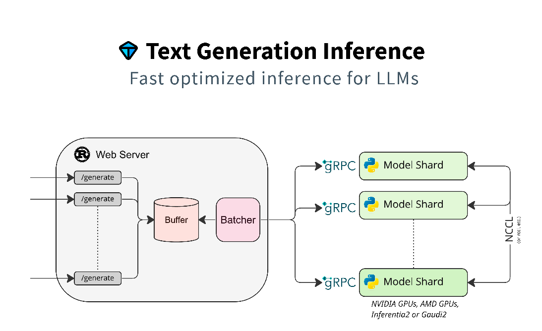
The models run on TGI are listed in Table 8.
Table 8. AI Inferencing Models Run on TGI
| Model |
Download Location |
| BLOOM-7B |
|
| Google FLAN-T5 XL 2.85B |
|
| Google FLAN-T5 XXL 11.3B |
|
| GALACTICA 30B |
|
| GPT-NeoX-20B |
|
| OPT-2.7B |
|
| MPT-30B |
|
| Falcon-40B |
|
| Mistral-7B-Instruct-v0.1 |
|
| Code Llama 34B-Base |
|
| Code Llama 70B-Base |
|
| Llama-2-70B-Chat-HF |
|
| Defog SQLCoder-15B |
|
| Defog SQLCoder-34B |
Deployment
To deploy the TGI container, a “tgi” project was created in OCP to create a namespace for running TGI. A persistent volume claim (PVC) was first created using the Astra Trident NFS FlexGroup StorageClass (ontap-nas-flexgroup).
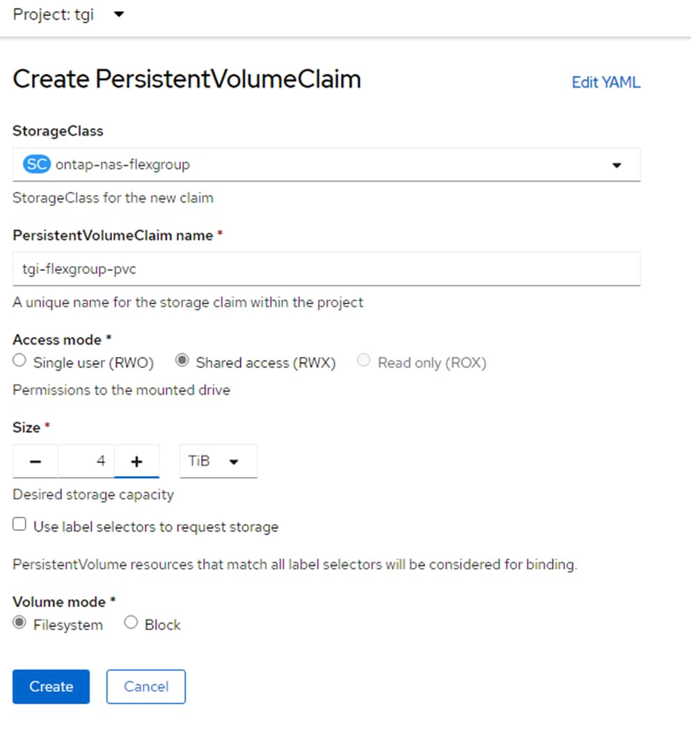
Once the PVC is created, the following yaml can be used to deploy a TGI container:
apiVersion: apps/v1
kind: Deployment
metadata:
name: tgi-deployment
spec:
strategy:
type: Recreate
replicas: 1
selector:
matchLabels:
app: tgi
template:
metadata:
labels:
app: tgi
name: tgi-pod
spec:
volumes:
- name: tgi
persistentVolumeClaim:
claimName: tgi-flexgroup-pvc
- name: shm
emptyDir:
medium: Memory
sizeLimit: 10Gi
restartPolicy: Always
containers:
- name: tgi-container
image: ghcr.io/huggingface/text-generation-inference
command: [ "/bin/bash", "-c", "--" ]
args: [ "while true; do sleep 30; done;" ]
volumeMounts:
- name: tgi
mountPath: /data
- name: shm
mountPath: /dev/shm
resources:
limits:
nvidia.com/gpu: 2
Notice that the container is being pulled from the HuggingFace registry. Also notice the PVC attachment to /data. This PVC must be large enough to hold all models that will be run. Also notice that in this case, the PVC was created with Shared Access, meaning more than one instance of this container could be attaching to the same model-repository. This allows more than one container instance to read model data simultaneously. This validation also found that the TGI Inference container must be run as root in the namespace.
Using an NFS-based Storage Class with SharedAccess allows the PV created from the PVC to be mounted to the ocp-installer VM. An MTU 9000 network interface must be added to the VM in the OCP-NFS port group on VMware vDS0. Once this network interface is in place, the PV can be mounted and the ocp-installer VM can be used to directly pull the TGI-supported models and place them in the PV.
The following service file can also be applied to make the TGI server accessible:
kind: Service
apiVersion: v1
metadata:
name: tgi-svc
spec:
type: NodePort
selector:
app: tgi
ports:
- protocol: TCP
nodePort:
port: 8080
targetPort: 8080
When this file is applied within the tgi project or namespace, a nodePort will automatically get assigned. This TCP port can be determined by running:
oc get svc
NAME TYPE CLUSTER-IP EXTERNAL-IP PORT(S) AGE
tgi-svc NodePort 172.30.170.1 <none> 8080:31234/TCP 6m49s
Then after TGI is up and running with the first command below under Results, inferencing can be done from a machine outside the OCP cluster using one of the master or worker VM’s OCP-MGMT IPs or the *.apps IP as shown:
[admin@ocp-installer tgi]$ curl 10.102.2.201:31234/generate -X POST -d '{"inputs":"What is the capital of South Dakota?","parameters":{"max_new_tokens":50}}' -H 'Content-Type: application/json'
{"generated_text":"\nThe capital of South Dakota is Pierre."}
Results
The TGI container contains a python benchmark script that was run for each of the models utilizing two vGPUs with results in the following table. Each model was first loaded from the container with:
text-generation-launcher --model-id /data/<model-dir> --json-output --sharded=true --num-shard=2 --trust-remote-code --hostname 0.0.0.0 -p 8080
Then, from another window in the container:
text-generation-benchmark --tokenizer-name=/data/<model-dir> --batch-size=<batch-size> --runs=100 --warmups=10
Table 9. TGI Benchmark Results
| Model |
Batch Size |
Prefill Latency (ms) |
Decode Token Latency (ms) |
Decode Total Latency (ms) |
Prefill Throughput (token/s) |
Decode Throughput (token/s) |
| BLOOM 7B |
1 |
15.08 |
14.51 |
101.57 |
70.36 |
70.48 |
| 2 |
16.82 |
14.80 |
103.62 |
124.96 |
137.82 |
|
| 4 |
19.19 |
15.67 |
109.68 |
208.52 |
261.15 |
|
| 8 |
26.73 |
17.16 |
120.10 |
299.39 |
474.25 |
|
| Google FLAN-T5 XL 2.85B |
1 |
43.51 |
26.03 |
182.21 |
23.21 |
38.61 |
| 2 |
46.98 |
28.18 |
197.28 |
42.97 |
71.22 |
|
| 4 |
49.87 |
29.84 |
208.85 |
80.67 |
134.41 |
|
| 8 |
54.43 |
32.11 |
224.75 |
148.27 |
249.72 |
|
| Google FLAN-T5 XXL 11.3B |
1 |
44.69 |
26.32 |
184.24 |
22.66 |
38.18 |
| 2 |
47.63 |
28.34 |
198.38 |
42.40 |
70.89 |
|
| 4 |
51.69 |
29.57 |
207.02 |
78.47 |
135.73 |
|
| 8 |
52.36 |
30.59 |
214.15 |
154.33 |
262.47 |
|
| GALACTICA 30B |
1 |
38.92 |
31.06 |
217.46 |
26.10 |
32.28 |
| 2 |
40.34 |
31.69 |
221.83 |
49.92 |
63.34 |
|
| 4 |
45.83 |
34.38 |
240.68 |
87.68 |
116.60 |
|
| 8 |
59.66 |
37.54 |
262.79 |
134.39 |
213.45 |
|
| GPT-NeoX-20B |
1 |
21.57 |
18.64 |
130.50 |
46.92 |
53.86 |
| 2 |
23.33 |
19.10 |
133.72 |
87.54 |
105.11 |
|
| 4 |
24.90 |
20.27 |
141.91 |
162.19 |
198.15 |
|
| 8 |
31.05 |
20.88 |
146.13 |
259.15 |
384.31 |
|
| MPT-30B |
1 |
36.19 |
29.21 |
204.46 |
28.18 |
34.38 |
| 2 |
39.40 |
30.63 |
214.39 |
51.40 |
65.57 |
|
| 4 |
44.46 |
33.20 |
232.38 |
90.48 |
120.85 |
|
| 8 |
57.76 |
35.41 |
247.85 |
138.98 |
226.45 |
|
| Falcon-40B |
1 |
39.09 |
34.01 |
238.07 |
25.68 |
29.44 |
| 2 |
41.04 |
34.96 |
244.73 |
48.91 |
57.26 |
|
| 4 |
47.28 |
36.70 |
256.94 |
86.66 |
109.09 |
|
| 8 |
55.35 |
37.67 |
263.67 |
144.61 |
212.49 |
|
| Mistral-7B-Instruct-v0.1 |
1 |
44.32 |
24.35 |
170.47 |
30.15 |
44.48 |
| 2 |
44.91 |
24.68 |
172.76 |
55.39 |
86.71 |
|
| 4 |
61.20 |
24.70 |
172.92 |
88.26 |
172.72 |
|
| 8 |
56.50 |
25.20 |
176.42 |
167.70 |
334.30 |
|
| Code Llama 34B-Base |
1 |
35.28 |
29.27 |
204.88 |
28.76 |
34.39 |
| 2 |
38.38 |
30.45 |
213.15 |
52.78 |
65.99 |
|
| 4 |
43.23 |
32.94 |
230.59 |
93.62 |
122.03 |
|
| 8 |
56.72 |
34.14 |
238.97 |
141.18 |
235.06 |
|
| Code Llama 70B-Base |
1 |
63.61 |
53.72 |
376.08 |
15.77 |
18.62 |
| 2 |
69.05 |
56.34 |
394.39 |
28.98 |
35.52 |
|
| 4 |
78.19 |
60.43 |
423.03 |
51.29 |
66.26 |
|
| 8 |
101.31 |
62.29 |
436.03 |
78.96 |
128.48 |
|
| Llama-2-70B-Chat-HF |
1 |
66.35 |
55.99 |
391.91 |
15.24 |
17.91 |
| 2 |
72.69 |
57.22 |
400.53 |
28.13 |
34.99 |
|
| 4 |
77.64 |
61.92 |
433.48 |
51.52 |
64.71 |
|
| 8 |
103.77 |
62.70 |
438.88 |
77.20 |
127.65 |
|
| Defog SQLCoder-15B |
1 |
62.75 |
25.00 |
174.97 |
21.45 |
42.28 |
| 2 |
59.75 |
26.22 |
183.52 |
40.59 |
79.94 |
|
| 4 |
55.82 |
27.63 |
193.44 |
81.79 |
149.73 |
|
| 8 |
68.04 |
26.77 |
187.36 |
132.36 |
308.88 |
|
| Defog SQLCoder-34B |
1 |
35.18 |
28.79 |
201.57 |
28.84 |
34.87 |
| 2 |
37.87 |
30.34 |
212.41 |
53.53 |
66.19 |
|
| 4 |
42.50 |
32.24 |
225.68 |
95.27 |
124.28 |
|
| 8 |
56.52 |
33.10 |
231.68 |
142.06 |
242.03 |
Note: The OPT-2.7B model loaded and ran inference successfully but did not complete the benchmarks. An example of inference with this model is:
root@tgi-deployment-9478dc8b9-dw7pw:/usr/src# curl 127.0.0.1:8080/generate -X POST -d '{"inputs":"What is the capital of South Dakota?","parameters":{"max_new_tokens":50}}' -H 'Content-Type: application/json'
{"generated_text":"\n\nThe capital of South Dakota is Pierre. The city is located in the northeastern part of the state. The city is the seat of the state government. The city is also the seat of the Pierre Indian Reservation.\n\nThe city is"}
Note: From within the TCI container that the inference to 127.0.0.0:8080 still works even with the service configured above to allow access from outside the OCP cluster.
An example showing frame buffer usage and GPU Utilization for the Llama-2-70B-Chat-HF model while running the benchmark script is shown in Figure 22.
Figure 22. Frame Buffer Usage and GPU Utilization for Llama-2-70B-Chat-HF During Benchmark
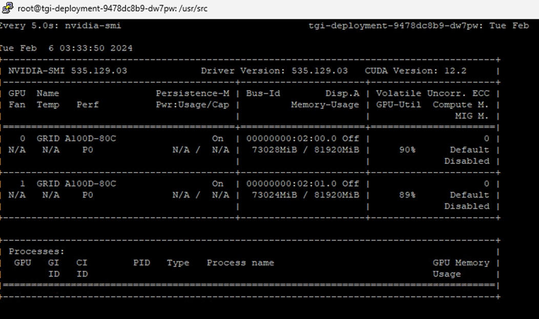
Figure 23 shows the NVIDIA DGCM Exporter Dashboard from the OCP Console showing GPU Framebuffer Usage while running the tests on the models above.
Figure 23. GPU Benchmark Framebuffer Usage during TGI Tests
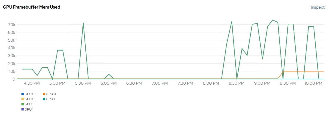
PyTorch is a GPU accelerated tensor computational framework. The PyTorch container from the NVIDIA NGC Catalog is optimized for GPU acceleration and contains a validated set of libraries that enable and optimize GPU performance. Table 10 lists the models run on the modified PyTorch NGC container.
Table 10. Models Run on PyTorch
| Model |
Download Location |
| Llama-2-7B-Chat |
https://llama.meta.com/llama-downloads |
| Llama-2-13B-Chat |
https://llama.meta.com/llama-downloads |
Procedure 1. Deployment
Step 1. To prepare to download the Llama 2 models, visit https://llama.meta.com/llama-downloads and fill out the form. You should receive an email with instructions on downloading the models. Model download will be done later in this deployment.
Step 2. Build the modified PyTorch NGC container using podman with the Dockerfile below and push the resulting image to a container registry.
FROM nvcr.io/nvidia/pytorch:23.10-py3
#Additional packages required to run the application can be installed
RUN apt-get update && apt-get install -y \
apache2 \
curl \
git \
python3-pip
RUN git clone https://github.com/facebookresearch/llama.git
RUN pip install -r /workspace/llama/requirements.txt
Step 3. Create a “llama-2” project in the Openshift console and then create a 100GB PVC. In this example, NVMe-TCP storage is used and requires Single user access.
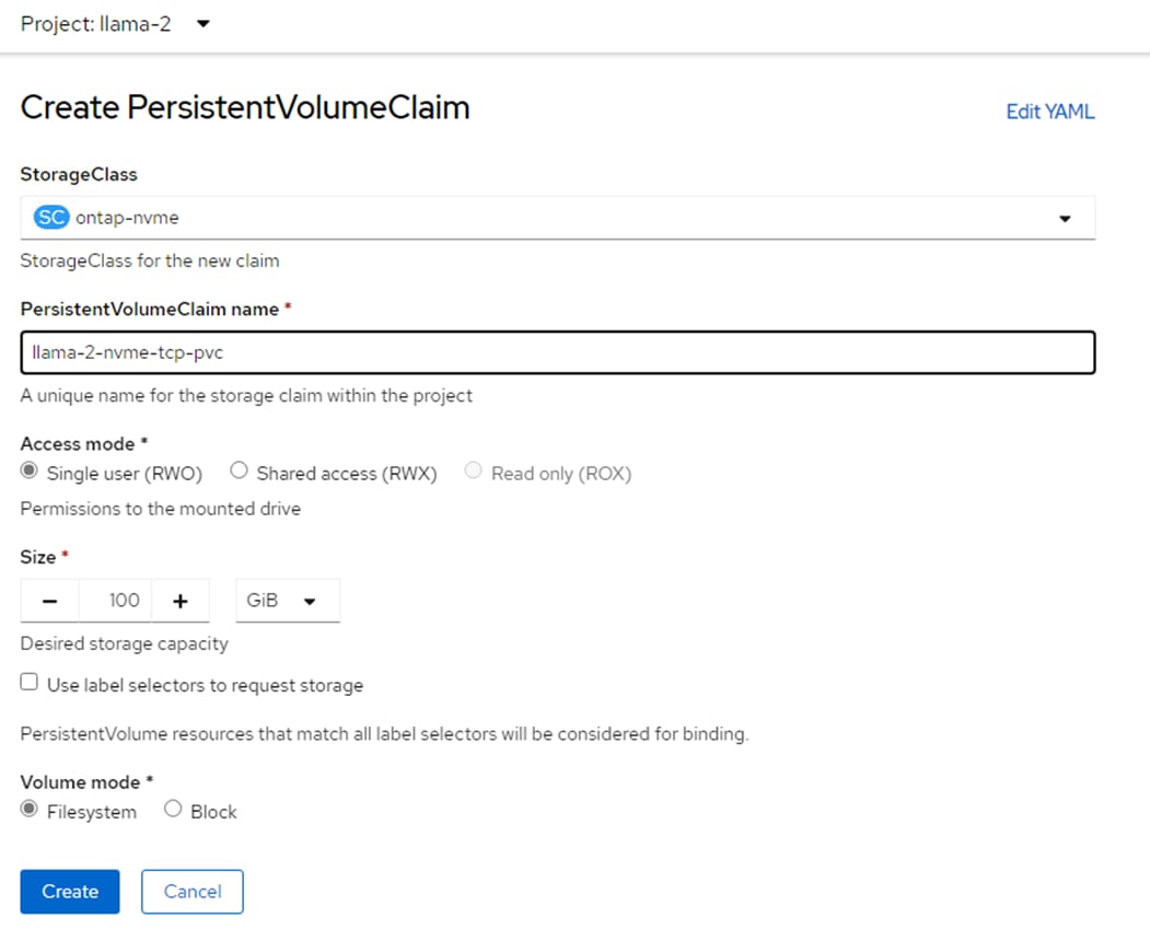
Step 4. Use the following deployment.yaml to deploy the container.
Note: The container will need to be run as root.
apiVersion: apps/v1
kind: Deployment
metadata:
name: llama-2-deployment
spec:
replicas: 1
selector:
matchLabels:
app: llama-2
template:
metadata:
labels:
app: llama-2
name: llama-2-pod
spec:
#NetApp Astra Trident PVC to store the model weights and tokenizer
volumes:
- name: model-repository
persistentVolumeClaim:
claimName: llama-2-nvme-tcp-pvc
containers:
- name: llama-2-container
image: quay.io/<user-id>/llama-2
command: [ "/bin/bash", "-c", "--" ]
args: [ "while true; do sleep 30; done;" ]
resources:
limits:
nvidia.com/gpu: 2 # requesting 2 GPUs
volumeMounts:
- name: model-repository
mountPath: /model_repository
Step 5. Once the container is running, connect to it and download the llama-2-13b-chat and llama-2-7b-chat models.
oc get pods
NAME READY STATUS RESTARTS AGE
llama-2-deployment-8555b5f975-7w6nc 1/1 Running 0 85m
oc exec -it llama-2-deployment-8555b5f975-7w6nc -- bash
cp -r llama/* /model_repository/
cd /model_repository
./download.sh – Enter the URL from the email and specify “7B-chat,13B-chat”
Step 6. To see the NVMe-TCP storage mount for this container, run the following (partial output listing).
df -h
Filesystem Size Used Avail Use% Mounted on
overlay 512G 164G 348G 33% /
tmpfs 64M 0 64M 0% /dev
shm 64M 0 64M 0% /dev/shm
tmpfs 48G 132M 48G 1% /etc/hostname
/dev/nvme0n1 100G 38G 63G 38% /model_repository
/dev/sda4 512G 164G 348G 33% /etc/hosts
Step 7. The NVMe-TCP storage paths can be seen from the worker node. In the OCP console, select Compute > Nodes. Select the worker that is running the Llama 2 container (obtained by running “oc get pods -o wide” in the project for Llama 2) and selecting the Terminal tab. The NVMe-TCP paths can be shown as in the following screenshot:
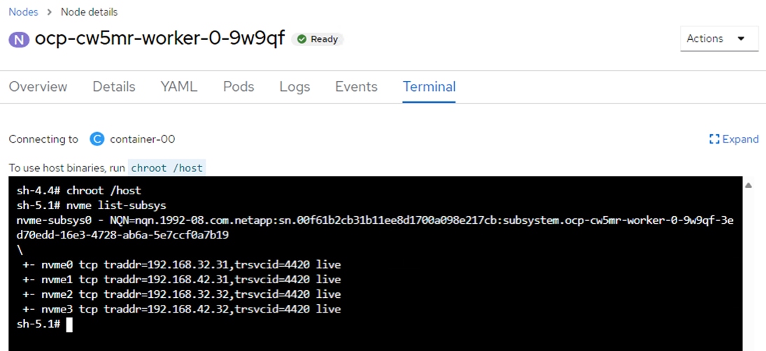
Results
When running the following commands, the Llama-2-7B-Chat model with 1 vGPU loaded in 11.46 seconds and ran in 26.473 seconds. The Llama-2-13B-Chat model with 2 vGPUs loaded in 16.78 seconds and ran in 41.532 seconds.
time torchrun --nproc_per_node 1 example_chat_completion.py --ckpt_dir llama-2-7b-chat/ --tokenizer_path tokenizer.model --max_seq_len 512 --max_batch_size 6
time torchrun --nproc_per_node 2 example_chat_completion.py --ckpt_dir llama-2-13b-chat/ --tokenizer_path tokenizer.model --max_seq_len 512 --max_batch_size 6
NVMe-TCP persistent storage was used with this model where the NVMe namespace is mapped to the OCP worker VM with four paths through two NVMe-TCP interfaces. Openshift then connects the storage to the container. These path connections were tested by disabling different combinations of the NVMe-TCP logical interfaces (LIFs) on the NetApp storage SVM hosting the OCP tenant and running the tests above. Disabling LIFs had very little effect on tests as long as at least one path was available.
Stable Diffusion is an open source image generation model that allows to generate images using a simple text prompt.
Stable Diffusion is a text-to-image latent diffusion model created by the researchers and engineers from CompVis, Stability AI and LAION. It is trained on 512x512 images from a subset of the LAION-5B database. LAION-5B is the largest, freely accessible multi-modal dataset that currently exists.
Some of the image related tasks it performs are:
● Text-to-Image: Create an image from a text prompt.
● Image-to-Image: Create an image from an existing image and a text prompt.
● Depth-Guided Diffusion: Modify an existing image with its depth map and a text prompt.
● Instruct Pix2Pix: Modify an existing image with a text prompt.
● Stable UnCLIP Variations: Create different versions of an image with a text prompt.
● Image Upscaling: Create a high-resolution image from an existing image with a text prompt.
● Diffusion Inpainting: Modify specific areas of an existing image with an image mask and a text prompt.
Table 11. Stable Diffusion versions
| Model |
Models in Hugging Face |
| Stable Diffusion 1.4 |
https://huggingface.co/CompVis/stable-diffusion-v1-4 |
| Stable Diffusion 1.5 |
https://huggingface.co/runwayml/stable-diffusion-v1-5 |
| Stable Diffusion 2 |
https://huggingface.co/stabilityai/stable-diffusion-2 |
| Stable Diffusion 2.1 |
https://huggingface.co/stabilityai/stable-diffusion-2-1 |
| Stable Diffusion XL |
https://huggingface.co/stabilityai/stable-diffusion-xl-base-1.0 |
All tests are performed on Jupyter notebook, which was created using NetApp DataOps toolkit.
netapp_dataops_k8s_cli.py create jupyterlab --workspace-name=ai-models -c ontap-nas-sc --size=90Gi --nvidia-gpu=1 -i nvcr.io/nvidia/pytorch:23.10-py3
We used a persistent volume claim (PVC) which was created using the Astra Trident NFS StorageClass (ontap-nas-sc).
Once the notebook is created, the following code is used to test the model:
pip install --upgrade diffusers transformers scipy
import torch
from diffusers import StableDiffusionPipeline
model_id = "CompVis/stable-diffusion-v1-4"
device = "cuda"
pipe = StableDiffusionPipeline.from_pretrained(model_id, torch_dtype=torch.float16)
pipe = pipe.to(device)
prompt = "A photo of a cat wearing a hat"
image = pipe(prompt).images[0]
image.save("cat_wearing_hat.png")
The following image is generated by Stable Diffusion 1.4 for the prompt:

The inferencing was run with one A100 GPU. 16% of tensor core utilization with 4.3 Gigabyte of memory was consumed:
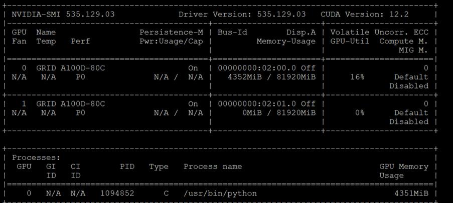
For Stable Diffusion XL 1.0, use the following python script:
import torch
from diffusers import StableDiffusionXLPipeline
model_id = "stabilityai/stable-diffusion-xl-base-1.0"
device = "cuda"
pipe = StableDiffusionXLPipeline.from_pretrained(model_id, torch_dtype=torch.float16)
pipe = pipe.to(device)
prompt = "Astronaut in a jungle, cold color palette, muted colors, detailed, 8k resolution"
image = pipe(prompt).images[0]
image.save("astronaut.png")
The following image is generated by Stable Diffusion XL 1.0-base model for the prompt “Astronaut in a jungle, cold color palette, muted colors, detailed, 8k resolution.”

Stable Diffusion XL can also be run just utilizing the Intel CPUs in the server under OpenVINO with the following:
pip install optimum[openvino]
Then use the following Python script:
from optimum.intel import OVStableDiffusionXLPipeline
model_id = "stabilityai/stable-diffusion-xl-base-1.0"
pipeline = OVStableDiffusionXLPipeline.from_pretrained(model_id)
prompt = "Astronaut in a jungle, cold color palette, muted colors, detailed, 8k resolution"
image = pipeline(prompt).images[0]
image.save("astronaut_intel.png")
Running this image generation using the NVIDIA GPU completed in 20.3 seconds, while running the image generation using only the CPU took 2 minutes 1.8 seconds.
Openjourney is an open-source Stable Diffusion fine-tuned model on Midjourney images. This model can be used just like any other Stable Diffusion model.
Note: Include 'mdjrny-v4 style' in prompt.
Hugging face: https://huggingface.co/prompthero/openjourney
This code is used to test the model:
from diffusers import StableDiffusionPipeline
import torch
model_id = "prompthero/openjourney"
pipe = StableDiffusionPipeline.from_pretrained(model_id, torch_dtype=torch.float16)
pipe = pipe.to("cuda")
prompt = "a lonely astronaut floating in space, surrounded by stars and planets, mdjrny-v4 style"
image = pipe(prompt).images[0]
image.save("./astronaut.png")
The following image is generated for the prompt:

The inferencing was run with one A100 GPU. 50% of tensor core utilization with 4.3 Gigabyte of memory was consumed.
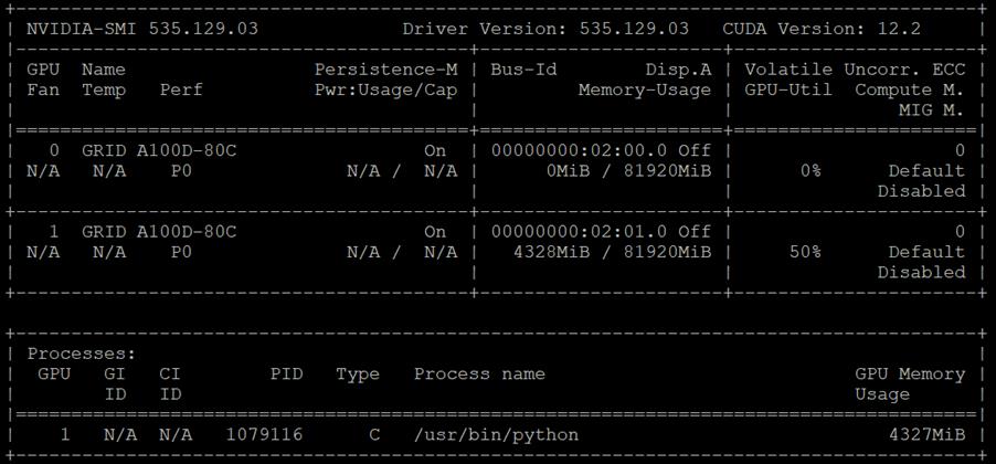
Dreamlike Diffusion 1.0 is SD 1.5 fine tuned on high quality art, made by dreamlike.art. We used the same inferencing method as Stable Diffusion for Dreamlike Diffusion as well.
Note: Use the same prompts as you would for SD 1.5. Add dreamlikeart if the artstyle is too weak.
Hugging face: https://huggingface.co/dreamlike-art/dreamlike-diffusion-1.0
This code is used to test the model:
from diffusers import StableDiffusionPipeline
import torch
model_id = "dreamlike-art/dreamlike-diffusion-1.0"
pipe = StableDiffusionPipeline.from_pretrained(model_id, torch_dtype=torch.float16)
pipe = pipe.to("cuda")
prompt = "dreamlikeart, a dark fantasy castle on a cliff, surrounded by mist and lightning, in the style of Simon Stålenhag, detailed, realistic, gloomy, ominous, sci-fi elements, flying cars, robots, drones, cyberpunk, dystopian, 16:9 aspect ratio"
image = pipe(prompt).images[0]
image.save("./result.jpg")
The following image is generated by the prompt:

The inferencing was run with one A100 GPU. 56% of tensor core utilization with 2.8 Gigabyte of memory was consumed.
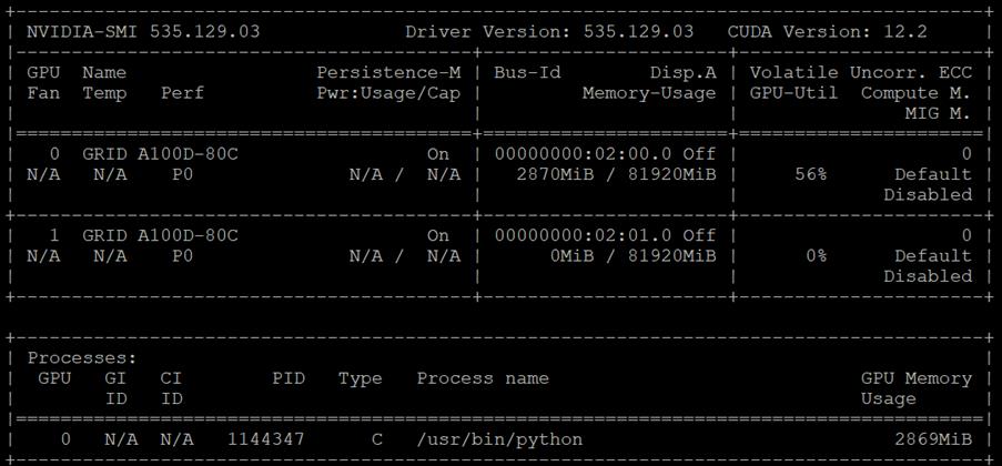
Hotshot-XL is an AI text-to-GIF model trained to work alongside Stable Diffusion XL. Hotshot-XL was trained to generate 1 second GIFs at 8 FPS.
Hotshot-XL can generate GIFs with any fine-tuned SDXL model. It is possible to make GIFs with any existing or newly fine-tuned SDXL model.
A new terminal is created on Jupyter notebook which was created using NetApp DataOps toolkit to test the model.
Git repo: https://github.com/hotshotco/Hotshot-XL
Hugging face: https://huggingface.co/hotshotco/Hotshot-XL
Clone the Git repo then use the following code to test the model:
git clone https://github.com/hotshotco/Hotshot-XL
cd Hotshot-XL
Environment Setup:
pip install virtualenv --upgrade
virtualenv -p $(which python3) venv
source venv/bin/activate
pip install -r requirements.txt
Download the Hotshot-XL Weights:
# Make sure you have git-lfs installed (https://git-lfs.com)
git lfs install
git clone https://huggingface.co/hotshotco/Hotshot-XL
Download our fine-tuned SDXL model (or BYOSDXL):
# Make sure you have git-lfs installed (https://git-lfs.com)
git lfs install
git clone https://huggingface.co/hotshotco/SDXL-512
Text-to-GIF with ControlNet:
python inference.py \
--prompt="a girl jumping up and down and pumping her fist, hd, high quality" \
--output="output.gif" \
--control_type="depth" \
--gif="https://media1.giphy.com/media/v1.Y2lkPTc5MGI3NjExbXNneXJicG1mOHJ2dzQ2Y2JteDY1ZWlrdjNjMjl3ZWxyeWFxY2EzdyZlcD12MV9pbnRlcm5hbF9naWZfYnlfaWQmY3Q9Zw/YOTAoXBgMCmFeQQzuZ/giphy.gif"
If git-lfs is not installed, run the following:
curl -s https://packagecloud.io/install/repositories/github/git-lfs/script.deb.sh | bash
apt-get install git-lfs
A GIF image is generated for the prompt:

The inferencing was run with one A100 GPU. 64% of tensor core utilization with 12 Gigabyte of memory was consumed.
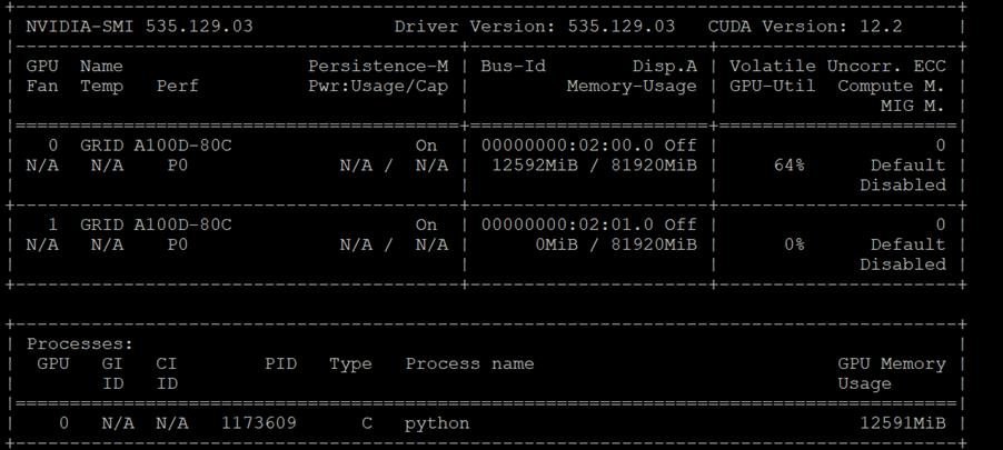
Deep learning has evolved a lot in recent years and we all are excited to build deeper architecture networks to gain more accuracies for our models. These techniques are widely tried for Image related works like classification, clustering, or synthesis.
Resnet models were proposed in “Deep Residual Learning for Image Recognition.” Here we have the 5 versions of Resnet models, which contains 18, 34, 50, 101, 152 layers, respectively. In this document, we will look at one of the healthcare use case (Diabetic Retinopathy Detection) Of ResNet-34 model using the Pytorch framework in Python.
Deployment
Create a Jupyter notebook using NetApp DataOps toolkit to execute the model:
netapp_dataops_k8s_cli.py create jupyterlab --workspace-name=flexpod -c ontap-nas-sc --size=90Gi --nvidia-gpu=1 -i nvcr.io/nvidia/pytorch:23.10-py3
A persistent volume claim (PVC) was used and was created using the Astra Trident NFS StorageClass (ontap-nas-sc).
To download sample training and test dataset, go to: https://www.kaggle.com/code/balajiai/diabetic-retinopathy-detection-using-pytorch/input.
To import libraries, Preprocess the Data, build the model, creating functions for training and validation, optimize and test the model, we have referred: https://www.kaggle.com/code/balajiai/diabetic-retinopathy-detection-using-pytorch/notebook
Results
We optimized the model using 60 Epoch. The following graph shows the training and validation loss.
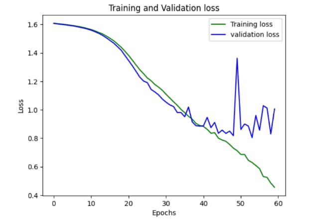
We achieved 88 percent accuracy on training set and around 78% accuracy on validation set.
The inferencing was run with one A100 GPU. 3% of tensor core utilization with 9.3 Gigabyte of memory was consumed in each epoch.
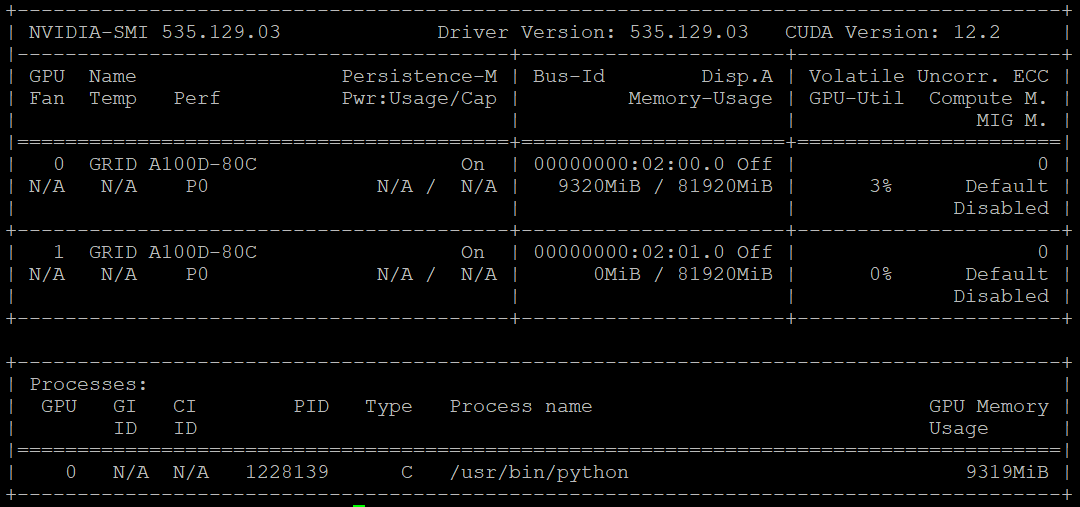
Note: You can increase the accuracy of the model by various ways, like increasing the dataset size, increasing the model complexity, and increasing the number of epochs.
Note: We executed the model using CPU and NVIDIA A100 GPU. Optimization of model works 2.5x times faster with GPU.
John George, Technical Marketing Engineer, Cisco Systems, Inc.
John is involved in designing, developing, validating, and supporting the FlexPod Converged Infrastructure since its inception. Prior to his role with FlexPod, John supported and administered a large worldwide training network and VPN infrastructure. John holds a master’s degree in Computer Engineering from Clemson University.
Ruchika Lahoti—Technical Marketing Engineer, NetApp
Ruchika has more than six years of experience in the IT industry. She focuses on FlexPod hybrid cloud infrastructure solution design, implementation, validation, automation. Ruchika earned a bachelor’s degree in computer science.
Acknowledgements
For their support and contribution to the design, validation, and creation of this Cisco Validated Design, the authors would like to thank:
● Paniraja Koppa, Technical Marketing Engineer, Cisco Systems, Inc.
● Archana Sharma, Technical Marketing Engineer, Cisco Systems, Inc.
● Haseeb Niazi, Principal Technical Marketing Engineer, Cisco Systems, Inc.
For comments and suggestions about this guide and related guides, join the discussion on Cisco Community at https://cs.co/en-cvds.
CVD Program
ALL DESIGNS, SPECIFICATIONS, STATEMENTS, INFORMATION, AND RECOMMENDATIONS (COLLECTIVELY, "DESIGNS") IN THIS MANUAL ARE PRESENTED "AS IS," WITH ALL FAULTS. CISCO AND ITS SUPPLIERS DISCLAIM ALL WARRANTIES, INCLUDING, WITHOUT LIMITATION, THE WARRANTY OF MERCHANTABILITY, FITNESS FOR A PARTICULAR PURPOSE AND NONINFRINGEMENT OR ARISING FROM A COURSE OF DEALING, USAGE, OR TRADE PRACTICE. IN NO EVENT SHALL CISCO OR ITS SUPPLIERS BE LIABLE FOR ANY INDIRECT, SPECIAL, CONSEQUENTIAL, OR INCIDENTAL DAMAGES, INCLUDING, WITHOUT LIMITATION, LOST PROFITS OR LOSS OR DAMAGE TO DATA ARISING OUT OF THE USE OR INABILITY TO USE THE DESIGNS, EVEN IF CISCO OR ITS SUPPLIERS HAVE BEEN ADVISED OF THE POSSIBILITY OF SUCH DAMAGES.
THE DESIGNS ARE SUBJECT TO CHANGE WITHOUT NOTICE. USERS ARE SOLELY RESPONSIBLE FOR THEIR APPLICATION OF THE DESIGNS. THE DESIGNS DO NOT CONSTITUTE THE TECHNICAL OR OTHER PROFESSIONAL ADVICE OF CISCO, ITS SUPPLIERS OR PARTNERS. USERS SHOULD CONSULT THEIR OWN TECHNICAL ADVISORS BEFORE IMPLEMENTING THE DESIGNS. RESULTS MAY VARY DEPENDING ON FACTORS NOT TESTED BY CISCO.
CCDE, CCENT, Cisco Eos, Cisco Lumin, Cisco Nexus, Cisco StadiumVision, Cisco TelePresence, Cisco WebEx, the Cisco logo, DCE, and Welcome to the Human Network are trademarks; Changing the Way We Work, Live, Play, and Learn and Cisco Store are service marks; and Access Registrar, Aironet, AsyncOS, Bringing the Meeting To You, Catalyst, CCDA, CCDP, CCIE, CCIP, CCNA, CCNP, CCSP, CCVP, Cisco, the Cisco Certified Internetwork Expert logo, Cisco IOS, Cisco Press, Cisco Systems, Cisco Systems Capital, the Cisco Systems logo, Cisco Unified Computing System (Cisco UCS), Cisco UCS B-Series Blade Servers, Cisco UCS C-Series Rack Servers, Cisco UCS S-Series Storage Servers, Cisco UCS Manager, Cisco UCS X-Series, Cisco UCS Management Software, Cisco Unified Fabric, Cisco Application Centric Infrastructure, Cisco Nexus 9000 Series, Cisco Nexus 7000 Series. Cisco Prime Data Center Network Manager, Cisco NX-OS Software, Cisco MDS Series, Cisco Unity, Collaboration Without Limitation, EtherFast, EtherSwitch, Event Center, Fast Step, Follow Me Browsing, FormShare, GigaDrive, HomeLink, Internet Quotient, IOS, iPhone, iQuick Study, LightStream, Linksys, MediaTone, MeetingPlace, MeetingPlace Chime Sound, MGX, Networkers, Networking Academy, Network Registrar, PCNow, PIX, PowerPanels, ProConnect, ScriptShare, SenderBase, SMARTnet, Spectrum Expert, SE1tackWise, The Fastest Way to Increase Your Internet Quotient, TransPath, WebEx, and the WebEx logo are registered trade-marks of Cisco Systems, Inc. and/or its affiliates in the United States and certain other countries. (LDW_P13)
All other trademarks mentioned in this document or website are the property of their respective owners. The use of the word partner does not imply a partnership relationship between Cisco and any other company. (0809R)