FlashStack Virtual Server Infrastructure with iSCSI Storage for VMware vSphere 7.0 iSCSI Channel
Available Languages
Bias-Free Language
The documentation set for this product strives to use bias-free language. For the purposes of this documentation set, bias-free is defined as language that does not imply discrimination based on age, disability, gender, racial identity, ethnic identity, sexual orientation, socioeconomic status, and intersectionality. Exceptions may be present in the documentation due to language that is hardcoded in the user interfaces of the product software, language used based on RFP documentation, or language that is used by a referenced third-party product. Learn more about how Cisco is using Inclusive Language.
- US/Canada 800-553-2447
- Worldwide Support Phone Numbers
- All Tools
 Feedback
 Feedback

FlashStack Virtual Server Infrastructure with iSCSI Storage for VMware vSphere 7.0 iSCSI Channel
Deployment Guide for FlashStack with Cisco UCS 6400 Fabric Interconnects, Cisco UCS M5 Servers, and Pure Storage FlashArray//X R3 Series
Published: December 2020

In partnership with:
![]()
About the Cisco Validated Design Program
The Cisco Validated Design (CVD) program consists of systems and solutions designed, tested, and documented to facilitate faster, more reliable, and more predictable customer deployments. For more information, go to:
http://www.cisco.com/go/designzone.
ALL DESIGNS, SPECIFICATIONS, STATEMENTS, INFORMATION, AND RECOMMENDATIONS (COLLECTIVELY, "DESIGNS") IN THIS MANUAL ARE PRESENTED "AS IS," WITH ALL FAULTS. CISCO AND ITS SUPPLIERS DISCLAIM ALL WARRANTIES, INCLUDING, WITHOUT LIMITATION, THE WARRANTY OF MERCHANTABILITY, FITNESS FOR A PARTICULAR PURPOSE AND NONINFRINGEMENT OR ARISING FROM A COURSE OF DEALING, USAGE, OR TRADE PRACTICE. IN NO EVENT SHALL CISCO OR ITS SUPPLIERS BE LIABLE FOR ANY INDIRECT, SPECIAL, CONSEQUENTIAL, OR INCIDENTAL DAMAGES, INCLUDING, WITHOUT LIMITATION, LOST PROFITS OR LOSS OR DAMAGE TO DATA ARISING OUT OF THE USE OR INABILITY TO USE THE DESIGNS, EVEN IF CISCO OR ITS SUPPLIERS HAVE BEEN ADVISED OF THE POSSIBILITY OF SUCH DAMAGES.
THE DESIGNS ARE SUBJECT TO CHANGE WITHOUT NOTICE. USERS ARE SOLELY RESPONSIBLE FOR THEIR APPLICATION OF THE DESIGNS. THE DESIGNS DO NOT CONSTITUTE THE TECHNICAL OR OTHER PROFESSIONAL ADVICE OF CISCO, ITS SUPPLIERS OR PARTNERS. USERS SHOULD CONSULT THEIR OWN TECHNICAL ADVISORS BEFORE IMPLEMENTING THE DESIGNS. RESULTS MAY VARY DEPENDING ON FACTORS NOT TESTED BY CISCO.
CCDE, CCENT, Cisco Eos, Cisco Lumin, Cisco Nexus, Cisco StadiumVision, Cisco TelePresence, Cisco WebEx, the Cisco logo, DCE, and Welcome to the Human Network are trademarks; Changing the Way We Work, Live, Play, and Learn and Cisco Store are service marks; and Access Registrar, Aironet, AsyncOS, Bringing the Meeting To You, Catalyst, CCDA, CCDP, CCIE, CCIP, CCNA, CCNP, CCSP, CCVP, Cisco, the Cisco Certified Internetwork Expert logo, Cisco IOS, Cisco Press, Cisco Systems, Cisco Systems Capital, the Cisco Systems logo, Cisco Unified Computing System (Cisco UCS), Cisco UCS B-Series Blade Servers, Cisco UCS C-Series Rack Servers, Cisco UCS S-Series Storage Servers, Cisco UCS Manager, Cisco UCS Management Software, Cisco Unified Fabric, Cisco Application Centric Infrastructure, Cisco Nexus 9000 Series, Cisco Nexus 7000 Series. Cisco Prime Data Center Network Manager, Cisco NX-OS Software, Cisco MDS Series, Cisco Unity, Collaboration Without Limitation, EtherFast, EtherSwitch, Event Center, Fast Step, Follow Me Browsing, FormShare, GigaDrive, HomeLink, Internet Quotient, IOS, iPhone, iQuick Study, LightStream, Linksys, MediaTone, MeetingPlace, MeetingPlace Chime Sound, MGX, Networkers, Networking Academy, Network Registrar, PCNow, PIX, PowerPanels, ProConnect, ScriptShare, SenderBase, SMARTnet, Spectrum Expert, StackWise, The Fastest Way to Increase Your Internet Quotient, TransPath, WebEx, and the WebEx logo are registered trademarks of Cisco Systems, Inc. and/or its affiliates in the United States and certain other countries. LDR1.
All other trademarks mentioned in this document or website are the property of their respective owners. The use of the word partner does not imply a partnership relationship between Cisco and any other company. (0809R)
© 2020 Cisco Systems, Inc. All rights reserved.
Contents
Deployment Hardware and Software
Cisco Validate Designs consist of systems and solutions that are designed, tested, and documented to facilitate and improve customer deployments. These designs incorporate a wide range of technologies and products into a portfolio of solutions that have been developed to address the business needs of our customers.
This document details the design in the FlashStack Virtual Server Infrastructure Design Guide for VMware vSphere 7.0, which describes a validated converged infrastructure jointly developed by Cisco and Pure Storage. This solution covers the deployment of a predesigned, best-practice data center architecture with VMware vSphere built on the Cisco Unified Computing System (Cisco UCS), the Cisco Nexus® 9000 family of switches, and Pure Storage FlashArray//X all flash storage configured for iSCSI-based storage access.
When deployed, the architecture presents a robust infrastructure viable for a wide range of application workloads implemented as a virtual server infrastructure
In the current industry there is a trend for pre-engineered solutions which standardize the data center infrastructure, offering the business operational efficiencies, agility, and scale to address cloud, bimodal IT, and their business. Their challenge is complexity, diverse application support, efficiency, and risk; all these are met by FlashStack with:
● Reduced complexity and automatable infrastructure and easily deployed resources
● Robust components capable of supporting high performance and high bandwidth virtualized applications
● Efficiency through optimization of network bandwidth and in-line storage compression with de-duplication
● Risk reduction at each level of the design with resiliency built into each touch point throughout
Cisco and Pure Storage have partnered to deliver this Cisco Validated Design, which uses best of breed storage, server, and network components to serve for the foundation for virtualized workloads, enabling efficient architectural designs that can be quickly and confidently deployed.
This document describes a reference architecture detailing a Virtual Server Infrastructure composed of Cisco Nexus switches, Cisco UCS Compute, Cisco MDS Multilayer Fabric Switches, and a Pure Storage FlashArray//X delivering a VMware vSphere 7.0 hypervisor environment.
The audience for this document includes, but is not limited to; sales engineers, field consultants, professional services, IT managers, partner engineers, and customers who want to take advantage of an infrastructure built to deliver IT efficiency and enable IT innovation.
This document details a step-by-step configuration and implementation guide for FlashStack, centered around the Cisco UCS 6454 Fabric Interconnect and the Pure Storage FlashArray//X50 R3. These components are supported by the 1/10/25/40/50/100G capable Cisco Nexus 93180YC-FX switch to deliver a Virtual Server infrastructure on Cisco UCS C125 M5 Server nodes and Cisco UCS B200 M5 Blade Servers running VMware vSphere 7.0.
The design that will be implemented is discussed in the FlashStack Virtual Server Infrastructure for VMware vSphere 7.0 Design Guide.
Figure 1. FlashStack with Cisco UCS 6454 and Pure Storage FlashArray //50 R3
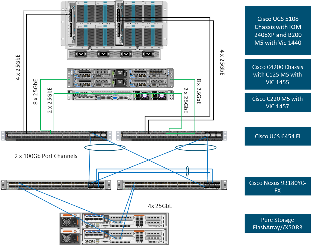
The reference hardware configuration includes:
● Two Cisco Nexus 93180YC-FX Switches
● Two Cisco UCS 6454 Fabric Interconnects
● Cisco UCS 5108 Chassis with two Cisco UCS 2408 Fabric Extenders
● Four Cisco UCS B200 M5 Blade Servers
● Four Cisco UCS C125 M5 Server Nodes
● One Pure Storage FlashArray//X50 R3
The virtual environment this supports is within VMware vSphere 7.0 and includes virtual management and automation components from Cisco and Pure Storage built into the solution, or as optional add-ons.
This document will provide a low-level example of steps to deploy this base architecture that may need some adjustments depending on the customer environment. These steps include physical cabling, network, storage, compute, and virtual device configurations
This FlashStack Datacenter with VMware vSphere 7.0 validated design introduced new hardware and software into the portfolio, enabling 10/25/40/100GbE via the Cisco Nexus 93180YC-FX switch. This primary design has been updated to include the latest Cisco and NetApp hardware and software. New pieces include:
● Support for the Cisco UCS 4.1(2) unified software release, Cisco UCS C125 servers with AMD EPYC 2nd Generation Processors, Cisco UCS B200-M5 and C220-M5 servers with 2nd Generation Intel Xeon Scalable Processors, and Cisco 1400 Series Virtual Interface Cards (VICs)
● Support for the latest Cisco UCS 6454 and 64108 (supported but not validated) Fabric Interconnects
● Support for the latest Cisco UCS 2408 Fabric Extender
● Support for Cisco Intersight Software as a Service (SaaS) Management
● Support for the Pure Storage FlashArray//X R3 array
● Support for the latest release of Pure Storage Purity 6
● Validation of VMware vSphere 7.0
● Unified Extensible Firmware Interface (UEFI) Secure Boot of VMware ESXi 7.0
● 25 or 100 Gigabit per second Ethernet Connectivity
Deployment Hardware and Software
Table 1 lists the software versions for hardware and virtual components used in this solution. Each of these versions have been used have been certified within interoperability matrixes supported by Cisco, Pure Storage, and VMware. For more current supported version information, consult the following sources:
● Cisco UCS Hardware and Software Interoperability Tool: http://www.cisco.com/web/techdoc/ucs/interoperability/matrix/matrix.html
● Pure Storage Interoperability(note, this interoperability list will require a support login form Pure): https://support.purestorage.com/FlashArray/Getting_Started/Compatibility_Matrix
● Pure Storage FlashStack Compatibility Matrix (note, this interoperability list will require a support login from Pure): https://support.purestorage.com/FlashStack/Product_Information/FlashStack_Compatibility_Matrix
● VMware Compatibility Guide: http://www.vmware.com/resources/compatibility/search.php
● Additionally, it is also strongly suggested to align FlashStack deployments with the recommended release for the Cisco Nexus 9000 switches used in the architecture:
If versions are selected that differ from the validated versions below, it is highly recommended to read the release notes of the selected version to be aware of any changes to features or commands that may have occurred.
| Layer |
Device |
Image |
Comments |
| Compute |
Cisco UCS Fabric Interconnects 6400 Series, UCS B-200 M5, UCS C-220 M5 |
4.1(2a) |
Includes Cisco UCS IOM 2408 and Cisco VIC 1400 Series |
| Network |
Cisco Nexus 9000 NX-OS |
9.3(5) |
|
| Storage |
Pure Storage FlashArray//X50 R3 |
6.0.2 |
|
| Software |
Cisco UCS Manager |
4.1(2a) |
|
|
|
VMware vSphere ESXi Cisco Custom ISO |
7.0 |
|
|
|
nenic Driver for ESXi |
1.0.33.0 |
|
|
|
nfnic Driver for ESXi |
4.0.0.56 |
|
|
|
VMware vCenter |
7.0 |
|
This document details the step-by-step configuration of a fully redundant and highly available Virtual Server Infrastructure built on Cisco and Pure Storage components. References are made to which component is being configured with each step, either 01 or 02 or A and B. For example, controller-1 and controller-2 are used to identify the two controllers within the Pure Storage FlashArray//X that are provisioned with this document, and Cisco Nexus A or Cisco Nexus B identifies the pair of Cisco Nexus switches that are configured. The Cisco UCS fabric interconnects are similarly configured. Additionally, this document details the steps for provisioning multiple Cisco UCS hosts, and these examples are identified as: VM-Host-iSCSI-01, VM-Host-iSCSI-02 to represent iSCSI booted infrastructure and production hosts deployed to the fabric interconnects in this document. Finally, to indicate that you should include information pertinent to your environment in each step, <<text>> appears as part of the command structure. See the following example during a configuration step for both Nexus switches:
BB08-93180YC-FX-A (config)# ntp server <<var_oob_ntp>> use-vrf management
This document is intended to enable you to fully configure the customer environment. In this process, various steps require you to insert customer-specific naming conventions, IP addresses, and VLAN schemes, as well as to record appropriate MAC addresses. Table 2 lists the VLANs necessary for deployment as outlined in this guide, and Table 3 lists the external dependencies necessary for deployment as outlined in this guide.
| VLAN Name |
VLAN Purpose |
ID Used in Validating this Document |
Customer Deployed Value |
| Native |
VLAN for untagged frames |
2 |
|
| Out-of-Band Mgmt |
VLAN for out-of-band management interfaces |
15 |
|
| In-band Mgmt |
VLAN for in-band management interfaces |
215 |
|
| vMotion |
VLAN for vMotion |
1130 |
|
| iSCSI-A |
A-side iSCSI vlan |
901 |
|
| iSCSI-B |
B-side iSCSI vlan |
902 |
|
| VM-App-1301 |
VLAN for Production VM interfaces |
1301 |
|
| VM-App-1302 |
VLAN for Production VM interfaces |
1302 |
|
| VM-App-1303 |
VLAN for Production VM interfaces |
1303 |
|
Table 3. Infrastructure Servers
| Server Description |
Server Name Used in Validating This Document |
Customer Deployed Value |
| vCenter Server |
Pure-VC |
|
| Active Directory |
Pure-AD |
|
Table 4. Configuration Variables
| Variable Name |
Variable Description |
Customer Deployed Value |
| <<var_nexus_A_hostname>> |
Cisco Nexus switch A Host name (Example: AA12-9336C-A) |
|
| <<var_nexus_A_mgmt_ip>> |
Out-of-band management IP for Cisco Nexus switch A (Example: 192.168.164.90) |
|
| <<var_oob_mgmt_mask>> |
Out-of-band network mask (Example: 255.255.255.0) |
|
| <<var_oob_gateway>> |
Out-of-band network gateway (Example: 192.168.164.254) |
|
| <<var_oob_ntp>> |
Out-of-band management network NTP Server (Example: 172.26.163.254) |
|
| <<var_nexus_B_hostname>> |
Cisco Nexus switch B Host name (Example: AA12-9336C-B) |
|
| <<var_nexus_B_mgmt_ip>> |
Out-of-band management IP for Cisco Nexus switch B (Example: 162.168.164.91) |
|
| <<var_flasharray_hostname>> |
Array Hostname set during setup (Example: flashstack-1) |
|
| <<var_flasharray_vip>> |
Virtual IP that will answer for the active management controller (Example: 10.2.164.45) |
|
| <<var_contoller-1_mgmt_ip>> |
Out-of-band management IP for FlashArray controller-1 (Example:10.2.164.47) |
|
| <<var_contoller-1_mgmt_mask>> |
Out-of-band management network netmask (Example: 255.255.255.0) |
|
| <<var_contoller-1_mgmt_gateway>> |
Out-of-band management network default gateway (Example: 192.168.164.254) |
|
| <<var_contoller-2_mgmt_ip>> |
Out-of-band management IP for FlashArray controller-2 (Example:10.2.164.49) |
|
| <<var_contoller-2_mgmt_mask>> |
Out-of-band management network netmask (Example: 255.255.255.0) |
|
| <<var_ contoller-2_mgmt_gateway>> |
Out-of-band management network default gateway (Example: 192.168.164.254) |
|
| <<var_password>> |
Administrative password (Example: Fl@shSt4x) |
|
| <<var_dns_domain_name>> |
DNS domain name (Example: flashstack.cisco.com) |
|
| <<var_nameserver_ip>> |
DNS server IP(s) (Example: 10.1.164.9) |
|
| <<var_smtp_ip>> |
Email Relay Server IP Address or FQDN (Example: smtp.flashstack.cisco.com) |
|
| <<var_smtp_domain_name>> |
Email Domain Name (Example: flashstack.cisco.com) |
|
| <<var_timezone>> |
FlashStack time zone (Example: America/New_York) |
|
| <<var_oob_mgmt_vlan_id>> |
Out-of-band management network VLAN ID (Example: 15) |
|
| <<var_ib_mgmt_vlan_id>> |
In-band management network VLAN ID (Example: 215) |
|
| <<var_ib_mgmt_vlan_netmask_length>> |
Length of IB-MGMT-VLAN Netmask (Example: /24) |
|
| <<var_ib_gateway_ip>> |
In-band management network VLAN ID (Example: 10.2.164.254) |
|
| <<var_vmotion_vlan_id>> |
vMotion network VLAN ID (Example: 1130) |
|
| <<var_vmotion_vlan_netmask_length>> |
Length of vMotion VLAN Netmask (Example: /24) |
|
| <<var_native_vlan_id>> |
Native network VLAN ID (Example: 2) |
|
| <<var_app_vlan_id>> |
Example Application network VLAN ID (Example: 1301) |
|
| <<var_snmp_contact>> |
Administrator e-mail address (Example: admin@flashstack.cisco.com) |
|
| <<var_snmp_location>> |
Cluster location string (Example: RTP9-AA12) |
|
| <<var_vlan_iscsi-a_id>> |
VLAN used for the A Fabric between the FlashArray/Nexus/FI (Example: 901) |
|
| <<var_vlan_iscsi-b_id>> |
VLAN used for the B Fabric between the FlashArray/Nexus/FI (Example: 902) |
|
| <<var_ucs_clustername>> |
Cisco UCS Manager cluster host name (Example: AA-12-ucs-6454) |
|
| <<var_ucs_a_mgmt_ip>> |
Cisco UCS Fabric Interconnect (FI) A out-of-band management IP address (Example: 10.2.164.51) |
|
| <<var_ucs_mgmt_vip>> |
Cisco UCS Fabric Interconnect (FI) Cluster out-of-band management IP address (Example: 10.2.164.50) |
|
| <<var_ucs b_mgmt_ip>> |
Cisco UCS Fabric Interconnect (FI) Cluster out-of-band management IP address (Example: 10.2.164.52) |
|
| <<var_vm_host_iscsi_01_ip>> |
VMware ESXi host 01 in-band management IP (Example:10.2.164.73) |
|
| <<var_vm_host_iscsi_vmotion_01_ip>> |
VMware ESXi host 01 vMotion IP (Example: 192.168.130.73) |
|
| <<var_vm_host_iscsi_02_ip>> |
VMware ESXi host 02 in-band management IP (Example:10.2.164.74) |
|
| <<var_vm_host_iscsi_vmotion_02_ip>> |
VMware ESXi host 02 vMotion IP (Example: 192.168.130.74) |
|
| <<var_vmotion_subnet_mask>> |
vMotion subnet mask (Example: 255.255.255.0) |
|
| <<var_vcenter_server_ip>> |
IP address of the vCenter Server (Example: 10.1.164.20) |
|
This section details a cabling example for a FlashStack environment. To make connectivity clear in this example, the tables include both the local and remote port locations.
This document assumes that out-of-band management ports are plugged into an existing management infrastructure at the deployment site. The upstream network from the Cisco Nexus 93180YC-FX switches is out of scope of this document, with only the assumption that these switches will connect to the upstream switch or switches with a vPC.
Figure 2. FlashStack Cabling in Validated Topology
![]() Figure 2 shows fewer connections to the servers in the diagram than are used in the connection table for readability purposes. The connections between the Fabric Interconnects and the Servers are as follows:
Figure 2 shows fewer connections to the servers in the diagram than are used in the connection table for readability purposes. The connections between the Fabric Interconnects and the Servers are as follows:
4 connections from the IOM to the respective Fabric Interconnect
8 connections from the C42000 (1 per server) to each Fabric Interconnect
2 connections from the C220 to each Fabric Interconnect
Table 5. Cisco Nexus 93180YC-FX-A Cabling Information
| Local Device |
Local Port |
Connection |
Remote Device |
Remote port |
| Cisco Nexus 93180YC-FX-A |
Eth 1/37 |
25Gbe |
FlashArray//X50 R3 Controller 1 |
CT0.ETH4 |
| Eth 1/38 |
25Gbe |
FlashArray//X50 R3 Controller 2 |
CT1.ETH4 |
|
| Eth 1/49 |
100Gbe |
Cisco UCS 6454-A |
Eth 1/49 |
|
| Eth 1/50 |
100Gbe |
Cisco UCS 6454-B |
Eth 1/49 |
|
| Eth 1/51 |
100Gbe |
Cisco Nexus 93180YC-FX-B |
Eth 1/51 |
|
| Eth 1/52 |
100Gbe |
Cisco Nexus 93180YC-FX-B |
Eth 1/52 |
|
| Eth 1/53 |
40Gbe or 100Gbe |
Upstream Network Switch |
Any |
|
| Eth 1/54 |
40Gbe or 100Gbe |
Upstream Network Switch |
Any |
|
| Mgmt0 |
Gbe |
Gbe Management Switch |
Any |
Table 6. Cisco Nexus 93180YC-FX-B Cabling Information
| Local Device |
Local Port |
Connection |
Remote Device |
Remote port |
| Cisco Nexus 93180YC-FX-B |
Eth 1/37 |
25Gbe |
FlashArray//X50 R3 Controller 1 |
CT0.ETH5 |
| Eth 1/38 |
25Gbe |
FlashArray//X50 R3 Controller 2 |
CT1.ETH5 |
|
| Eth 1/49 |
100Gbe |
Cisco UCS 6454-A |
Eth 1/50 |
|
| Eth 1/50 |
100Gbe |
Cisco UCS 6454-B |
Eth 1/50 |
|
| Eth 1/51 |
100Gbe |
Cisco Nexus 93180YC-FX-A |
Eth 1/51 |
|
| Eth 1/52 |
100Gbe |
Cisco Nexus 93180YC-FX-A |
Eth 1/52 |
|
| Eth 1/53 |
40Gbe or 100Gbe |
Upstream Network Switch |
Any |
|
| Eth 1/54 |
40Gbe or 100Gbe |
Upstream Network Switch |
Any |
|
| Mgmt0 |
Gbe |
Gbe Management Switch |
Any |
Table 7. Cisco UCS-6545-A Cabling Information
| Local Device |
Local Port |
Connection |
Remote Device |
Remote port |
| Cisco UCS-6454-A |
Eth 1/49 |
100Gbe |
Cisco Nexus 93180YC-FX-A |
Eth 1/49 |
| Eth 1/50 |
100Gbe |
Cisco Nexus 93180YC-FX-B |
Eth 1/50 |
|
| Eth 1/9 |
25Gbe |
Cisco UCS Chassis 1 2408 FEX A |
IOM 1/1 |
|
| Eth 1/10 |
25Gbe |
Cisco UCS Chassis 1 2408 FEX A |
IOM 1/2 |
|
| Eth 1/11 |
25Gbe |
Cisco UCS Chassis 1 2408 FEX A |
IOM 1/3 |
|
| Eth 1/12 |
25Gbe |
Cisco UCS Chassis 1 2408 FEX A |
IOM 1/4 |
|
| Eth 1/17 |
25Gbe |
Cisco UCS C4200 Chassis Server 1 |
DCE 1 |
|
| Eth 1/18 |
25Gbe |
Cisco UCS C4200 Chassis Server 1 |
DCE 2 |
|
| Eth 1/19 |
25Gbe |
Cisco UCS C4200 Chassis Server 2 |
DCE 1 |
|
| Eth 1/20 |
25Gbe |
Cisco UCS C4200 Chassis Server 2 |
DCE 2 |
|
| Eth 1/21 |
25Gbe |
Cisco UCS C4200 Chassis Server 3 |
DCE 1 |
|
| Eth 1/22 |
25Gbe |
Cisco UCS C4200 Chassis Server 3 |
DCE 2 |
|
| Eth 1/23 |
25Gbe |
Cisco UCS C4200 Chassis Server 4 |
DCE 1 |
|
| Eth 1/24 |
25Gbe |
Cisco UCS C4200 Chassis Server 4 |
DCE 2 |
|
| Mgmt0 |
Gbe |
Gbe Management Switch |
Any |
Table 8. Cisco UCS-6545-B Cabling Information
| Local Device |
Local Port |
Connection |
Remote Device |
Remote port |
| Cisco UCS-6454-B |
Eth 1/49 |
100Gbe |
Cisco Nexus 93180YC-FX-A |
Eth 1/49 |
| Eth 1/50 |
100Gbe |
Cisco Nexus 93180YC-FX-B |
Eth 1/50 |
|
| Eth 1/9 |
25Gbe |
Cisco UCS Chassis 1 2408 FEX B |
IOM 1/1 |
|
| Eth 1/10 |
25Gbe |
Cisco UCS Chassis 1 2408 FEX B |
IOM 1/2 |
|
| Eth 1/11 |
25Gbe |
Cisco UCS Chassis 1 2408 FEX B |
IOM 1/3 |
|
| Eth 1/12 |
25Gbe |
Cisco UCS Chassis 1 2408 FEX B |
IOM 1/4 |
|
| Eth 1/17 |
25Gbe |
Cisco UCS C4200 Chassis Server 1 |
DCE 3 |
|
| Eth 1/18 |
25Gbe |
Cisco UCS C4200 Chassis Server 1 |
DCE 4 |
|
| Eth 1/19 |
25Gbe |
Cisco UCS C4200 Chassis Server 2 |
DCE 3 |
|
| Eth 1/20 |
25Gbe |
Cisco UCS C4200 Chassis Server 2 |
DCE 4 |
|
| Eth 1/21 |
25Gbe |
Cisco UCS C4200 Chassis Server 3 |
DCE 3 |
|
| Eth 1/22 |
25Gbe |
Cisco UCS C4200 Chassis Server 3 |
DCE 4 |
|
| Eth 1/23 |
25Gbe |
Cisco UCS C4200 Chassis Server 4 |
DCE 3 |
|
| Eth 1/24 |
25Gbe |
Cisco UCS C4200 Chassis Server 4 |
DCE 4 |
|
| Mgmt0 |
Gbe |
Gbe Management Switch |
Any |
Table 9. Pure Storage FlashArray//X50 R3 Controller 1 Cabling Information
| Local Device |
Local Port |
Connection |
Remote Device |
Remote port |
| FlashArray//X50 R3 Controller 1 |
CT0.ETH4 |
25Gbe |
Cisco Nexus 93180YC-FX-A |
Eth 1/37 |
| CT0.ETH5 |
25Gbe |
Cisco Nexus 93180YC-FX-B |
Eth 1/37 |
|
| Eth0 |
Gbe |
Gbe Management Switch |
Any |
Table 10. Pure Storage FlashArray//X50 R3 Controller 2 Cabling Information
| Local Device |
Local Port |
Connection |
Remote Device |
Remote port |
| FlashArray//X50 R3 Controller 2 |
CT1.ETH4 |
25Gbe |
Cisco Nexus 93180YC-FX-A |
Eth 1/38 |
| CT1.ETH5 |
25Gbe |
Cisco Nexus 93180YC-FX-B |
Eth 1/38 |
|
| Eth0 |
Gbe |
Gbe Management Switch |
Any |
The following procedures describe how to configure the Cisco Nexus switches for use in a base FlashStack environment. This procedure assumes the use of Cisco Nexus 93180YC-FX switches running NX-OS 9.3(5). Configuration on a differing model of Cisco Nexus 9000 series switch should be comparable but may differ slightly with model and changes in NX-OS release. The Cisco Nexus 93180YC-FX switch and NX-OS 9.3(5) release were used in validation of this FlashStack solution, so steps will reflect this model and release.
Figure 3. Network Configuration Workflow
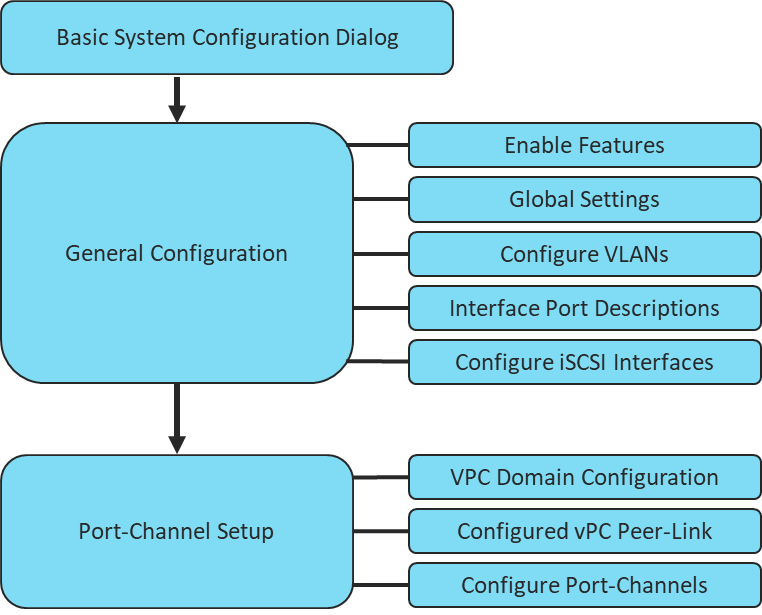
Physical cabling should be completed by following the diagram and table references in the previous section referenced as FlashStack Cabling.
Cisco Nexus Basic System Configuration Dialog
This section provides detailed instructions for the configuration of the Cisco Nexus 93180YC-FX switches used in this FlashStack solution. Some changes may be appropriate for a customer’s environment, but care should be taken when stepping outside of these instructions as it may lead to an improper configuration.
Cisco Nexus 93180YC-FX-A
To set up the initial configuration for the Cisco Nexus A switch on <nexus-A-hostname>, follow these steps:
![]() On initial boot and connection to the serial or console port of the switch, the NX-OS setup should automatically start and attempt to enter Power on Auto Provisioning.
On initial boot and connection to the serial or console port of the switch, the NX-OS setup should automatically start and attempt to enter Power on Auto Provisioning.
Abort Power On Auto Provisioning [yes - continue with normal setup, skip - bypass password and basic configuration, no - continue with Power On Auto Provisioning] (yes/skip/no)[no]: yes
Disabling POAP.......Disabling POAP
poap: Rolling back, please wait... (This may take 5-15 minutes)
---- System Admin Account Setup ----
Do you want to enforce secure password standard (yes/no) [y]: Enter
Enter the password for "admin": <password>
Confirm the password for "admin": <password>
Would you like to enter the basic configuration dialog (yes/no): yes
Create another login account (yes/no) [n]: Enter
Configure read-only SNMP community string (yes/no) [n]: Enter
Configure read-write SNMP community string (yes/no) [n]: Enter
Enter the switch name: <nexus-A-hostname>
Continue with Out-of-band (mgmt0) management configuration? (yes/no) [y]: Enter
Mgmt0 IPv4 address: <nexus-A-mgmt0-ip>
Mgmt0 IPv4 netmask: <nexus-A-mgmt0-netmask>
Configure the default gateway? (yes/no) [y]: Enter
IPv4 address of the default gateway: <nexus-A-mgmt0-gw>
Configure advanced IP options? (yes/no) [n]: Enter
Enable the telnet service? (yes/no) [n]: Enter
Enable the ssh service? (yes/no) [y]: Enter
Type of ssh key you would like to generate (dsa/rsa) [rsa]: Enter
Number of rsa key bits <1024-2048> [1024]: Enter
Configure the ntp server? (yes/no) [n]: Enter
Configure default interface layer (L3/L2) [L2]: Enter
Configure default switchport interface state (shut/noshut) [noshut]: shut
Enter basic FC configurations (yes/no) [n]: n
Configure CoPP system profile (strict/moderate/lenient/dense) [strict]: Enter
Would you like to edit the configuration? (yes/no) [n]: Enter
1. Review the configuration summary before enabling the configuration.
Use this configuration and save it (yes/no) [y]: Enter
Cisco Nexus 93180YC-FX-B
To set up the initial configuration for the Cisco Nexus A switch on <nexus-A-hostname>, follow these steps:
![]() On initial boot and connection to the serial or console port of the switch, the NX-OS setup should automatically start and attempt to enter Power on Auto Provisioning.
On initial boot and connection to the serial or console port of the switch, the NX-OS setup should automatically start and attempt to enter Power on Auto Provisioning.
Abort Power On Auto Provisioning [yes - continue with normal setup, skip - bypass password and basic configuration, no - continue with Power On Auto Provisioning] (yes/skip/no)[no]: yes
Disabling POAP.......Disabling POAP
poap: Rolling back, please wait... (This may take 5-15 minutes)
---- System Admin Account Setup ----
Do you want to enforce secure password standard (yes/no) [y]: Enter
Enter the password for "admin": <password>
Confirm the password for "admin": <password>
Would you like to enter the basic configuration dialog (yes/no): yes
Create another login account (yes/no) [n]: Enter
Configure read-only SNMP community string (yes/no) [n]: Enter
Configure read-write SNMP community string (yes/no) [n]: Enter
Enter the switch name: <nexus-B-hostname>
Continue with Out-of-band (mgmt0) management configuration? (yes/no) [y]: Enter
Mgmt0 IPv4 address: <nexus-B-mgmt0-ip>
Mgmt0 IPv4 netmask: <nexus-B-mgmt0-netmask>
Configure the default gateway? (yes/no) [y]: Enter
IPv4 address of the default gateway: <nexus-B-mgmt0-gw>
Configure advanced IP options? (yes/no) [n]: Enter
Enable the telnet service? (yes/no) [n]: Enter
Enable the ssh service? (yes/no) [y]: Enter
Type of ssh key you would like to generate (dsa/rsa) [rsa]: Enter
Number of rsa key bits <1024-2048> [1024]: Enter
Configure the ntp server? (yes/no) [n]: Enter
Configure default interface layer (L3/L2) [L2]: Enter
Configure default switchport interface state (shut/noshut) [noshut]: shut
Enter basic FC configurations (yes/no) [n]: n
Configure CoPP system profile (strict/moderate/lenient/dense) [strict]: Enter
Would you like to edit the configuration? (yes/no) [n]: Enter
1. Review the configuration summary before enabling the configuration.
Use this configuration and save it (yes/no) [y]: Enter
Cisco Nexus Switch Configuration
Enable Features and Settings
To enable the required features for this deployment, run the following commands on both Cisco Nexus Switches:
config t
feature lacp
feature vpc
feature lldp
feature udld
![]() The feature interface-valn is an optional requirement if configuring in-band VLAN interfaces.
The feature interface-valn is an optional requirement if configuring in-band VLAN interfaces.
Configure Global Settings
To configure global settings for this deployment, run the following commands on both Cisco Nexus Switches:
config t
spanning-tree port type network default
spanning-tree port type edge bpduguard default
spanning-tree port type edge bpdufilter default
port-channel load-balance src-dst l4port
ntp server <global-ntp-server-ip> use-vrf management
ntp master 3
clock timezone <timzezone> <hour-offset> <minute-offset>
clock summer-time <timezone> <start-week> <start-day> <start-month> <start-time> <end-week> <end-day> <end-month> <minute-offset>
ip route 0.0.0.0/0 <<ib-mgmt-vlan-gateway>
copy run start
![]() It is important to configure the local time so that logging time alignment and any back up schedules are correct. Sample Clock Command for United States Eastern timezone:
It is important to configure the local time so that logging time alignment and any back up schedules are correct. Sample Clock Command for United States Eastern timezone:
clock timezone EST -5 0
clock summer-time EDT 2 Sunday March 02:00 1 Sunday November 02:00 60
Configure VLANs
To configure VLANs for this deployment, run the following commands on both Cisco Nexus Switches:
config t
vlan <<var-ib-mgmt-vlanid>>
name IB-MGMT-VLAN
vlan <<var-native-vlan-id>>
name Native-VLAN
vlan <<var-vmote-vlan-id
name vMotion-VLAN
vlan <<var-application-vlan-id>>
name VM-App1-VLAN
vlan <<var-iscsi-a-vlan-id>>
name iSCSI-A
vlan <<var-iscsi-b-vlan-id>>
name iSCSI-B
Continue adding VLANs as appropriate for the environment.
Add Interface Port Descriptions for Cisco Nexus 93180YC-FX-A
To configure port descriptions for this deployment, run the following commands Cisco Nexus 93180YC-FX-A:
config t
interface Ethernet1/37
description <<var_flasharray_hostname>>-CT0.ETH4
interface Ethernet1/38
description <<var_flasharray_hostname>>-CT1.ETH4
interface Ethernet1/47
description Network-Uplink-<<PORT>>
interface Ethernet1/48
description Network-Uplink-<<PORT>>
interface Ethernet1/49
description <<var_ucs_clustername>>-A eth 1/49
interface Ethernet1/50
description <<var_ucs_clustername>>-B eth 1/49
interface Ethernet1/51
description Peer Link <<nexus-B-hostname>>-Eth1/51
interface Ethernet1/52
description Peer Link <<nexus-B-hostname>>-Eth1/52
Add Interface Port Descriptions for Cisco Nexus 93180YC-FX-B
To configure port descriptions for this deployment, run the following commands on Cisco Nexus 93180YC-FX-B:
config t
interface Ethernet1/37
description <<var_flasharray_hostname>>-CT0.ETH5
interface Ethernet1/38
description <<var_flasharray_hostname>>-CT1.ETH5
interface Ethernet1/47
description Network-Uplink-<<PORT>>
interface Ethernet1/48
description Network-Uplink-<<PORT>>
interface Ethernet1/49
description <<var_ucs_clustername>>-A eth 1/50
interface Ethernet1/50
description <<var_ucs_clustername>>-B eth 1/50
interface Ethernet1/51
description Peer Link <<nexus-A-hostname>>-Eth1/51
interface Ethernet1/52
description Peer Link <<nexus-A-hostname>>-Eth1/52
Configure iSCSI interfaces for Cisco Nexus 93180YC-FX-A
To configure iSCSI interfaces for this deployment, run the following commands on Cisco Nexus 93180YC-FX-A:
config t
interface Ethernet1/37
switchport
switchport access valn <<var-iscsi-a-vlan-id>>
mtu 9216
no negoriate auto
no shut
interface Ethernet1/38
switchport
switchport access valn <<var-iscsi-a-vlan-id>>
mtu 9216
no negoriate auto
no shut
Configure iSCSI interfaces for Cisco Nexus 93180YC-FX-B
To configure iSCSI interfaces for this deployment, run the following commands on Cisco Nexus 93180YC-FX-B:
config t
interface Ethernet1/37
switchport
switchport access valn <<var-iscsi-b-vlan-id>>
mtu 9216
no negoriate auto
no shut
interface Ethernet1/38
switchport
switchport access valn <<var-iscsi-b-vlan-id>>
mtu 9216
no negoriate auto
no shut
Configure vPC Domain Settings for Cisco Nexus 93180YC-FX-A
The vPC domain will be assigned a unique number from 1-1000 and will handle the vPC settings specified within the switches. For this deployment, vPC domain 10 is used.
config t
vpc domain 10
peer-switch
role priority 10
peer-keepalive destination <<vare_nexus_B_mgmt_ip>> source <<var_nexus_A_mgmt_ip>>
delay restore 150
peer-gateway
auto-recovery
ip arp synchronize
Configure vPC Domain Settings for Cisco Nexus 93180YC-FX-B
The vPC domain will be assigned a unique number from 1-1000 and will handle the vPC settings specified within the switches. For this deployment, vPC domain 10 is used.
config t
vpc domain 10
peer-switch
role priority 20
peer-keepalive destination <<vare_nexus_A_mgmt_ip>> source <<var_nexus_B_mgmt_ip>>
delay restore 150
peer-gateway
auto-recovery
ip arp synchronize
Configure vpc Peer-Link
On Nexus 93180YX-FX-A and Nexus 93180YC-FX-B switches, configure the Port Channel member interfaces that will be part of the vPC Peer Link and then configure the Peer Link.
config t
interface eth 1/51-52
switchport mode trunk
switchport trunk native <<var_native_vlan_id>>
switchport trunk allowed vlan <<var_ib_mgmt_vlan_id>>, <<var_vmotion_vlan_id>>, <<var_application_vlan_id>>, <<var-iscsi-a-vlan-id>>, <<var-iscsi-b-vlan-id>>
channel-group 151 mode active
no shut
interface port-channel 151
description BB08-93180YC-FX Peer Link
vpc peer-link
![]() VPC and Port Channel numbers are chosen to indicate the first port in the channel. For example, a port channel starting with port ethernet 1/51 would be labeled as vpc and port-channel 151
VPC and Port Channel numbers are chosen to indicate the first port in the channel. For example, a port channel starting with port ethernet 1/51 would be labeled as vpc and port-channel 151
Configure Port-Channel to Fabric Interconnect A
On Cisco Nexus 93180YX-FX-A and Cisco Nexus 93180YC-FX-B switches, configure the Port Channel member interfaces that will be part of the vPC link to Fabric Interconnect A.
config t
interface eth 1/49
switchport mode trunk
switchport trunk native <<var_native_vlan_id>>
switchport trunk allowed vlan <<var_ib_mgmt_vlan_id>>, <<var_vmotion_vlan_id>>, <<var_application_vlan_id>>, <<var-iscsi-a-vlan-id>>, <<var-iscsi-b-vlan-id>>
spanning-tree port type edge trunk
channel-group 149 mode active
no shut
interface port-channel 149
description <<var_ucs_clustername>>-A
vpc 149
Configure Port-Channel to Fabric Interconnect B
On Cisco Nexus 93180YX-FX-A and Cisco Nexus 93180YC-FX-B switches, configure the Port Channel member interfaces that will be part of the vPC link to Fabric Interconnect B.
config t
interface eth 1/50
switchport mode trunk
switchport trunk native <<var_native_vlan_id>>
switchport trunk allowed vlan <<var_ib_mgmt_vlan_id>>, <<var_vmotion_vlan_id>>, <<var_application_vlan_id>>, <<var-iscsi-a-vlan-id>>, <<var-iscsi-b-vlan-id>>
spanning-tree port type edge trunk
channel-group 150 mode active
no shut
interface port-channel 150
description <<var_ucs_clustername>>-B
vpc 150
Configure Port-Channel to Upstream network
On Cisco Nexus 93180YX-FX-A and Cisco Nexus 93180YC-FX-B switches, configure the Port Channel member interfaces that will be part of the vPC link to the upstream network.
Pure Storage FlashArray//X50 R3 Configuration
FlashArray Initial Configuration
The following information should be gathered to enable the installation and configuration of the FlashArray. An official representative of Pure Storage will help rack and configure the new installation of the FlashArray.
| Array Settings |
Variable Name |
| Array Name (Hostname for Pure Array): |
<<var_flasharray_hostname>> |
| Virtual IP Address for Management: |
<<var_flasharray_vip>> |
| Physical IP Address for Management on Controller 0 (CT0): |
<<var_contoller-1_mgmt_ip >> |
| Physical IP Address for Management on Controller 1 (CT1): |
<<var_contoller-2_mgmt_ip>> |
| Netmask: |
<<var_contoller-1_mgmt_mask>> |
| Gateway IP Address: |
<<var_contoller-1_mgmt_gateway>> |
| DNS Server IP Address(es): |
<<var_nameserver_ip>> |
| DNS Domain Suffix: (Optional) |
<<var_dns_domain_name>> |
| NTP Server IP Address or FQDN: |
<<var_oob_ntp>> |
| Email Relay Server (SMTP Gateway IP address or FQDN): (Optional) |
<<var_smtp_ip>> |
| Email Domain Name: |
<<var_smtp_domain_name>> |
| Alert Email Recipients Address(es): (Optional) |
|
| HTTP Proxy Server ad Port (For Pure1): (Optional) |
|
| Time Zone: |
<<var_timezone>> |
When the FlashArray has completed initial configuration, it is important to configure the Cloud Assist phone-home connection to provide the best pro-active support experience possible. Furthermore, this will enable the analytics functionalities provided by Pure1.
The Alerts sub-view is used to manage the list of addresses to which Purity delivers alert notifications, and the attributes of alert message delivery. You can designate up to 19 alert recipients. The Alert Recipients section displays a list of email addresses that are designated to receive Purity alert messages. Up to 20 alert recipients can be designated. The list includes the built-in flasharray-alerts@purestorage.com address, which cannot be deleted.
The email address that Purity uses to send alert messages includes the sender domain name and is comprised of the following components:
<Array_Name>-<Controller_Name>@<Sender_Domain_Name>.com
To add an alert recipient, follow these steps:
1. Click Settings.
2. In the Alert Watchers section, enter the email address of the alert recipient and click the + icon.
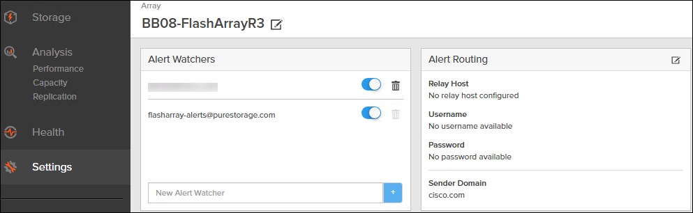
The Relay Host section displays the hostname or IP address of an SMTP relay host if one is configured for the array. If you specify a relay host, Purity routes the email messages via the relay (mail forwarding) address rather than sending them directly to the alert recipient addresses.
In the Sender Domain section, the sender domain determines how Purity logs are parsed and treated by Pure Storage Support and Escalations. By default, the sender domain is set to the domain name please-configure.me.
It is crucial that you set the sender domain to the correct domain name. If the array is not a Pure Storage test array, set the sender domain to the actual customer domain name. For example, mycompany.com.
The Pure1 Support section manages settings for Phone Home, Remote Assist, and Support Logs.
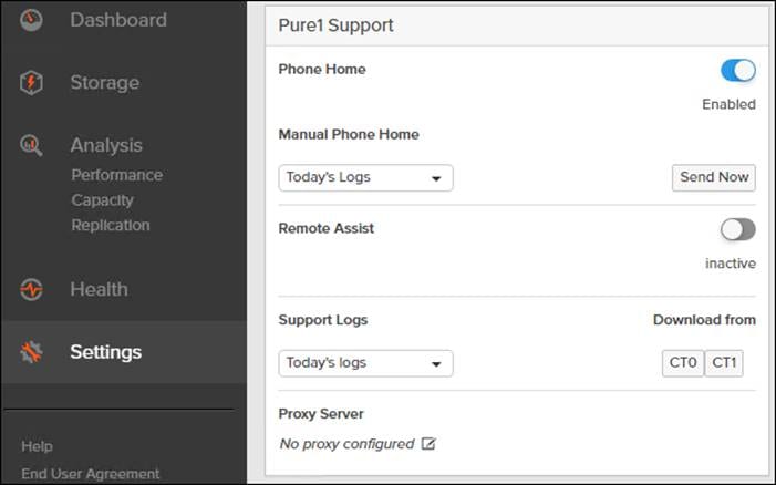
The phone home facility provides a secure direct link between the array and the Pure Storage Technical Support web site. The link is used to transmit log contents and alert messages to the Pure Storage Support team so that when diagnosis or remedial action is required, complete recent history about array performance and significant events is available. By default, the phone home facility is enabled. If the phone home facility is enabled to send information automatically, Purity transmits log and alert information directly to Pure Storage Support via a secure network connection. Log contents are transmitted hourly and stored at the support web site, enabling detection of array performance and error rate trends. Alerts are reported immediately when they occur so that timely action can be taken.
Phone home logs can also be sent to Pure Storage Technical support on demand, with options including Today's Logs, Yesterday's Logs, or All Log History.
The Remote Assist section displays the remote assist status as "Connected" or "Disconnected". By default, remote assist is disconnected. A connected remote assist status means that a remote assist session has been opened, allowing Pure Storage Support to connect to the array. Disconnect the remote assist session to close the session.
The Support Logs section allows you to download the Purity log contents of the specified controller to the current administrative workstation. Purity continuously logs a variety of array activities, including performance summaries, hardware and operating status reports, and administrative actions.
Configure DNS Server IP Addresses
To configure the DNS server IP address, follow these steps:
1. Click Settings > Network.
2. In the DNS section, hover over the domain name and click the pencil icon. The Edit DNS dialog box appears.
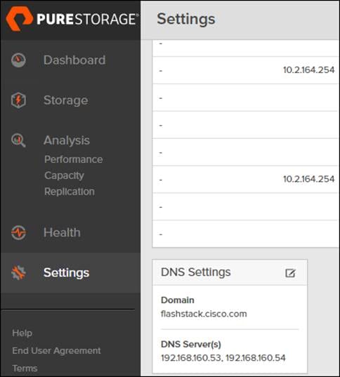
3. Complete the following fields:
a. Domain: Specify the domain suffix to be appended by the array when doing DNS lookups.
b. NS#: Specify up to three DNS server IP addresses for Purity to use to resolve hostnames to IP addresses. Enter one IP address in each DNS# field. Purity queries the DNS servers in the order that the IP addresses are listed.
4. Click Save.
The Directory Service manages the integration of FlashArray with an existing directory service. When the Directory Service sub-view is configured and enabled, the FlashArray leverages a directory service to perform user account and permission level searches. Configuring directory services is OPTIONAL.
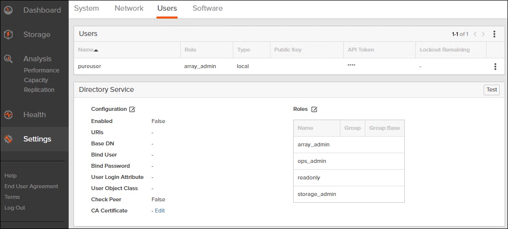
The FlashArray is delivered with a single local user, named pureuser, with array-wide (Array Admin) permissions.
To support multiple FlashArray users, integrate the array with a directory service, such as Microsoft Active Directory or OpenLDAP.
Role-based access control is achieved by configuring groups in the directory that correspond to the following permission groups (roles) on the array:
● Read Only Group. Read Only users have read-only privilege to run commands that convey the state of the array. Read Only uses cannot alter the state of the array.
● Storage Admin Group. Storage Admin users have all the privileges of Read Only users, plus the ability to run commands related to storage operations, such as administering volumes, hosts, and host groups. Storage Admin users cannot perform operations that deal with global and system configurations.
● Array Admin Group. Array Admin users have all the privileges of Storage Admin users, plus the ability to perform array-wide changes. In other words, Array Admin users can perform all FlashArray operations.
1. Click Settings > Users.
2. Click the icon in the Directory Services panel
a. Enabled: Check the box to leverage the directory service to perform user account and permission level searches.
b. URI: Enter the comma-separated list of up to 30 URIs of the directory servers. The URI must include a URL scheme (ldap, or ldaps for LDAP over SSL), the hostname, and the domain. You can optionally specify a port. For example, ldap://ad.company.com configures the directory service with the hostname "ad" in the domain "company.com" while specifying the unencrypted LDAP protocol.
c. Base DN: Enter the base distinguished name (DN) of the directory service. The Base DN is built from the domain and should consist only of domain components (DCs). For example, for ldap://ad.storage.company.com, the Base DN would be: “DC=storage,DC=company,DC=com”
d. Bind User: Username used to bind to and query the directory. For Active Directory, enter the username - often referred to as sAMAccountName or User Logon Name - of the account that is used to perform directory lookups. The username cannot contain the characters " [ ] : ; | = + * ? < > / \ and cannot exceed 20 characters in length. For OpenLDAP, enter the full DN of the user. For example, "CN=John,OU=Users,DC=example,DC=com".
e. Bind Password: Enter the password for the bind user account.
f. Group Base: Enter the organizational unit (OU) to the configured groups in the directory tree. The Group Base consists of OUs that, when combined with the base DN attribute and the configured group CNs, complete the full Distinguished Name of each groups. The group base should specify "OU=" for each OU and multiple OUs should be separated by commas. The order of OUs should get larger in scope from left to right. In the following example, SANManagers contains the sub-organizational unit PureGroups: "OU=PureGroups,OU=SANManagers".
g. Array Admin Group: Common Name (CN) of the directory service group containing administrators with full privileges to manage the FlashArray. Array Admin Group administrators have the same privileges as pureuser. The name should be the Common Name of the group without the "CN=" specifier. If the configured groups are not in the same OU, also specify the OU. For example, "pureadmins,OU=PureStorage", where pureadmins is the common name of the directory service group.
h. Storage Admin Group: Common Name (CN) of the configured directory service group containing administrators with storage related privileges on the FlashArray. The name should be the Common Name of the group without the "CN=" specifier. If the configured groups are not in the same OU, also specify the OU. For example, "pureusers,OU=PureStorage", where pureusers is the common name of the directory service group.
i. Read Only Group: Common Name (CN) of the configured directory service group containing users with read-only privileges on the FlashArray. The name should be the Common Name of the group without the "CN=" specifier. If the configured groups are not in the same OU, also specify the OU. For example, "purereadonly,OU=PureStorage", where purereadonly is the common name of the directory service group.
j. Check Peer: Check the box to validate the authenticity of the directory servers using the CA Certificate. If you enable Check Peer, you must provide a CA Certificate.
k. CA Certificate: Enter the certificate of the issuing certificate authority. Only one certificate can be configured at a time, so the same certificate authority should be the issuer of all directory server certificates. The certificate must be PEM formatted (Base64 encoded) and include the "-----BEGIN CERTIFICATE-----" and "-----END CERTIFICATE-----" lines. The certificate cannot exceed 3000 characters in total length.
3. Click Save.
4. Click Test to test the configuration settings. The LDAP Test Results pop-up window appears. Green squares represent successful checks. Red squares represent failed checks.
Self-Signed Certificate
Purity creates a self-signed certificate and private key when you start the system for the first time. The SSL Certificate sub-view allows you to view and change certificate attributes, create a new self-signed certificate, construct certificate signing requests, import certificates and private keys, and export certificates.
Creating a self-signed certificate replaces the current certificate. When you create a self-signed certificate, include any attribute changes, specify the validity period of the new certificate, and optionally generate a new private key.
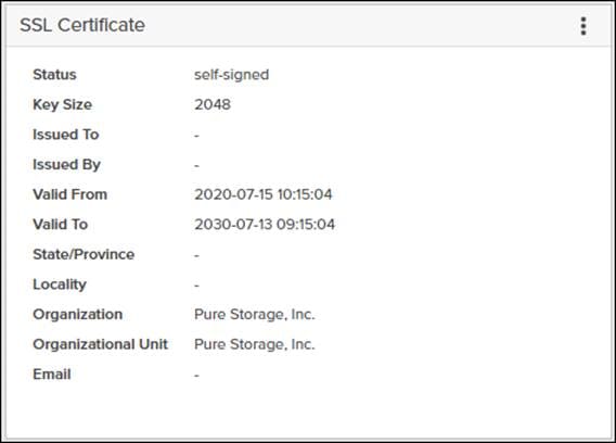
When you create the self-signed certificate, you can generate a private key and specify a different key size. If you do not generate a private key, the new certificate uses the existing key.
You can change the validity period of the new self-signed certificate. By default, self-signed certificates are valid for 3650 days
CA-Signed Certificate
Certificate authorities (CA) are third party entities outside the organization that issue certificates. To obtain a CA certificate, you must first construct a certificate signing request (CSR) on the array.
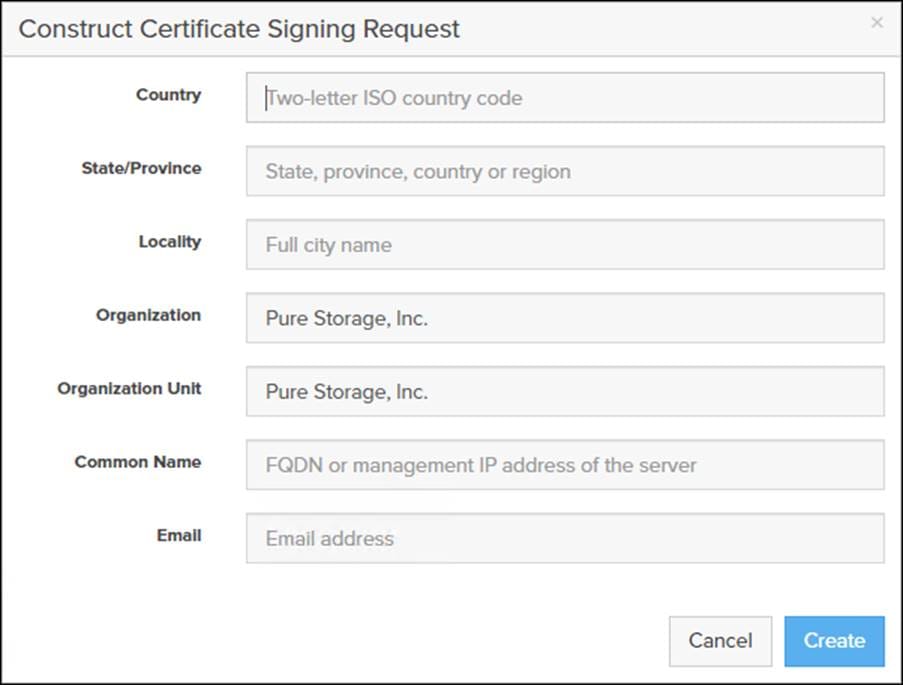
The CSR represents a block of encrypted data specific to your organization. You can change the certificate attributes when you construct the CSR; otherwise, Purity will reuse the attributes of the current certificate (self-signed or imported) to construct the new one. Note that the certificate attribute changes will only be visible after you import the signed certificate from the CA.
Send the CSR to a certificate authority for signing. The certificate authority returns the SSL certificate for you to import. Verify that the signed certificate is PEM formatted (Base64 encoded), includes the "-----BEGIN CERTIFICATE-----" and "-----END CERTIFICATE-----" lines, and does not exceed 3000 characters in total length. When you import the certificate, also import the intermediate certificate if it is not bundled with the CA certificate.
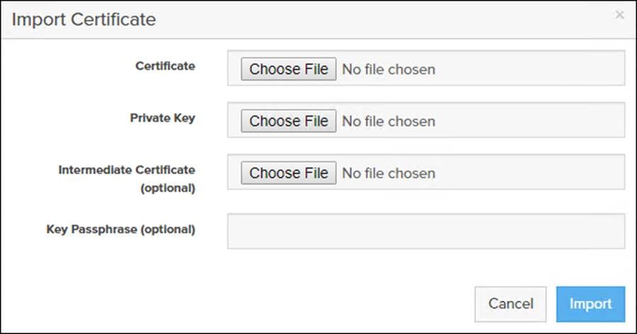
If the certificate is signed with the CSR that was constructed on the current array and you did not change the private key, you do not need to import the key. However, if the CSR was not constructed on the current array or if the private key has changed since you constructed the CSR, you must import the private key. If the private key is encrypted, also specify the passphrase.
iSCSI Interface Configuration
The iSCSI traffic will be carried on two VLANs, A (901) and B (902) that are configured in our example with the following values:
Table 11. iSCSI A FlashArray//X50 R2 Interface Configuration Settings
| Device |
Interface |
IP |
Netmask |
| FlashArray//X50 R3 Controller 0 |
CT0.ETH4 |
192.168.101.146 |
255.255.255.0 |
| FlashArray//X50 R3 Controller 1 |
CT0.ETH4 |
192.1668.101.147 |
255.255.255.0 |
Table 12. iSCSI C FlashArray//X50 R2 Interface Configuration Settings
| Device |
Interface |
IP |
Netmask |
| FlashArray//X50 R3 Controller 0 |
CT0.ETH5 |
192.168.102.146 |
255.255.255.0 |
| FlashArray//X50 R3 Controller 1 |
CT0.ETH5 |
192.168.102.147 |
255.255.255.0 |
To configure iSCSI interfaces for environments deploying iSCSI boot LUNs and/or datastores, follow these steps:
1. Click Settings > Network.
2. Click the Edit Icon for interface CT0.eth4.
3. Click Enable and add the IP information from Table 7 and set the MTU to 900.
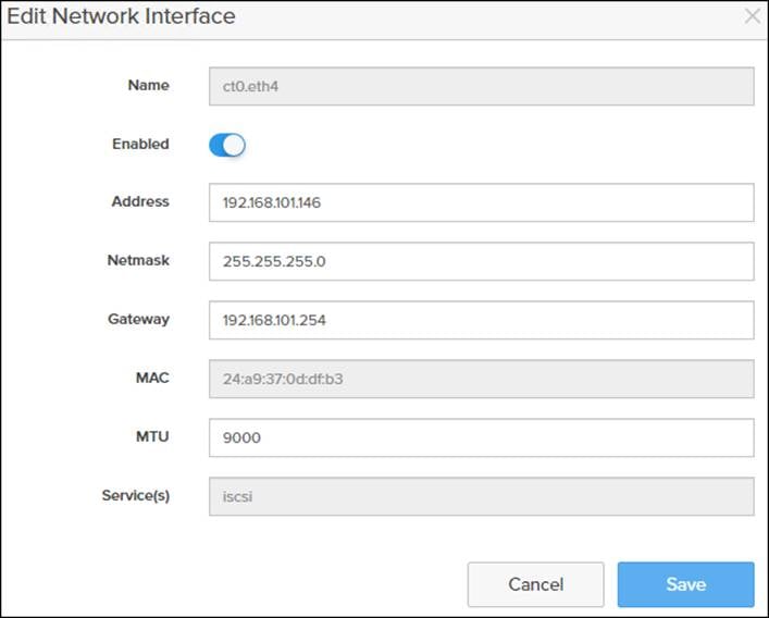
4. Click Save.
5. Repeat Steps 1-4 for CT0.eth5, CT1.eth4, and CT1.eth5.
Claim FlashArray//X in Intersight (optional)
Claiming a Pure Storage FlashArray or VMware vCenter in Cisco Intersight requires the use of an Intersight Assist virtual machine. Refer to the following if link if there isn’t an Intersight Assist system in your environment: https://www.cisco.com/c/en/us/td/docs/unified_computing/Intersight/cisco-intersight-assist-getting-started-guide/m-installing-cisco-intersight-assist.html
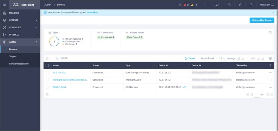
To claim FlashArray//X in Intersight, follow these steps:
1. Open a browser to Cisco Intersight, https://intersight.com and log into your Intersight account.
2. Click Admin > Devices.

3. Click Claim a New Device and choose Claim Though Intersight Assist.
4. Set Type to Pure Storage FlashArray.
5. Enter FlashArray Hostname/ IP address and credentials.
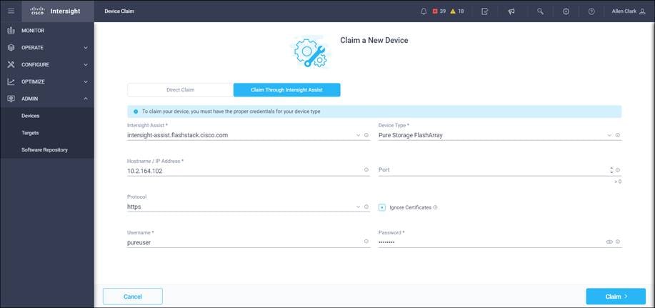
6. Click Claim.
The following procedures describe how to configure the Cisco UCS domain for use in a base FlashStack environment. This procedure assumes you’re using Cisco UCS Fabric Interconnects running 4.1(2a). Configuration on a differing model of Cisco UCS Fabric Interconnects should be comparable but may differ slightly with model and changes in the Cisco UCS Manager release. The Cisco USC 6454 Fabric Interconnects and Cisco UCS Manger 4.1(2a) release were used to validate this FlashStack solution, so the configuration steps will reflect this model and release.
Figure 4. Cisco UCS Configuration Workflow
Physical cabling should be completed by following the diagram and table references in section Physical Topology.
Cisco UCS Basic System Configuration Dialog
This section provides detailed instructions for the configuration of the Cisco UCS 6454 Fabric Interconnects used in this FlashStack solution. Some changes may be appropriate for a customer’s environment but be careful when stepping outside of these instructions as it may lead to an improper configuration.
Cisco UCS Fabric Interconnect A
To set up the initial configuration for the Cisco Fabric Interconnect A, follow these steps:
1. Configure the Fabric Interconnect
---- Basic System Configuration Dialog ----
Enter the configuration method. (console/gui) ? console
Enter the setup mode; setup newly or restore from backup. (setup/restore) ? setup
You have chosen to setup a new Fabric interconnect. Continue? (y/n): y
Enforce strong password? (y/n) [y]: enter
Enter the password for "admin": <<password>>
Confirm the password for "admin": <<password>>
Is this Fabric interconnect part of a cluster(select 'no' for standalone)? (yes/no) [n]: yes
Enter the switch fabric (A/B) []: A
Enter the system name: <var_ucs_clustername>>
Physical Switch Mgmt0 IP address : <<var_ucs_a_mgmt_ip>>
Physical Switch Mgmt0 IPv4 netmask : <<var_oob_mgmt_mask>>
IPv4 address of the default gateway : <<var_oob_gateway>>
Cluster IPv4 address : <<var_ucs_mgmt_vip>
Configure the DNS Server IP address? (yes/no) [n]: yes
DNS IP address : <<var_nameserver_ip>>
Configure the default domain name? (yes/no) [n]: yes
Default domain name : <<var_dns_domain_name>>
Join centralized management environment (UCS Central)? (yes/no) [n]: noConfigure
Would you like to edit the configuration? (yes/no) [n]: Enter
2. Review the configuration summary before enabling the configuration.
Apply and save the configuration (select 'no' if you want to re-enter)? (yes/no):yes
Cisco UCS Fabric Interconnect A
To set up the initial configuration for the Cisco Fabric Interconnect A, follow these steps:
1. Configure the Fabric Interconnect.
---- Basic System Configuration Dialog ----
Enter the configuration method. (console/gui) ? console
Installer has detected the presence of a peer Fabric interconnect. This Fabric interconnect will be added to the cluster. Continue (y/n) ? y
Physical Switch Mgmt0 IP address : <<var_ucs_a_mgmt_ip>>
2. Review the configuration summary before enabling the configuration.
Apply and save the configuration (select 'no' if you want to re-enter)? (yes/no):yes
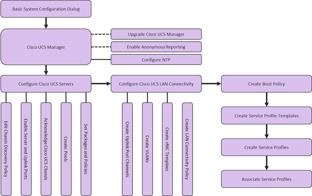
Cisco UCS Manager Configuration
To log into the Cisco Unified Computing System (UCS) environment, follow these steps:
1. Open a web browser and navigate to the Cisco UCS fabric interconnect cluster address.
2. Click the Launch UCS Manager link within the opening page.
3. If prompted to accept security certificates, accept as necessary.
4. When the UCS Manager login is prompted, enter admin for the user name and enter the administrative password.
5. Click Login to log into Cisco UCS Manager.
Upgrade Cisco UCS Manager to Version 4.1(2a)
This document assumes the use of Cisco UCS 4.1(2a). To upgrade the Cisco UCS Manager software and the Cisco UCS Fabric Interconnect software to version 4.1(2a), refer to Cisco UCS Manager Install and Upgrade Guides.
During the first connection to the Cisco UCS Manager GUI, a pop-up window will appear to allow for the configuration of Anonymous Reporting to Cisco on use to help with future development. To create anonymous reporting, follow this step:
1. In the Anonymous Reporting window, choose whether to send anonymous data to Cisco for improving future products and provide the appropriate SMTP server gateway information:
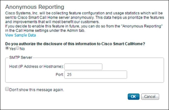
If you want to enable or disable Anonymous Reporting at a later date, it can be found within Cisco UCS Manager under: Admin -> Communication Management -> Call Home, which has a tab on the far right for Anonymous Reporting.
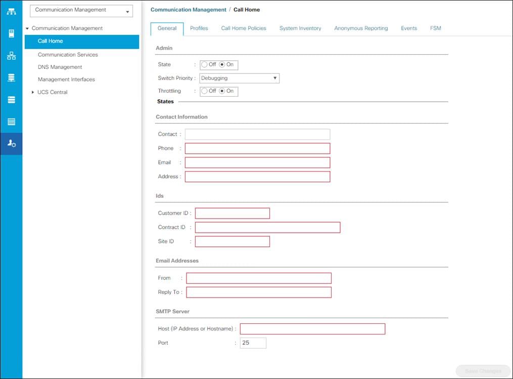
During the first connection to the Cisco UCS Manager GUI, a pop-up window will appear to allow for the configuration of Anonymous Reporting to Cisco on use to help with future development. To create anonymous reporting, follow this step:
1. In Cisco UCS Manager, click the Admin tab in the navigation pane.
2. Expand Communication Management and click Call Home.
3. Change State to On.
4. Fill in the fields according to your preferences and click Save Changes and OK.
To synchronize the Cisco UCS environment to the NTP server, follow these steps:
1. In Cisco UCS Manager, click the Admin tab in the navigation pane.
2. Expand Timezone Management and click Timezone.
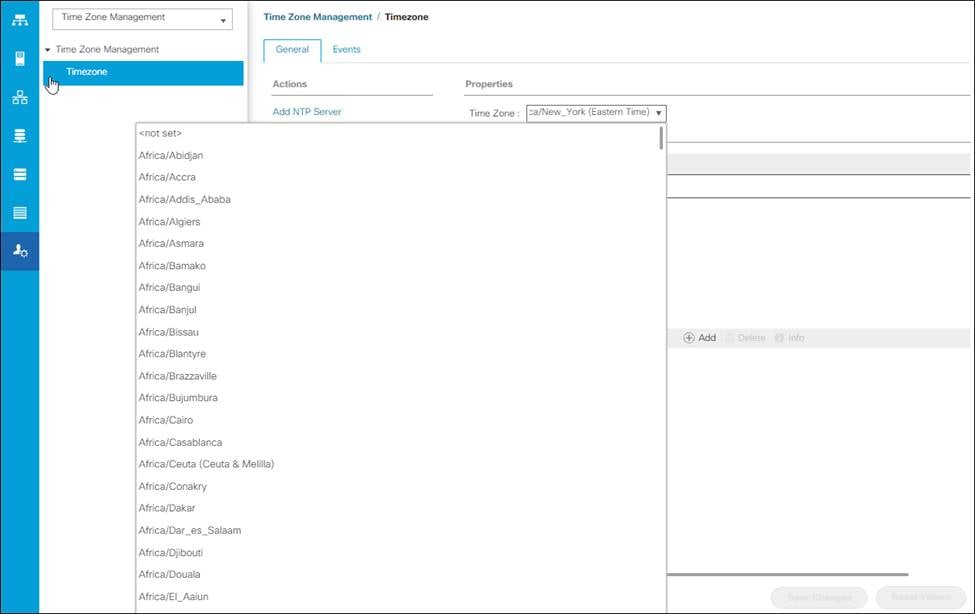
3. In the Properties pane, choose the appropriate time zone in the Timezone menu.
4. Click Save Changes and then click OK.
5. Click Add NTP Server.
6. Enter <<var_oob_ntp>> and click OK.
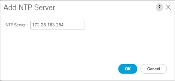
7. Click OK.
Setting the discovery policy simplifies the addition of B-Series Cisco UCS chassis. To modify the chassis discovery policy, follow these steps:
1. In Cisco UCS Manager, click the Equipment tab in the navigation pane and choose Policies from the drop-down list.
2. Under Global Policies, set the Chassis/FEX Discovery Policy to match the number of uplink ports that are cabled between the chassis or fabric extenders (FEXes) and the fabric interconnects.
3. Set the Link Grouping Preference to Port Channel.
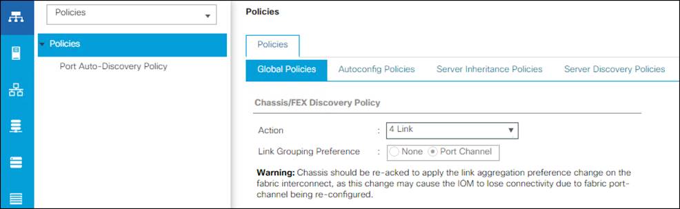
4. Leave other settings alone or change if appropriate to your environment.
5. Click Save Changes.
6. Click OK.
Enable Server and Uplink Ports
To enable server and uplink ports, follow these steps:
1. In Cisco UCS Manager, click the Equipment tab in the navigation pane.
2. Select Equipment > Fabric Interconnects > Fabric Interconnect A (primary) > Fixed Module.
3. Expand Ethernet Ports.
4. Choose the ports that are connected to the 2408, C4200 Servers, and/or C Series Servers , right-click them, and choose “Configure as Server Port.”
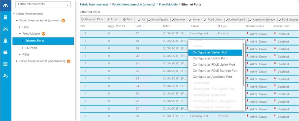
5. Click Yes to confirm server ports and click OK.
6. Verify that the ports connected to the chassis are now configured as server ports.
7. Choose ports 49 and 50 that are connected to the Cisco Nexus switches, right-click them, and choose Configure as Uplink Port.
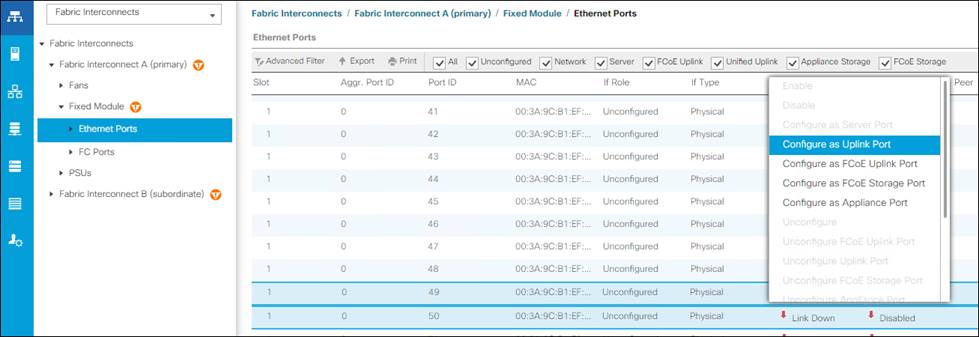
8. Click Yes to confirm uplink ports and click OK.
9. Click Equipment > Fabric Interconnects > Fabric Interconnect B (subordinate) > Fixed Module.
10. Expand Ethernet Ports.
11. Select the ports that are connected to the chassis, right-click them and click Configure as Server Port.
12. Click Yes to confirm server ports and click OK.
13. Select ports 39 and 40 that are connected to the Cisco Nexus switches, right-click them, and click Configure as Uplink Port.
14. Click Yes to confirm the uplink ports and click OK.
To acknowledge all Cisco UCS chassis, follow these steps:
1. In Cisco UCS Manager, click the Equipment tab in the navigation pane.
2. Expand Chassis and select each chassis that is listed.
3. Right-click each chassis and choose Acknowledge Chassis.
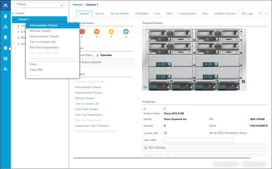
4. Click Yes and then click OK to complete acknowledging the chassis.
Create MAC Address Pools
To configure the necessary MAC address pools for the Cisco UCS environment, follow these steps:
1. In Cisco UCS Manager, click the LAN tab in the navigation pane.
2. Click Pools > root.
![]() In this procedure, two MAC address pools are created, one for each switching fabric.
In this procedure, two MAC address pools are created, one for each switching fabric.
3. Right-click MAC Pools under the root organization.
4. Click Create MAC Pool to create the MAC address pool.
5. Enter MAC_Pool_A for the name of the MAC pool.
6. Optional: Enter a description for the MAC pool.
7. Choose Sequential for the option for Assignment Order.
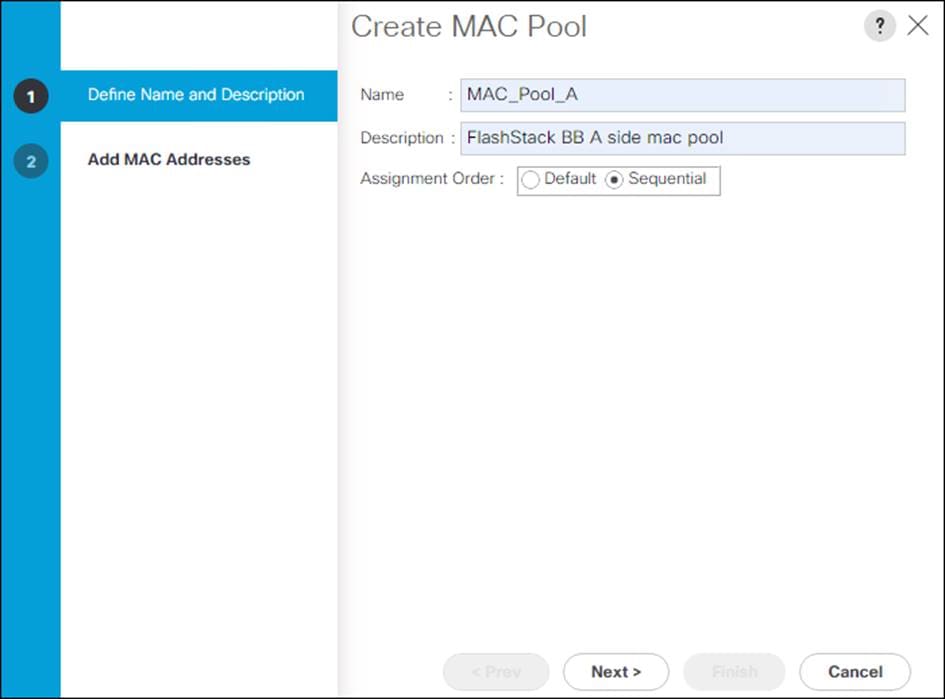
8. Click Next.
9. Click Add.
10. Specify a starting MAC address.
![]() For Cisco UCS deployments, the recommendation is to place 0A in the next-to-last octet of the starting MAC address to identify all the MAC addresses as fabric A addresses. In our example, we have carried forward the of also embedding the extra building, floor and Cisco UCS domain number information giving us 00:25:B5:91:1A:00 as our first MAC address.
For Cisco UCS deployments, the recommendation is to place 0A in the next-to-last octet of the starting MAC address to identify all the MAC addresses as fabric A addresses. In our example, we have carried forward the of also embedding the extra building, floor and Cisco UCS domain number information giving us 00:25:B5:91:1A:00 as our first MAC address.
11. Specify a size for the MAC address pool that is enough to support the available blade or server resources.

12. Click OK.
13. Click Finish.
14. In the confirmation message, click OK.
15. Right-click MAC Pools under the root organization.
16. Click Create MAC Pool to create the MAC address pool.
17. Enter MAC_Pool_B for the name of the MAC pool.
18. Optional: Enter a description for the MAC pool.
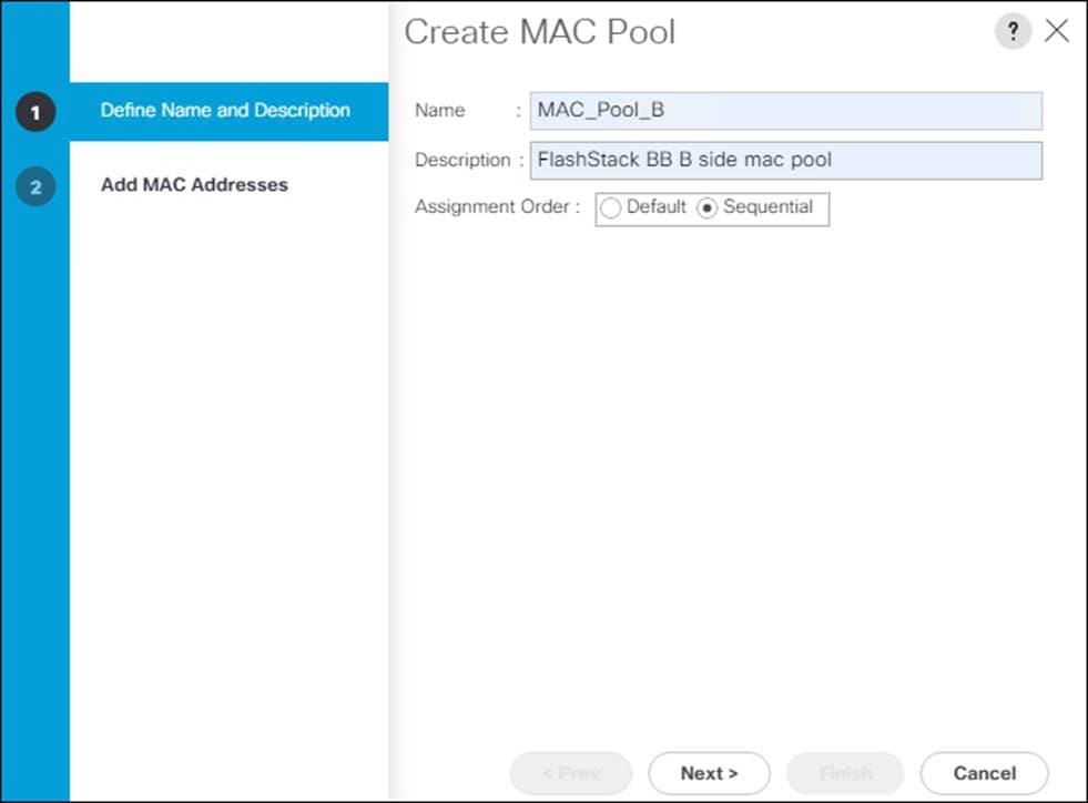
19. Click Next.
20. Click Add.
21. Specify a starting MAC address.
![]() For Cisco UCS deployments, the recommendation is to place 0B in the next-to-last octet of the starting MAC address to identify all the MAC addresses as fabric B addresses. In our example, we have carried forward the of also embedding the extra building, floor and Cisco UCS domain number information giving us 00:25:B5:91:1B:00 as our first MAC address.
For Cisco UCS deployments, the recommendation is to place 0B in the next-to-last octet of the starting MAC address to identify all the MAC addresses as fabric B addresses. In our example, we have carried forward the of also embedding the extra building, floor and Cisco UCS domain number information giving us 00:25:B5:91:1B:00 as our first MAC address.
22. Specify a size for the MAC address pool that is sufficient to support the available blade or server resources.
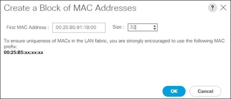
23. Click OK.
24. Click Finish.
25. In the confirmation message, click OK.
Create UUID Suffix Pool
To configure the necessary universally unique identifier (UUID) suffix pool for the Cisco UCS environment, follow these steps:
1. In Cisco UCS Manager, click the Servers tab in the navigation pane.
2. Click Pools > root.
3. Right-click UUID Suffix Pools.
4. Click Create UUID Suffix Pool.
5. Enter UUID_Pool for the name of the UUID suffix pool.
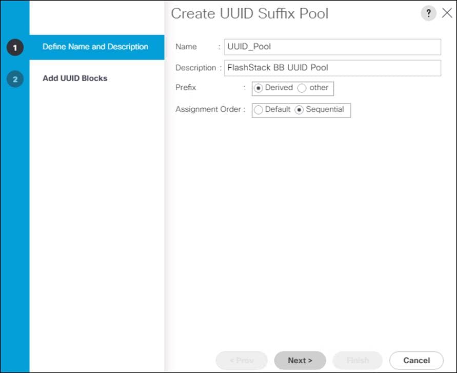
6. Optional: Enter a description for the UUID suffix pool.
7. Keep the prefix at the derived option.
8. Click Sequential for the Assignment Order.
9. Click Next.
10. Click Add to add a block of UUIDs.
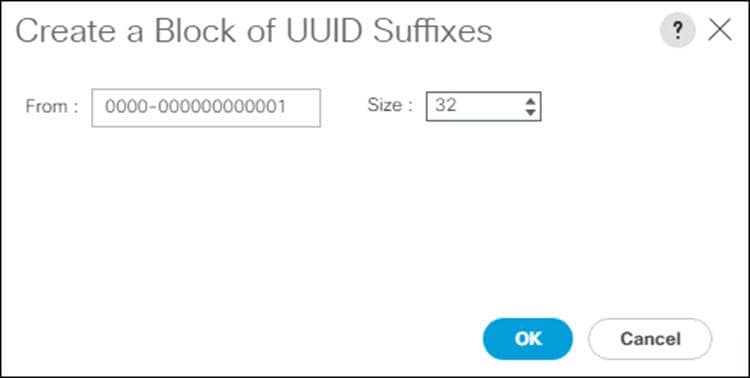
11. Keep the From: field at the default setting.
12. Specify a size for the UUID block that is enough to support the available blade or server resources.
13. Click OK.
14. Click Finish.
15. Click OK.
Create Server Pool
To configure the necessary server pool for the Cisco UCS environment, follow these steps:
1. In Cisco UCS Manager, click the Servers tab in the navigation pane.
2. Click Pools > root.
3. Right-click Server Pools.
4. Click Create Server Pool.
5. Enter AMD_Pool for the name of the server pool.
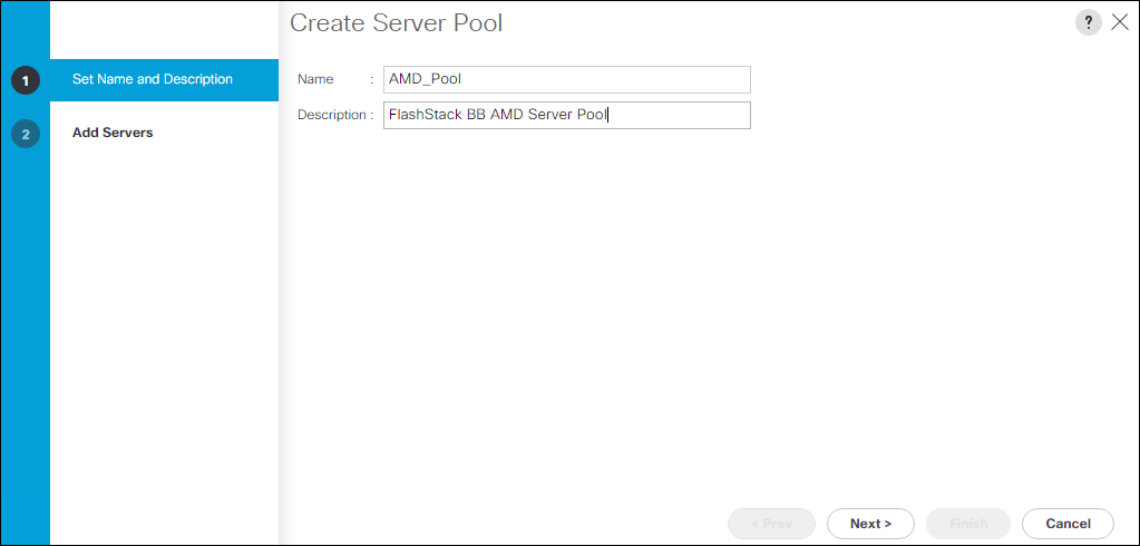
6. Optional: Enter a description for the server pool.
7. Click Next.
8. Choose two (or more) servers to be used for the VMware management cluster and click >> to add them to AMD_Pool server pool.
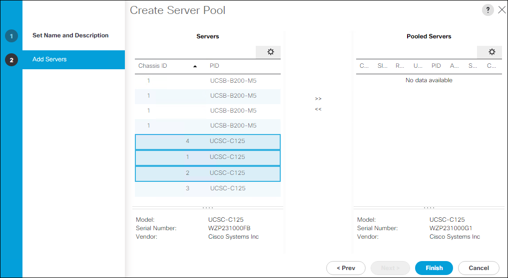
9. Click Finish.
10. Click OK
![]() Cisco UCS Domains with both AMD and Intel based servers should have separate server pools for each server type.
Cisco UCS Domains with both AMD and Intel based servers should have separate server pools for each server type.
Create IQN Pool for iSCSI Boot
To configure the IQP pool for iSCSI boot, follow these steps:
1. In Cisco UCS Manager, click the SAN tab in the navigation pane.
2. Selection Pools > root.
3. Right-click IQN pools.
4. Click Create IQN Suffix Pool.
5. Enter IQN-Pool for the name of the IQN pool.
6. Optional: Enter a description for the IQN Pool.
7. Enter iqn.1992-08.com.cisco for the Prefix.
8. Click Sequential for Assignment Order.
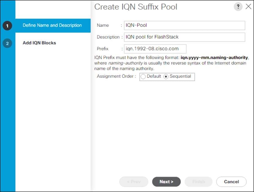
9. Click Next.
10. Click Add.
11. Enter ucs-host for the suffix.
12. Enter 1 in the From field.
13. Specify the size of the IQN block large enough to support the planned server resources.
14. Click OK.
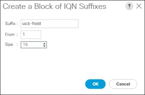
15. Click Finish.
Create IP Pool for KVM Access
To create a block of IP addresses for in band server Keyboard, Video, Mouse (KVM) access in the Cisco UCS environment, follow these steps:
1. In Cisco UCS Manager, click the LAN tab in the navigation pane.
2. Click Pools > root > IP Pools.
3. Right-click IP Pool ext-mgmt and choose Create Block of IPv4 Addresses.
4. Enter the starting IP address of the block and the number of IP addresses required, and the subnet and gateway information.
5. Click OK to create the block of IPs.
6. Click OK.
Create IP Pools for iSCSI Boot
To configure the IP pools for iSCSI boot, follow these steps:
1. In Cisco UCS Manager, click the LAN tab in the navigation pane.
2. Selection Pools > root.
3. Right-click IP Pools.
4. Click Create IP Pool.
5. Enter iSCSI-IP-Pool-A for the name.
6. Option: Enter a description:
7. Click Sequential for the assignment order.
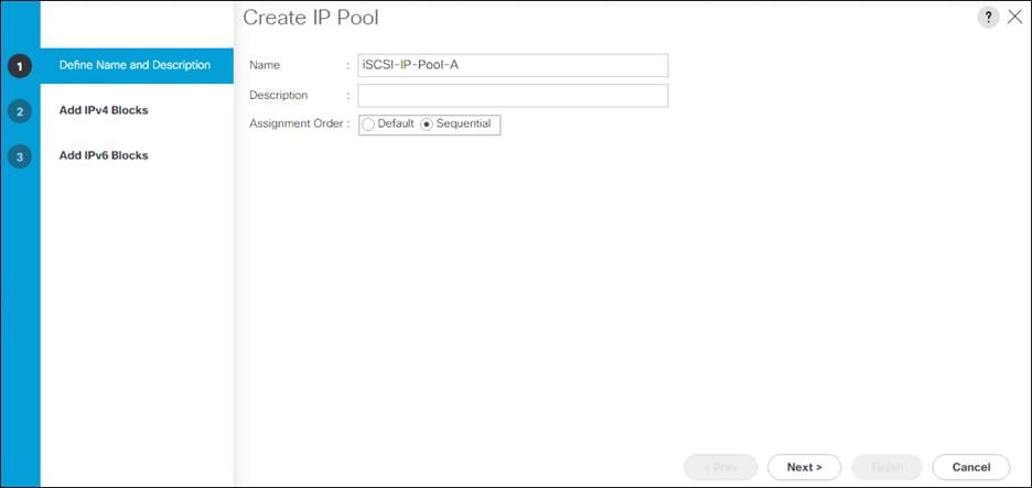
8. Click Next.
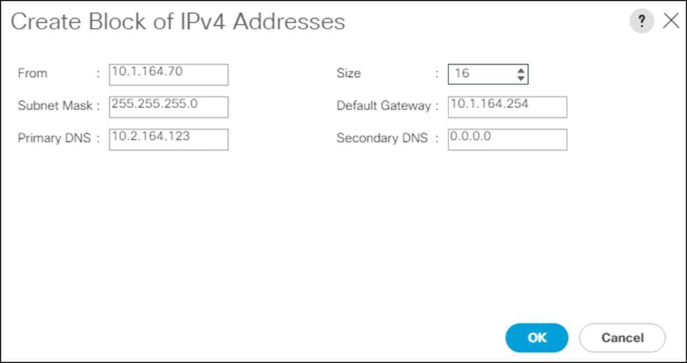
9. Click Add to add a block of IP address.
10. In the From field, enter the first IP address for the iSCSI range.
11. Set the size large enough to support the planned server resources.
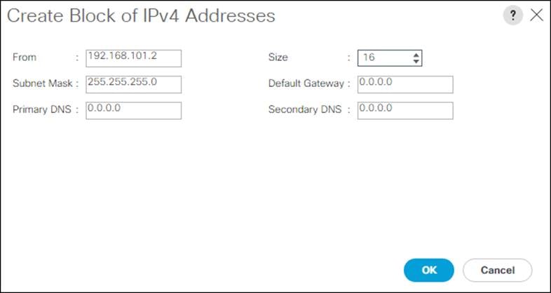
12. Click OK.
13. Click Next.
14. Click Finish.
15. Right click IP Pools.
16. Click Create IP Pool.
17. Enter iSCSI-IP-Pool-B for the name.
18. Option: Enter a description.
19. Click Sequential for the assignment order.
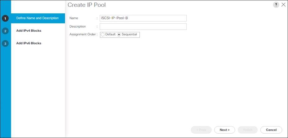
20. Click Next.
21. Click Add to add a block of IP address.
22. In the From field, enter the first IP address for the iSCSI range.
23. Set the size large enough to support the planned server resources.
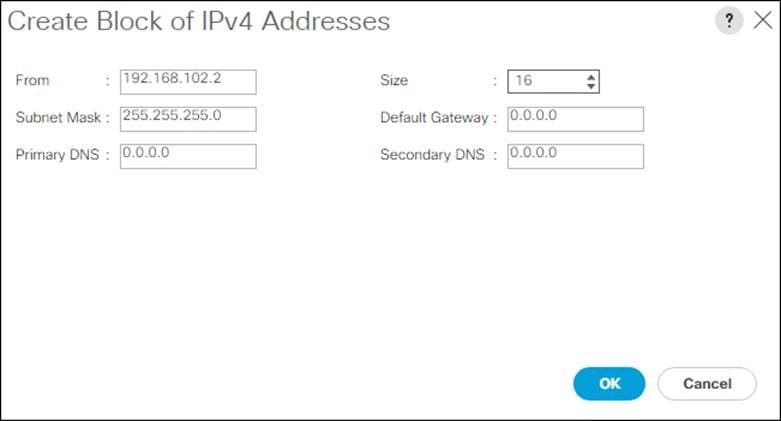
24. Click OK.
25. Click Next.
26. Click Finish.
Create Host Firmware Package
Firmware management policies allow the administrator to select the corresponding packages for a given server configuration. These policies often include packages for adapter, BIOS, board controller, FC adapters, host bus adapter (HBA) option ROM, and storage controller properties.
To create a firmware management policy for a given server configuration in the Cisco UCS environment, follow these steps:
1. In Cisco UCS Manager, click the Servers tab in the navigation pane.
2. Click Policies > root.
3. Expand Host Firmware Packages.
4. Click Default.
5. In the Actions pane, click Modify Package Versions.
6. Choose the version 4.1(2a)B for the Blade Package, and optionally set version 4.1(2a)C for the Rack Package.
7. Leave Excluded Components with only Local Disk selected.
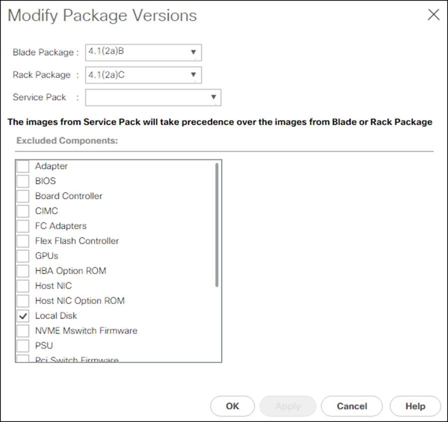
8. Click OK to modify the host firmware package.
Create Server Pool Qualification Policy (Optional)
To create an optional server pool qualification policy for the Cisco UCS environment, follow these steps:
![]() This example creates a policy for Cisco UCS C125 M5 servers for a server pool.
This example creates a policy for Cisco UCS C125 M5 servers for a server pool.
1. In Cisco UCS Manager, click the Servers tab in the navigation pane.
2. Click Policies > root.
3. Right-click Server Pool Policy Qualifications.
4. Click Create Server Pool Policy Qualification.
5. Name the policy UCS-C125-M5.
6. Click Create Server PID Qualifications.
7. Click UCSC-125 from the PID drop-down list.
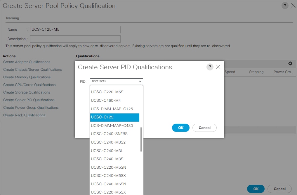
8. Click OK.
9. Optionally, choose additional qualifications to refine server selection parameters for the server pool.
10. Click OK to create the policy then OK for the confirmation.
![]() Cisco UCS Domains with both AMD and Intel based servers should have separate server pool policy qualifications for each server type.
Cisco UCS Domains with both AMD and Intel based servers should have separate server pool policy qualifications for each server type.
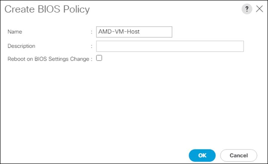
Create Server BIOS Policy
To create a server BIOS policy for the Cisco UCS environment, follow these steps:
1. In Cisco UCS Manager, click Servers..
2. Click Policies > root.
3. Right-click BIOS Policies.
4. Click Create BIOS Policy.
5. Enter AMD-VM-Host for the BIOS policy name.
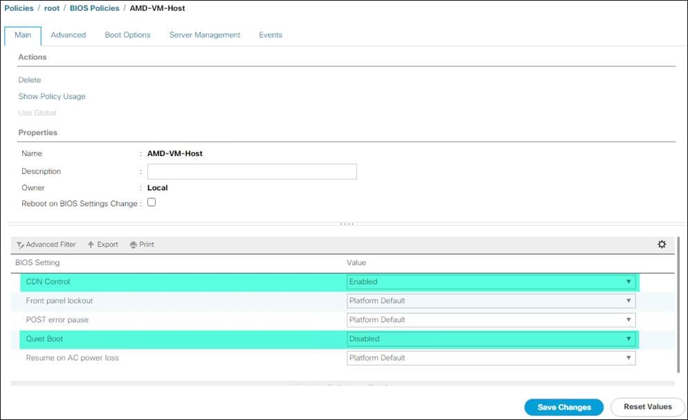
6. Click the newly created BIOS Policy.
7. Within the Main tab of the Policy:
a. Change CDN Control to enabled.
b. Change the Quiet Boot setting to disabled.
8. Click the Advanced tab, leaving the Processor tab selected within the Advanced tab.
9. Set the following within the Processor tab:
a. Core Performance Boost -> Auto
b. Global C-state Control -> Disabled
c. L1 Stream HW Prefetcher -> Enabled
d. L2 Stream HW Prefetcher -> Enabled
e. Determinism Slider -> Power
f. IOMMU -> Enabled
g. AMD Memory Interleaving -> Auto
h. AMD Memory Interleaving Size -> Auto
i. SMEE -> Enabled
j. SMT Mode -> Auto
k. SVM Mode -> Enabled
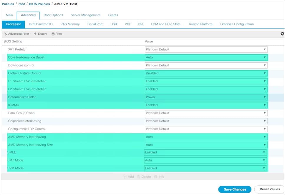
10. Click Save Changes.
11. Click OK.
![]() For more information, see Performance Tuning for Cisco UCS C125 Rack Server Nodes with AMD Processors.
For more information, see Performance Tuning for Cisco UCS C125 Rack Server Nodes with AMD Processors.
Update Default Maintenance Policy
To update the default Maintenance Policy, follow these steps:
1. In Cisco UCS Manager, click the Servers tab in the navigation pane.
2. Click Policies > root.
3. Click Maintenance Policies > default.
4. Change the Reboot Policy to User Ack.
5. (Optional: Click “On Next Boot” to delegate maintenance windows to server owners).
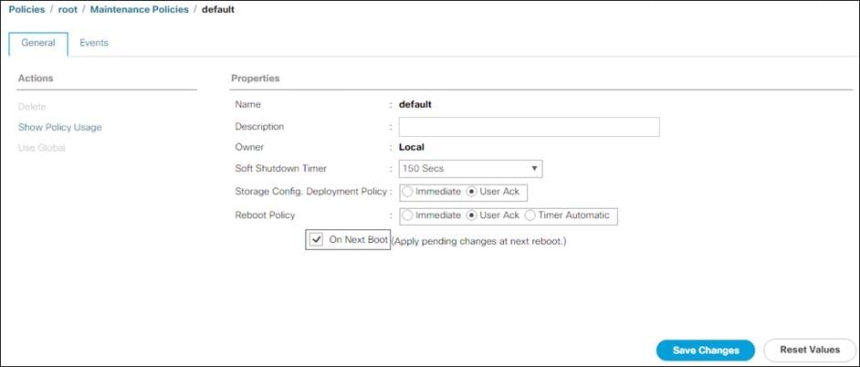
6. Click Save Changes.
7. Click OK to accept the change.
Create Local Disk Configuration Policy (Optional)
A local disk configuration for the Cisco UCS environment is necessary if the servers in the environment do not have a local disk.
![]() This policy should not be used on servers that contain local disks.
This policy should not be used on servers that contain local disks.
To create a local disk configuration policy, follow these steps:
1. In Cisco UCS Manager, click the Servers tab in the navigation pane.
2. Click Policies > root.
3. Right-click Local Disk Config Policies.
4. Click Create Local Disk Configuration Policy.
5. Enter SAN-Boot for the local disk configuration policy name.
6. Change the mode to No Local Storage.
7. Click OK to create the local disk configuration policy.
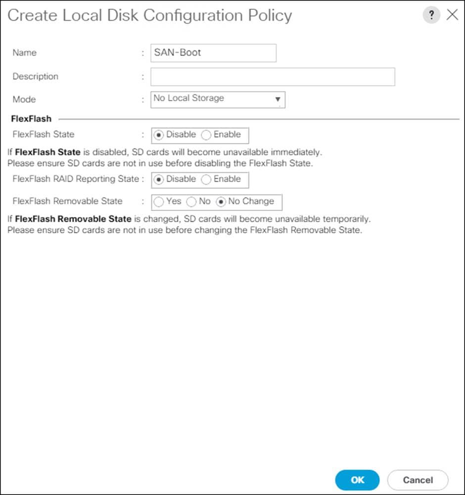
8. Click OK.
Create Power Control Policy
To create a power control policy for the Cisco UCS environment, follow these steps:
1. In Cisco UCS Manager, click the Servers tab in the navigation pane.
2. Click Policies > root.
3. Right-click Power Control Policies.
4. Click Create Power Control Policy.
5. Enter No-Power-Cap for the power control policy name.
6. Change the power capping setting to No Cap.
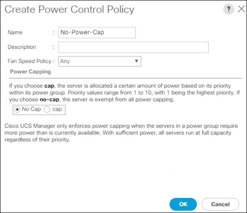
7. Click OK to create the power control policy.
8. Click OK.
Create Network Control Policy for Cisco Discovery Protocol
To create a network control policy that enables Cisco Discovery Protocol (CDP) on virtual network ports, follow these steps:
1. In Cisco UCS Manager, click the LAN tab in the navigation pane.
2. Click Policies > root.
3. Right-click Network Control Policies.
4. Click Create Network Control Policy.
5. Enter Enable_CDP for the policy name.
6. For CDP, click the Enabled option.
7. Click OK to create the network control policy.
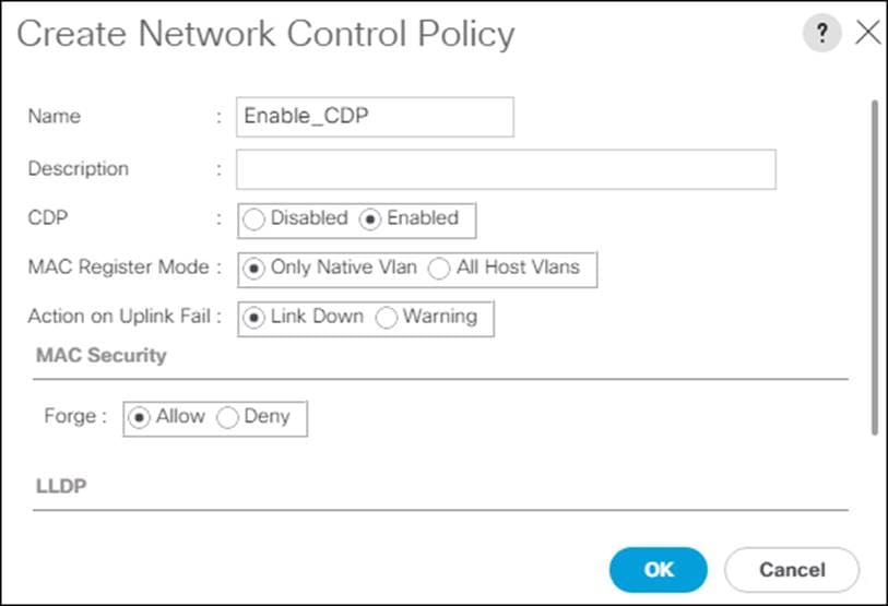
8. Click OK.
Configure Cisco UCS LAN Connectivity
To configure the necessary port channels out of the Cisco UCS environment, follow these steps:
1. In Cisco UCS Manager, click the LAN tab in the navigation pane.
![]() In this procedure, two port channels are created: one from fabric A to both Cisco Nexus switches and one from fabric B to both Cisco Nexus switches.
In this procedure, two port channels are created: one from fabric A to both Cisco Nexus switches and one from fabric B to both Cisco Nexus switches.
2. Under LAN > LAN Cloud, expand the Fabric A tree.
3. Right-click Port Channels.
4. Click Create Port Channel.
5. Enter a unique ID for the port channel, (149 in our example to correspond with the upstream Nexus port channel).
6. With 149 selected, enter PC-149-Nexus for the name of the port channel.
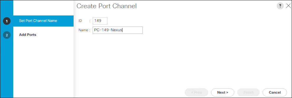
7. Click Next.
8. Choose the following ports to be added to the port channel:
a. Slot ID 1 and port 49
b. Slot ID 1 and port 50
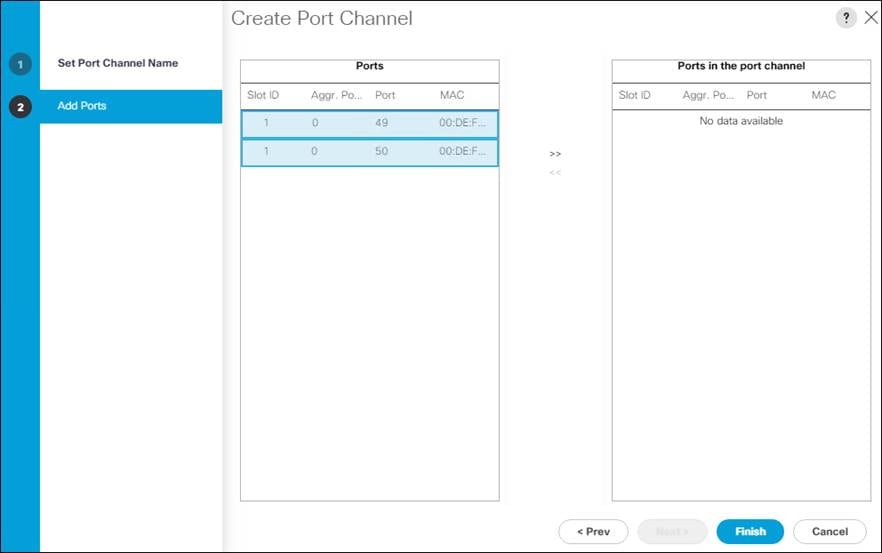
9. Click >> to add the ports to the port channel.
10. Click Finish to create the port channel.
11. Click OK.
12. In the navigation pane, under LAN > LAN Cloud, expand the fabric B tree.
13. Right-click Port Channels.
14. Click Create Port Channel.
15. Enter a unique ID for the port channel, (150 in our example to correspond with the upstream Nexus port channel).
16. With 150 selected, enter PC-150-Nexus for the name of the port channel.
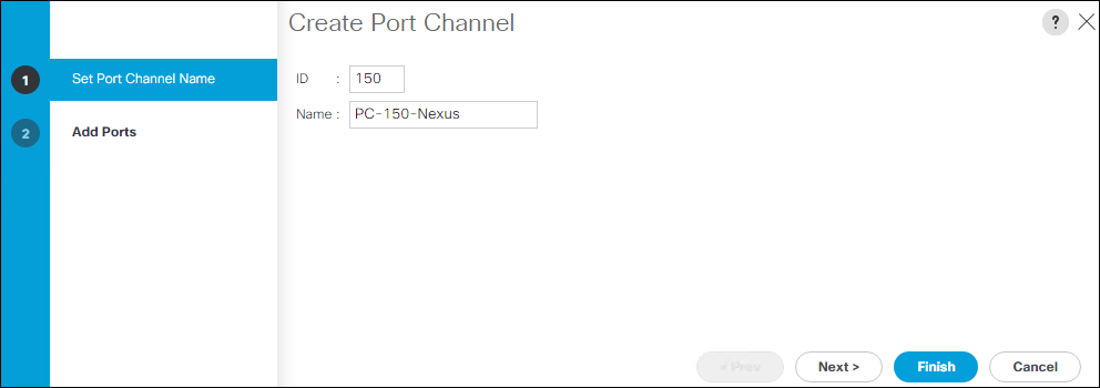
17. Click Next.
18. Choose the following ports to be added to the port channel:
a. Slot ID 1 and port 49
b. Slot ID 1 and port 50
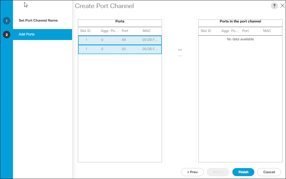
19. Click >> to add the ports to the port channel.
20. Click Finish to create the port channel.
21. Click OK.
To configure the necessary virtual local area networks (VLANs) for the Cisco UCS environment, follow these steps:
1. In Cisco UCS Manager, click the LAN tab in the navigation pane.
![]() In this procedure, six unique VLANs are created. See Table 2 for a list of VLANs to be created.
In this procedure, six unique VLANs are created. See Table 2 for a list of VLANs to be created.
2. Click LAN > LAN Cloud.
3. Right-click VLANs.
4. Click Create VLANs.
5. Enter Native-VLAN for the name of the VLAN to be used for the native VLAN.
6. Keep the Common/Global option selected for the scope of the VLAN.
7. Enter the native VLAN ID.
8. Keep the Sharing Type as None.
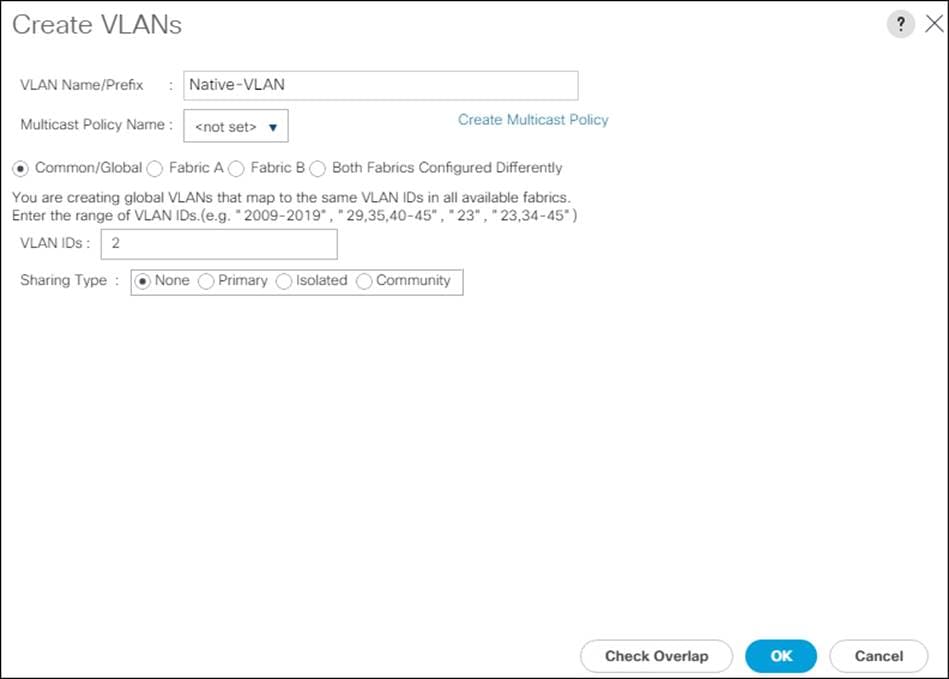
9. Click OK and then click OK again.
10. Expand the list of VLANs in the navigation pane, right-click the newly created Native-VLAN and click Set as Native VLAN.
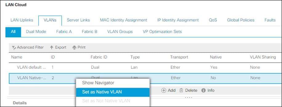
11. Click Yes, and then click OK.
12. Right-click VLANs.
13. Click Create VLANs
14. Enter IB-Mgmt for the name of the VLAN to be used for management traffic.
15. Keep the Common/Global option selected for the scope of the VLAN.
16. Enter the In-Band management VLAN ID.
17. Keep the Sharing Type as None.
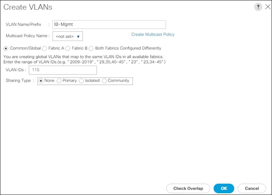
18. Click OK and then click OK again.
19. Right-click VLANs.
20. Click Create VLANs.
21. Enter vMotion for the name of the VLAN to be used for vMotion.
22. Keep the Common/Global option selected for the scope of the VLAN.
23. Enter the vMotion VLAN ID.
24. Keep the Sharing Type as None.
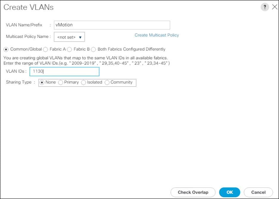
25. Click OK and then click OK again.
26. Right-click VLANs.
27. Click Create VLANs.
28. Enter VM-App- for the prefix of the VLANs to be used for VM Traffic.
29. Keep the Common/Global option selected for the scope of the VLAN.
30. Enter the VM-Traffic VLAN ID range.

31. Click OK and then click OK again.
32. Right-click VLANs.
33. Click Create VLANs.
34. Enter iSCSI-A-VLAN for the name of the VLAN to be used for iSCSI-A.
35. Choose Fabric A for the scope of the VLAN.
36. Enter the iSCSI-A VLAN ID.
37. Keep the Sharing Type as None.
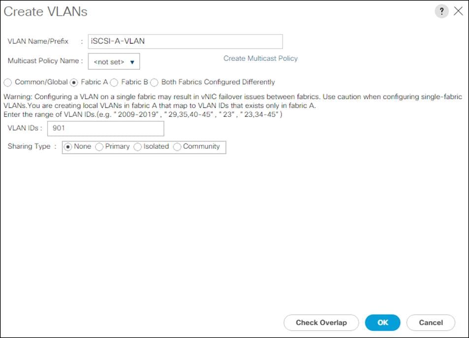
38. Click OK and then click OK again
39. Right-click VLANs.
40. Click Create VLANs.
41. Enter iSCSI-B-VLAN for the name of the VLAN to be used for iSCSI-B.
42. Choose Fabric B for the scope of the VLAN.
43. Enter the iSCSI-B VLAN ID.
44. Keep the Sharing Type as None.

45. Click OK and then click OK again
To create the multiple virtual network interface card (vNIC) templates for the Cisco UCS environment, follow the steps in the following sections.
Create Management vNICs
For the vNIC_Mgmt_A Template, follow these steps:
1. In Cisco UCS Manager, click the LAN tab in the navigation pane.
2. Click Policies > root.
3. Right-click vNIC Templates.
4. Click Create vNIC Template.
5. Enter vNIC_Mgmt_A for the vNIC template name.
6. Keep Fabric A selected.
7. Choose Primary Template for the Redundancy Type.
8. Leave Peer Redundancy Template as <not set>
![]() Redundancy Type and specification of Redundancy Template are configuration options to later allow changes to the Primary Template to automatically adjust onto the Secondary Template.
Redundancy Type and specification of Redundancy Template are configuration options to later allow changes to the Primary Template to automatically adjust onto the Secondary Template.
9. Under Target, make sure that the VM checkbox is not selected.
10. Choose Updating Template for the Template Type.
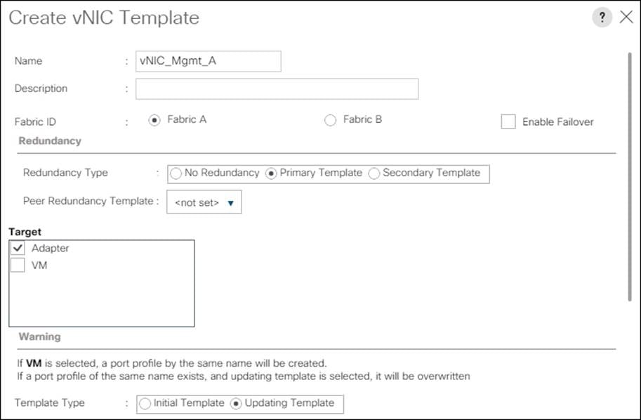
11. Under VLANs, check the boxes for IB-Mgmt and Native-VLAN VLANs.
12. Set Native-VLAN for the native VLAN.
13. Leave vNIC Name selected for the CDN Source.
14. Leave 1500 for the MTU.
15. In the MAC Pool list, Click MAC_Pool_A.
16. In the Network Control Policy list, Click Enable_CDP.
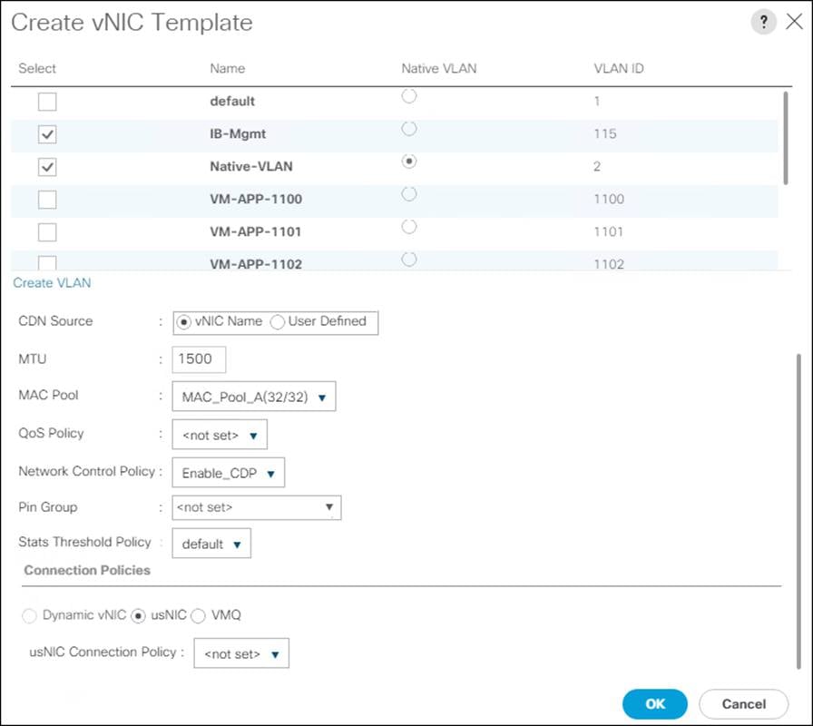
17. Click OK to create the vNIC template.
18. Click OK.
For the vNIC_Mgmt_B Template, follow these steps:
1. In the navigation pane, Click the LAN tab.
2. Click Policies > root.
3. Right-click vNIC Templates.
4. Click Create vNIC Template
5. Enter vNIC_Mgmt_B for the vNIC template name.
6. Click Fabric B.
7. Choose Secondary Template for Redundancy Type.
8. From the Peer Redundancy Template drop-down list, click vNIC_Mgmt_A.
![]() With Peer Redundancy Template selected, Failover specification, Template Type, VLANs, CDN Source, MTU, and Network Control Policy are all pulled from the Primary Template.
With Peer Redundancy Template selected, Failover specification, Template Type, VLANs, CDN Source, MTU, and Network Control Policy are all pulled from the Primary Template.
9. Under Target, make sure the VM checkbox is not selected.
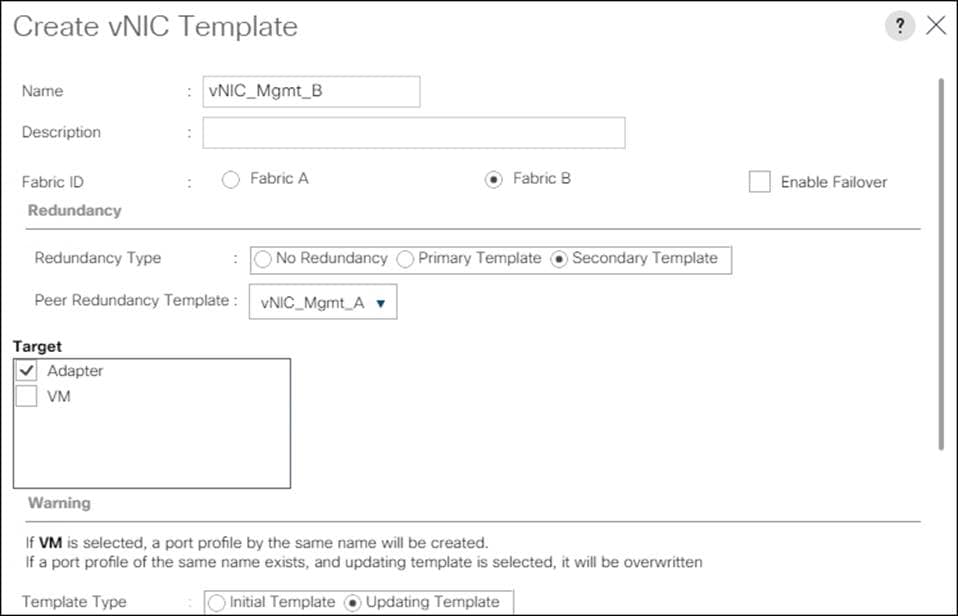
10. In the MAC Pool list, click MAC_Pool_B.
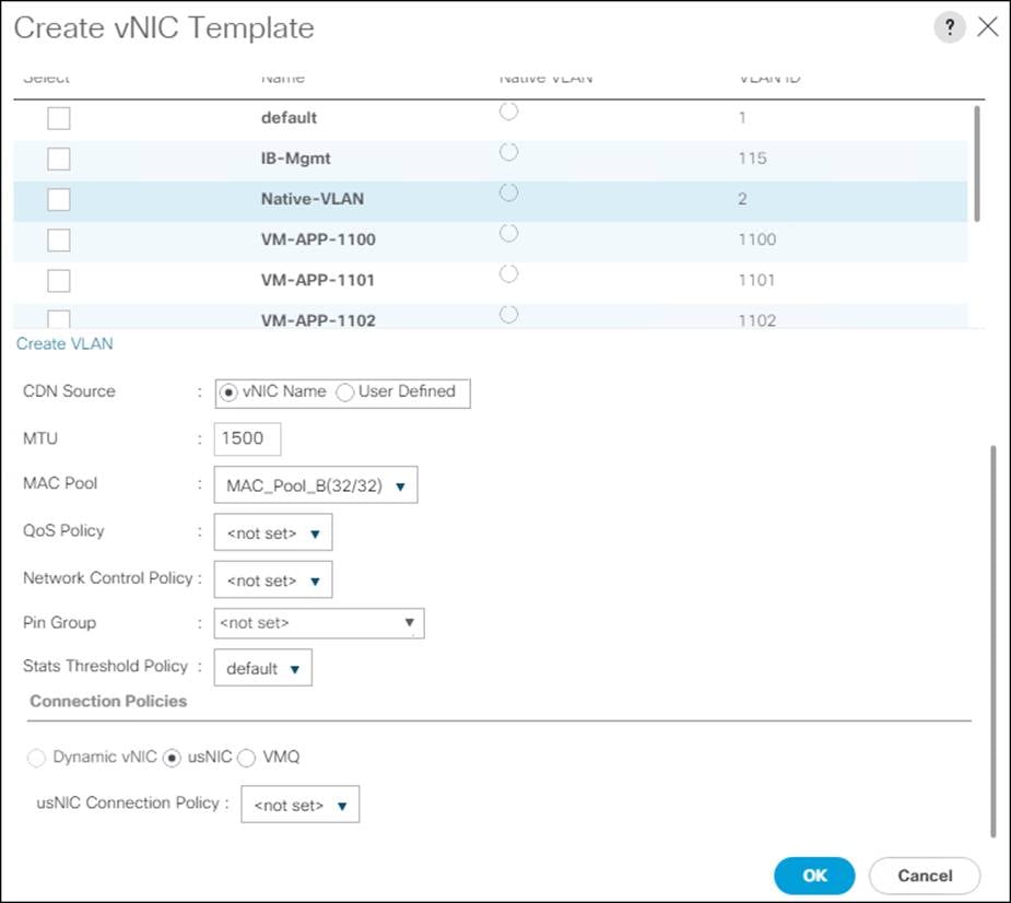
11. Click OK to create the vNIC template.
12. Click OK.
Create iSCSI vNICs
For the vNIC_iSCSI_A Template, follow these steps:
1. In Cisco UCS Manager, click the LAN tab in the navigation pane.
2. Click Policies > root.
3. Right-click vNIC Templates.
4. Click Create vNIC Template.
5. Enter vNIC_iSCSI_A for the vNIC template name.
6. Keep Fabric A selected.
7. Leave Redundancy Type as No Redundancy.
8. Leave Peer Redundancy Template as <not set>
9. Under Target, make sure that the VM checkbox is not selected.
10. Choose Updating Template for the Template Type.

11. Under VLANs, check the boxes for iSCSI-A-VLAN and set it to Native VLAN.
12. Set Native-VLAN for the native VLAN.
13. Leave vNIC Name selected for the CDN Source.
14. Set MTU to 9000.
15. In the MAC Pool list, click MAC_Pool_A.
16. In the Network Control Policy list, click Enable_CDP.
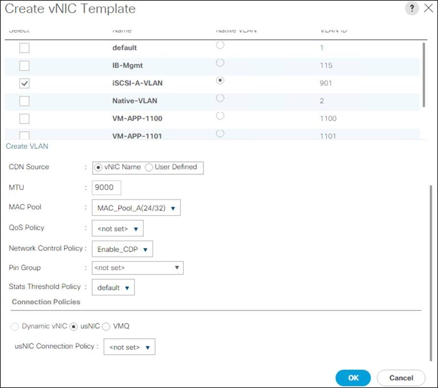
17. Click OK to create the vNIC template.
18. Click OK.
For the vNIC_iSCSI_B Template, follow these steps:
1. In the navigation pane, click the LAN tab.
2. Click Policies > root.
3. Right-click vNIC Templates.
4. Click Create vNIC Template.
5. Enter vNIC_iSCSI_B for the vNIC template name.
6. Click Fabric B.
7. Leave Redundancy Type as No Redundancy.
8. Leave Peer Redundancy Template as <not set>
9. Under Target, make sure the VM checkbox is not selected.
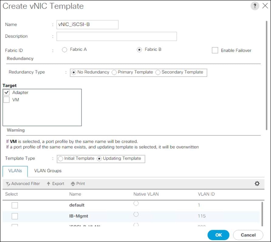
10. Under VLANs, check the boxes for iSCSI-B-VLAN and set it to Native VLAN.
11. Set Native-VLAN for the native VLAN.
12. Leave vNIC Name selected for the CDN Source.
13. Set MTU to 9000.
14. In the MAC Pool list, click MAC_Pool_B.
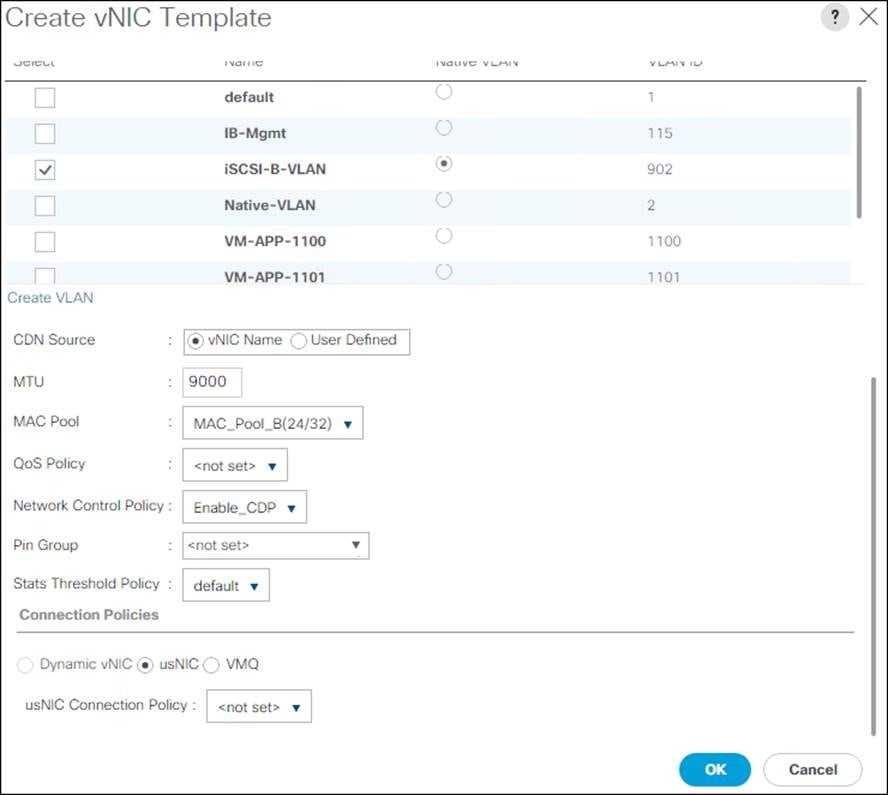
15. Click OK to create the vNIC template.
16. Click OK.
Create Data vNICs
For the vNIC_Data_A Template, follow these steps:
1. In Cisco UCS Manager, click the LAN tab in the navigation pane.
2. Click Policies > root.
3. Right-click vNIC Templates.
4. Click Create vNIC Template.
5. Enter vNIC_Data_A for the vNIC template name.
6. Keep Fabric A selected.
7. Choose Primary Template for the Redundancy Type.
8. Leave Peer Redundancy Template as <not set>
9. Under Target, make sure that the VM checkbox is not selected.
10. Choose Updating Template for the Template Type.
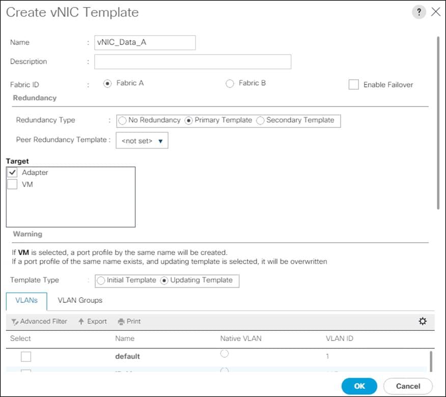
11. Under VLANs, check the boxes for vMotion, Apps, and Native-VLAN.
12. Set Native-VLAN for the native VLAN.
13. For MTU, enter 9000.
14. In the MAC Pool list, choose MAC_Pool_A.
15. In the Network Control Policy list, choose Enable_CDP.
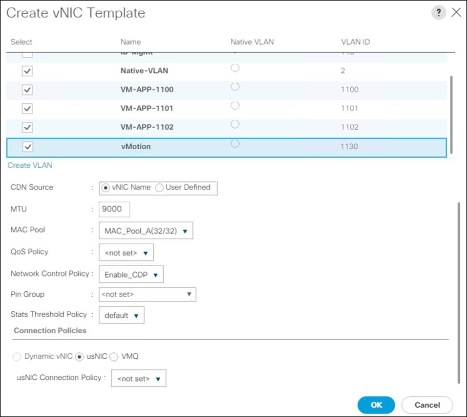
16. Click OK to create the vNIC template.
17. Click OK.
For the vNIC_Data_B Template, follow these steps:
1. In the navigation pane, click the LAN tab.
2. Click Policies > root.
3. Right-click vNIC Templates.
4. Click Create vNIC Template.
5. Enter vNIC_Data_B for the vNIC template name.
6. Click Fabric B.
7. Choose Secondary Template for Redundancy Type.
8. From the Peer Redundancy Template drop-down list, click vNIC_Data_A.
![]() With Peer Redundancy Template selected, MAC Pool will be the main configuration option left for this vNIC template.
With Peer Redundancy Template selected, MAC Pool will be the main configuration option left for this vNIC template.
9. Under Target, make sure the VM checkbox is not selected.
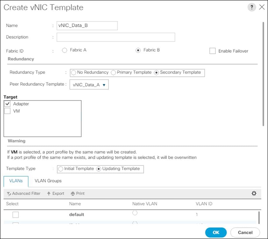
10. In the MAC Pool list, choose MAC_Pool_B.
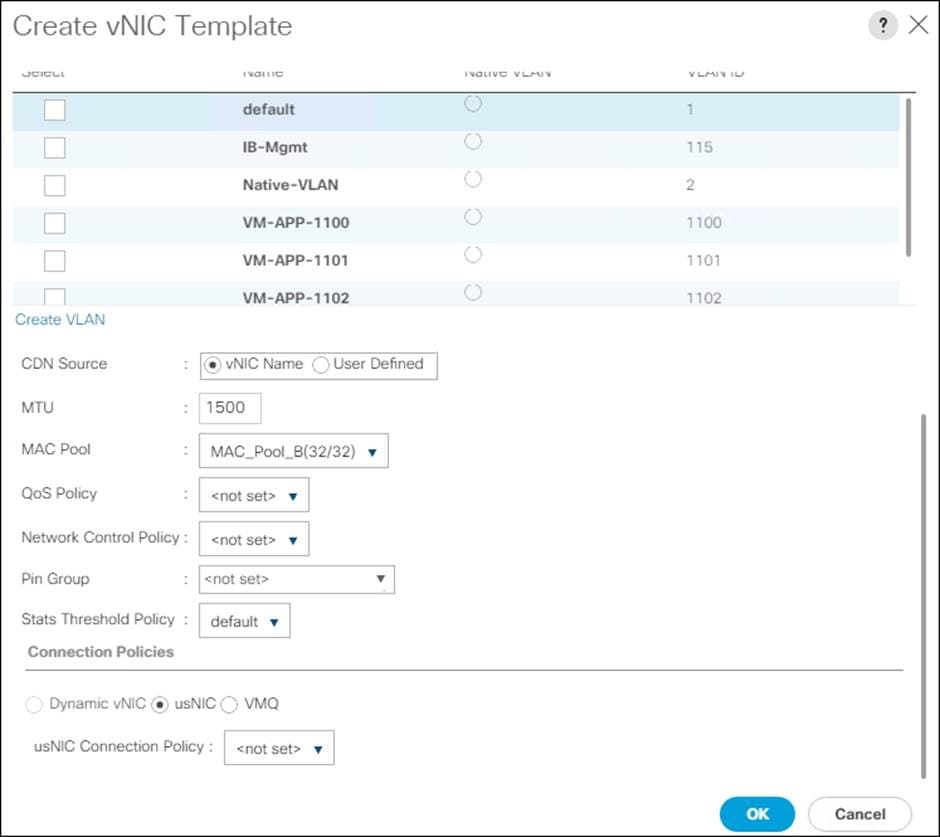
11. Click OK to create the vNIC template.
12. Click OK.
Create LAN Connectivity Policy
To configure the necessary iSCSI Infrastructure LAN Connectivity Policy, follow these steps:
1. In Cisco UCS Manager, click LAN.
2. Click LAN > Policies > root.
3. Right-click LAN Connectivity Policies.
4. Click Create LAN Connectivity Policy.
5. Enter iSCSI-LAN-Policy for the name of the policy.
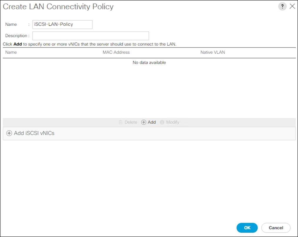
6. Click the upper Add button to add a vNIC.
7. In the Create vNIC dialog box, enter 00-Mgmt-A for the name of the vNIC.
![]() The numeric prefix of “00-“ and subsequent increments on the later vNICs are used in the vNIC naming to force the device ordering through Consistent Device Naming (CDN). Without this, some operating systems might not respect the device ordering that is set within Cisco UCS.
The numeric prefix of “00-“ and subsequent increments on the later vNICs are used in the vNIC naming to force the device ordering through Consistent Device Naming (CDN). Without this, some operating systems might not respect the device ordering that is set within Cisco UCS.
8. Check to box for the Use vNIC Template..
9. In the vNIC Template list, choose 00-Mgmt-A.
10. In the Adapter Policy list, choose VMWare.
11. Click OK to add this vNIC to the policy.
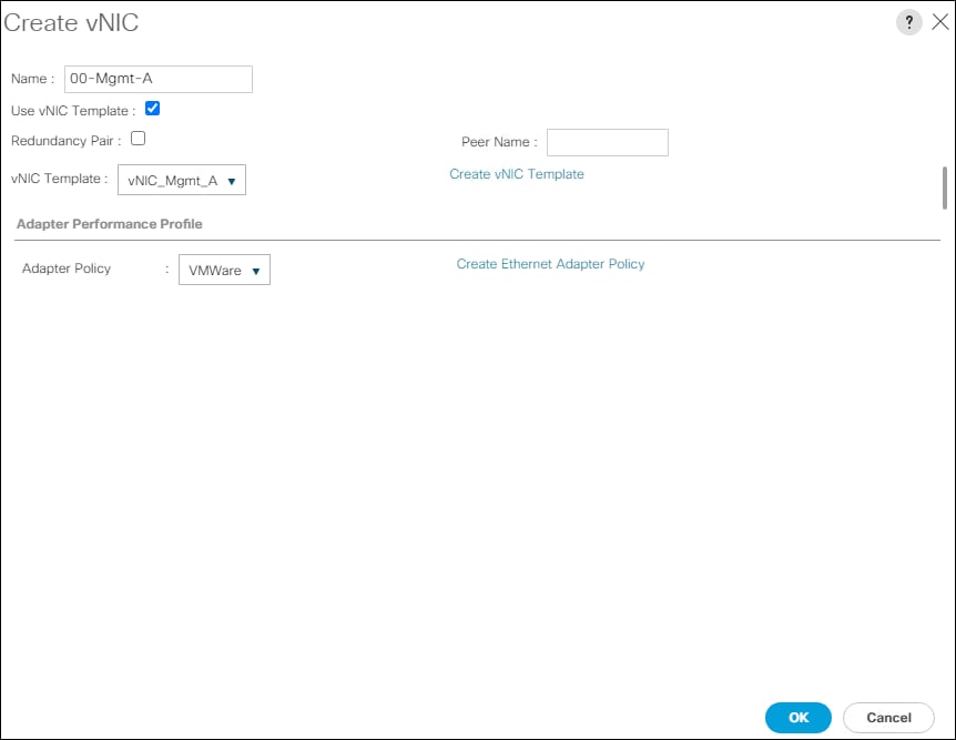
12. Click the upper Add button to add another vNIC to the policy.
13. In the Create vNIC box, enter 01-Mgmt-B for the name of the vNIC.
14. Check the box for the Use vNIC Template.
15. In the vNIC Template list, choose 01-Mgmt-B.
16. In the Adapter Policy list, choose VMWare.
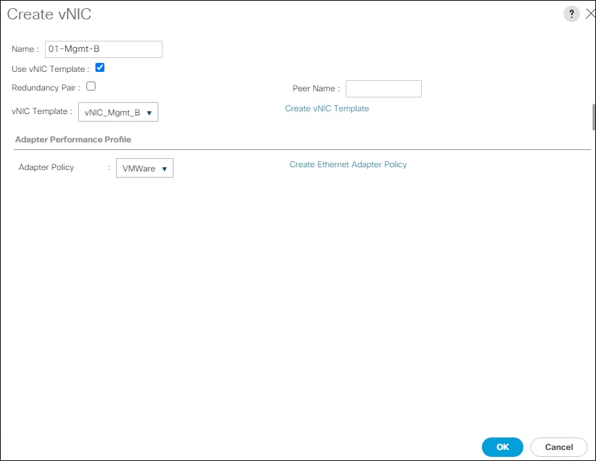
17. Click OK to add the vNIC to the policy.
18. Click the upper Add button to add a vNIC.
19. In the Create vNIC dialog box, enter 02-Data-A for the name of the vNIC.
20. Check the box for the Use vNIC Template.
21. In the vNIC Template list, choose vNIC_Data_A.
22. In the Adapter Policy list, choose VMWare.
23. Click OK to add this vNIC to the policy.
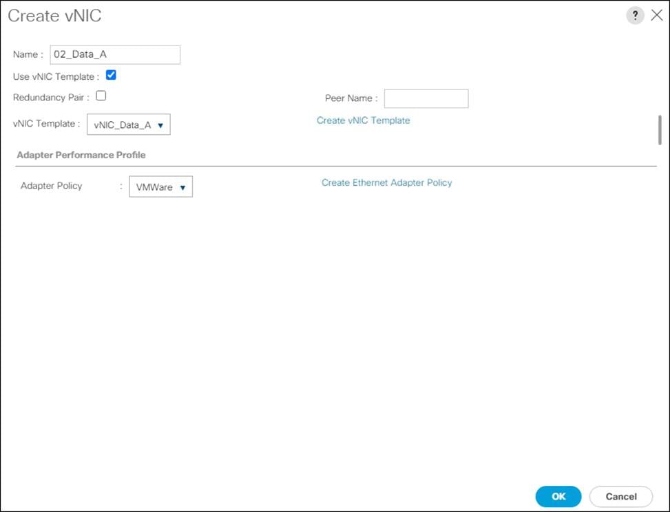
24. Click the upper Add button to add a vNIC to the policy.
25. In the Create vNIC dialog box, enter 03-Data-B for the name of the vNIC.
26. Check the box for the Use vNIC Template.
27. In the vNIC Template list, choose vNIC_Data_B.
28. In the Adapter Policy list, choose VMWare.

29. Click OK to add this vNIC to the policy.
30. Click the upper Add button to add a vNIC to the policy.
31. In the Create vNIC dialog box, enter 04-iSCSI-A for the name of the vNIC.
32. Check the box for the Use vNIC Template.
33. In the vNIC Template list, choose vNIC_iSCSI-A.
34. In the Adapter Policy list, choose VMWare.
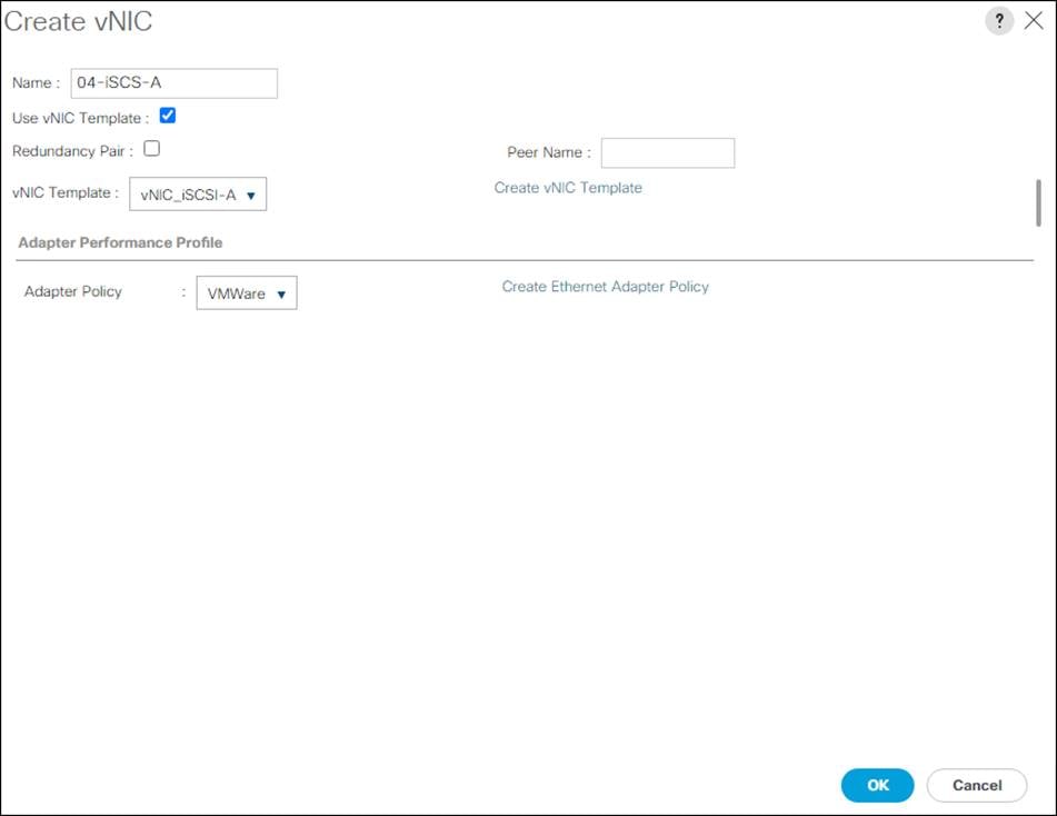
35. Click OK to add this vNIC to the policy.
36. Click the upper Add button to add a vNIC to the policy.
37. In the Create vNIC dialog box, enter 05-iSCSI-B for the name of the vNIC.
38. Check the box for the Use vNIC Template.
39. In the vNIC Template list, choose vNIC_iSCSI-B.
40. In the Adapter Policy list, choose VMWare.
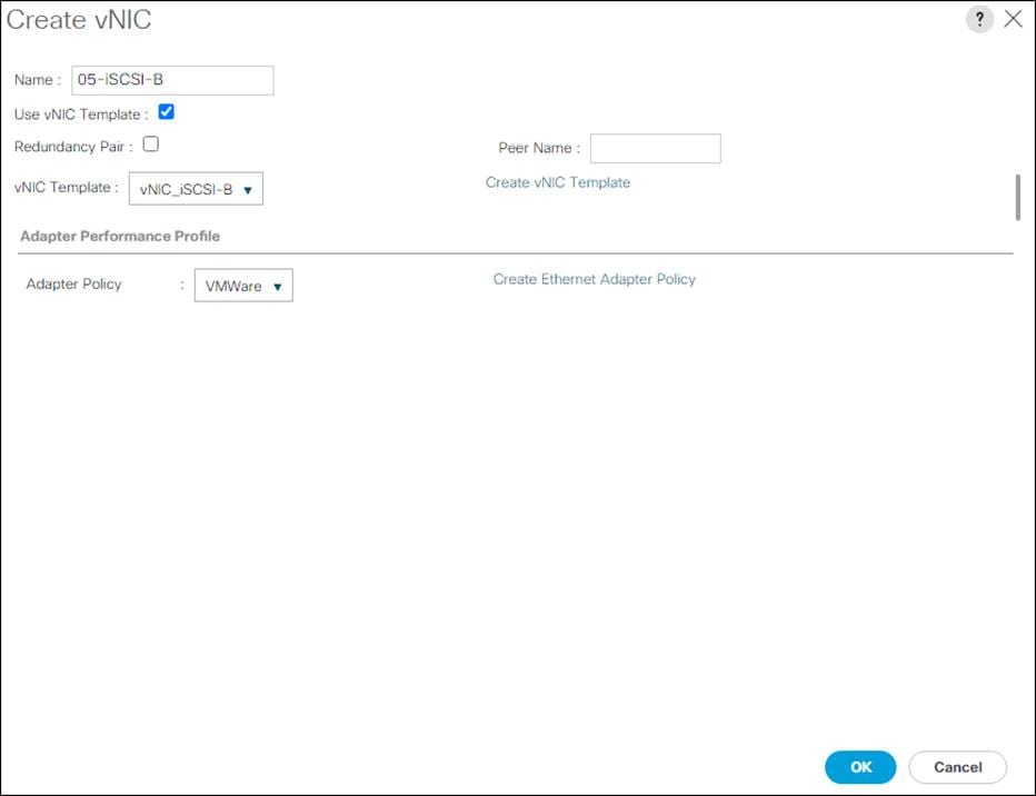
41. Click OK to add this vNIC to the policy.
42. Expand the Add iSCSI vNICs Section
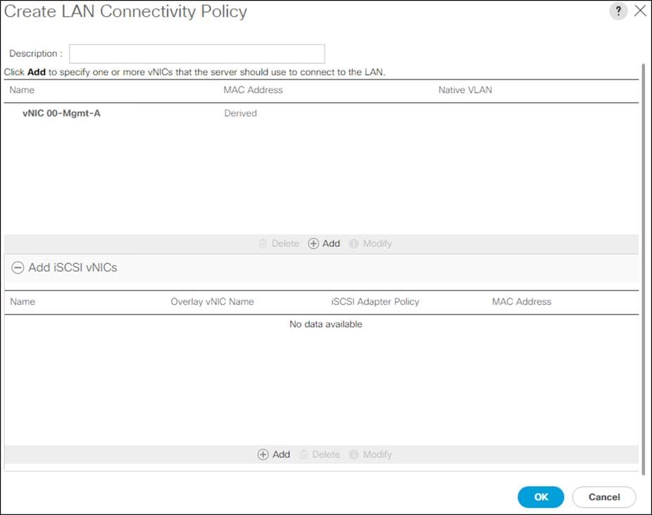
43. Click Add in Add iSCSI vNICs section.
44. Set the name to iSCSI-A-vNIC.
45. Choose 04-iSCSI-A for the Overlay vNIC.
46. Set VLAN to iSCSI-A-VLAN (native).
47. Set the iSCSI Adapter Policy to default.
48. Leave the MAC Address set to None.
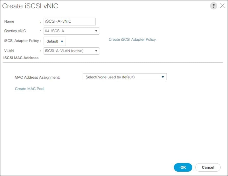
49. Click OK.
50. Click Add in Add iSCSI vNICs section.
51. Set the name to iSCSI-B-vNIC.
52. Choose 05-iSCSI-B for the Overlay vNIC.
53. Set VLAN to iSCSI-B-VLAN (native).
54. Set the iSCSI Adapter Policy to default.
55. Leave the MAC Address set to None.
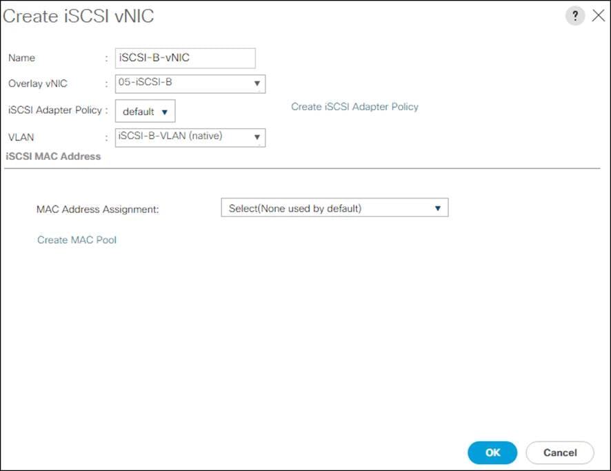
56. Click OK.
57. Click OK again to create the LAN Connectivity Policy.
This procedure will define the Primary and Secondary Boot Targets for each Fabric side (A/B). These will be the iSCSI interfaces that were previously configured on the Pure Storage FlashArray//X50 R3.
To create boot policies for the Cisco UCS environment, follow these steps:
1. In Cisco UCS Manager, click the Servers tab in the navigation pane.
2. Click Policies > root.
3. Right-click Boot Policies.
4. Click Create Boot Policy.
5. Enter Boot-iSCSI-A for the name of the boot policy.
6. Optional: Enter a description for the boot policy.
7. Set boot Mode to Uefi.
![]() Do not check the box for Reboot on Boot Order Change.
Do not check the box for Reboot on Boot Order Change.
8. Expand the Local Devices drop-down list and choose Add Remote CD/DVD.
9. Expand the iSCSI vNICs drop-down list and choose add iSCSI Boot.
10. Enter iSCSI-A-vNIC for the iSCSI vNIC.
11. Click OK.
12. Click Add iSCSI boot.
13. Enter iSCSI-B-vNIC for the iSCSI vNIC.
14. Click OK.
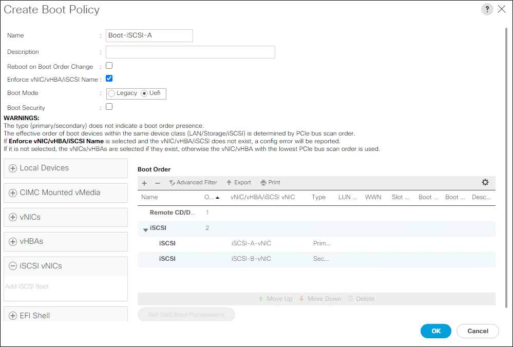
15. Click OK, then click OK again to create the boot policy.
Create Service Profile Templates
In this procedure, one service profile template for Infrastructure ESXi hosts is created for FC boot.
To create the service profile template, follow these steps:
1. In Cisco UCS Manager, click the Servers tab in the navigation pane.
2. Click Service Profile Templates > root.
3. Right-click root.
4. Click Create Service Profile Template to open the Create Service Profile Template wizard.
5. Enter VM-AMD-Host-iSCSI-A for the name of the service profile template. This service profile template is configured to boot from FlashArray//X50 R3 controller 1 on fabric A.
6. Choose the “Updating Template” option.
7. Under UUID, choose UUID_Pool for the UUID pool.
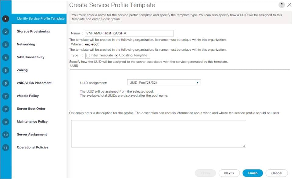
8. Click Next.
Configure Storage Provisioning
To configure the storage provisioning, follow these steps:
1. Click Local Disk Configuration Policy tab.
2. If you have servers with no physical disks, click the Local Disk Configuration Policy tab and choose the SAN-Boot Local Storage Policy. Otherwise, choose the default Local Storage Policy.
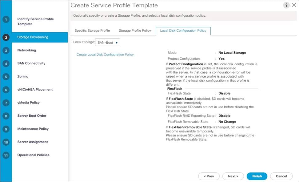
3. Click Next.
Configure Networking Options
To configure the network options, follow these steps:
1. Keep the default setting for Dynamic vNIC Connection Policy.
2. Choose the “Use Connectivity Policy” option to configure the LAN connectivity.
3. Choose iSCSI-LAN-Policy from the LAN Connectivity Policy drop-down list.
4. Choose IQN_Pool for the Initiator Name Assignment.
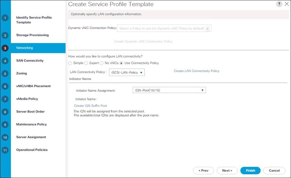
5. Click Next.
Configure SAN Connectivity Options
1. Click the No vHBAs.
2. Click Next.
Configure Zoning Options
1. Leave Zoning configuration unspecified and click Next.
Configure vNIC/HBA Placement
1. In the “Select Placement” list, leave the placement policy as “Let System Perform Placement”.
2. Click Next.
Configure vMedia Policy
1. Do not select a vMedia Policy.
2. Click Next.
Configure Server Boot Order
1. Choose Boot-iSCSI-A for Boot Policy.
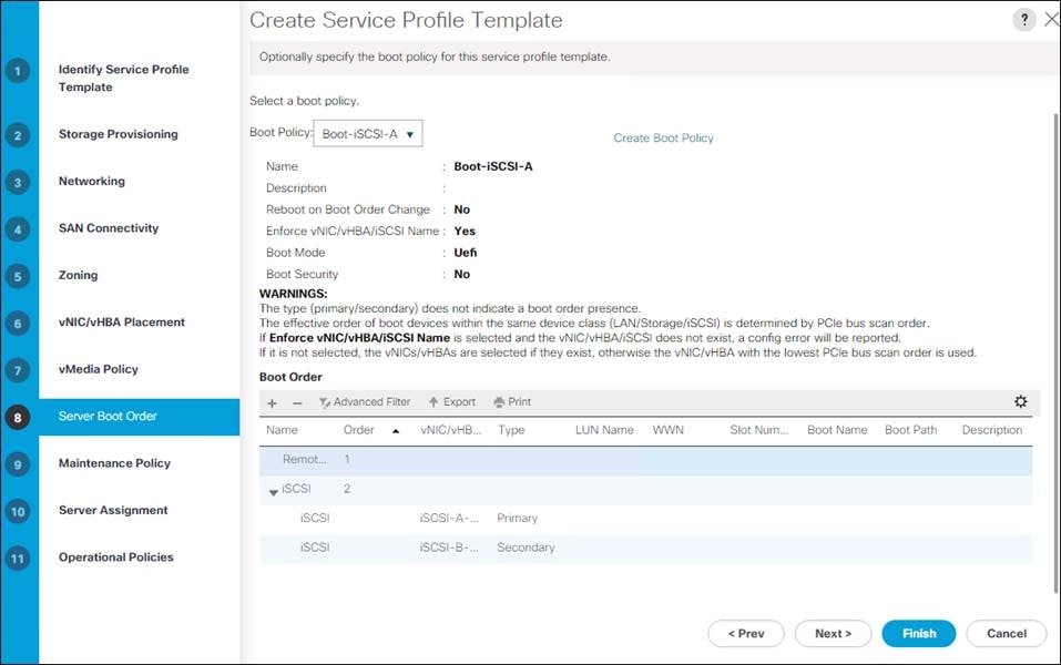
2. In the Boot order, click iSCSI-A-vNIC.
3. Click Set iSCSI Boot Parameters.
4. Leave Authentication Profile at <not set>.
5. Leave Initiator Name Assignment at <not set>.
6. Set Initiator IP address Policy to iSCSI_IP_Pool_A.
7. Choose iSCSI Static Target Interface option.
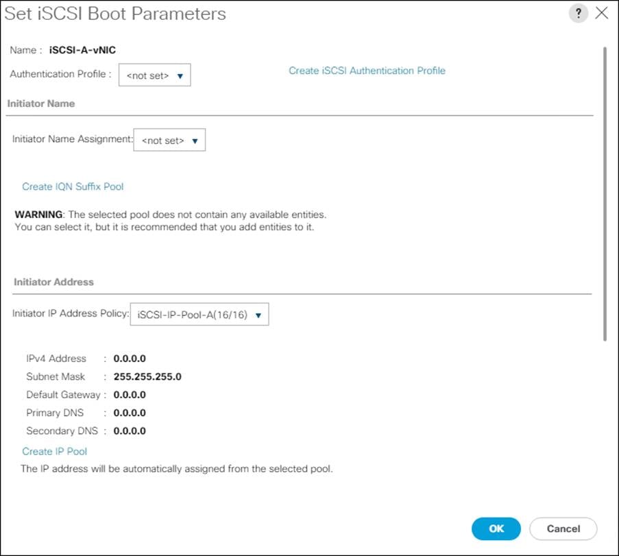
8. Scroll down and click Add.
9. Enter the iSCSI Target Name for CT0.eth4. To get the iSCSI target name from the FlashArray//X50 R3, login to the Pure Web Console and navigate to Health -> Connections -> Array Ports.
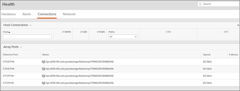
10. Leave the Port set to 3260.
11. Leave Authentication Profile as <not set>.
12. Enter the CT0.eth4 IPv4 Address.
13. Set the LUN ID to 1.
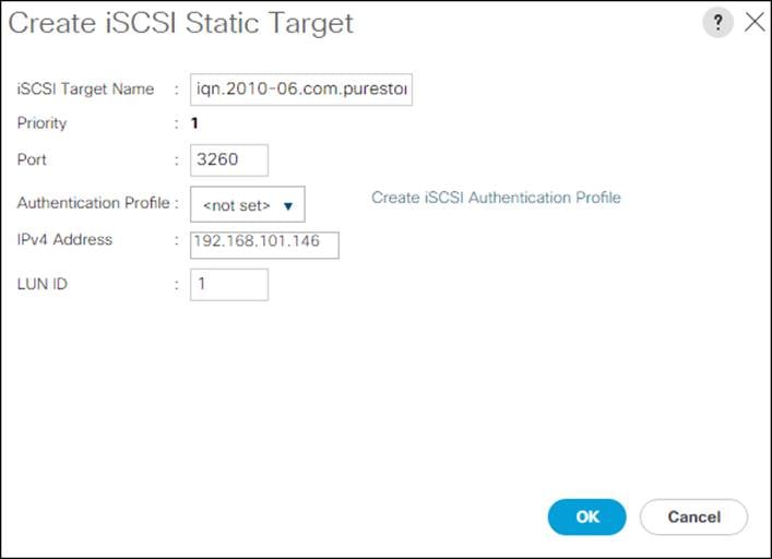
14. Click OK.
15. Click Add again to add another iSCSI Target for iSCSI-A-vNIC for CT1.eth4.
16. Enter the same iSCSI target name.
17. Leave the Port as 3260.
18. Leave Authentication Profile as <not set>.
19. Enter the CT1.eth4 IPv4 Address.
20. Set the LUN ID to 1.
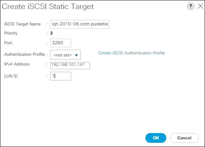
21. Click OK.
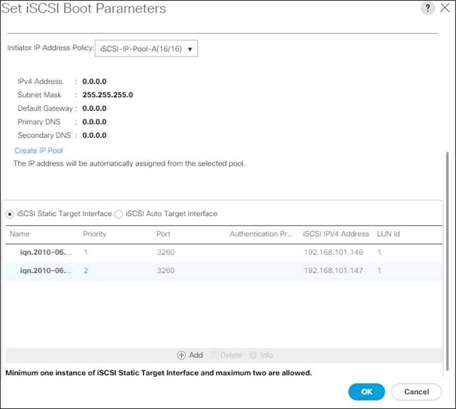
22. Click OK.
23. In the Boot order, click iSCSI-A-vNIC.
24. Click Set iSCSI Boot Parameters.
25. Leave Authentication Profile at <not set>.
26. Leave Initiator Name Assignment at <not set>.
27. Set Initiator IP address Policy to iSCSI_IP_Pool_A.
28. Choose iSCSI Static Target Interface option.
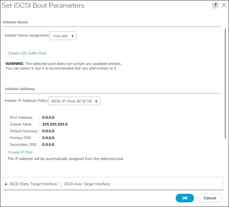
29. Click Add.
30. Enter the same iSCSI target name.
31. Leave the Port as 3260.
32. Leave Authentication Profile as <not set>.
33. Enter the CT0.eth5 IPv4 Address.
34. Set the LUN ID to 1.
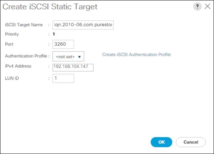
35. Click OK.
36. Click Add.
37. Enter the same iSCSI target name.
38. Leave the Port as 3260.
39. Leave Authentication Profile as <not set>.
40. Enter the CT1.eth5 IPv4 Address.
41. Set the LUN ID to 1.
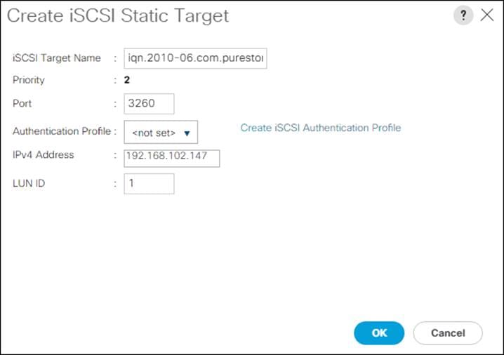
42. Click OK.
43. Click OK.
44. Click Next to continue to the next section.
Configure Maintenance Policy
1. Change the Maintenance Policy to default.
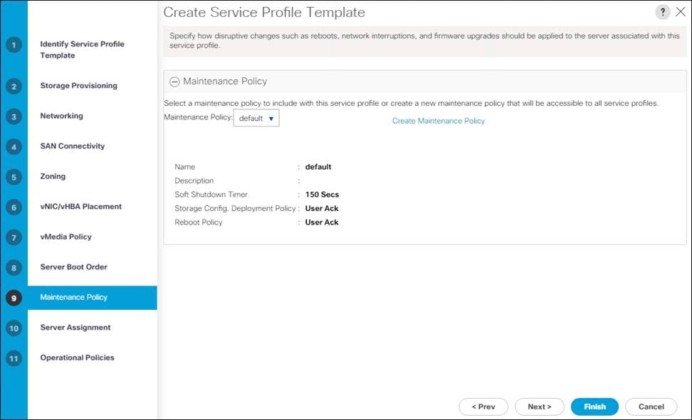
2. Click Next.
Configure Server Assignment
To configure server assignment, follow these steps:
1. In the Pool Assignment list, choose AMD_Pool.
2. Optional: Select a Server Pool Qualification policy.
3. Choose Down for the power state to be applied when the profile is associated with the server.
4. Optional: Choose “UCS-C125-M5” for the Server Pool Qualification.
5. Firmware Management at the bottom of the page can be left alone as it will use default from the Host Firmware list.
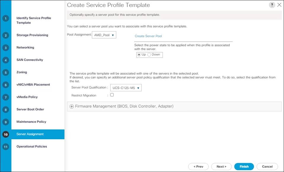
6. Click Next.
Configure Operational Policies
To configure the operational policies, follow these steps:
1. In the BIOS Policy list, choose AMD-VM-Host.
2. Expand Power Control Policy Configuration and choose No-Power-Cap in the Power Control Policy list.
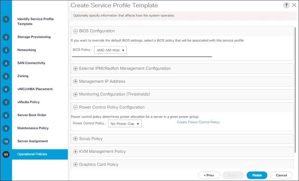
3. Click Finish to create the service profile template.
4. Click OK in the confirmation message.
To create service profiles from the service profile template, follow these steps:
1. Connect to the UCS 6454 Fabric Interconnect UCS Manager, click the Servers tab in the navigation pane.
2. Click Service Profile Templates > root > Service Template VM-Host-iSCSI-A.
3. Right-click VM-AMD-Host-iSCSI-A and choose Create Service Profiles from Template.
4. Enter VM-AMD-Host-iSCSI- for the service profile prefix.
5. Leave 1 as “Name Suffix Starting Number.”
6. Leave 2 for the “Number of Instances.”
7. Click OK to create the service profiles.
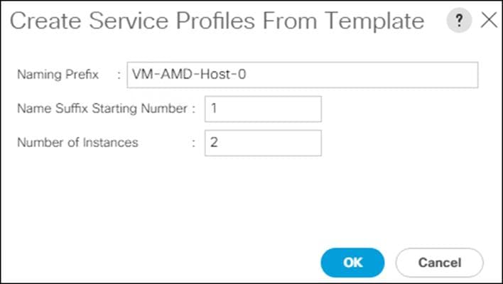
8. Click OK in the confirmation message to provision two FlashStack Service Profiles.
Claim UCS Domain in Intersight
1. Connect to the UCS 6454 Fabric Interconnect UCS Manager, click the Admin tab in the navigation pane.
2. Click Device Connector.
3. Set Intersight Management to Enabled.
4. Copy the Device ID and Claim Code.
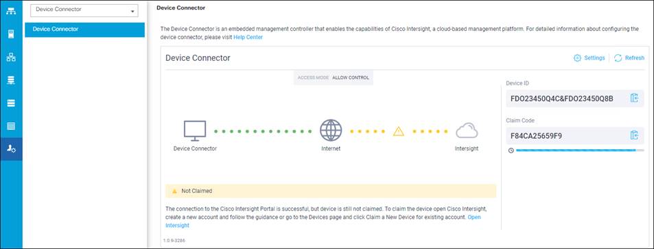
5. Open a browser to Cisco Intersight, https://intersight.com and log in to your Intersight account.
6. Click Admin > Devices.
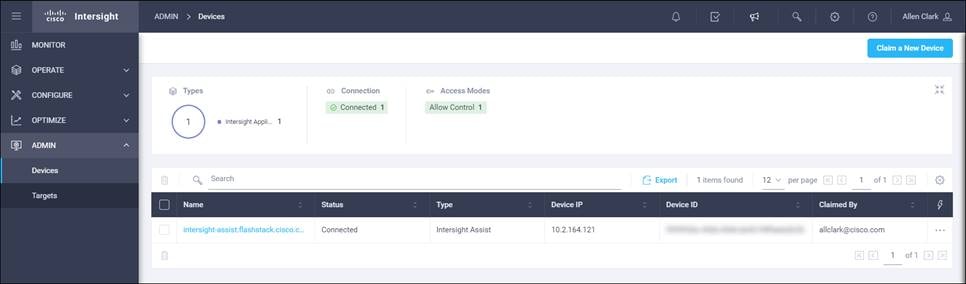
7. Click Claim a New Device and enter your Device ID and Claim Code under the Direct Claim option.
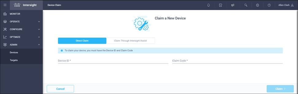
8. Click Claim.
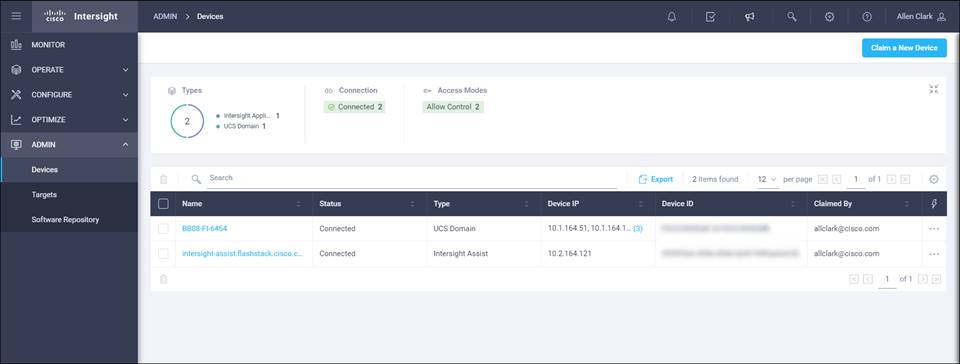
The Pure Storage FlashArray//X is accessible to the FlashStack, but no storage has been deployed at this point. The storage to be deployed will include:
● ESXi iSCSI Boot LUNs
● VMFS Datastores
● vVol Data Stores
The iSCSI Boot LUNs will need to be setup from the Pure Storage Web Portal, and the VMFS datastores will be directly provisioned from the vSphere Web Client after the Pure Storage vSphere Web Client Plugin has later been registered with the vCenter.
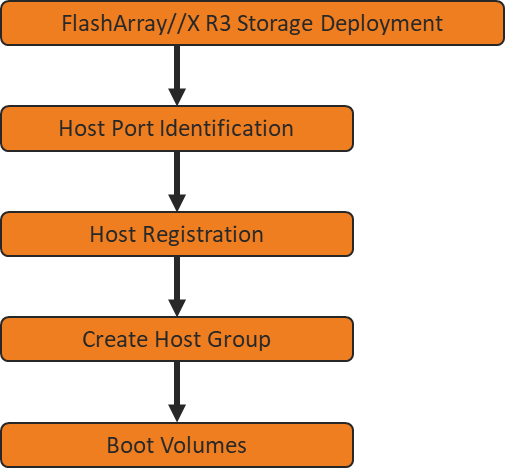
iSCSI Boot LUNs will be mapped by the FlashArray//X using the assigned Initiator IQN to the provisioned service profiles. This information can be found within the service profile located within the iSCSI vNIC tab.
To register a host, follow these steps. Intersight will be used to create a host.
1. Selection Configure -> Orchestration.
2. Click New Storage Host.

3. Click Execute.
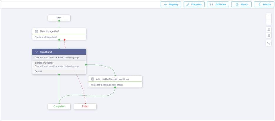
4. Choose the appropriate Organization (default by default).
5. Choose the appropriate Pure Storage device.
6. Enter the name of the Host name and IQN for host VM-AMD-Host-iSCSI-01.
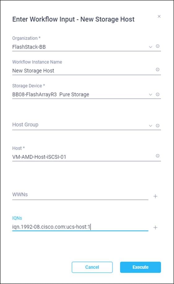
7. Click Execute.
8. Repeat steps 2-7 for all host.
To create a host group, follow these steps. Intersight will be used to create a host group
1. Selection Configure -> Orchestration.
2. Click New Storage Host Group.
3. Click Execute.
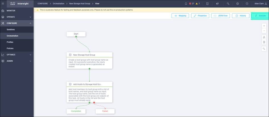
4. Choose the appropriate Organization.
5. Choose the appropriate Pure Storage device.
6. Enter the name of the Host Group and of the Hosts created during Host Registration. VM-AMD-Host-iSCSI-01 and VM-AMD-Host-iSCSI-02 are the host used in this deployment.
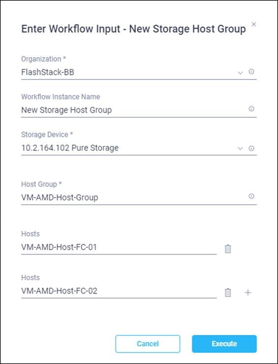
7. Click Execute.
Private Boot Volumes for each ESXi Host
To create private boot volumes for each ESXi Host, follow these steps in the Pure Storage Web Portal:
1. Click Storage > Volumes.
2. Click the + icon in the Volumes Panel.
3. A pop-up will appear to create a volume on the FlashArray.
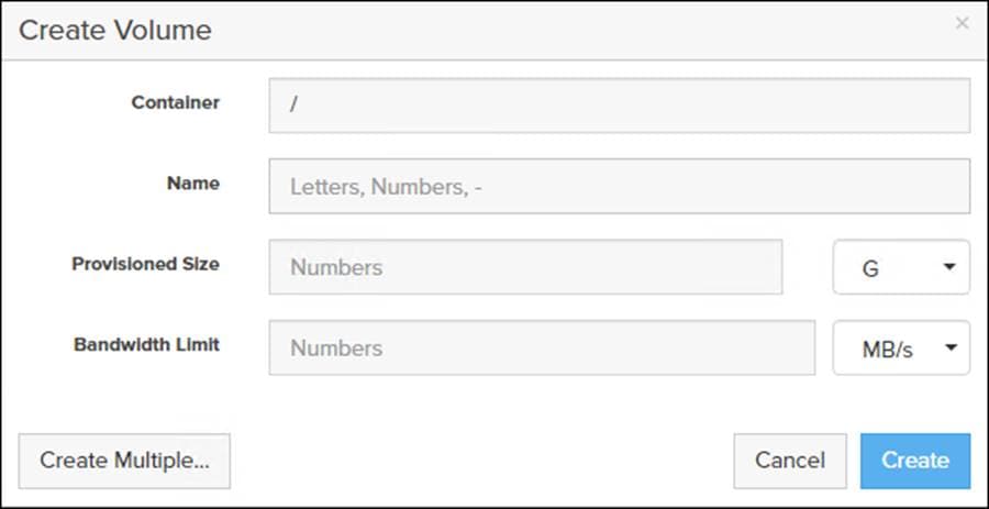
4. To create more than one volume, click the Create Multiple… option, filling in the Name, Provisioned Size, Staring Number, Count, and Number of Digits, with a “#” appearing in the name where an iterating number will appear.
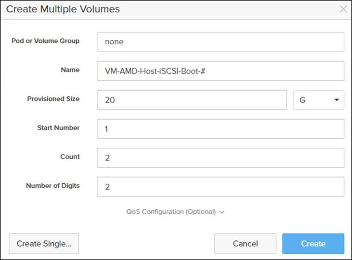
5. Click Create to provision the volumes to be used as iSCSI boot LUNs.
6. Go back to the Hosts section under the Storage tab. Click one of the hosts and click the gear icon drop-down within the Connected Volumes tab within that host.
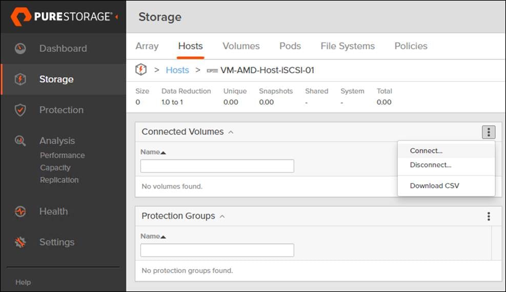
7. From the drop-down list of the gear icon, choose Connect Volumes, and a pop-up will appear.
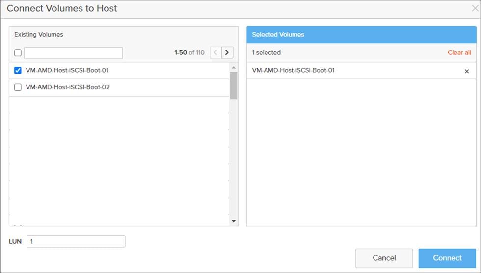
![]() LUN ID 1 should be used for the boot.
LUN ID 1 should be used for the boot.
8. Choose the volume that has been provisioned for the host, set the LUN ID for the volume, click the + next to the volume, and click Confirm to proceed. Repeat steps 1-7 for connecting volumes for each of the host/volume pairs configured.
This section provides detailed instructions to install VMware ESXi 7.0 in a FlashStack environment. After the procedures are completed, the FC SAN booted ESXi hosts will be configured.
Figure 5. ESXi Configuration
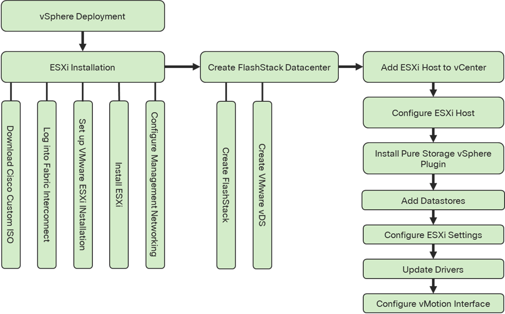
Several methods exist for installing ESXi in a VMware environment. These procedures focus on how to use the built-in keyboard, video, mouse (KVM) console and virtual media features in Cisco UCS Manager to map remote installation media to individual servers and connect to their boot logical unit numbers (LUNs).
Download Cisco Custom Image for ESXi 7.0
The VMware Cisco Custom Image will be needed for use during installation by manual access to the Cisco UCS KVM vMedia, or through a vMedia. If the Cisco Custom Image was not downloaded earlier, download it now by following these steps:
1. Click the following link: Cisco Custom ISO for UCS 4.1.2a.
2. You will need a user id and password on vmware.com to download this software.
3. Download the .iso file.
Log i to Cisco UCS 6454 Fabric Interconnect
The IP KVM enables the administrator to begin the installation of the operating system (OS) through remote media. It is necessary to log in to the Cisco UCS environment to run the IP KVM.
To log in to the Cisco UCS environment, follow these steps:
1. Open a web browser to https:// <<var_ucs_mgmt_vip>>
2. Click the Launch UCS Manager in the HTML section to pull up the UCSM HTML5 GUI.
3. Enter admin for the Username, and provide the password used during setup.
4. Within the UCSM click Servers -> Service Profiles and pick the first host provisioned as VM-Host-FC-01.
5. Click the KVM Console option within Actions and accept the KVM server certificate in the new window or browser tab that is spawned for the KVM session.
6. Click the link within the new window or browser tab to load the KVM client application.
Set Up VMware ESXi Installation
![]() Skip this step if you are using vMedia policies.
Skip this step if you are using vMedia policies.
To prepare the server for the OS installation, follow these steps on each ESXi host:
1. In the KVM window, click Virtual Media icon ![]() in the upper right of the screen.
in the upper right of the screen.
2. Click Activate Virtual Devices.
3. Click Virtual Media again and click Map CD/DVD.
4. Browse to the ESXi installer ISO image file and click Open.
5. Click Map Device.
6. Click the KVM tab to monitor the server boot.
7. Boot the server by selecting Boot Server and clicking OK, then click OK again.
To install VMware ESXi to the iSCSI bootable LUN of the hosts, follow these steps on each host:
1. On reboot, the machine detects the presence of the ESXi installation media. Choose the ESXi installer from the boot menu that is displayed.
2. After the installer is finished loading, press Enter to continue with the installation.
3. Read and accept the end-user license agreement (EULA). Press F11 to accept and continue.
4. Choose the LUN that was previously set up for the installation disk for ESXi and press Enter to continue with the installation.
5. Choose the appropriate keyboard layout and press Enter.
6. Enter and confirm the root password and press Enter.
7. The installer issues a warning that the selected disk will be repartitioned. Press F11 to continue with the installation.
8. From the KVM window, press Enter to reboot the server.
Set Up Management Networking for ESXi Hosts
Adding a management network for each VMware host is necessary for managing the host. To add a management network for the VMware hosts, follow the steps in this section on each ESXi host.
To configure the ESXi host with access to the management network, follow these steps:
1. After the server has finished rebooting, press F2 to customize the system.
2. Log in as root, enter the corresponding password, and press Enter to log in.
3. Click Troubleshooting Options.
4. Enable ESXi shell.
5. Enable SSH.
6. Hit Esc to exit.
7. Choose the Configure the Management Network option and press Enter.
8. Choose Network Adapters option leave vmnic0 selected, arrow down to vmnic1 and press space to choose vmnic1 as well and press Enter.
9. Choose the VLAN (Optional) option and press Enter.
10. Enter the <<var_ib_mgmt_vlan_id>> and press Enter.
11. From the Configure Management Network menu, select IPv4 Configuration and press Enter.
12. Choose the Set Static IP Address and Network Configuration option by using the space bar.
13. Enter <<var_vm_host_iSCSI_01_ip>> for the IPv4 Address for managing the first ESXi host.
14. Enter <<var_ib_mgmt_vlan_netmask_length>> for the Subnet Mask for the first ESXi host.
15. Enter <<var_ib_mgmt_gateway>> for the Default Gateway for the first ESXi host.
16. Press Enter to accept the changes to the IPv4 configuration.
17. Choose the DNS Configuration option and press Enter.
![]() Because the IP address is assigned manually, the DNS information must also be entered manually.
Because the IP address is assigned manually, the DNS information must also be entered manually.
18. Enter the IP address of <<var_nameserver_ip>> for the Primary DNS Server.
19. Optional: Enter the IP address of the Secondary DNS Server.
20. Enter the fully qualified domain name (FQDN) for the first ESXi host.
21. Press Enter to accept the changes to the DNS configuration.
22. Press Esc to exit the Configure Management Network submenu.
23. Press Y to confirm the changes and return to the main menu.
24. The ESXi host reboots. After reboot, press F2 and log back in as root.
25. Click Test Management Network to verify that the management network is set up correctly and press Enter.
26. Press Enter to run the test.
27. Press Enter to exit the window, and press Esc to log out of the VMware console.
28. Repeat the steps found in sections Set Up VMware ESXi Installation, Install ESXi, and Set Up Management Networking for ESXi Host for additional hosts provisioned, using appropriate values.
If a new Datacenter is needed for the FlashStack, follow these steps on the vCenter:
1. Connect to the vSphere Web Client and click Hosts and Clusters from the left side Navigator window or the Hosts and Clusters icon from the Home center window.
2. Right-click the vCenter icon and choose New Datacenter… from the drop-down list.
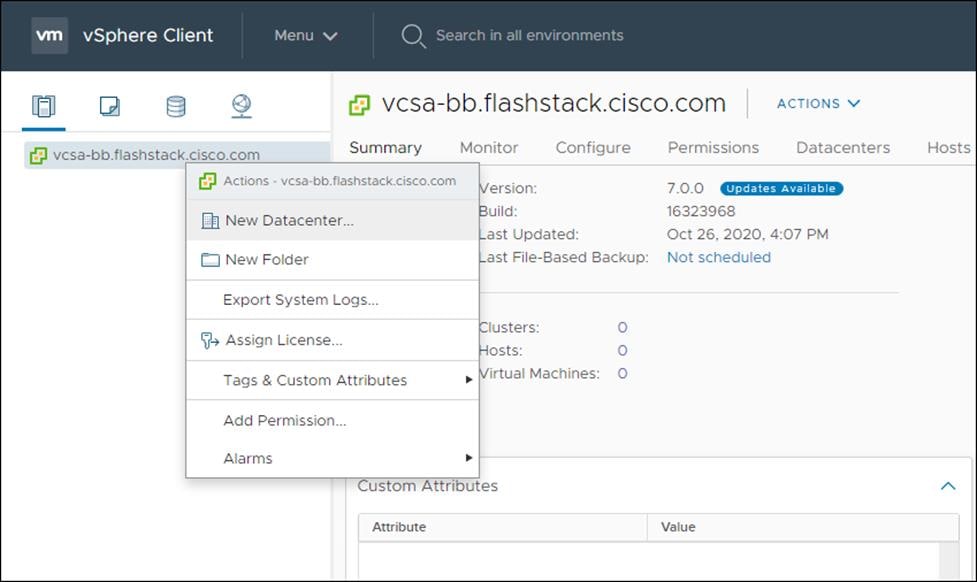
3. From the New Datacenter, enter in a Datacenter name and click OK.
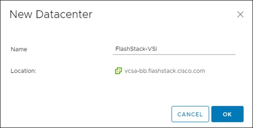
Create VMware vDS for vMotion and Application Traffic
The VMware vDS setup will consist of one vDS that are vMotion and Application traffic.
To configure the VMware vDS, follow these steps:
2. Right-click the FlashStack-VSI datacenter and choose Distributed Switch > New Distributed Switch…
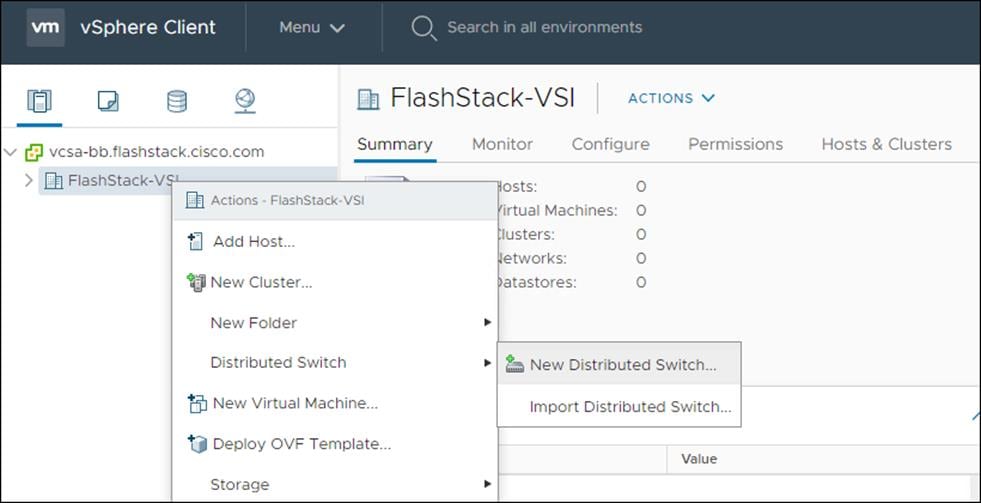
3. Give the Distributed Switch a descriptive name and click Next.
4. Make sure Distributed switch: 7.0.0 is selected and click Next.
5. Change the number of uplinks to 2. If VMware Network I/O Control is to be used for Quality of Service, leave Network I/O Control Enabled. Otherwise, Disable Network I/O Control. Enter VM-Traffic for the name of the default Port group to be created. Click Next.
6. Review the information and click Finish to complete creating the vDS.
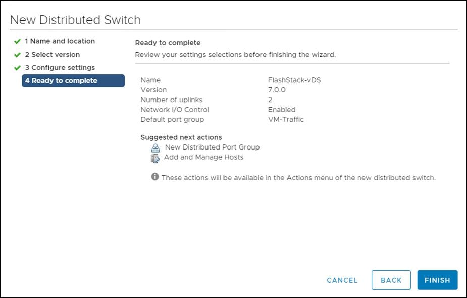
7. Right-click the newly created vDS on the left, and click Settings -> Edit Settings…
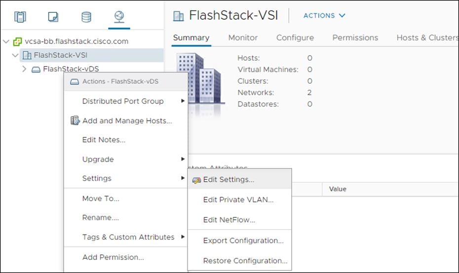
8. Change the MTU to 9000. The Discovery Protocol can optionally be changed to Link Layer Discovery Protocol and the Operation to Both. Click OK.
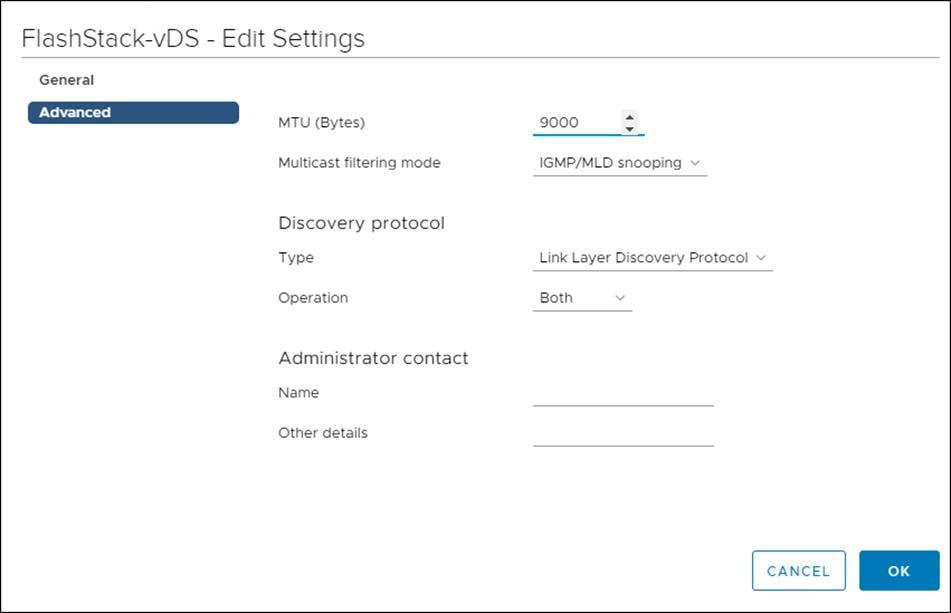
9. Expand the FlashStack VSI datacenter and the newly created vDS.
10. Right-click the VM-Traffic Distributed Port Group, and click Edit Settings…
11. Click VLAN, changing VLAN type from None to VLAN, and enter in the appropriate VLAN number for the VM-Traffic network.
12. Click OK to save the changes.
13. Right-click and click Distributed Port Group -> New Distributed Port Group…
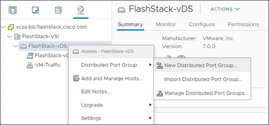
14. Name the new Port Group vMotion and click Next.
15. Change the VLAN type from None to VLAN, choose the VLAN ID appropriate for your vMotion traffic, and check the box for the Customize default policies configuration under the Advanced section.
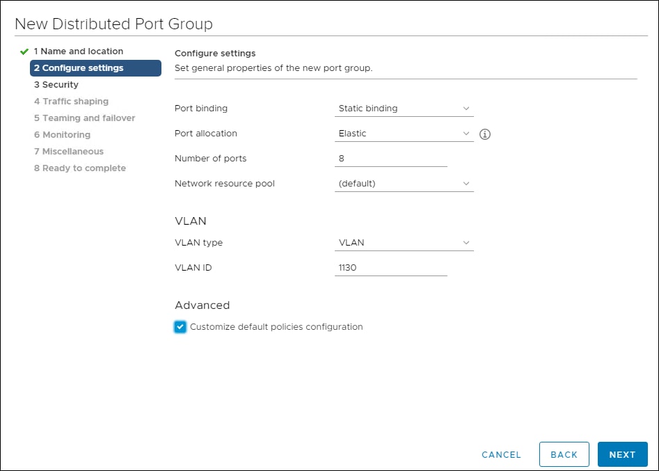
16. Click Next.
17. Click Next through the Security and Traffic Shaping sections.
18. Within the Teaming and failover section move Uplink 1 to the Standby uplinks section.
![]() The movement of Uplink 1 to standby is guiding vMotion traffic to stay within the B side fabric contained within Uplink 2 to prevent unnecessary traffic hops up into the Nexus switch to traverse between Fabric Interconnects
The movement of Uplink 1 to standby is guiding vMotion traffic to stay within the B side fabric contained within Uplink 2 to prevent unnecessary traffic hops up into the Nexus switch to traverse between Fabric Interconnects
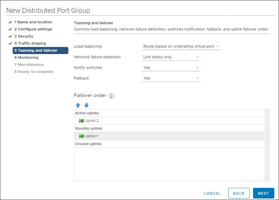
19. Click Next.
20. Click Next past Monitoring, Miscellaneous, and Edit additional settings sections.
21. Review the Ready to complete section.
22. Click Finish to create the Distributed Port Group.
Add the VMware ESXi Hosts Using the VMware vSphere Web Client
To add the VMware ESXi Hosts using the VMware vSphere Web Client, follow these steps:
1. From the Hosts and Clusters tab, right-click the new or existing Datacenter within the Navigation window and choose New Cluster… from the drop-down list.
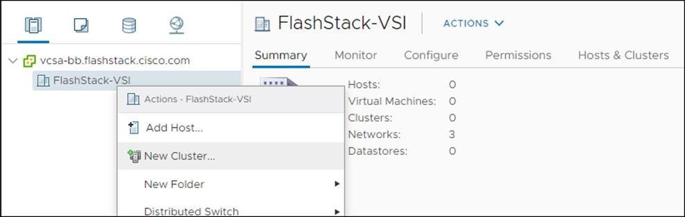
2. Enter a name for the new cluster, enable vSphere DRS and vSphere HA, leaving all other options with defaults.
3. Click OK to create the cluster.
4. Right-click the newly created cluster and choose the Add Host… drop-down list.
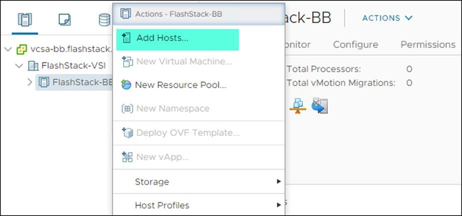
5. Enter the IP or FQDN, User Name, and password of the ESXi hosts and click Next.
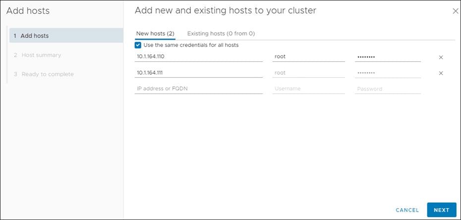
6. Click Yes in the Security Alert pop-up to confirm the host’s certificate.
7. Click Next past the Host summary dialogue.
8. Provide a license by clicking the green + icon under the License title, choose an existing license, or skip past the Assign license dialogue by clicking Next.
9. Leave lockdown mode Disabled within the Lockdown mode dialogue window and click Next.
10. Skip past the Resource pool dialogue by clicking Next.
11. Confirm the Summary dialogue and add the ESXi host to the cluster by clicking Next.
To claim vCenter in Intersight, follow these steps:
1. Open a browser to Cisco Intersight, https://intersight.com and log in to your Intersight account.
2. Click Admin > Devices.
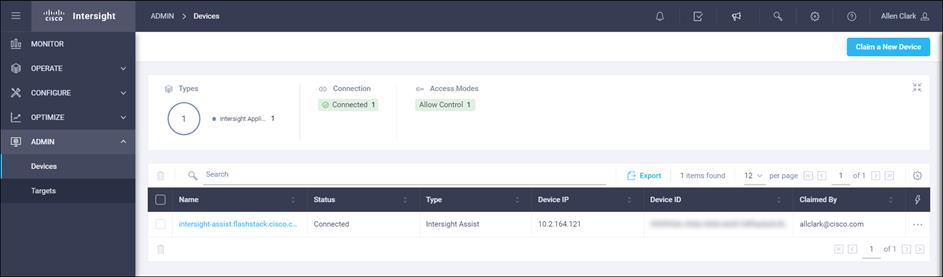
3. Click Claim a New Device and choose Claim Though Intersight Assist.
4. Set Type to VMware vCenter.
5. Enter vCenter Hostname/ IP address and credentials.
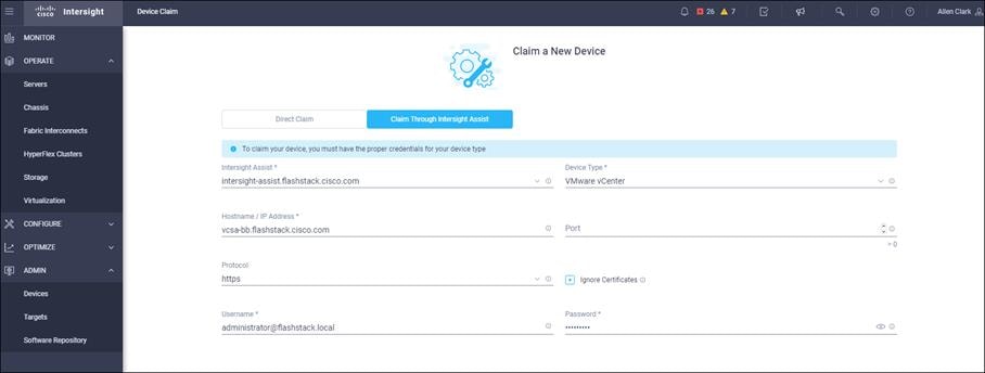
6. Click Claim.
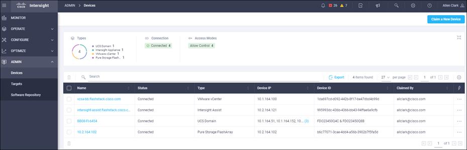
Intersight Orchestration will be used to create a vmfs 6 datastore to place swap and driver files.
![]() Creating vVol datastores is explained in section Pure Storage vSphere Client Plugin.
Creating vVol datastores is explained in section Pure Storage vSphere Client Plugin.
1. Click Configure -> Orchestration.
2. Click New VMFS Datastore.
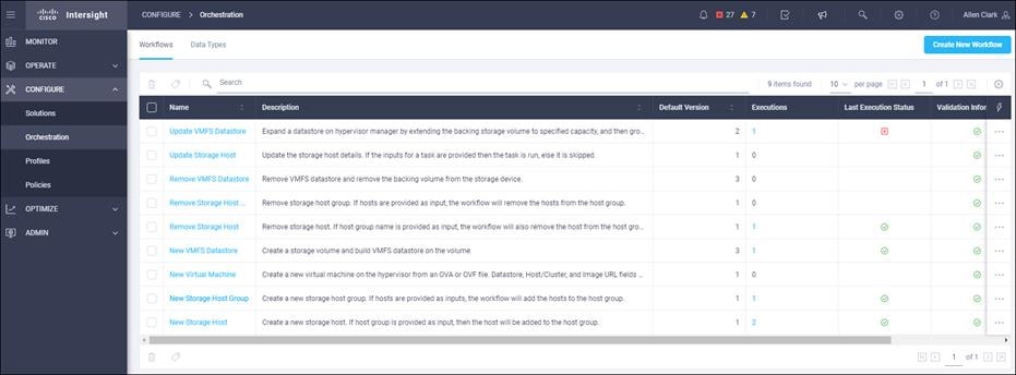
3. Click Execute.
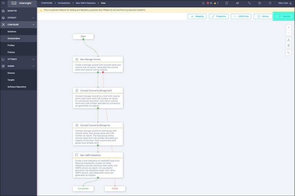
4. Choose the appropriate Organization.
5. Choose the appropriate Pure Storage device.
6. Enter the name of the Volume that will appear on the Pure Storage Array: ESXi-Swap.
7. Enter Volume size and units.
8. Choose Storage Host Group: VM-AMD-Host-Group.
9. Choose an unused LUN Number.
10. Choose the appropriate Hypervisor Manger, and Datacenter.
11. Enter the name of the Datastore that will appear in vSphere.
12. Click VMFS Version VMFS-6.
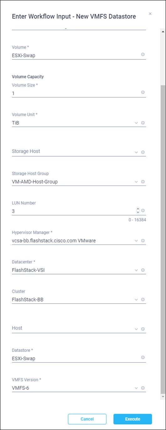
13. Click Execute.
Pure Storage vSphere Client Plugin
The Pure Storage vSphere Client Plugin will be accessible through the vSphere Client after registration through the Pure Storage Web Portal.
To access the Pure Storage vSphere Client Plugin, follow these steps:
1. Go to Settings > Software.
2. Click the edit icon in the vSphere Plugin panel.
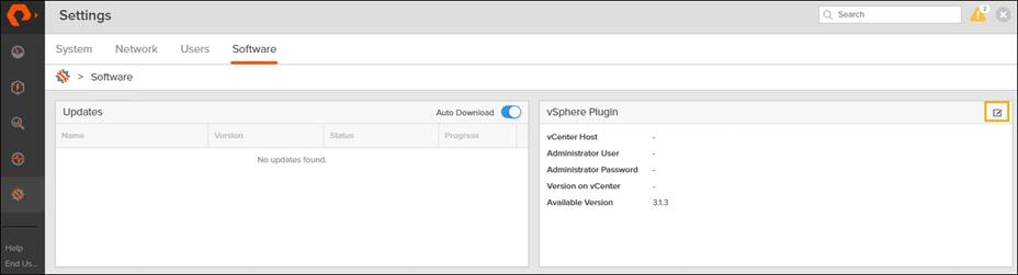
3. Enter the vCenter information in the pop-up window and click Save.
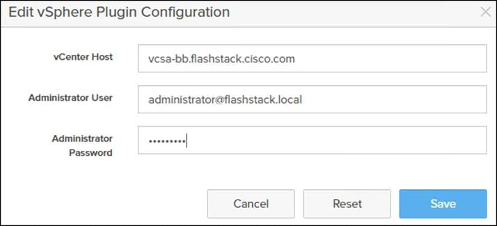
4. After the discovery completes. Click install.
5. In vCenter, click Pure Storage.
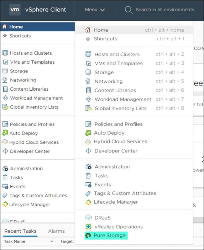
6. Click Authenticate with Pure1.
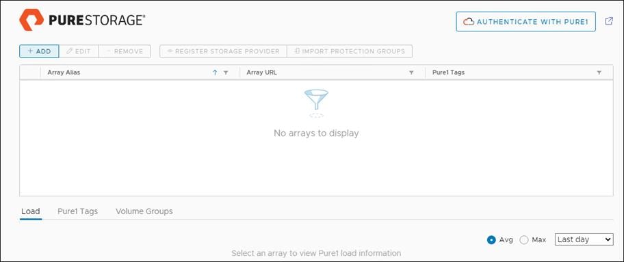
7. Input your Pure1 JWT (link).
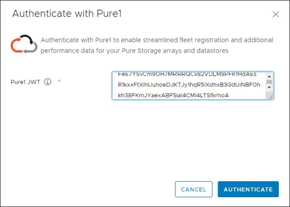
8. Click Authenticate.
9. Click Add.
10. Click Import Arrays from Pure1 and input the Username and Password.
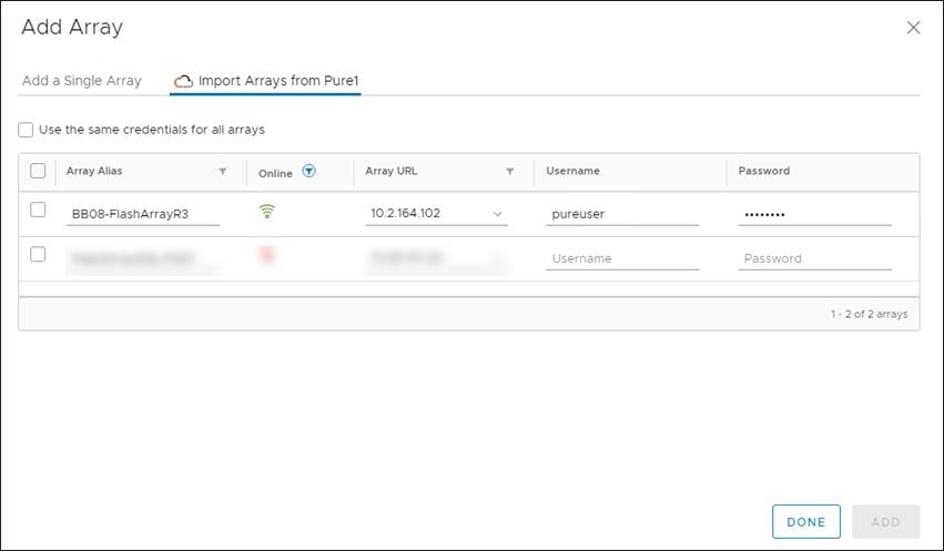
11. Click Done.
12. Click the newly added array.
13. Click Register Storage Provider.
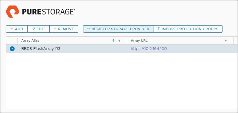
14. Enter Username and Password.
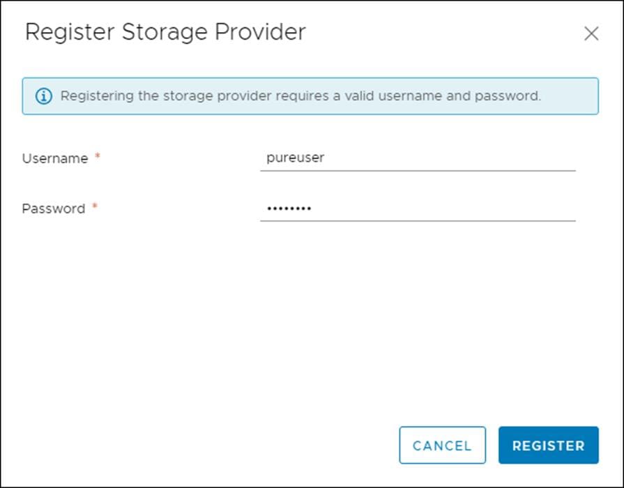
15. Click Register.
To create the vVol datastore, follow these steps:
1. In vCenter, click Host and Clusters.
2. Right-click the FlashStack Cluster and click Pure Storage -> Create Datastore.
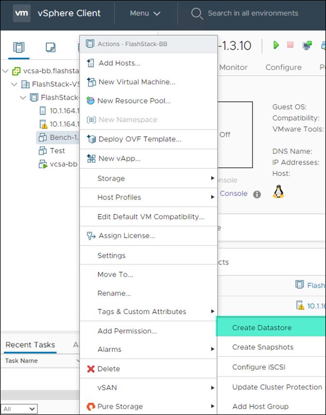
3. Click vVol.
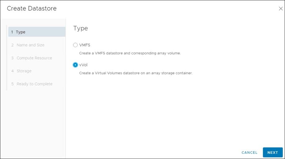
4. Click Next.
5. Enter a Datastore Name.
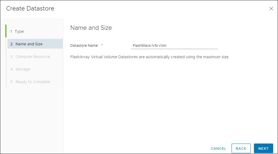
6. Click Next.
7. Click the Cluster under Compute Resources.
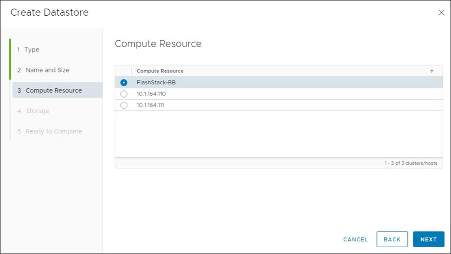
8. Click Next.
9. Click the Registered FlashArray.
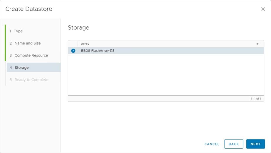
10. Click Next.
11. Review the information and click Finish.
A couple of base settings are needed for stability of the vSphere environment, as well as optional enablement of SSH connectivity to each host for the updating of drivers.
To configure ESXi settings, follow these steps:
1. Choose the first ESXi host to configure with standard settings.
2. Click the Configure tab and choose Time Configuration within the options on the left under System and click Edit for Network Time Protocol.
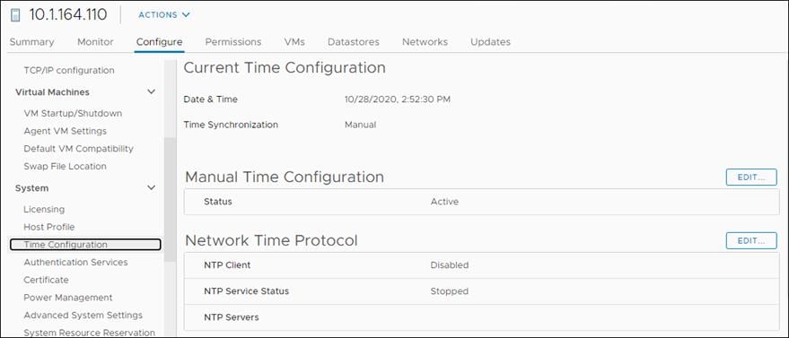
3. Check Enable, enter <<var_oob_ntp>> for the NTP Servers, click Start and stop with port usage for NTP Service Startup Policy, and click Start within NTP Service Status. Click OK to submit the changes.
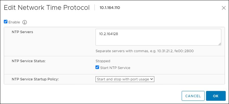
4. Click System Swap in the System section within the Configure tab and click Edit.
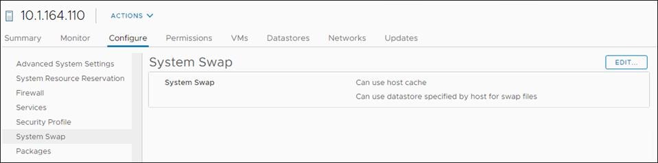
5. Check the Can use datastore: option and selection the ESXi-Swap datastore.
6. Repeat these steps on each ESXi host being added into the cluster.
To configure the vSwitch0, follow these steps:
1. From the Hosts and Clusters, choose the first host and click the Configure tab for that host.
2. Click Virtual Switches under the Networking section
3. Click Manage Physical Adapters for Standard Switch: vSwitch0
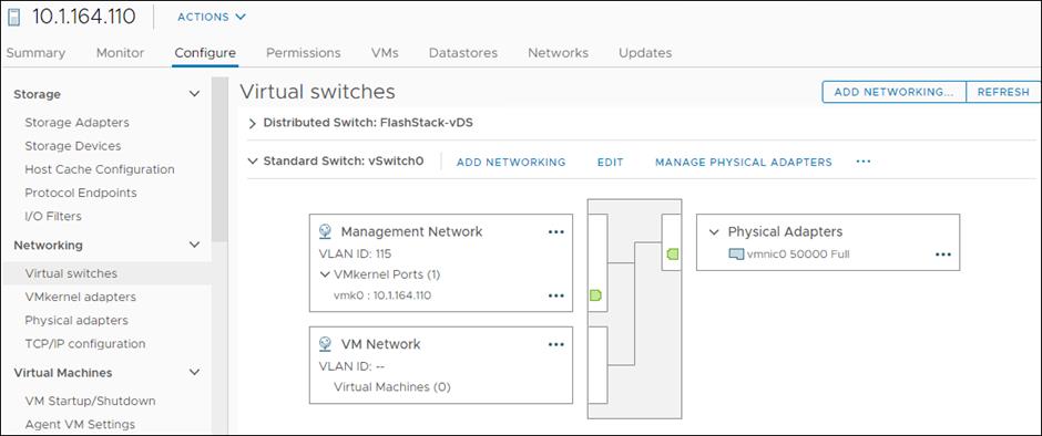
4. Click the Green + sign under Assigned adapters.
5. Click vmnic1 and click OK.
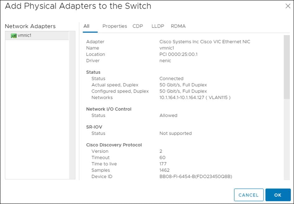
6. Confirm that vnmic0 and vmnic1 are listed as Active adapters and click OK.
To add the ESXi hosts to each vDS, follow these steps:
1. Within the Networking tab of the Navigator window, right-click the FlashStack-vDS vDS and click Add and Manage Hosts…
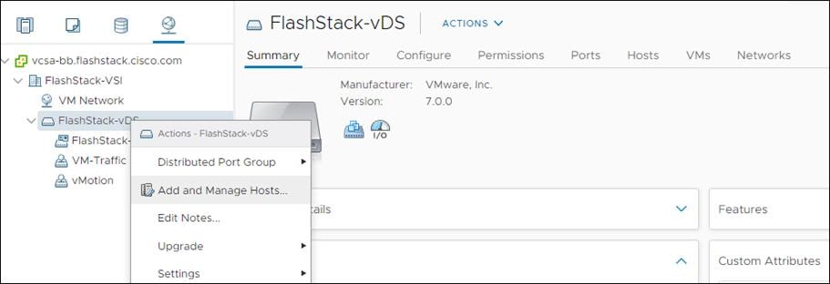
2. Leave Add hosts selected and click Next.
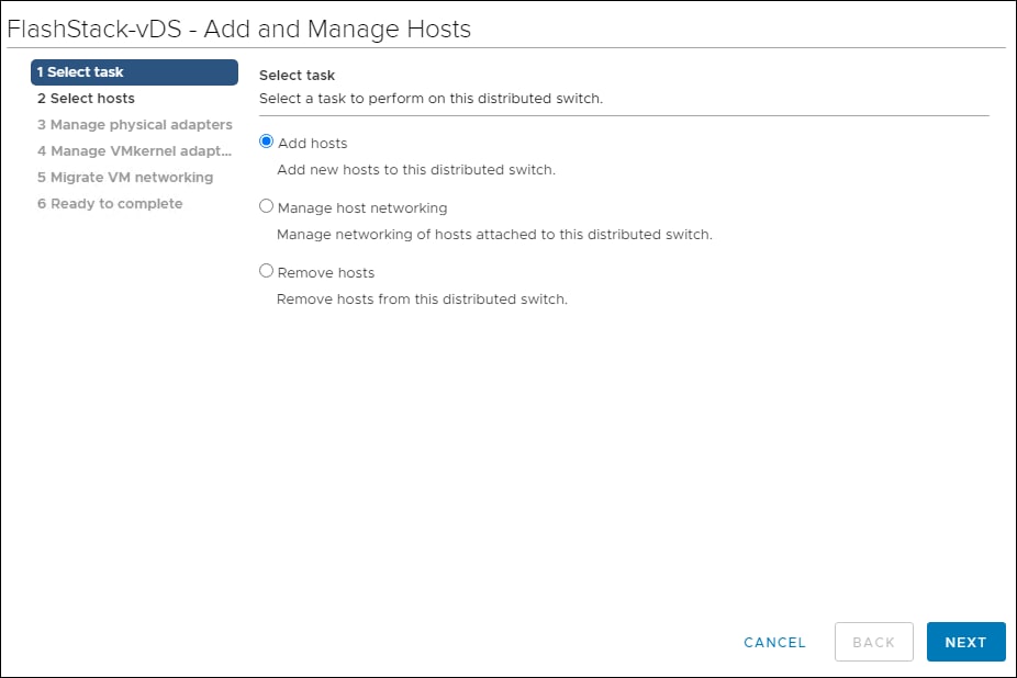
3. Click the green + icon next to New hosts…
4. In Select New Hosts, choose the hosts to be added, and click OK to begin joining them to the vDS.
5. Click Next.
6. Choose vmnic2 on each host and click Assign uplink. Choose Uplink 1 and click OK. Choose vmnic3 on each host and click Assign uplink. Choose Uplink 2 and click OK. If more than one host is being connected to the vDS, use the Apply this uplink assignment to the rest of the hosts checkbox.
![]() It is important to assign the uplinks as shown below. This allows the port groups to be pinned to the appropriate Cisco UCS fabric.
It is important to assign the uplinks as shown below. This allows the port groups to be pinned to the appropriate Cisco UCS fabric.
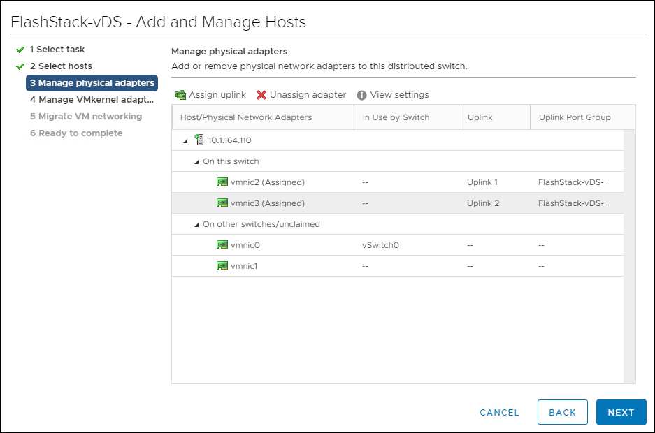
7. Click Next.
8. Do not migrate any VMkernel ports and click Next.
9. Do not migrate any VM ports and click Next.
10. Click Finish to complete adding the ESXi host(s) to the vDS.
Create vMotion VMkernel Adapters
A vMotion VMkernel adapter will be created for FlashStack infrastructure to keep vMotion traffic independent of management traffic. To create the vMotion VMkernel adapters, follow these steps:
1. From the Hosts and Clusters, choose the first host and click the Configure tab for that host.
2. Choose the VMkernel adapters option within the Networking section of Configure.
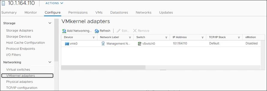
3. Click the first icon under VMkernel adapters to Add host networking.
4. Leave the connection type selected as VMkernel Network Adapter and click Next.
5. Choose Select an existing network then click Next.
6. Choose the vMotion network and click OK.
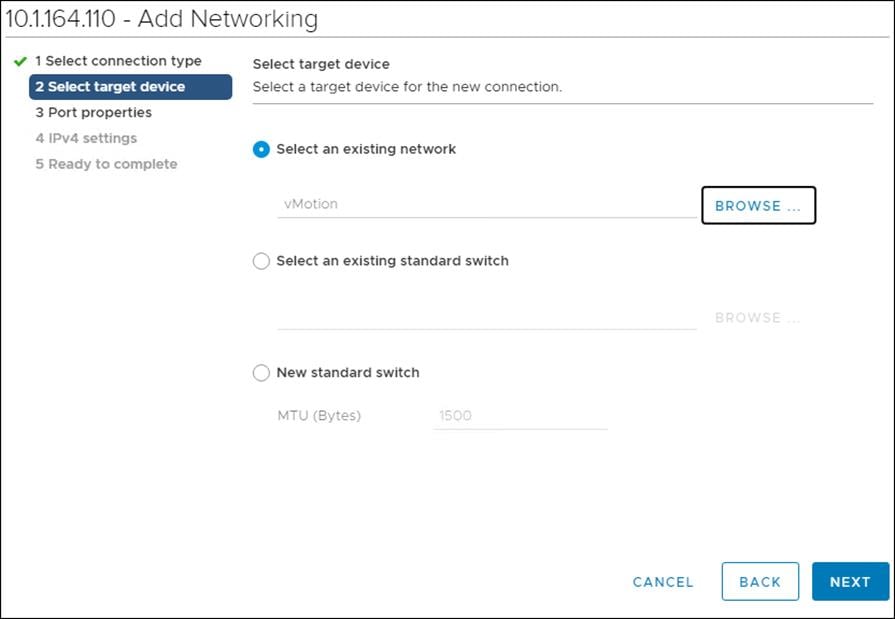
7. Click Next.
8. Choose the vMotion from the Available services and click Next.
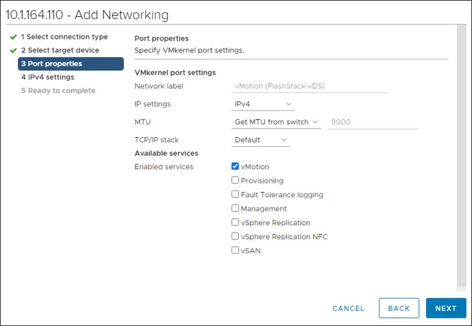
9. Provide and IP address and subnet mask within the vMotion network.
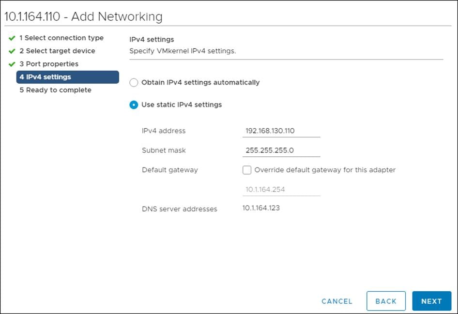
10. Click Next.
11. Review the settings and click Finish to create the VMkernel adapter.
12. Optionally, create two more vMotion VMkernel NICs to increase the speed of multiple simultaneous vMotion on this solution’s 50GE vNICs.
13. Repeat steps 1-12 to create vMotion VMkernel adapters for each additional ESXi host.
Configure iSCSI A vSwitch and VMkernel
1. From the Hosts and Clusters, choose the first host and click the Configure tab for that host.
2. Click Virtual switches.
3. Choose the iScsiBootvSwitch.
4. Click Edit.
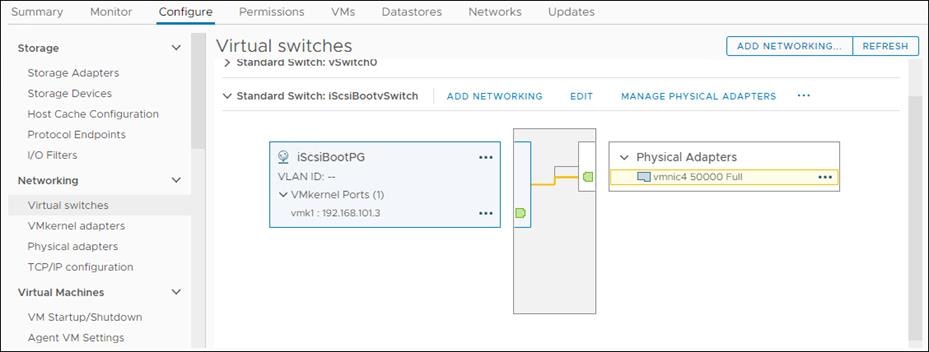
5. From Properties, change the MTU from 1500 to 9000 and click OK.
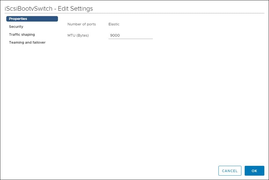
6. Click vmk1 entry.
7. Click the … and click Edit Settings.
8. From Port properties change the MTU value to 9000.
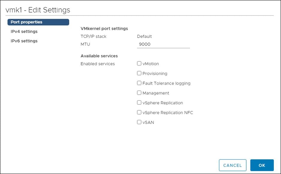
9. Click the IPv4 Settings.
10. Change the IPv4 settings from the Cisco UCS Manager iSCSI-A-Pool assigned IP to one that is not in the IP block.
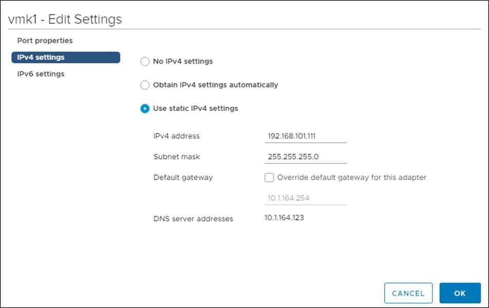
11. Click OK to apply the changes.
Configure iSCSI B vSwitch and VMkernel
1. From the Hosts and Clusters, choose the first host and click the Configure tab for that host.
2. Click Virtual switches.
3. Click Add Networking.
4. Choose VMkernel Network Adapter.
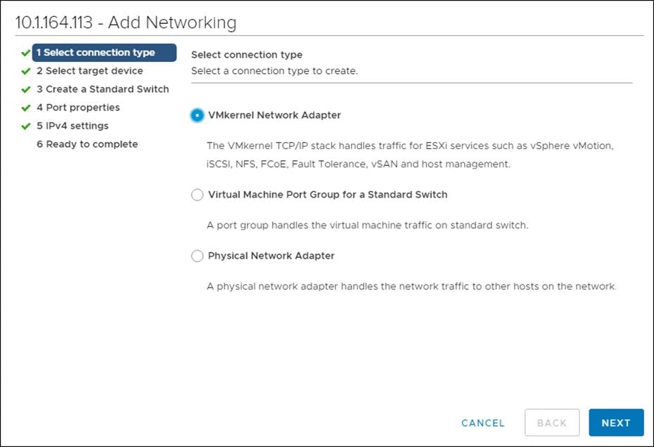
5. Click Next.
6. Choose New standard switch and set MTU to 9000.
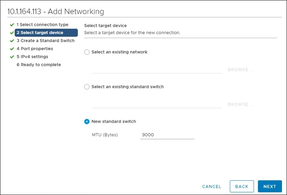
7. Click Next.
8. Click the Green + sign.
9. Choose vmnic5.
10. Ensure vmnic5 is listed as an Active adapter.
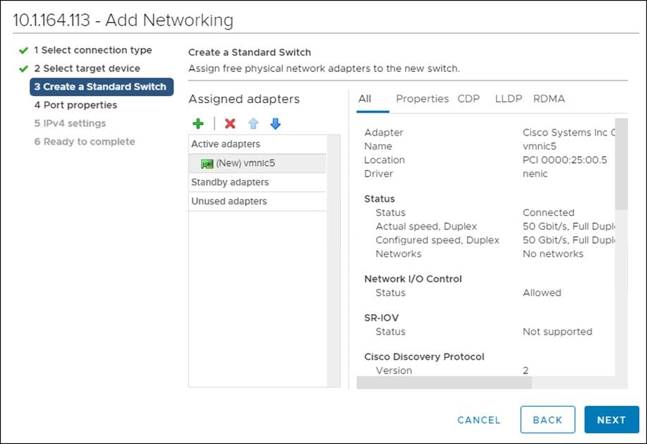
11. Click Next.
12. Set the network label to VMkernel-iSCSI-B.
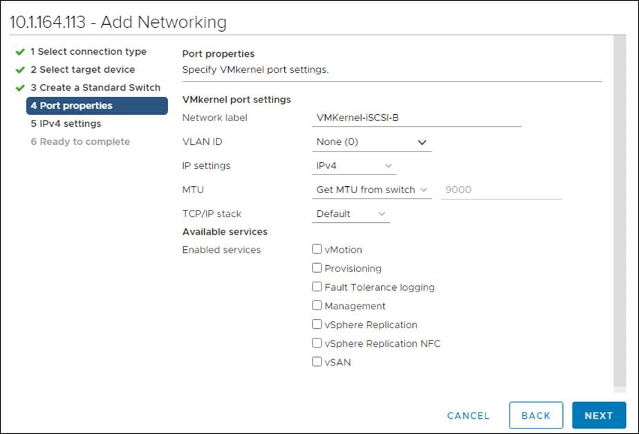
13. Click Next.
14. Set the option to Use static IPv4 settings.
15. Enter a valid IP address and subnet mask that is outside the UCS-iSCSI-Pool-B.
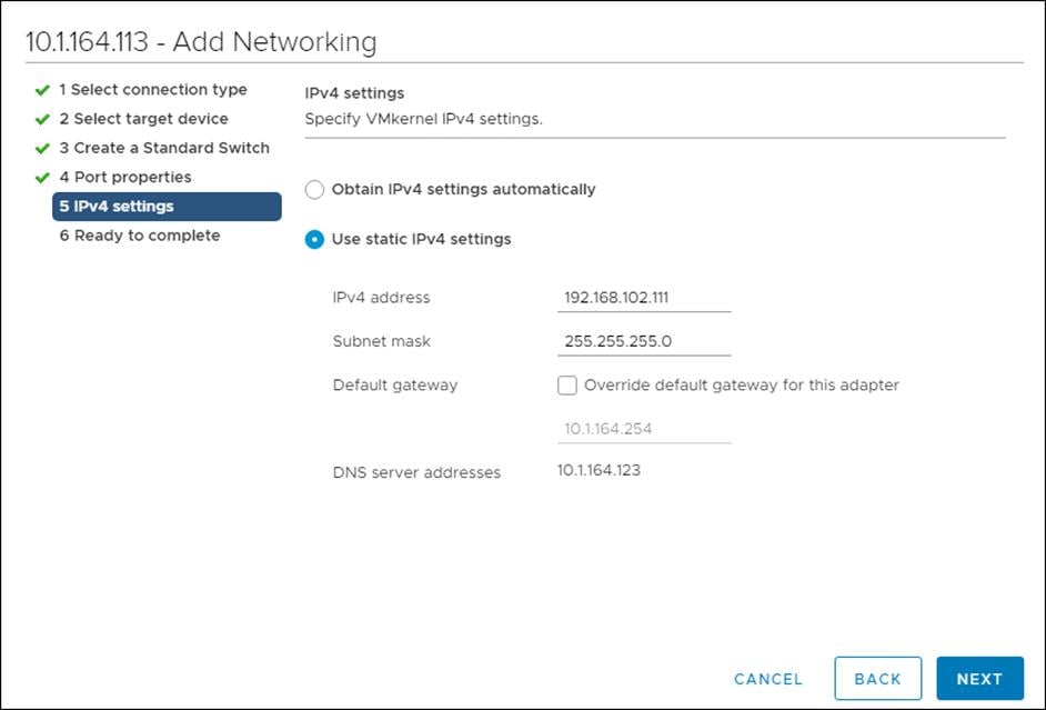
16. Click Next.
17. Review the configuration and click Finish.
18. Click Edit for Standard Switch: vSwtich1.
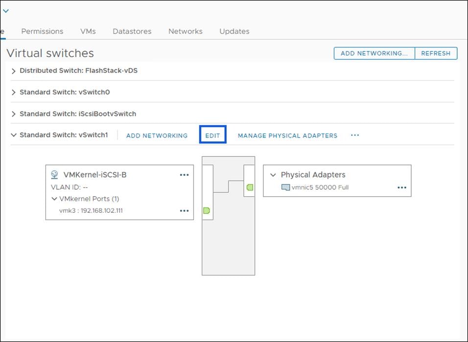
19. Click Security.
20. Set Promiscuous mode, MAC address changes, and Forged transmits to reject.
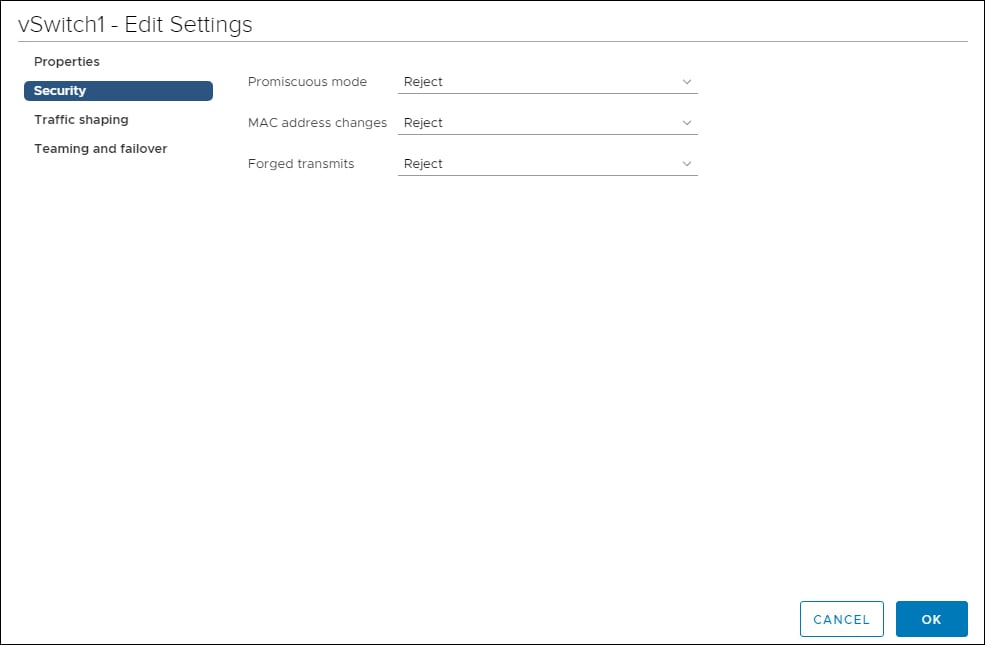
21. Click OK.
Configure iSCSI Options for Pure Storage FlashArray//X50 R3
To configure the iSCSI options for Pure Storage FlashArray//X50 R3, follow these steps:
1. Right-click the host and click Pure Storage > Configure iSCSI.
2. Choose the FlashArray//X50 R3.
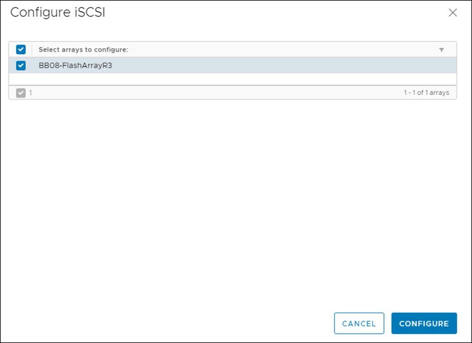
3. Click Configure.
This section provides an example QOS where the iSCSI traffic is placed in a higher priority queue than vMotion, Management, or Application data. This can be used as a framework to understand the process, but each deployment should consider the QoS requirements for their unique environments when planning and implementing an end to end QoS policy. Make sure that the specific QoS configuration northbound of the Cisco UCS conforms to the QoS design and planning of the network as a whole.
To configure the QoS class, follow these steps:
1. In Cisco UCS Manager, click the LAN tab in the navigation pane.
2. Click the QoS System Class.
3. Enable the Gold Priority.
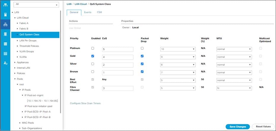
4. Click Save Changes.
5. Click OK.
To create the QoS policy, follow these steps:
1. In Cisco UCS Manager, click the LAN tab in the navigation pane.
2. Click Policies > Root.
3. Click QoS Policies.
4. Click Add.
5. Name the Policy and set the Priority to Gold.
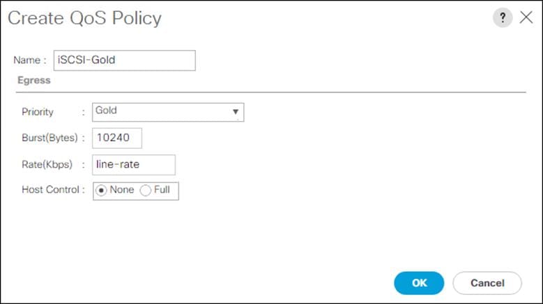
6. Click OK, then click OK again.
To configure the QoS class, follow these steps:
1. In Cisco UCS Manager, click the LAN tab in the navigation pane.
2. Click Policies > Root.
3. Expand vNIC Templates and choose vNIC Template vNIC_iSCS-A.
4. Set QoS Policy to iSCS-Gold.
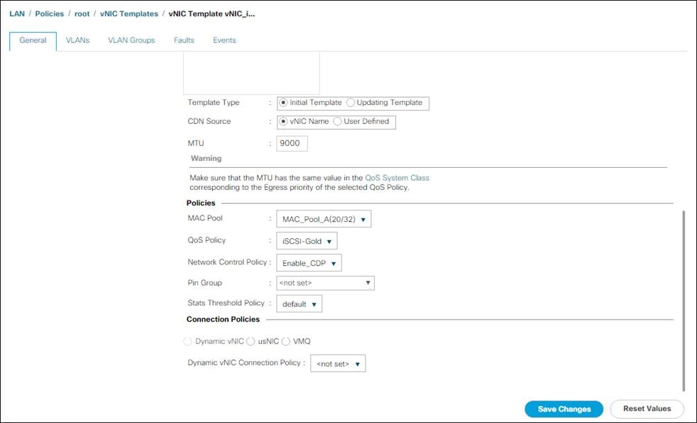
5. Click Save Changes.
6. Repeat steps 3-6 but choose template vNIC Template vNIC_iSCSI-B.
Allen Clark, Technical Marketing Engineer, Cisco Systems, Inc.
For their support and contribution to the design, validation, and creation of this Cisco Validated Design, the authors would like to thank:
● John George, Technical Marketing Engineer, Cisco Systems, Inc.
● Craig Waters, Solutions Architecture / Product Management, Pure Storage, Inc.
For comments and suggestions about this guide and related guides, join the discussion on Cisco Community at https://cs.co/en-cvds.