Performance Tuning for Cisco UCS C125 Rack Server Nodes with AMD Processors (White Paper)
Available Languages
Bias-Free Language
The documentation set for this product strives to use bias-free language. For the purposes of this documentation set, bias-free is defined as language that does not imply discrimination based on age, disability, gender, racial identity, ethnic identity, sexual orientation, socioeconomic status, and intersectionality. Exceptions may be present in the documentation due to language that is hardcoded in the user interfaces of the product software, language used based on RFP documentation, or language that is used by a referenced third-party product. Learn more about how Cisco is using Inclusive Language.
The basic input and output system (BIOS) tests and initializes the hardware components of a system and boots the operating system from a storage device. A typical computational system has several BIOS settings that control the system’s behavior. Some of these settings are directly related to the performance of the system.
This document explains the BIOS settings that are valid for the Cisco Unified Computing System™ (Cisco UCS®) servers with AMD processors: the Cisco UCS C125 M5 Rack Server Node using the AMD EPYC processor. It describes how to optimize the BIOS settings to meet requirements for best performance and energy efficiency for the Cisco UCS C125 M5 node.
This document also discusses the BIOS settings that can be selected for various workload types on Cisco UCS C125 M5 nodes that use AMD EPYC CPUs. Understanding the BIOS options will help you select appropriate values to achieve optimal system performance.
This document does not discuss the BIOS options for specific firmware releases of Cisco UCS servers. The settings demonstrated here are generic.
The process of setting performance options in your system BIOS can be daunting and confusing, and some of the options you can choose are obscure. For most options, you must choose between optimizing a server for power savings or for performance. This document provides some general guidelines and suggestions to help you achieve optimal performance from your Cisco UCS C125 M5 Rack Server Node that uses AMD EPYC family CPUs.
This document focuses on two main scenarios: how to tune the BIOS for high performance and for low latency.
With the latest multiprocessor, multicore, and multithreading technologies in conjunction with current operating systems and applications, today's Cisco UCS servers based on the AMD EPYC processor deliver the highest levels of performance, as demonstrated by the numerous industry-standard benchmark publications from the Standard Performance Evaluation Corporation (SPEC).
Cisco UCS servers with standard settings already provide an optimal ratio of performance to energy efficiency. However, through BIOS settings you can further optimize the system with higher performance and less energy efficiency. Basically, this optimization operates all the components in the system at the maximum speed possible and prevents the energy-saving options from slowing down the system. In general, optimization to achieve greater performance is in most cases associated with increased consumption of electrical power. This document explains how to configure the BIOS settings to achieve optimal computing performance.
The BIOS offers a variety of options to reduce latency. In some cases, the corresponding application does not make efficient use of all the threads available in the hardware. To improve performance, you can disable threads that are not needed (hyperthreading) or even cores in the BIOS to reduce the small fluctuations in the performance of computing operations that especially occur in some high-performance computing (HPC) applications and analytical database applications. Furthermore, by disabling cores that are not needed, you can improve turbo-mode performance in the remaining cores under certain operating conditions.
Energy-saving functions, whose aim is to save energy whenever possible through frequency and voltage reduction and through the disabling of certain function blocks and components, also have a negative impact on response time. The higher the settings for the energy saving modes, the lower the performance. Furthermore, in each energy-saving mode, the processor requires a certain amount of time to change back from reduced performance to high performance.
This document explains how to configure the power and energy saving modes to reduce system latency. The optimization of server latency, particularly in an idle state, results in substantially greater consumption of electrical power.
You can configure the processor and BIOS settings either through the Cisco UCS Manager GUI, for a system managed with the Cisco UCS platform, or through the Cisco® Integrated Management Controller (IMC), for a standalone system. Figure 1 shows the settings using Cisco UCS Manager, and Figure 2 and Figure 3 show the settings using the IMC.
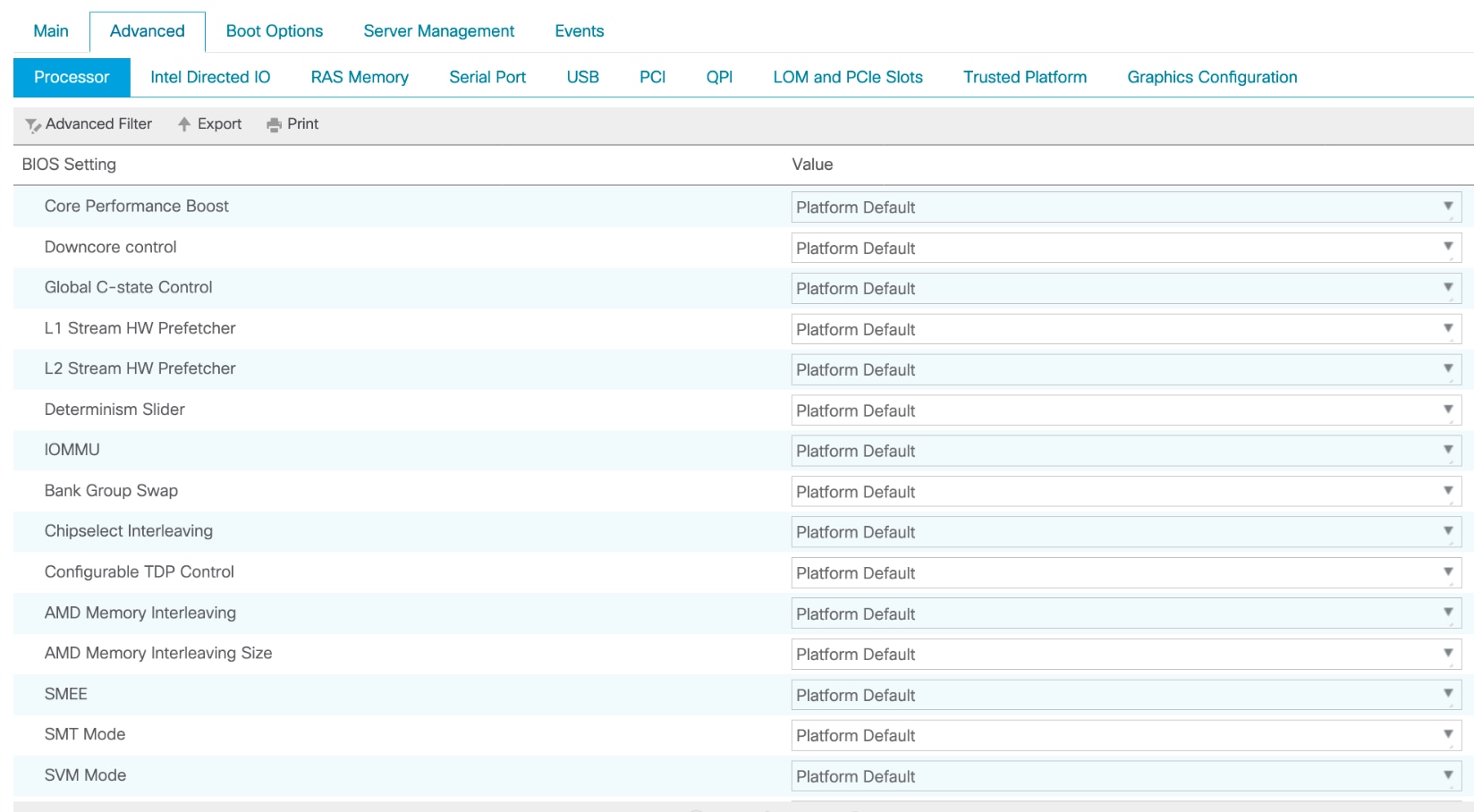
BIOS tokens available for configuration through Cisco UCS Manager
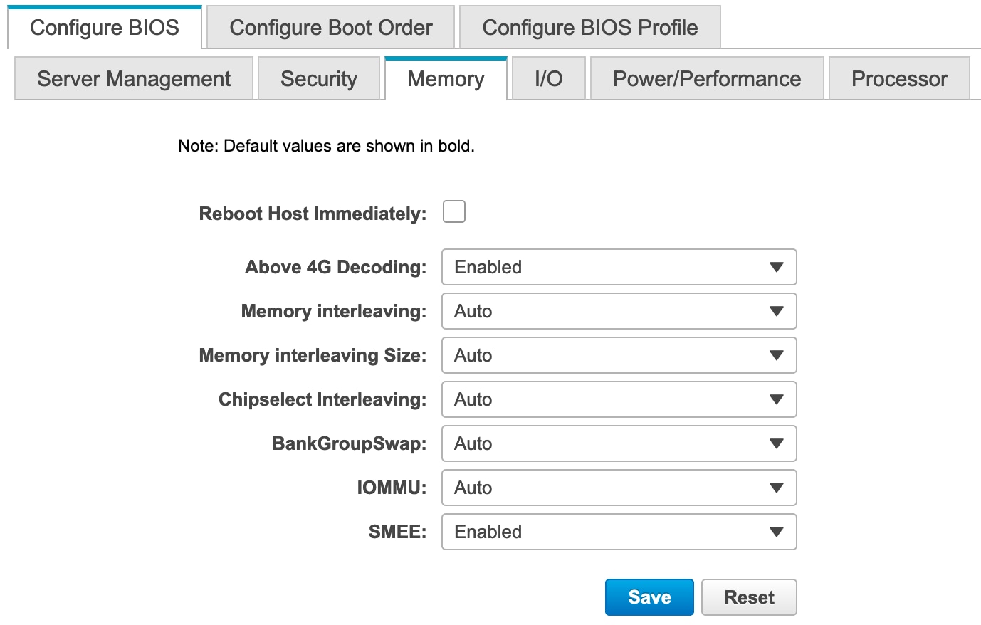
BIOS tokens for Memory available for configuration through Cisco IMC (screen 1)
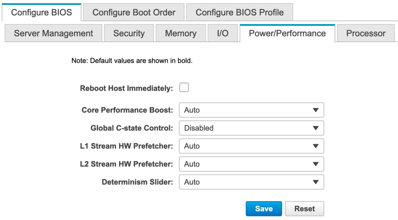
BIOS tokens for Power/Performance available for configuration through Cisco IMC (screen 2)
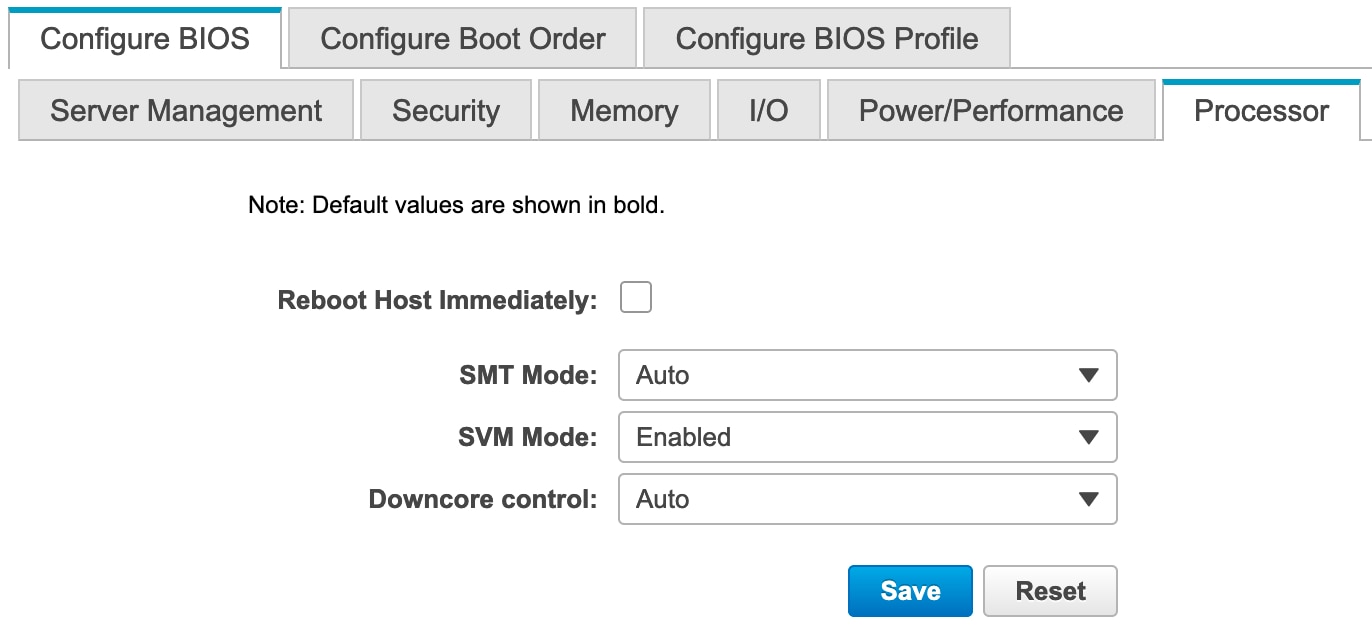
BIOS tokens for Processor available for configuration through Cisco IMC (screen 3)
Simultaneous multithreading option: SMT Mode
You can set the simultaneous multithreading (SMT) option to enable or disable logical processor cores on processors that support the AMD SMT Mode option. When SMT Mode is set to Auto (Enabled), each physical processor core operates as two logical processor cores and allows multithreaded software applications to process threads in parallel within each processor.
You should test the CPU hyperthreading option both enabled and disabled in your specific environment. If you are running a single-threaded application, you should disable hyperthreading.
SMT Mode can be set to either of the following values:
● Auto: The processor allows parallel processing of multiple threads.
● Disabled: The processor does not permit hyperthreading.
Core thread enablement option: Downcore control
The core thread enablement option enables you to disable cores. This option may affect the pricing of certain software packages that are licensed by the core. You should consult your software license and software vendor about whether disabling cores qualifies you for any particular pricing policies. Set the “Downcore control” option for core thread enablement to Auto if pricing policy is not a concern for you.
AMD Core Performance Boost controls whether the processor transitions to a higher frequency than the processor's rated speed if the processor has available power and is within temperature specifications.
Processor power and performance optimization
The AMD CPU implements enhanced features that continuously monitor operational conditions (temperature, current, voltage, frequency, and power) and workload requirements to achieve maximum performance with the lowest possible power consumption. These features, enabled by enhanced system design and optimal environment conditions, work in combination to improve performance while maintaining baseline performance.
Because these features optimize performance continuously and can adjust frequency in 25-MHz steps, performance from run to run between different system implementations can vary. The primary elements of this variance are system thermal solution performance and system ambient temperature. The CPU includes enhanced frequency control features that are tuned to provide the highest operating frequency on the active CPU cores that meet required voltage, current, and power maximums.
The BIOS Determinism Slider option specifies the mode of operation. The available values are as follows:
● Performance: This is the default setting. The processor operates at a capped performance level, which is the maximum operating state. This setting reduces sample-to-sample variance.
● Power: The processor operates as close to the thermal design power (TDP) as possible, proportionally increasing performance.
● Auto: This setting is equal to the Performance option.
The Secure Virtual Machine (SVM) mode enables processor virtualization features and allows a platform to run multiple operating systems and applications in independent partitions. The AMD SVM mode can be set to either of the following values:
● Disabled: The processor does not permit virtualization.
● Enabled: The processor allows multiple operating systems in independent partitions.
If your application scenario does not require virtualization, then disable AMD virtualization technology. With virtualization disabled, also disable the AMD I/O Memory Management Unit (IOMMU) option. It can cause differences in latency for memory access.
Memory interleaving is a technique that CPUs use to increase the memory bandwidth available for an application. Without interleaving, consecutive memory blocks, often cache lines, are read from the same memory bank. Software that reads consecutive memory thus will need to wait for a memory transfer operation to complete before starting the next memory access. With memory interleaving enabled, consecutive memory blocks are in different banks and so can all contribute to the overall memory bandwidth a program can achieve.
NPS is a new feature in 2nd Gen AMD EPYC processors called NUMA nodes Per Socket. With this feature, a single socket can be divided into up to 4 NUMA nodes. Each NUMA node can only use its assigned memory controllers.
This setting lets you specify the number of desired NUMA nodes per socket. Second-generation AMD EPYC Rome processors support a varying number of NUMA Nodes per Socket depending on the internal NUMA topology of the processor. Socket interleave (NPS0) will attempt to interleave the two sockets together into one NUMA node. In one-socket servers, the number of NUMA Nodes per socket can be 1, 2 or 4 though not all values are supported by every processor. Applications that are highly NUMA optimized can improve performance by setting the number of NPS to a supported value greater than 1.
The following settings are available:
● Channel Interleave* (NPS4): The processor is partitioned into four NUMA domains. Each logical quadrant of the processor is a NUMA domain and Memory is interleaved across the two memory channels in each quadrant. It is recommended for highly NUMA aware workloads such as SPECCPU, HPC and other highly parallel wokloads that use localized memory traffic: that is, traffic evenly distributed across non-uniform memory access (NUMA) nodes. This configuration provides the highest throughput and lowest average latency for memory transactions.
● None (NPS2): With this setting, the processor is partitioned into two NUMA domains. Half the cores and half the memory channels connected to the processor are grouped together into one NUMA domain. Memory is Interleaved across the four memory channels in each NUMA domain. NPS2 is best for generic workload. Though, specific workloads/applications might need more testing to tune the desired performance.
Note: NPS2 is preferred configuration to achieve max 200Gb/s performance, it provides a compromise between memory latency and memory bandwidth for the NIC.
● Die Interleave* (NPS1): This setting is enabled by default (Auto). The processor is a single NUMA domain, i.e. all cores on the processor, all memory connected to it and all PCIe devices connected to the processor are in one NUMA domain. Memory is interleaved across the eight memory channels. For a single-socket system, this option creates a single NUMA node and single memory domain as it combines all the memory attached to the four dies in the socket, producing a non-NUMA configuration. For a two-socket system, this option creates two NUMA nodes and improves performance for applications that are tuned for two NUMA nodes. NPS1 also best option for generic workload. If your workload is non-NUMA aware or suffers when NUMA complexity increases, you can experiment NPS1.
● Socket* (NPS0) : With this setting, memory across both sockets is seen as a single memory domain, producing a non-NUMA configuration. This option generally is not recommended for the best performance.
● Auto: This setting is equal to the Die Interleave option (NPS1).
*Note : AMD EPYC 7002 Series Processors are available in different core counts per processor and not all of them can support all NPS settings. See https://developer.amd.com/wp-content/resources/56338_1.00_pub.pd for details on NUMA architecture and settings.
Table 1 lists the BIOS token names, defaults, and supported values for the Cisco UCS C125 server with the AMD processor.
Table 1. BIOS token names and values
| Name |
Default Value |
Supported Values |
| Core Performance Boost |
Auto |
Auto, Disabled |
| Global C-state Control |
Auto |
Auto, Enabled, Disabled |
| L1 Stream HW Prefetcher |
Auto |
Auto, Enabled, Disabled |
| L2 Stream HW Prefetcher |
Auto |
Auto, Enabled, Disabled |
| AMD Memory Interleaving |
Auto |
Auto, None, Channel, Die, Socket |
| AMD Memory Interleaving Size |
Auto |
Auto, Disabled |
| Chipselect Interleaving |
Auto |
Auto, 256 Bytes, 512 Bytes, 1 KB, 2KB |
| Bank Group Swap |
Auto |
Auto, Enabled, Disabled |
| Determinism Slider |
Auto |
Auto, Power, Performance |
| IOMMU |
Auto |
Auto, Enabled, Disabled |
| Downcore control |
Auto |
Auto, TWO (1+1), TWO (2+0), THREE (3 + 0), FOUR (2 + 2), FOUR (4 + 0), SIX (3 + 3) |
| SMT Mode |
Auto |
Auto, Off |
| SVM Mode |
Enabled |
Enabled, Disabled |
| SMEE |
Enabled |
Enabled, Disabled |
Configuring the BIOS for High Performance and Low Latency
This section describes the BIOS settings you can configure to optimize CPU power management and provides the best settings for a high performance, low-latency environment.
Table 2 summarizes the recommendations.
Table 2. BIOS recommendations for high performance and low latency
| BIOS Options |
BIOS Values (Platform-Default) |
High Performance |
Low-Latency |
| CPU Configuration |
|||
| SVM Mode |
Enabled |
Platform-default |
Platform-default |
| SMEE |
Enabled |
Disabled |
Disabled* |
| Chipset |
|||
| SMT Mode |
Auto (Enabled) |
Platform-default |
Off |
| AMD CBS > Zen Common Options |
|||
| Core Performance Boost |
Auto (Enabled) |
Platform-default |
Disabled |
| Global C-state Control |
Disabled |
Platform-default |
Platform-default |
| AMD CBS > Zen Common Options > Prefetcher Settings |
|||
| L1 Stream HW Prefetcher |
Auto (Enabled) |
Platform-default |
Platform-default |
| L2 Stream HW Prefetcher |
Auto (Enabled) |
Platform-default |
Platform-default |
| AMD CBS > DF Common Options |
|||
| Memory Interleaving |
Auto |
Channel |
Platform-default |
| Memory Interleaving size |
Auto |
Platform-default |
Platform-default |
| AMD CBS > NBIO Common Options > NB Configuration |
|||
| IOMMU |
Auto (Enabled) |
Disabled |
Disabled* |
| Determinism Slider |
Auto (Performance) |
Power |
Platform-default |
*If your application scenario does not require virtualization, then disable AMD virtualization technology. With virtualization disabled, also disable the AMD IOMMU option. It can cause differences in latency for memory access. See the AMD performance tuning guide for more information.
Fan control policies enable you to control the fan speed to reduce server power consumption and noise levels. Prior to the use of fan policies, the fan speed increased automatically when the temperature of any server component exceeded the set threshold. To help ensure that the fan speeds were low, the threshold temperatures of components were usually set to high values. Although this behavior suited most server configurations, it did not address the following situations:
● Maximum CPU performance: Certain CPUs must be cooled substantially below the set threshold temperature when they are required to run at maximum performance. This high cooling requirement demands very high fan speeds, which result in increased power consumption and noise levels.
● Low power consumption: To help ensure the lowest possible power consumption, fans must run very slowly and, in some cases, stop completely on servers that support this behavior. But slow fan speeds can cause servers to overheat. To avoid this situation, you need to run fans at a speed that is moderately faster than the lowest possible speed.
Hence, fan policies are helpful. You can choose from the following settings:
● Balanced: This is the default policy. This setting can cool almost any server configuration, but it may not be suitable for servers with PCI Express (PCIe) cards, because these cards overheat easily.
● Low Power: This setting is well suited for minimal-configuration servers that do not contain any PCIe cards.
● High Power: This setting can be used for server configurations that require fan speeds ranging from 60 to 85 percent. This policy is well suited for servers that contain PCIe cards that easily overheat and have high temperatures. The minimum fan speed set with this policy varies for each server platform, but it is approximately in the range of 60 to 85 percent.
● Maximum Power: This setting can be used for server configurations that require extremely high fan speeds ranging between 70 to 100 percent. This policy is well suited for servers that contain PCIe cards that easily overheat and have extremely high temperatures. The minimum fan speed set with this policy varies for each server platform, but it is approximately in the range of 70 to 100 percent.
Operating system tuning guidance for High Performance
Microsoft Windows, VMware ESXi, Red Hat Enterprise Linux, and SUSE Linux operating systems come with a lot of new power management features that are enabled by default. Hence, you must tune the operating system to achieve the best performance.
For additional performance documentation, see the AMD EPYC performance tuning guides.
The CPUfreq governor defines the power characteristics of the system CPU, which in turn affects CPU performance. Each governor has its own unique behavior, purpose, and suitability in terms of workload.
● cpupower frequency-set -governor performance
The performance governor forces the CPU to use the highest possible clock frequency. This frequency is statically set and does not change. Therefore, this particular governor offers no power-savings benefit. It is suitable only for hours of heavy workload, and even then, only during times in which the CPU is rarely (or never) idle. The default setting is “on demand,” which allows the CPU to achieve the maximum clock frequency when the system load is high, and the minimum clock frequency when the system is idle. Although this setting allows the system to adjust power consumption according to system load, it does so at the expense of latency from frequency switching.
The performance governor can be set using the cpupower command:
cpupower frequency-set -g performance
● tuned-adm profile latency-performance
The tuned-adm tool allows users to easily switch among a number of profiles that have been designed to enhance performance for specific use cases. You can apply the tuned-admin server profile for typical latency performance tuning. It disables the tuned and ktune power-saving mechanisms. The CPU speed mode changes to Performance. The I/O elevator is changed to Deadline for each device. The cpu_dma_latency parameter is registered with a value of 0 (the lowest possible latency) for power management QoS to limit latency where possible.
tuned-adm profile latency-performance
Use the following Linux tools to measure maximum turbo frequency and power states:
● Turbostat: Turbostat is provided in the kernel-tools package. It reports on processor topology, frequency, idle power-state statistics, temperature, and power use on Intel 64 processors. It is useful for identifying servers that are inefficient in terms of power use or idle time. It also helps identify the rate of system management interrupts (SMIs) occurring on the system, and it can be used to verify the effects of power management tuning. Use this setting:
turbostat -S
Microsoft Windows Server 2012 and 2016
For Microsoft Windows Server 2012 and 2016, by default the Balanced (recommended) power plan is used. This setting enables energy conservation, but it can cause increased latency (slower response time for some tasks), and it can cause performance problems for CPU-intensive applications. For maximum performance, set the power plan to High Performance.
In VMware ESXi, host power management is designed to reduce the power consumption of ESXi hosts while they are powered on. Set the power policy to High Performance to achieve the maximum performance.
For additional information, see the following links.
● Microsoft Windows and Hyper-V: Set the power policy to High Performance.
● VMware ESXi: Set the power policy to High Performance.
● Red Hat Enterprise Linux: Set the performance CPUfreq governor.
● SUSE Enterprise Linux Server: Set the performance CPUfreq governor.
BIOS recommendations for various workload types
This document discusses BIOS settings for the following types of workloads:
● Java Enterprise Edition (JEE) application server
● High-performance computing (HPC)
● Virtualization
● Online Transaction Processing (OLTP)
● Analytical Database Systems (DSS)
Table 3 summarizes the BIOS options and settings available for various workloads.
Table 3. BIOS options for various workloads
| BIOS Options |
BIOS Values (Platform-Default) |
Java Enterprise Edition application server |
High Performance Computing (HPC)_ |
Virtualization |
Online Transaction Processing (OLTP) |
Analytical Database Systems (DSS) |
| CPU Configuration |
|
|
|
|||
| SVM Mode |
Enabled |
Disabled |
Disabled |
Platform-default |
Platform-default |
Platform-default |
| SMEE |
Enabled |
Disabled |
Disabled |
Platform-default |
Platform-default |
Platform-default |
| Chipset |
|
|
|
|||
| SMT Mode |
Auto (Enabled) |
Platform-default |
Off |
Platform-default |
Platform-default |
Platform-default |
| AMD CBS > Zen Common Options |
|
|
|
|||
| Core Performance Boost |
Auto (Enabled) |
Platform-default |
Platform-default |
Platform-default |
Platform-default |
Platform-default |
| Global C-state Control |
Disabled |
Platform-default |
Enabled |
Platform-default |
Platform-default |
Platform-default |
| AMD CBS > Zen Common Options > Prefetcher Settings |
|
|
|
|||
| L1 Stream HW Prefetcher |
Auto (Enabled) |
Platform-default |
Platform-default |
Platform-default |
Platform-default |
Platform-default |
| L2 Stream HW Prefetcher |
Auto (Enabled) |
Platform-default |
Platform-default |
Platform-default |
Platform-default |
Platform-default |
| AMD CBS > DF Common Options |
|
|
|
|||
| Memory Interleaving |
Auto |
Platform-default |
Channel |
Platform-default |
Channel |
Platform-default |
| Memory Interleaving size |
Auto |
Platform-default |
Platform-default |
Platform-default |
Platform-default |
Platform-default |
| AMD CBS > NBIO Common Options > NB Configuration |
|
|
|
|||
| IOMMU |
Auto (Enabled) |
Disabled |
Disabled |
Platform-default |
Platform-default |
Platform-default |
| Determinism Slider |
Auto (Performance) |
Platform-default |
Power |
Power |
Power |
Platform-default |
When tuning system BIOS settings for performance, you need to consider a number of processor and memory options. If the best performance is your goal, be sure to choose options that optimize performance in preference to power savings. Also experiment with other options, such as memory interleaving and CPU hyperthreading. Most important, assess the impact of any settings on the performance that your applications need.
For more information about the Cisco UCS C125 M5 Rack Server Node with the AMD processor, see:
● Cisco UCS C125 M5 Rack Server Node:
◦ BIOS parameters for C125 Servers. https://www.cisco.com/c/en/us/td/docs/unified_computing/ucs/c/sw/cli/config/guide/4_0/b_Cisco_UCS_C-Series_CLI_Configuration_Guide_40/b_Cisco_UCS_C-Series_CLI_Configuration_Guide_40_appendix_010001.html
● AMD EPYC tuning guides:
◦ https://developer.amd.com/resources/epyc-resources/epyc-tuning-guides/
◦ http://developer.amd.com/wp-content/resources/56263-Performance-Tuning-Guidelines-PUB.pdf