FlashStack Virtual Server Infrastructure for VMware vSphere 7.0 Design Guide
Available Languages
Bias-Free Language
The documentation set for this product strives to use bias-free language. For the purposes of this documentation set, bias-free is defined as language that does not imply discrimination based on age, disability, gender, racial identity, ethnic identity, sexual orientation, socioeconomic status, and intersectionality. Exceptions may be present in the documentation due to language that is hardcoded in the user interfaces of the product software, language used based on RFP documentation, or language that is used by a referenced third-party product. Learn more about how Cisco is using Inclusive Language.
- US/Canada 800-553-2447
- Worldwide Support Phone Numbers
- All Tools
 Feedback
 Feedback

FlashStack Virtual Server Infrastructure for VMware vSphere 7.0 Design Guide
Published: October 2020
About the Cisco Validated Design Program
The Cisco Validated Design (CVD) program consists of systems and solutions designed, tested, and documented to facilitate faster, more reliable, and more predictable customer deployments. For more information, go to:
http://www.cisco.com/go/designzone.
ALL DESIGNS, SPECIFICATIONS, STATEMENTS, INFORMATION, AND RECOMMENDATIONS (COLLECTIVELY, "DESIGNS") IN THIS MANUAL ARE PRESENTED "AS IS," WITH ALL FAULTS. CISCO AND ITS SUPPLIERS DISCLAIM ALL WARRANTIES, INCLUDING, WITHOUT LIMITATION, THE WARRANTY OF MERCHANTABILITY, FITNESS FOR A PARTICULAR PURPOSE AND NONINFRINGEMENT OR ARISING FROM A COURSE OF DEALING, USAGE, OR TRADE PRACTICE. IN NO EVENT SHALL CISCO OR ITS SUPPLIERS BE LIABLE FOR ANY INDIRECT, SPECIAL, CONSEQUENTIAL, OR INCIDENTAL DAMAGES, INCLUDING, WITHOUT LIMITATION, LOST PROFITS OR LOSS OR DAMAGE TO DATA ARISING OUT OF THE USE OR INABILITY TO USE THE DESIGNS, EVEN IF CISCO OR ITS SUPPLIERS HAVE BEEN ADVISED OF THE POSSIBILITY OF SUCH DAMAGES.
THE DESIGNS ARE SUBJECT TO CHANGE WITHOUT NOTICE. USERS ARE SOLELY RESPONSIBLE FOR THEIR APPLICATION OF THE DESIGNS. THE DESIGNS DO NOT CONSTITUTE THE TECHNICAL OR OTHER PROFESSIONAL ADVICE OF CISCO, ITS SUPPLIERS OR PARTNERS. USERS SHOULD CONSULT THEIR OWN TECHNICAL ADVISORS BEFORE IMPLEMENTING THE DESIGNS. RESULTS MAY VARY DEPENDING ON FACTORS NOT TESTED BY CISCO.
CCDE, CCENT, Cisco Eos, Cisco Lumin, Cisco Nexus, Cisco StadiumVision, Cisco TelePresence, Cisco WebEx, the Cisco logo, DCE, and Welcome to the Human Network are trademarks; Changing the Way We Work, Live, Play, and Learn and Cisco Store are service marks; and Access Registrar, Aironet, AsyncOS, Bringing the Meeting To You, Catalyst, CCDA, CCDP, CCIE, CCIP, CCNA, CCNP, CCSP, CCVP, Cisco, the Cisco Certified Internetwork Expert logo, Cisco IOS, Cisco Press, Cisco Systems, Cisco Systems Capital, the Cisco Systems logo, Cisco Unified Computing System (Cisco UCS), Cisco UCS B-Series Blade Servers, Cisco UCS C-Series Rack Servers, Cisco UCS S-Series Storage Servers, Cisco UCS Manager, Cisco UCS Management Software, Cisco Unified Fabric, Cisco Application Centric Infrastructure, Cisco Nexus 9000 Series, Cisco Nexus 7000 Series. Cisco Prime Data Center Network Manager, Cisco NX-OS Software, Cisco MDS Series, Cisco Unity, Collaboration Without Limitation, EtherFast, EtherSwitch, Event Center, Fast Step, Follow Me Browsing, FormShare, GigaDrive, HomeLink, Internet Quotient, IOS, iPhone, iQuick Study, LightStream, Linksys, MediaTone, MeetingPlace, MeetingPlace Chime Sound, MGX, Networkers, Networking Academy, Network Registrar, PCNow, PIX, PowerPanels, ProConnect, ScriptShare, SenderBase, SMARTnet, Spectrum Expert, StackWise, The Fastest Way to Increase Your Internet Quotient, TransPath, WebEx, and the WebEx logo are registered trademarks of Cisco Systems, Inc. and/or its affiliates in the United States and certain other countries. LDR.
All other trademarks mentioned in this document or website are the property of their respective owners. The use of the word partner does not imply a partnership relationship between Cisco and any other company. (0809R)
© 2021 Cisco Systems, Inc. All rights reserved.
Cisco Validated Designs consist of systems and solutions that are designed, tested, and documented to facilitate and improve customer deployments. These designs incorporate a wide range of technologies and products into a portfolio of solutions that have been developed to address the business needs of our customers.
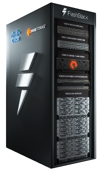
This document discusses the design principles that go into the FlashStackÔ solution, which is a validated Converged Infrastructure (CI) jointly developed by Cisco and Pure Storage. The solution is a predesigned, best-practice data center architecture with VMware vSphere built on the Cisco Unified Computing System (Cisco UCS), the Cisco Nexus® 9000 family of switches, Cisco MDS 9000 family of Fibre Channel switches and Pure Storage FlashArray//X R3 all flash array supporting either iSCSI or Fibre Channel storage access.
The solution architecture presents a robust infrastructure viable for a wide range of application workloads implemented as a Virtual Server Infrastructure (VSI).
In the current industry there is a trend for pre-engineered solutions which standardize the data center infrastructure, offering the business operational efficiencies, agility, and scale to address cloud, bi-modal IT, and their business. Their challenge is complexity, diverse application support, efficiency, and risk; all these are met by FlashStack with:
● Reduced complexity, automatable infrastructure and easily deployed resources
● Robust components capable of supporting high performance and high bandwidth virtualized applications
● Efficiency through optimization of network bandwidth and in-line storage compression with de-duplication
● Risk reduction at each level of the design with resiliency built into each touch point
Cisco and Pure Storage have partnered to deliver this Cisco Validated Design, which uses best of breed storage, server, and network components to serve as the foundation for virtualized workloads, enabling efficient architectural designs that can be quickly and confidently deployed.
In this document we will describe a reference architecture detailing a Virtual Server Infrastructure composed of Cisco Nexus switches, Cisco UCS Compute, Cisco MDS Multilayer Fabric Switches, and a Pure Storage FlashArray//X50 R3 delivering a VMware vSphere 7.0 hypervisor environment.
The audience for this document includes, but is not limited to; sales engineers, field consultants, professional services, IT managers, partner engineers, and customers who want to modernize their infrastructure to meet their business needs
This document discusses the design for FlashStack, implemented with either FC or iSCSI, centered around the Cisco UCS 6454 Fabric Interconnect and the Pure Storage FlashArray//X50 R3, delivering a Virtual Server Infrastructure on Cisco UCS B200 M5 Blade Servers, Cisco UCS C220 M5 Rack Servers, and Cisco C4200 Multi-Node Servers running VMware vSphere 7.0.
The deployment of these designs is detailed in their respective FlashStack Virtual Server Infrastructure Deployment Guides found here:
This version of the FlashStack VSI Design introduces the Pure Storage FlashArray//X50 R3 all-flash array along with Cisco UCS C4200 Module Rack Chassis and C125 M5 Servers featuring the AMD EPYC Family of CPUs. The design incorporates options for 40Gb iSCSi as well as 32Gb Fibre Channel, both delivered with new design options and features. Highlights for this design include:
● Pure Storage FlashArray//X50 R3
● VMware vSphere 7.0
● Cisco UCS Manager 4.1
● Cisco UCS C125 M5
● Cisco Intersight Orchestration
● Support for 32Gb FC SAN Switching in the Cisco Nexus 93180YC-FX switch
FlashStack provides a jointly supported solution by Cisco and Pure Storage. Bringing a carefully validated architecture built on superior compute, world class networking, and the leading innovations in all flash storage. The portfolio of validated offerings from FlashStack includes but is not limited to the following:
● Consistent performance: FlashStack provides higher, more consistent performance than disk-based solutions and delivers a converged infrastructure based on all-flash that provides non-disruptive upgrades and scalability.
● Cost savings: FlashStack uses less power, cooling, and data center space when compared to legacy disk/hybrid storage. It provides industry-leading storage data reduction and exceptional storage density.
● Simplicity: FlashStack requires low ongoing maintenance and reduces operational overhead. It also scales simply and smoothly in step with business requirements.
● Deployment choices: It is available as a custom-built single unit from FlashStack partners, but organizations can also deploy using equipment from multiple sources, including equipment they already own.
● Unique business model: The Pure Storage Evergreen Storage Model enables companies to keep their storage investments forever, which means no more forklift upgrades and no more downtime.
● Mission-critical resiliency: FlashStack offers best in class performance by providing active-active resiliency, no single point of failure, and non-disruptive operations, enabling organizations to maximize productivity.
● Support choices: Focused, high-quality single-number reach for FlashStack support is available from FlashStack Authorized Support Partners. Single-number support is also available directly from Cisco Systems as part of the Cisco Solution Support for Data Center offering. Support for FlashStack components is also available from Cisco, VMware, and Pure Storage individually and leverages TSANet for resolution of support queries between vendors.
This section provides a technical overview of the compute, network, storage, and management components in this solution.
Cisco Unified Computing System
The Cisco Unified Computing System™ (Cisco UCS) is a next-generation data center platform that integrates computing, networking, storage access, and virtualization resources into a cohesive system designed to reduce total cost of ownership and increase business agility. The system integrates a low-latency, lossless 10-100 Gigabit Ethernet unified network fabric with enterprise-class, x86-architecture servers. The system is an integrated, scalable, multi-chassis platform with a unified management domain for managing all resources.
The Cisco Unified Computing System consists of the following subsystems:
● Compute - The compute piece of the system incorporates servers based on latest AMD and Intel x86 processors. Servers are available in blade and rack form factor, managed by Cisco UCS Manager.
● Network - The integrated network fabric in the system provides a low-latency, lossless, 10/25/40/100 Gbps Ethernet fabric. Networks for LAN, SAN and management access are consolidated within the fabric. The unified fabric uses the innovative Single Connect technology to lowers costs by reducing the number of network adapters, switches, and cables. This in turn lowers the power and cooling needs of the system.
● Storage access - Cisco UCS system provides consolidated access to both SAN storage and Network Attached Storage over the unified fabric. This provides customers with storage choices and investment protection. The use of Policies, Pools, and Profiles allows for simplified storage connectivity management
● Management - The system uniquely integrates compute, network, and storage access subsystems, enabling it to be managed as a single entity through Cisco UCS Manager software. Cisco UCS Manager increases IT staff productivity by enabling storage, network, and server administrators to collaborate on Service Profiles that define the desired server configurations
Cisco Unified Compute System has revolutionized the way servers are managed in data-center and provides several unique differentiators that are outlined below:
● Embedded Management — Servers in Cisco UCS are managed by embedded software in the Fabric Interconnects.
● Unified Fabric — Cisco UCS uses a wire-once architecture, where a single Ethernet cable is used from the FI from the server chassis for LAN, SAN, and management traffic. Adding compute capacity does not require additional connections. This converged I/O reduces overall capital and operational expenses.
● Auto Discovery — The server discovery process is automatic when a blade is inserted into a chassis or a rack server is connected to the Fabric Interconnect
● Policy Based Resource Classification — Once a compute resource is discovered, it can be automatically classified to a resource pool based on configured policies.
● Combined Rack and Blade Server Management — Cisco UCS Manager is hardware form factor agnostic and can manage both blade and rack servers under the same management domain.
● Model based Management Architecture — Cisco UCS Manager architecture and management database is model based. An open XML API is provided to operate on the management model which enables easy and scalable integration of Cisco UCS Manager with other management systems.
● Policies, Pools, and Templates — The management approach in Cisco UCS Manager is based on defining policies, pools, and templates. This enables a straightforward approach in managing compute, network and storage resources while decreasing the opportunities for misconfigurations
● Policy Resolution — In Cisco UCS Manager, a tree structure of organizational unit hierarchy can be created that mimics the real-life tenants and/or organization relationships. Various policies, pools and templates can be defined at different levels of organization hierarchy.
● Service Profiles and Stateless Computing — A service profile is a logical representation of a server, carrying its various identities and policies. This logical server can be assigned to any physical compute resource that meets the resource requirements. Stateless computing enables procurement of a server within minutes, which used to take days in legacy server management systems.
● Built-in Multi-Tenancy Support — The combination of a profiles-based approach using policies, pools and templates and policy resolution with organizational hierarchy to manage compute resources makes Cisco UCS Manager suitable for multi-tenant environments.
Cisco UCS Manager (UCSM) provides unified, integrated management for all software and hardware components in Cisco UCS. Using Cisco Single Connect technology, it manages, controls, and administers multiple chassis for thousands of virtual machines. Administrators use the software to manage the entire Cisco Unified Computing System as a single logical entity through an intuitive graphical user interface (GUI), a command-line interface (CLI), or a through a robust application programming interface (API).
Cisco UCS Manager is embedded into the Cisco UCS Fabric Interconnects and provides a unified management interface that integrates server, network, and storage. Cisco UCS Manger performs auto-discovery to detect inventory, manage, and provision system components that are added or changed. It offers a comprehensive set of XML API for third party integration, exposes thousands of integration points, and facilitates custom development for automation, orchestration, and to achieve new levels of system visibility and control.
Cisco UCS Fabric Interconnects
The Cisco UCS Fabric Interconnects (FIs) provide a single point for connectivity and management for the entire Cisco UCS system. Typically deployed as an active-active pair, the system’s fabric interconnects integrate all components into a single, highly-available management domain controlled by the Cisco UCS Manager. Cisco UCS FIs provide a single unified fabric for the system, with low-latency, lossless, cut-through switching that supports LAN, SAN and management traffic using a single set of cables.
The 4th generation (6400) fabric delivers options for both high workload density, as well as high port count, with both supporting either Cisco UCS B-Series blade servers, or Cisco UCS C-Series rack mount servers. The Fabric Interconnect model featured in this design is:
● Cisco UCS 6454 Fabric Interconnect is a 54 port 1/10/25/40/100GbE/FCoE switch, supporting 8/16/32Gbps FC ports and up to 3.82Tbps throughput. This model is aimed at higher port count environments that can be configured with 32Gbps FC connectivity to Cisco MDS switches or FC direct attached storage.

Table 1 lists the comparison of the port capabilities of the different Fabric Interconnect models.
Table 1. Cisco UCS 6200 and 6300 Series Fabric Interconnects
| Features |
6332 |
6332-16UP |
6454 |
65108 |
| Max 10G ports |
96* + 2** |
72* + 16 |
48 |
96 |
| Max 25G ports |
N/A |
N/A |
48 |
96 |
| Max 40G ports |
32 |
24 |
6 |
12 |
| Max 100G ports |
N/A |
N/A |
6 |
12 |
| Max unified ports |
N/A |
16 |
8 |
16 |
| Max FC ports |
N/A |
16x 4/8/16G |
8x 8/16/32G |
16x 8/16/32G |
* Using 40G to 4x10G breakout cables ** Requires QSA module
The Cisco UCS Fabric extenders (FEX) or I/O Modules (IOMs) multiplex and forwards all traffic from servers in a blade server chassis to a pair of Cisco UCS Fabric Interconnects over a 10Gbps or 40Gbps unified fabric links. All traffic, including traffic between servers on the same chassis, or between virtual machines on the same server, is forwarded to the parent fabric interconnect where Cisco UCS Manager runs, managing the profiles and polices for the servers. FEX technology was developed by Cisco. Up to two FEXs can be deployed in a chassis.
For more information about the benefits of FEX, see: http://www.cisco.com/c/en/us/solutions/data-center-virtualization/fabric-extender-technology-fex-technology/index.html
Cisco UCS 5108 Blade Server Chassis
The Cisco UCS 5108 Blade Server Chassis is a fundamental building block of the Cisco Unified Computing System, delivering a scalable and flexible blade server architecture. The Cisco UCS blade server chassis uses an innovative unified fabric with fabric-extender technology to lower TCO by reducing the number of network interface cards (NICs), host bus adapters (HBAs), switches, and cables that need to be managed, cooled, and powered. It is a 6-RU chassis that can house up to 8 x half-width or 4 x full-width Cisco UCS B-series blade servers. A passive mid-plane provides up to 80Gbps of I/O bandwidth per server slot and up to 160Gbps for two slots (full-width). The rear of the chassis contains two I/O bays to house a pair of Cisco UCS 2000 Series Fabric Extenders to enable uplink connectivity to FIs for both redundancy and bandwidth aggregation.
The Cisco UCS Virtual Interface Card (VIC) 1400 Series extends the network fabric directly to both servers and virtual machines so that a single connectivity mechanism can be used to connect both physical and virtual servers with the same level of visibility and control. Cisco VICs provide complete programmability of the Cisco UCS I/O infrastructure, with the number and type of I/O interfaces configurable on demand with a zero-touch model. The VIC presents virtual NICs (vNICs) as well as virtual HBAs (vHBAs) from the same adapter, according to their provisioning specifications within UCSM.
Figure 1. Cisco UCS C125 M5 Rack Servers in the Cisco UCS C4200 Series Rack Server Chassis
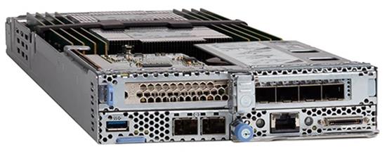
The Cisco UCS C4200 chassis extends the capabilities of the Cisco UCS portfolio in a 2-Rack-Unit (2RU) form factor supporting up to four Cisco UCS C125 M5 Rack Server Nodes. The latest update includes support for AMD EPYC 2 (Rome) 7002 processors validated in this design. The AMD EPYC 2 processors have higher core density (up to 64 cores) and higher performance with an enhanced AMD Zen 2 core design. The AMD EPYC 7001 processors will continue to be offered for flexibility of customer choice. Both CPU types deliver significant performance and efficiency gains in a compact form factor that will improve your application performance while saving space. The C4200 and the C125 M5 nodes deliver outstanding levels of capability and performance in a highly compact package, with:
● AMD EPYC 7002 (Rome) series processors, with up to 64 cores per socket, AMD EPYC 7001 (Naples) series processors with up to 32 cores per socket.
● Up to 1 TB of DRAM using sixteen 64-GB DDR4 DIMMs for 2-socket CPU configuration (eight DIMMs/memory channels per CPU)
● 3200 MHz 16G/32G/64G DIMMs for AMD EPYC 7002 (Rome) CPUs and 2666 MHz 16G/32G/64G DIMMs for AMD EPYC 7001 (Naples) CPUs
● Optional dual SD cards or M.2 modular storage for increased storage or boot drive capacity
● Support for Cisco’s fourth-generation PCIe Virtual Interface Card (VIC) 1455 offering up to 100 Gbps of I/O throughput with Cisco UCS 6454 FI
For more information about the Cisco UCS C125 M5 Rack Server Nodes in the Cisco UCS C4200 Rack Server Chassis, see: https://www.cisco.com/c/en/us/products/collateral/servers-unified-computing/ucs-c4200-series-rack-server-chassis/datasheet-c78-740839.html.
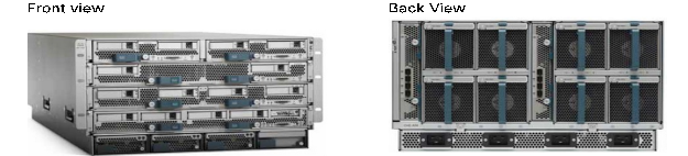
Figure 2. Cisco UCS B200 M5 Servers
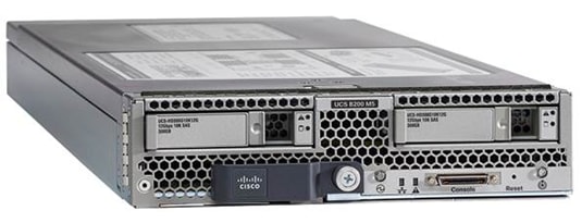
The enterprise-class Cisco UCS B200 M5 Blade Server extends the Cisco UCS portfolio in a half-width blade form-factor. This M5 server uses the latest Intel® Xeon® Scalable processors with up to 28 cores per processor, 3TB of RAM (using 24 x128GB DIMMs), 2 drives (SSD, HDD or NVMe), 2 GPUs and 80Gbps of total I/O to each server. It supports the Cisco VIC 1440 adapter to provide 40Gb FCoE connectivity to the unified fabric.
It features:
● 2nd Gen Intel® Xeon® Scalable and Intel® Xeon® Scalable processors with up to 28 cores per socket
● Up to two GPUs
● Two Small-Form-Factor (SFF) drive slots
● Up to two Secure Digital (SD) cards or M.2 SATA drives
● Up to 80 Gbps of I/O throughput with Cisco UCS 6454 FI
For more information about the Cisco UCS B200 M5 Blade Servers, see: http://www.cisco.com/c/en/us/products/collateral/servers-unified-computing/ucs-b-series-blade-servers/datasheet-c78-739296.html.
Figure 3. Cisco UCS C220 M5 Servers
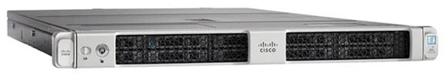
The enterprise-class Cisco UCS C220 M5 Rack Server extends the Cisco UCS portfolio in a 1RU rack server. This M5 server uses the latest Intel® Xeon® Scalable processors with up to 28 cores per processor, 3TB of RAM (using 24 x128GB DIMMs), 10 drives (SSD, HDD or NVMe), 2 GPUs and up to 200Gbps of unified I/0 to the server. It supports a variety of other PCIe options detailed in the spec sheet. https://www.cisco.com/c/dam/en/us/products/collateral/servers-unified-computing/ucs-c-series-rack-servers/c220m5-sff-specsheet.pdf
It features:
● 2nd Gen Intel® Xeon® Scalable and Intel® Xeon® Scalable processors, 2-socket
● Up to 24 DDR4 DIMMs for improved performance with up to 12 DIMM slots ready for Intel Optane™ DC Persistent Memory
● Up to 10 Small-Form-Factor (SFF) 2.5-inch drives or 4 Large-Form-Factor (LFF) 3.5-inch drives (77 TB storage capacity with all NVMe PCIe SSDs)
● Support for 12-Gbps SAS modular RAID controller in a dedicated slot, leaving the remaining PCIe Generation 3.0 slots available for other expansion cards
● Modular LAN-On-Motherboard (mLOM) slot that can be used to install a Cisco UCS Virtual Interface Card (VIC) without consuming a PCIe slot
● Dual embedded Intel x550 10GBASE-T LAN-On-Motherboard (LOM) ports
● Up to 100 Gbps of I/O throughput with Cisco UCS 6454 FI
For more information about the Cisco UCS B200 M5 Blade Servers, see: https://www.cisco.com/c/en/us/products/collateral/servers-unified-computing/ucs-c-series-rack-servers/datasheet-c78-739281.html.
Figure 4. Cisco Nexus 9000 Series Switch
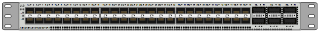
The Cisco Nexus 9000 Series Switches offer both modular and fixed 10/40/100 Gigabit Ethernet switch configurations with scalability up to 60 Tbps of non-blocking performance with less than five-microsecond latency, wire speed VXLAN gateway, bridging, and routing support.
Supporting either Cisco ACI or NX-OS, the Nexus delivers a powerful 40/100Gbps platform offering up to 7.2 TBps of bandwidth in a compact 1RU TOR switch. The Nexus featured in this design is the Nexus 93180YC-FX implemented in NX-OS standalone mode.
Figure 5. Cisco MDS 9000 Series Switch
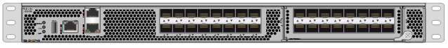
The Cisco MDS 9000 family of multilayer switches give a diverse range of storage networking platforms, allowing you to build a highly scalable storage network with multiple layers of network and storage management intelligence. Fixed and modular models implement 4-32Gbps FC, 10-40Gbps FCoE/FCIP, and up to 48 TBps of switching bandwidth.
The MDS 9132T Fibre Channel Switch is featured in this design as the option for the Fibre Channel network
This 1RU switch offers a variable port count, support for NVME over FC, and SAN analytics.
Cisco Intersight
Cisco Intersight gives IT operations management to claimed devices across differing sites, presenting these devices within a unified dashboard. The adaptive management of Intersight provides visibility and alerts to firmware management, showing compliance across managed UCS domains, as well as proactive alerts for upgrade recommendations. Integration with Cisco TAC allows the automated generation and upload of tech support files from the customer.
The Pure Storage FlashArray family delivers purpose-built, software-defined all-flash power and reliability for businesses of every size. FlashArray is all-flash enterprise storage that is up to 10X faster, more space and power efficient, more reliable, and far simpler than other available solutions. Critically, FlashArray also costs less, with a TCO that's typically 50% lower than traditional performance disk arrays.
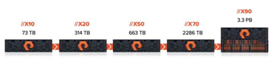
At the top of the FlashArray line is FlashArray//X – the first mainstream, 100% NVMe, enterprise-class all-flash array. //X represents a higher performance tier for mission-critical databases, top-of-rack flash deployments, and Tier 1 application consolidation. //X, at 1PB in 3U, with hundred-microsecond range latency and GBs of bandwidth, delivers an unprecedented level of performance density that makes possible previously unattainable levels of consolidation.
FlashArray//X is ideal for cost-effective consolidation of everything on flash. Whether accelerating a single database, scaling virtual desktop environments, or powering an all-flash cloud, there is an //X model that fits your needs.
At the heart of every FlashArray is Purity Operating Environment software. Purity//FA implements advanced data reduction, storage management, and flash management features, enabling organizations to enjoy Tier 1 data services for all workloads, proven 99.9999% availability over two years (inclusive of maintenance and generational upgrades), completely non-disruptive operations, 2X better data reduction versus alternative all-flash solutions, and – with FlashArray//X – the power and efficiency of DirectFlash™. Moreover, Purity includes enterprise-grade data security, comprehensive data protection options, and complete business continuity via ActiveCluster multi-site stretch cluster. All these features are included with every array.
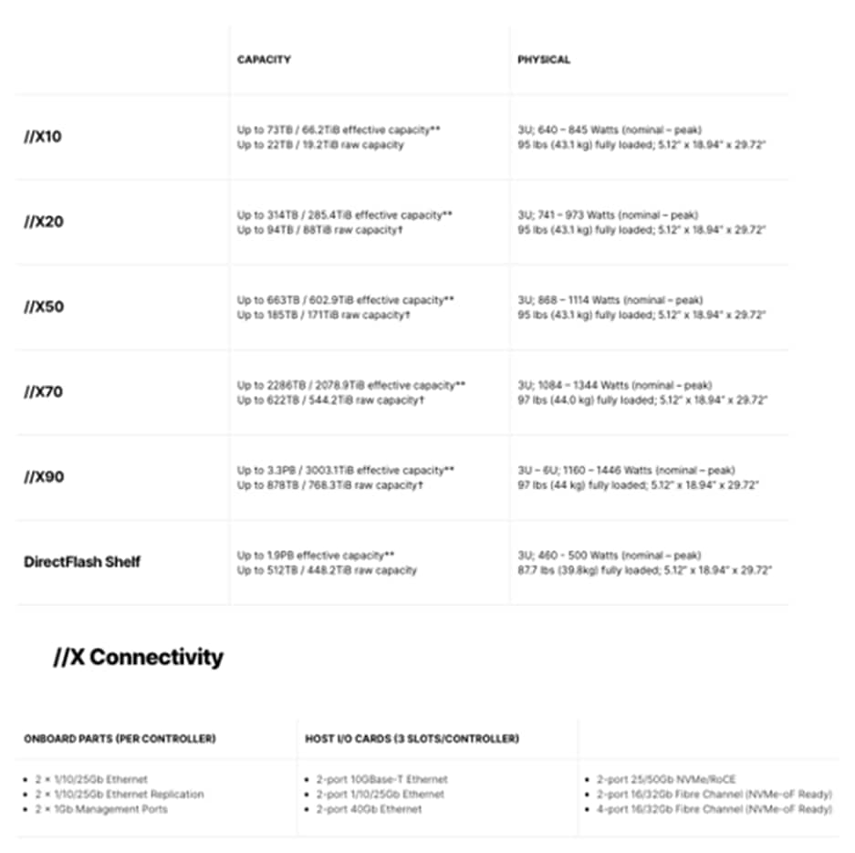
** Effective capacity assumes HA, RAID, and metadata overhead, GB-to-GiB conversion, and includes the benefit of data reduction with always-on inline deduplication, compression, and pattern removal. Average data reduction is calculated at 5-to-1 and does not include thin provisioning or snapshots.
† Array accepts Pure Storage DirectFlash Shelf and/or Pure Storage SAS-based expansion shelf.
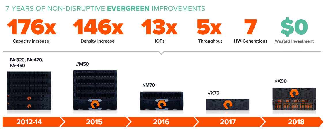
Customers can deploy storage once and enjoy a subscription to continuous innovation via Pure’s Evergreen Storage ownership model: expand and improve performance, capacity, density, and/or features for 10 years or more – all without downtime, performance impact, or data migrations. Pure has disrupted the industry’s 3-5-year rip-and-replace cycle by engineering compatibility for future technologies right into its products, notably with the NVMe-Ready Guarantee for //M and online upgrade from any //M to //X.
Pure1, our cloud-based management, analytics, and support platform, expands the self-managing, plug-n-play design of Pure all-flash arrays with the machine learning predictive analytics and continuous scanning of Pure1 Meta™ to enable an effortless, worry-free data platform.
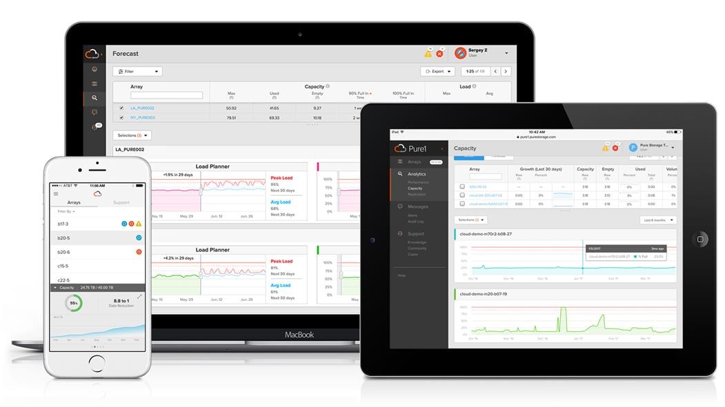
Pure1 Manage
In the Cloud IT operating model, installing, and deploying management software is an oxymoron: you simply login. Pure1 Manage is SaaS-based, allowing you to manage your array from any browser or from the Pure1 Mobile App – with nothing extra to purchase, deploy, or maintain. From a single dashboard you can manage all your arrays, with full visibility on the health and performance of your storage.
Pure1 Analyze
Pure1 Analyze delivers true performance forecasting – giving customers complete visibility into the performance and capacity needs of their arrays – now and in the future. Performance forecasting enables intelligent consolidation and unprecedented workload optimization.
Pure1 Support
Pure combines an ultra-proactive support team with the predictive intelligence of Pure1 Meta to deliver unrivaled support that’s a key component in our proven FlashArray 99.9999% availability. Customers are often surprised and delighted when we fix issues they did not even know existed.
Pure1 META
The foundation of Pure1 services, Pure1 Meta is global intelligence built from a massive collection of storage array health and performance data. By continuously scanning call-home telemetry from Pure’s installed base, Pure1 Meta uses machine learning predictive analytics to help resolve potential issues and optimize workloads. The result is both a white glove customer support experience and breakthrough capabilities like accurate performance forecasting.
Meta is always expanding and refining what it knows about array performance and health, moving the Data Platform toward a future of self-driving storage.
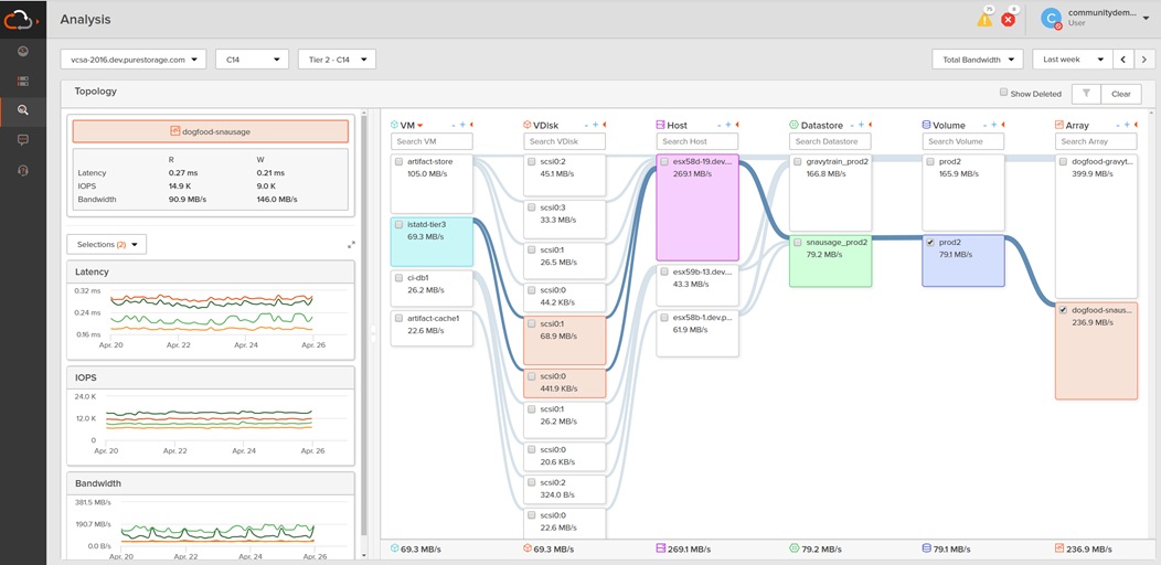
Pure1 Analyze – VM Analytics
With VM Analytics, customers get full-stack visibility from storage all the way up to a VM, there are four basic functions of VM Analytics – you can change which metric is displayed on the node, you can highlight everything that’s connected to the node, you can filter what you’re seeing, and you can graph the metrics from the node. These are simple actions, but they make a highly versatile product.
At the very core of the product is the topology map which shows Disks, VMs, Hosts, Datastores, Volumes, and Arrays in the cluster that’s selected. By clicking on any of the nodes, you can easily visualize what’s connected to that object. For example, you can select a VM to see which volume or array it’s on. Or you could go the other way and see which VMs are living on a volume by selecting the volume.
With visibility throughout the stack, you have insight into the latency, bandwidth, and IOPs of your workflows – and the data points you need to quickly resolve issues and pinpoint latency problems or other bottlenecks.
VMware vSphere vCenter Server
VMware vCenter Server provides unified management of all hosts and VMs from a single console and aggregates performance monitoring of clusters, hosts, and VMs. VMware vCenter Server gives administrators a deep insight into the status and configuration of compute clusters, hosts, VMs, storage, the guest OS, and other critical components of a virtual infrastructure. VMware vCenter manages the rich set of features available in a VMware vSphere environment.
VMware vSphere Client
The VMware vSphere Client is a cross-platform web application used to interact with the VMware vCenter server — for managing clusters, hosts, and virtual machines in data centers. The Web Client provides full vSphere client functionality including capabilities for configuring hosts, clusters, networks, datastores, or datastore clusters.
The Pure Storage vSphere HTML Client Plugin extends the vSphere Client with capability for managing Pure Storage FlashArray volumes and snapshots in a vCenter context. The Plugin makes it possible to create, monitor, and manage VMware datastores based on FlashArray volumes (and related snapshots) completely from within the vSphere Client.
The Plugin also supports these actions:
● Opening a Purity GUI session in the vSphere Web Client
● Assigning datastores membership in Pure Storage protection groups
● Creating a FlashArray host group for a vSphere cluster
● Full ActiveCluster/Pod Datastore Provisioning
● Support for ActiveDR
● Initiating or scheduling a space reclamation run on a FlashArray
● Configuring role-based access control for vSphere and FlashArray users
● Working with FlashArray virtual volumes (vVols)
● Authenticating to Pure1 for busy meter and intelligent provisioning.
● For more information about the features released for the VMware vSphere HTML Client Plugin, see the Release Notes:
The FlashStack Solutions Design implements a Virtual Server Infrastructure that is scalable, reliable, and redundant, using the best practices of Cisco and Pure Storage. This section will cover the architecture used in the solution.
The FlashStack datacenter is intended to provide a Virtual Server Infrastructure that addresses the primary needs of hosting virtual machines. This design assumes an existing management, security, and routing infrastructure to provide necessary connectivity. This includes but is not limited to the following:
● Out-of-Band management network
● A terminal server for console access
● Layer 3 connectivity to adjacent enterprise network and/or the Internet
● DNS and NTP services
Each rack server in the design is redundantly connected to the managing fabric interconnects with at least one port to each FI. Ethernet traffic from the upstream network and Fibre Channel frames coming from the FlashArray are converged within the fabric interconnect to be both Ethernet and Fibre Channel over Ethernet and transmitted to the UCS server.
These connections from the Cisco UCS 6454 Fabric Interconnect to the 2408XP IOM hosted within the chassis are shown in Figure 6.
Figure 6. Compute Connectivity
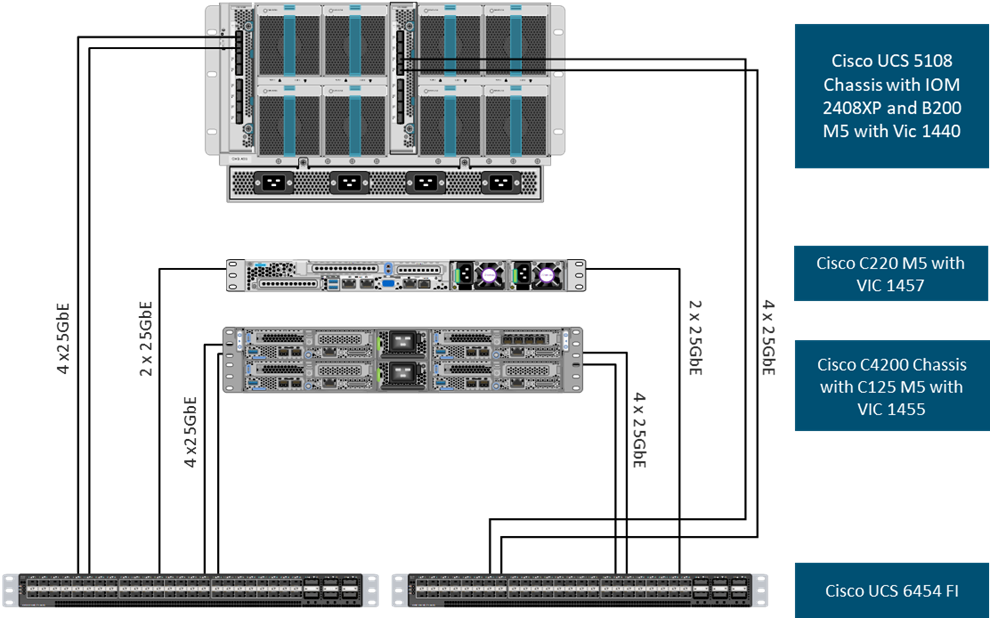
![]() The 2408XP IOM are shown with 4x25Gbps ports to deliver an aggregate of 100Gbps to the chassis, full population of the 2408XP IOM can support 8x25Gps ports, allowing for an aggregate of 200Gbps to the chassis.
The 2408XP IOM are shown with 4x25Gbps ports to deliver an aggregate of 100Gbps to the chassis, full population of the 2408XP IOM can support 8x25Gps ports, allowing for an aggregate of 200Gbps to the chassis.
![]() The Cisco UCS C4200 Chassis is shown with 2x25Gbps ports per C125 rack server node to deliver an aggregate of 50Gbps to the server node, full population of the VIC1455 can support 4x25Gps ports, allowing for an aggregate of 100Gbps to the server node.
The Cisco UCS C4200 Chassis is shown with 2x25Gbps ports per C125 rack server node to deliver an aggregate of 50Gbps to the server node, full population of the VIC1455 can support 4x25Gps ports, allowing for an aggregate of 100Gbps to the server node.
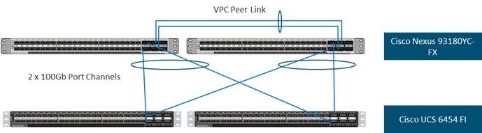
The Layer 2 network connection to each Fabric Interconnect is implemented as Virtual Port Channels (vPC) from the upstream Nexus Switches. In the switching environment, the vPC provides the following benefits:
● Allows a single device to use a Port Channel across two upstream devices
● Eliminates Spanning Tree Protocol blocked ports and use all available uplink bandwidth
● Provides a loop-free topology
● Provides fast convergence if either one of the physical links or a device fails
● Helps ensure high availability of the network
The upstream network switches can connect to the Cisco UCS 6454 Fabric Interconnects using 10G, 25G, 40G, or 100G port speeds. In this design, both the 25GB and 100G port options were tested for the virtual port channels. In the iSCSI design, this would also transport the storage traffic between the Cisco UCS servers and the FlashArray//X R3
Figure 7. Network Connectivity
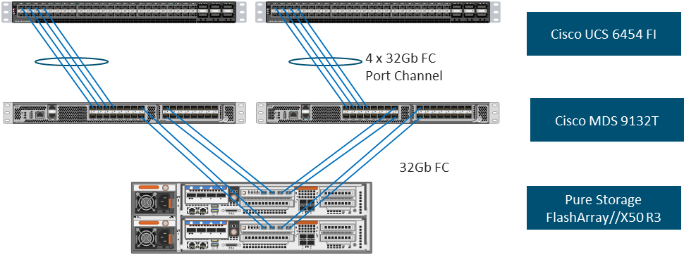
Fibre Channel Storage Connectivity
The Pure Storage FlashArray//X50 R3 platform is connected through both MDS 9132Ts to their respective Fabric Interconnects in a traditional air-gapped A/B fabric design. The Fabric Interconnects are configured in N-Port Virtualization (NPV) mode, known as FC end host mode in UCSM. The MDS has N-Port ID Virtualization (NPIV) enabled. This allows F-port channels to be used between the Fabric Interconnect and the MDS, providing the following benefits:
● Increased aggregate bandwidth between the fabric interconnect and the MDS
● Load balancing across the FC uplinks
● High availability in the event of a failure of one or more uplinks
Figure 8. Fibre Channel Storage Connectivity
End-to-End Physical Connectivity
The FC end-to-end path in this design is a traditional air-gapped fabric with identical data path through each fabric as listed below:
● Each Cisco UCS Server is equipped with a Cisco UCS VIC 1400 Series adapter.
● In the Cisco B200 M5 server, a Cisco UCS VIC 1440 provides 2x10Gbps to IOM A and 2x10Gbps to IOM B via the Cisco UCS Chassis 5108 chassis backplane.
● In the Cisco UCS C220 M5 server, a VIC 1457 is used with 2x 25Gbps connections to FI-A and 2x5Gbps FI-B for a total of 4x25Gbps of uplink bandwidth.
● Each IOM is connected to its respective Cisco UCS 6454 Fabric Interconnect using a port-channel for 4-8 links.
● Each Cisco UCS 6454 FI connects to the MDS 9132T for the respective SAN fabric using an F-Port channel.
● The Pure FlashArray//X50 R3 is connected to both MDS 9132T switches to provide redundant paths through both fabrics.
Figure 9. FC End-to-End Data Path
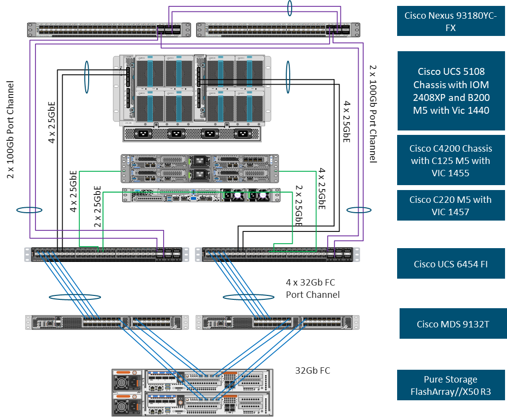
The components of this integrated architecture shown in Figure 9 are:
● Cisco Nexus 93180YC-FX – 10/25/40/100Gb capable, LAN connectivity to the Cisco UCS compute resources.
● Cisco UCS 6454 Fabric Interconnect – Unified management of Cisco UCS compute, and the compute’s access to storage and networks.
● Cisco UCS B200 M5 – High powered blade server, optimized for virtual computing.
● Cisco UCS C125 M5 – High powered rack server node, optimized for virtual computing.
● Cisco UCS C220 M5 – High powered rack server, optimized for virtual computing.
● Cisco MDS 9132T – 32Gbps Fibre Channel connectivity within the architecture, as well as interfacing to resources present in an existing data center.
● Pure Storage FlashArray//X50 R3.
Cisco Nexus 93180YC-FX SAN Switching
Beginning with Cisco NX-OS Release 9.3(3), the Cisco Nexus 93180YC-FX switch supports SAN Switching, allowing a single switch to provide both SAN and LAN switching. With Cisco NX-OS Release 9.3(5), validated in this design, the needed SAN switching features enhanced device alias and smart zoning are supported. These features allow Cisco Data Center Network Manager to both monitor the Cisco Nexus 93180YC-FX and to configure device aliases, zones, and zonesets. These features also allow a Cisco Nexus 93180YC-FX to be connected to an MDS switch or fabric and for device aliases and smart zones to be distributed between all switches in the fabric. Cisco Nexus 93180YC-FX SAN switching is covered in the appendix of the Deployment Guide for this solution. For more information on Cisco Nexus 93180YC-FX SAN Switching, please refer to https://www.cisco.com/c/en/us/td/docs/switches/datacenter/nexus9000/sw/93x/san_switching/configuration/guide/b-cisco-nexus-9000-nx-os-san-switching-configuration-guide-933.html.
The iSCSI end-to-end data path in this design leverages the Cisco Nexus 93180YX-FX networking switches to carry storage traffic as detailed below:
● Each Cisco UCS Server is equipped with a Cisco UCS VIC 1400 Series adapter.
● In the Cisco B200 M5 server, a Cisco UCS VIC 1440 provides 20Gb to IOM A and 20Gbps to IOM B via the Cisco UCS Chassis 5108 chassis backplane.
● In the Cisco UCS C220 M5 server, a Cisco UCS VIC 1457 is used with a 4x 10/25Gbps connection.
● In the Cisco UCS C125 M5 server is this the Cisco UCS VIC 1455 with 4x 10/25Gbps connection.
● Each IOM is connected to its respective Cisco UCS 6454 Fabric Interconnect using a port-channel for 4-8 links.
● Each Cisco UCS C-Series Server is attached via a 25Gb port to each Cisco UCS 6454 FI.
● Each Cisco UCS 6454 FI connects to the Cisco Nexus 93180YC-FX via 2x 100Gbps virtual port channels.
● Each controller on the Pure FlashArray//X50 R3 is connected to each Cisco Nexus 93180YC-FX switch via 2x 40Gbps connections to provide redundant paths.
Figure 10. iSCSI End-to-End Data Path
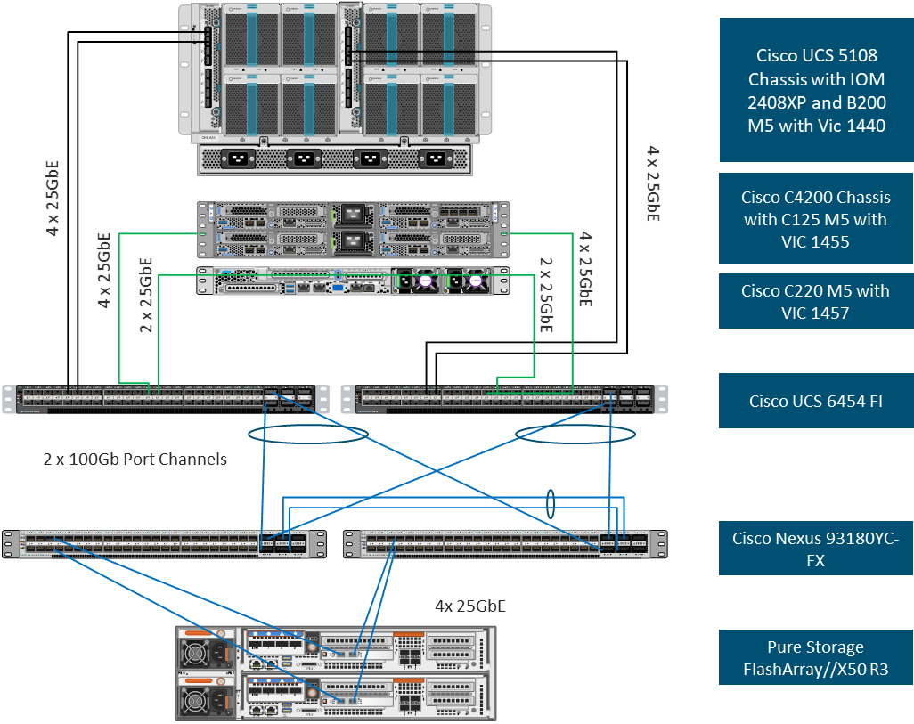
The components of this integrated architecture shown in Figure 10 are:
● Cisco Nexus 93180YC-FX – 10/25/40/100Gb capable, LAN connectivity to the Cisco UCS compute resources and Pure Storage resource.
● Cisco UCS 6454 Fabric Interconnect – Unified management of Cisco UCS compute, and the compute’s access to storage and networks.
● Cisco UCS B200 M5 – High powered blade server, optimized for virtual computing.
● Cisco UCS C125 M5 – High powered rack server node, optimized for virtual computing.
● Cisco UCS C220 M5 – High powered rack server, optimized for virtual computing.
● Pure Storage FlashArray//X50 R3.
![]() The Pure Storage FlashArray//X50 R3 supports the addition of 40Gb Ethernet cards which can be used in this design.
The Pure Storage FlashArray//X50 R3 supports the addition of 40Gb Ethernet cards which can be used in this design.
![]() Only the Fibre Channel and Best Effort QoS System Classes are enabled in this FlashStack implementation. The Cisco UCS and Cisco Nexus switches are intentionally configured this way so that all IP traffic within the FlashStack will be treated as Best Effort. Enabling the other QoS System Classes without having a comprehensive, end-to-end QoS setup in place can cause difficult to troubleshoot issues. Note also that if the Platinum class is enabled, the MTU must be set to 9216 to use Jumbo Frames in that class.
Only the Fibre Channel and Best Effort QoS System Classes are enabled in this FlashStack implementation. The Cisco UCS and Cisco Nexus switches are intentionally configured this way so that all IP traffic within the FlashStack will be treated as Best Effort. Enabling the other QoS System Classes without having a comprehensive, end-to-end QoS setup in place can cause difficult to troubleshoot issues. Note also that if the Platinum class is enabled, the MTU must be set to 9216 to use Jumbo Frames in that class.
Compute and Virtualization Layer Design
The following are the compute options used in this design.
Cisco UCS B-Series
The Cisco UCS B200 M5 servers were selected for this converged infrastructure. Supporting up to 3TB of memory in a half width blade format, these Cisco UCS servers are ideal virtualization hosts. These servers are configured in the design with:
● Diskless SAN boot – Persistent operating system installation, independent of the physical blade for true stateless computing.
● Cisco VIC 1440 – Dual-port 40Gbps capable of up to 256 Express (PCIe) virtual adapters.
Cisco UCS C2X0 Series
The Cisco UCS C220 M5 servers were selected for this converged infrastructure. Supporting up to 3TB of memory in a 1RU rack mount format, these UCS servers are ideal virtualization hosts. These servers are configured in the design with:
● Diskless SAN boot – Persistent operating system installation, independent of the physical blade for true stateless computing.
● Cisco VIC 1457 – Quad-port 10/25Gpbs capable of up to 256 Express (PCIe) virtual adapters.
Cisco UCS C125 Series
The Cisco UCS C125 M5 servers were selected for this converged infrastructure. Supporting up to 1TB of memory in half width node format in the Cisco UCS C4200 2 RU/4 Node chassis. These Cisco UCS servers are ideal virtualization hosts. These servers are configured in the design with:
● Diskless SAN boot – Persistent operating system installation, independent of the physical blade for true stateless computing.
● Cisco VIC 1455 – Quad-port 10/25Gpbs capable of up to 256 Express (PCIe) virtual adapters.
Cisco UCS Service Profiles and Cisco UCS Service Profile Templates
Cisco UCS Service Profiles (SP) were configured with identity information pulled from pools (WWPN, MAC, UUID, and so on) as well as policies covering firmware to power control options. These SP are provisioned from Cisco UCS Service Profile Templates that allow rapid creation, as well as guaranteed consistency of the hosts at the Cisco UCS hardware layer.
Virtual Network Interface cards are created as virtual adapters from the Cisco UCS VICs to present the installed operating system. vNIC Templates provide a repeatable, reusable, and adjustable sub-component of the SP template for handling these vNICs. These vNICs templates were adjusted with the options for:
● Fabric association or failover between fabrics
● VLANs that should be carried
● Native VLAN specification
● VLAN and setting consistency with another vNIC template
● vNIC MTU
● MAC Pool specifications
This design is implemented using vSphere 7.0 for the vCenter Server and ESXi version. This design will leverage VMware Virtual Volumes (vVols) for storage integration.
Virtual Networking Configuration
The virtual networking configuration utilizes the Cisco UCS VIC adapter to present multiple adapters too ESXi as shown in Figure 11.
Figure 11. Virtual Networking Configuration
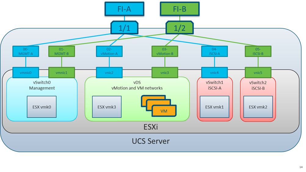
Adapters are created in pairs to provide redundancy to the vSwitches. One pair is created for management and one pair for application data and vmotion. In the Fibre Channel design, a pair of vHBAs will be created. In the iSCSI design an additional pair of vNICs will be created. VMware vDS (virtual distributed switches) are configured for vMotion and for Application traffic, with iSCSI traffic carried within standard vSwitches.
VMware Virtual Volumes (vVols), first introduced in VMware vSphere version 6.0, is a storage technology that provides policy-based, granular storage configuration and control of virtual machines (VMs). Through API-based interaction with underlying storage, VMware administrators can maintain storage configuration compliance using only native VMware interfaces.
Version 5.x of Purity//FA software introduced support for FlashArray-based vSphere Virtual Volumes (vVols). The accompanying FlashArray Plugin for the vSphere HTML Client (the Plugin) makes it possible to create, manage, and use vVols that are based on FlashArray volumes from within the vSphere Client.
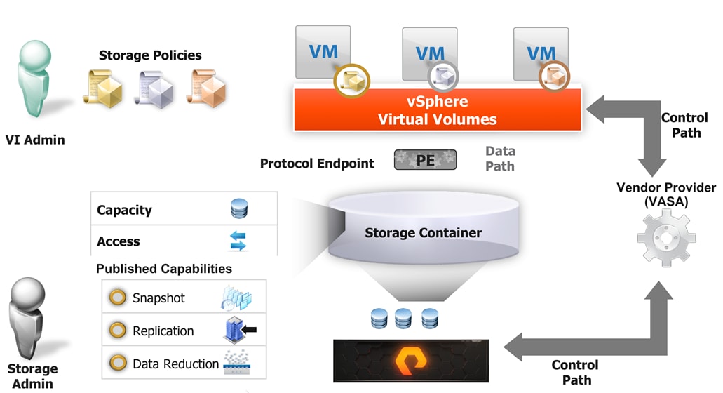
To start using vVols with the Pure Storage FlashArray the Array’s Storage Providers much be registered in vCenter Server, the Protocol Endpoint is then connected to the Host Group, and finally the vVol Datastore is created.
Register the FlashArray’s Storage Providers
The two main methods to register the Storage Providers is to manually add them in vCenter Server or to use the Pure Storage vSphere Web Client Plugin to register the storage provider for the given FlashArray. Pure Storage recommends using the Plugin to register the FlashArray’s Storage Providers.
Connect Protocol Endpoint to Host Group/s
Users will need to connect the protocol endpoint when manually creating the vVol Datastore in vCenter Server. This must be done via the FlashArray CLI. Should the Pure Storage Plugin be used, the plugin will automatically connect the PE to the host group that correlates to the ESXi Cluster that is used to create the vVol Datastore with the Plugin.
Mount the vVol Datastore
The vVol Datastore can be mounted manually or through the Pure Storage Plugin. When mounting the vVol Datastore it is highly recommended to mount it to all host in the ESXi Cluster.
Storage Policy Based Management (SPBM)
Storage Policies can be applied to vVols VMs that can automatically configure the volumes for the VM into FlashArray to be protected by FlashArray protection groups. Policies can be imported from existing FlashArray protection group policies or can be created in vCenter Server to match the requirements of existing Protection Groups.
For more information about the implementation of VMware Virtual Volumes with Pure Storage FlashArray, see:
The Cisco Nexus configuration covers the basic networking needs within the stack for Layer 2 to Layer 3 communication.
The following NX-OS features are implemented within the Nexus switches for the design:
● feature lacp – Allows for the utilization of Link Aggregation Control Protocol (802.3ad) by the port channels configured on the switch. Port channeling is a link aggregation technique offering link fault tolerance and traffic distribution (load balancing) for improved aggregate bandwidth across member ports.
● feature vpc – Allows for two Nexus switches to provide a cooperative port channel called a virtual Port Channel(vPC). vPCs present the Nexus switches as a single “logical” port channel to the connecting upstream or downstream device. Configured vPCs present the same fault tolerance and traffic distribution as a port-channel but allow these benefits to occur across links distributed between the two switches. Enablement of vPCs will require a connecting vPC Peer-Link between the two switches, as well as an out of band vPC keep alive to handle switch isolation scenarios.
Management Connectivity
Out-of-band management is handled by an independent switch that could be one currently in place in the customer’s environment. Each physical device had its management interface carried through this out-of-band switch, with in-band management carried as a differing VLAN within the solution for ESXi, vCenter Server and other virtual management components.
An MTU of 9216 was configured at all network levels to allow for the usage of jumbo frames as needed by the guest OS and application layer.
LUN Multipathing per HBA and Different Pathing Options
This design implements Single Initiator-Multi Target (SI-MT) zoning in conjunction with single vHBAs per fabric on the Cisco UCS infrastructure. This means that each vHBA within UCS will see multiple paths on their respective fabric to each LUN. Using this design requires the use of Cisco Smart Zoning within the MDS switches.
Different pathing options including Single Initiator-Single Target (SI-ST) are supported. This option would increase the administrative work and exposure to user error.
Balance your bandwidth and application needs, vSphere cluster utilization, and availability requirements when evaluating alternative pathing options to deploy this solution.
Smart Zoning
Zoning is set for Single Initiator/Multiple Target (SI-MT) to optimize traffic intended to be specific to the initiator (UCS host vHBA) and the targets (FlashArray controller ports). Using SI-MT zoning provides reduced administrative overhead versus configuring single initiator/single target zoning, and results in the same SAN switching efficiency when configured with Smart Zoning.
For more information about smart zoning, see the MDS zoning configuration guide: https://www.cisco.com/c/en/us/td/docs/switches/datacenter/mds9000/sw/8_x/config/fabric/cisco_mds9000_fabric_config_guide_8x/configuring_and_managing_zones.html#con_2017149
Cisco Nexus 9000 Series vPC Best Practices
The following Cisco Nexus 9000 design best practices and recommendations were used in this design.
vPC Peer Keepalive Link Considerations
It is recommended to have a dedicated layer 3 link for vPC peer keepalive, followed by out-of-band management interface (mgmt0) and lastly, routing the peer keepalive link over an existing Layer3 infrastructure between the existing vPC peers.
vPC peer keepalive link should not be routed over a vPC peer-link.
The out-of-band management network is used as the vPC peer keepalive link in this design.
Only vPC VLANs are allowed on the vPC peer-links. For deployments that require non-vPC VLAN traffic to be exchanged between vPC peer switches, deploy a separate Layer 2 link for this traffic.
Only required VLANs are allowed on the vPC peer links and member ports – prune all others to minimize internal resource consumption.
QoS Considerations
When using iSCSI for storage traffic, it may be necessary to prioritize the storage traffic over vMotion traffic. The deployment guide will include an example configuration but QoS settings should always include of comprehensive plan for the individual environment.
Cisco UCS Fabric Interconnect (FI) best practices
The following Cisco UCS Fabric Interconnect design best practices and recommendations were used in this design.
Ethernet end-host mode
This is the default switch mode for the Cisco UCS Fabric Interconnect.
In this mode the FI will only learn MAC addresses from devices connected on Server and Appliance ports.
In this mode the FI does not run spanning-tree and handles loop avoidance using a combination of Deja-Vu check and Reverse Path Forwarding (RFP).
Boot From SAN
When utilizing Cisco UCS Server technology, it is recommended to configure Boot from SAN and store the boot partitions on remote storage, this enabled architects and administrators to take full advantage of the stateless nature of service profiles for hardware flexibility across lifecycle management of server hardware generational changes, Operating Systems/Hypervisors, and overall portability of server identity. Boot from SAN also removes the need to populate local server storage creating more administrative overhead.
Pure Storage FlashArray Considerations
Make sure Each FlashArray Controller is connected to BOTH storage fabrics (A/B).
Within Purity it’s best practice to map Hosts to Host Groups and then Host Groups to Volumes, this ensures the Volume is presented on the same LUN ID to all hosts and allows for simplified management of ESXi Clusters across multiple nodes.
How big should a Volume be? With Purity, we remove the complexities of aggregates, RAID groups and so on. When managing storage, you just create a volume based on the size required, availability and performance are taken care of via RAID-HD and DirectFlash Software. As an administrator you can create 1 10TB volume or 10 1TB Volumes and their performance/availability will be the same, so instead of creating volumes for availability or performance you can think about recoverability, manageability, and administrative considerations. Like what data do I want to present to this application or what data do I want to store together so I can replicate it to another site/system/cloud…
Port Connectivity
10/25/40GbE connectivity support – while both 10 and 25 Gbps is provided via 2 onboard NICs on each FlashArray controller if any more interfaces are required or if 40GbE connectivity is also required then make sure there is provision for additional NICs have been included in the original FlashArray BOM.
16/32Gb Fiber Channel support (N-2 support) – Pure Storage offer up to 32Gb FC support on the latest FlashArray//X series arrays. Always make sure the correct number of HBAs and the speed of SFPs are included in the original FlashArray BOM.
Oversubscription
To reduce the impact of an outage or maintenance scheduled downtime it Is good practice when designing fabrics to provide oversubscription of bandwidth, this enables a similar performance profile during component failure and protects workloads from being impacted by a reduced number of paths during a component failure or maintenance event. Oversubscription can be achieved by increasing the number of physically cabled connections between storage and compute. These connections can then be utilized to deliver performance and reduced latency to the underlying workloads running on the solution.
Topology
When configuring your SAN, it’s important to remember that the more hops you have, the more latency you will see. For best performance, the ideal topology is a “Flat Fabric” where the FlashArray is only one hop away from any applications being hosted on it. For iSCSI, we recommend that you do not add routing to your storage LAN.
VMware Virtual Volumes Considerations
vCenters that are in Enhanced Linked Mode will each be able to communicate with the same FlashArray, however vCenters that are not in Enhanced Linked Mode must use CA-Signed Certificates to use the same FlashArray. Should multiple vCenters need to use the same FlashArray for VVols, they should be configured in Enhanced Linked Mode.
Ensure that the Config vVol is either part of an existing FlashArray Protection Group, Storage Policy that includes snapshots or manual snapshots of the Config vVol are taken. This will help with the VM recovery process if the VM is deleted.
There are some FlashArray limits on Volume Connections per Host, Volume Count and Snapshot Count. For more information about FlashArray limits review the following: https://support.purestorage.com/FlashArray/PurityFA/General_Troubleshooting/Pure_Storage_FlashArray_Limits
When a Storage Policy is applied to a vVol VM, the volumes associated with that VM are added to the designated protection group when applying the policy to the VM. Should replication be part of the policy, be mindful of the amount of VMs using that storage policy and replication group. A high amount of VMs with high change rate could cause replication to miss its schedule due to increases replication bandwidth and time needed to complete the scheduled snapshot. Pure Storage recommends vVol VMs that have Storage Policies applied be balanced between protection groups.
Pure Storage FlashArray Best Practices for VMware vSphere 7.0
The following pure storage best practices for VMware vSphere should be followed as part of a design:
● FlashArray Volumes are automatically presented to VMware vSphere using the Round Robin Path Selection Policy (PSP) and appropriate vendor Storage Array Type Plugin (SATP) for vSphere 7.0.
● vSphere 7.0 also uses the Latency SATP that was introduced in vSphere 6.7U1 (This replaces the I/O Operations Limit of 1 SATP, which was the default from vSphere 6.5U1).
● When using iSCSI connected FlashArray volumes, it is recommended to set DelayedAck to false (disabled) and LoginTimeout to 30 seconds. Jumbo Frames are optional when using iSCSI.
● In vSphere 6.x, if hosts have any VMFS-5 volumes, change EnableBlockDelete to enabled. If it is all VMFS-6, this change is not needed.
● For VMFS-5, Run UNMAP frequently.
● For VMFS-6, keep automatic UNMAP enabled.
● DataMover.HardwareAcceleratedMove, DataMover.HardwareAcceleratedInit, and VMFS3.HardwareAcceleratedLocking should all be enabled.
● Ensure all ESXi hosts are connected to both FlashArray controllers. A minimum of two paths to each. Aim for total redundancy.
● Install VMware tools or Open VM tools whenever possible.
● Queue depths should be left at the default. Changing queue depths on the ESXi host is a tweak and should only be examined if a performance problem (high latency) is observed.
● When mounting snapshots, use the ESXi resignature option and avoid force-mounting.
● Configure Host Groups on the FlashArray identically to clusters in vSphere. For example, if a cluster has four hosts in it, create a corresponding Host Group on the relevant FlashArray with exactly those four hosts—no more, no less.
● Use Paravirtual SCSI adapters for virtual machines whenever possible.
● Atomic Test and Set (ATS) is required on all Pure Storage volumes. This is a default configuration, and no changes should normally be needed.
● UseATSForHBOnVMFS5 should be enabled. This was introduced in vSphere 5.5 U2 and is enabled by default. It is NOT required though.
For more information about the VMware vSphere Pure Storage FlashArray Best Practices, see:
Pure Storage FlashArray Best Practices for VMware Virtual Volumes (vVols)
Along with the above Pure Storage Best Practices for VMware vSphere the following should be considered as part of a design that includes the implementation of vVols as part of the Solution:
● Create a Local FlashArray Array Admin user to register the storage provider with vs using the local pureuser account, vvols-admin for example.
● Use the Round Robin pathing policy (default) for the Protocol Endpoint.
● Use the Pure Storage Plugin for the vSphere Client to register the FlashArray storage provider and mount the vVols Datastore if possible.
● If manually registering the storage providers, Register both controllers' storage providers with CT0.ETH0 and CT1.ETH0. It is supported to use Eth1 if a customer certificate is used.
● If manually mounting the vVol datastore, you will need to connect the protocol endpoint.
● A single PE should be enough for the design utilizing the default device queue depth for the PE.
● Keep VM Templates on vVols when deploying new vVol VMs from a template.
● When resizing a VM’s VMDK that resides on a vVol, complete the task from vSphere Client and not the FlashArray GUI.
● vCenter Server should not reside on a vVol
● All ESXi Hosts, vCenter Server and FlashArray should have the same NTP Server synchronization configuration and be configured to send their logs to a syslog target.
For more information about vVols Best practices, refer to the following quick reference:
The solution was validated by deploying virtual machines running the vdbench tool. The system was validated for resiliency by failing various aspects of the system under load. Examples of the types of tests executed include:
● Failure and recovery of fibre channel booted ESXi hosts in a cluster
● Rebooting of fibre channel booted hosts
● Failure and recovery of redundant links to Flash Array controllers from MDS switches for Fibre Channel
● Service Profile migration between blades
● Failure of partial and complete IOM links to Fabric Interconnects
● Failure and recovery of iSCSI booted ESXi hosts in a cluster
● Rebooting of iSCSI channel booted hosts
● Failure and recovery of redundant links to Flash Array controllers from Nexus switches for iSCSI
● Failure and recovery of a Nexus switch
Table 2 lists the hardware and software versions used during solution validation. It is important to note that Cisco, Pure Storage, and VMware have compatibility matrixes that should be referenced to determine support and are available in the Appendix.
| Component |
Software Version/Firmware Version |
||
| Network |
Cisco Nexus 93180YX-FX |
9.3(5) |
|
| Compute |
Cisco UCS Fabric Interconnect 6454 |
4.1(2a) |
|
| Cisco UCS 2408XP IOM |
4.1(2a) |
||
| Cisco UCS B200 M5 |
4.1(2a) |
||
| VMware vSphere |
7.0 |
||
| VMware ESXi nenic |
1.0.33.0 |
||
| VMWare ESXi nfnic |
4.0.0.56 |
||
| VM Virtual Hardware Version |
14 |
||
| Storage |
Pure Flash Array //X50 R3 |
5.3.5 |
|
| Cisco MDS 3162T |
8.3(2) |
||
FlashStack delivers a platform for Enterprise and cloud datacenters using Cisco UCS Blade Servers, Cisco Fabric Interconnects, Cisco Nexus 9000 switches, Cisco MDS switches, and Fibre Channel or iSCSI attached Pure Storage FlashArray//X50 R3. FlashStack is designed and validated using compute, network and storage best practices for high performance, high availability, and simplicity in implementation and management.
This CVD validates the design, performance, management, scalability, and resilience that FlashStack provides to customers.
Cisco Unified Computing System:
http://www.cisco.com/en/US/products/ps10265/index.html
Cisco UCS 6300 Series Fabric Interconnects:
Cisco UCS 6400 Series Fabric Interconnects:
Cisco UCS 5100 Series Blade Server Chassis:
http://www.cisco.com/en/US/products/ps10279/index.html
Cisco UCS 2400 Series Fabric Extenders:
Cisco UCS 2300 Series Fabric Extenders:
Cisco UCS 2200 Series Fabric Extenders:
https://www.cisco.com/c/en/us/products/collateral/servers-unified-computing/ucs-6300-series-fabric-interconnects/data_sheet_c78-675243.html
Cisco UCS B-Series Blade Servers:
http://www.cisco.com/en/US/partner/products/ps10280/index.html
Cisco UCS VIC Adapters:
http://www.cisco.com/en/US/products/ps10277/prod_module_series_home.html
Cisco UCS Manager:
http://www.cisco.com/en/US/products/ps10281/index.html
Cisco Nexus 9000 Series Switches:
http://www.cisco.com/c/en/us/products/switches/nexus-9000-series-switches/index.html
Cisco Nexus 9000 vPC Configuration Guide:
https://www.cisco.com/c/en/us/td/docs/switches/datacenter/nexus9000/sw/6-x/interfaces/configuration/guide/b_Cisco_Nexus_9000_Series_NX-OS_Interfaces_Configuration_Guide/b_Cisco_Nexus_9000_Series_NX-OS_Interfaces_Configuration_Guide_chapter_0111.html
Cisco Data Center Network Manager:
Pure Storage FlashArray//X:
https://www.purestorage.com/products/flasharray-x.html
Pure FlashStack Compatibility Matrix:
https://support.purestorage.com/FlashStack/Product_Information/FlashStack_Compatibility_Matrix
https://support.purestorage.com/FlashArray/Getting_Started/Compatibility_Matrix
Cisco MDS 9000 Series Multilayer Switches:
Pure Storage VMware Integration:
vSphere Virtual Volumes
VMware vCenter Server:
http://www.vmware.com/products/vcenter-server/overview.html
VMware vSphere:
https://www.vmware.com/products/vsphere
Cisco UCS Hardware Compatibility Matrix:
https://ucshcltool.cloudapps.cisco.com/public/
Cisco Nexus Recommended Releases for Nexus 9K:
Cisco MDS Recommended Releases:
Cisco Nexus and MDS Interoperability Matrix:
VMware and Cisco Unified Computing System:
http://www.vmware.com/resources/compatibility
Allen Clark, Technical Marketing Engineer, Cisco Systems, Inc.
Allen Clark has over 15 years of experience working with enterprise storage and data center technologies. As a member of various organizations within Cisco, Allen has worked with hundreds of customers on implementation and support of compute and storage products. Allen holds a bachelor’s degree in Computer Science from North Carolina State University and is a dual Cisco Certified Internetwork Expert (CCIE 39519, Storage Networking and Data Center)
Craig Waters, Solutions Architecture / Product Management, Pure Storage, Inc.
Craig Waters has over 20 years of experience in the ICT industry working in the Customer, Integrator and Vendor spaces. Craig has specialized in Data Centre technologies across Compute, Networking and Storage Infrastructure including Virtualization and Container platforms supporting Business Critical Applications. Craig has a wide breadth of experience building architectural designs taking Availability, Manageability, Performance, Recoverability and Security requirements into consideration. More recently Craig has been involved in Product Management bringing key Pure Storage Cisco integrations to market leveraging his customer experience background.
For comments and suggestions about this guide and related guides, join the discussion on Cisco Community at https://cs.co/en-cvds.