FlashStack Data Center with Citrix Virtual Apps and Desktops 7.15 and VMware vSphere 6.7U3 for up to 6500 Seats
Available Languages
Bias-Free Language
The documentation set for this product strives to use bias-free language. For the purposes of this documentation set, bias-free is defined as language that does not imply discrimination based on age, disability, gender, racial identity, ethnic identity, sexual orientation, socioeconomic status, and intersectionality. Exceptions may be present in the documentation due to language that is hardcoded in the user interfaces of the product software, language used based on RFP documentation, or language that is used by a referenced third-party product. Learn more about how Cisco is using Inclusive Language.
- US/Canada 800-553-2447
- Worldwide Support Phone Numbers
- All Tools
 Feedback
 Feedback

FlashStack Data Center with Citrix Virtual Apps and Desktops 7.15 and VMware vSphere 6.7U3 for up to 6500 Seats
Deployment Guide for Virtual Desktop Infrastructure Built on Cisco UCS B200 M5 and Cisco UCS Manager 4.0 with Pure Storage FlashArray//X70 R2 Array, Citrix Virtual Apps and Desktops 7.15 LTSR, and VMware vSphere 6.7U3 Hypervisor Platform
Published: August 2020

In partnership with: 

![]()
About the Cisco Validated Design Program
The Cisco Validated Design (CVD) program consists of systems and solutions designed, tested, and documented to facilitate faster, more reliable, and more predictable customer deployments. For more information, go to:
http://www.cisco.com/go/designzone.
ALL DESIGNS, SPECIFICATIONS, STATEMENTS, INFORMATION, AND RECOMMENDATIONS (COLLECTIVELY, "DESIGNS") IN THIS MANUAL ARE PRESENTED "AS IS," WITH ALL FAULTS. CISCO AND ITS SUPPLIERS DISCLAIM ALL WARRANTIES, INCLUDING, WITHOUT LIMITATION, THE WARRANTY OF MERCHANTABILITY, FITNESS FOR A PARTICULAR PURPOSE AND NONINFRINGEMENT OR ARISING FROM A COURSE OF DEALING, USAGE, OR TRADE PRACTICE. IN NO EVENT SHALL CISCO OR ITS SUPPLIERS BE LIABLE FOR ANY INDIRECT, SPECIAL, CONSEQUENTIAL, OR INCIDENTAL DAMAGES, INCLUDING, WITHOUT LIMITATION, LOST PROFITS OR LOSS OR DAMAGE TO DATA ARISING OUT OF THE USE OR INABILITY TO USE THE DESIGNS, EVEN IF CISCO OR ITS SUPPLIERS HAVE BEEN ADVISED OF THE POSSIBILITY OF SUCH DAMAGES.
THE DESIGNS ARE SUBJECT TO CHANGE WITHOUT NOTICE. USERS ARE SOLELY RESPONSIBLE FOR THEIR APPLICATION OF THE DESIGNS. THE DESIGNS DO NOT CONSTITUTE THE TECHNICAL OR OTHER PROFESSIONAL ADVICE OF CISCO, ITS SUPPLIERS OR PARTNERS. USERS SHOULD CONSULT THEIR OWN TECHNICAL ADVISORS BEFORE IMPLEMENTING THE DESIGNS. RESULTS MAY VARY DEPENDING ON FACTORS NOT TESTED BY CISCO.
CCDE, CCENT, Cisco Eos, Cisco Lumin, Cisco Nexus, Cisco StadiumVision, Cisco TelePresence, Cisco WebEx, the Cisco logo, DCE, and Welcome to the Human Network are trademarks; Changing the Way We Work, Live, Play, and Learn and Cisco Store are service marks; and Access Registrar, Aironet, AsyncOS, Bringing the Meeting To You, Catalyst, CCDA, CCDP, CCIE, CCIP, CCNA, CCNP, CCSP, CCVP, Cisco, the Cisco Certified Internetwork Expert logo, Cisco IOS, Cisco Press, Cisco Systems, Cisco Systems Capital, the Cisco Systems logo, Cisco Unified Computing System (Cisco UCS), Cisco UCS B-Series Blade Servers, Cisco UCS C-Series Rack Servers, Cisco UCS S-Series Storage Servers, Cisco UCS Manager, Cisco UCS Management Software, Cisco Unified Fabric, Cisco Application Centric Infrastructure, Cisco Nexus 9000 Series, Cisco Nexus 7000 Series. Cisco Prime Data Center Network Manager, Cisco NX-OS Software, Cisco MDS Series, Cisco Unity, Collaboration Without Limitation, EtherFast, EtherSwitch, Event Center, Fast Step, Follow Me Browsing, FormShare, GigaDrive, HomeLink, Internet Quotient, IOS, iPhone, iQuick Study, LightStream, Linksys, MediaTone, MeetingPlace, MeetingPlace Chime Sound, MGX, Networkers, Networking Academy, Network Registrar, PCNow, PIX, PowerPanels, ProConnect, ScriptShare, SenderBase, SMARTnet, Spectrum Expert, StackWise, The Fastest Way to Increase Your Internet Quotient, TransPath, WebEx, and the WebEx logo are registered trademarks of Cisco Systems, Inc. and/or its affiliates in the United States and certain other countries.
All other trademarks mentioned in this document or website are the property of their respective owners. The use of the word partner does not imply a partnership relationship between Cisco and any other company. (0809R)
© 2020 Cisco Systems, Inc. All rights reserved.
Table of Contents
Cisco Desktop Virtualization Solutions: Data Center
Cisco Desktop Virtualization Focus
Fibre Channel Storage Connectivity
End-to-End Physical Connectivity
High Scale HSD and VDI Workload Solution Reference Architecture
What’s New in this FlashStack Release
Cisco Unified Computing System
Cisco Unified Computing System Components
Cisco UCS B200 M5 Blade Server
Cisco UCS VIC1340 Converged Network Adapter
Cisco Nexus 93180YC-FX Switches
Cisco MDS 9132T 32-Gb Fiber Channel Switch
Citrix Virtual Apps and Desktops 7.15
Citrix Provisioning Services 7.15
Benefits for Citrix Virtual Apps and Desktops and Other Server Farm Administrators
Benefits for Desktop Administrators
What’s New in Cumulative Update 4(CU4)?
Citrix Provisioning Services Solution
Citrix Provisioning Services Infrastructure
Architecture and Design Considerations for Desktop Virtualization
Understanding Applications and Data
Project Planning and Solution Sizing Sample Questions
Pure Storage FlashArray Considerations
VMware Virtual Volumes Considerations
Pure Storage FlashArray Best Practices for VMware vSphere
Citrix Virtual Apps and Desktops Design Fundamentals
Example Citrix Virtual Apps and Desktops Deployments
Distributed Components Configuration
Designing a Citrix Virtual Apps and Desktop Environment for a Different Workloads
Deployment Hardware and Software
Cisco Unified Computing System Base Configuration
Cisco UCS Manager Software Version 4.0(4g)
Configure Fabric Interconnects at Console
Configure Fabric Interconnects for a Cluster Setup
Configure Base Cisco Unified Computing System
Fabric Ports: Discrete versus Port Channel Mode
Set Fabric Interconnects to Fibre Channel End Host Mode
Create Uplink Port Channels to Cisco Nexus Switches
Configure IP, UUID, Server, MAC, WWNN, and WWPN Pools
Set Jumbo Frames in both the Cisco Fabric Interconnect
Create Network Control Policy for Cisco Discovery Protocol
Create Server Boot Policy for SAN Boot
Configure and Create a Service Profile Template
Create Service Profile Template
Create Service Profiles from Template and Associate to Servers
Configure Cisco Nexus 93180YC-FX Switches
Configure Global Settings for Cisco Nexus A and Cisco Nexus B
Configure VLANs for Cisco Nexus A and Cisco Nexus B Switches
Virtual Port Channel (vPC) Summary for Data and Storage Network
Cisco Nexus 93180YC-FX Switch Cabling Details
Cisco UCS Fabric Interconnect 6332-16UP Cabling
Create vPC Peer-Link Between the Two Nexus Switches
Create vPC Configuration Between Nexus 93180YC-FX and Fabric Interconnects
Cisco MDS 9132T 32-Gb FC Switch Configuration
Pure Storage FlashArray//X70 R2 to MDS SAN Fabric Connectivity
Configure Feature for MDS Switch A and MDS Switch B
Configure VSANs for MDS Switch A and MDS Switch B
Create and Configure Fiber Channel Zoning
Create Device Aliases for Fiber Channel Zoning
Configure Pure Storage FlashArray//X70 R2
Install and Configure VMware ESXi 6.7
Download Cisco Custom Image for ESXi 6.7 Update 3
Install VMware vSphere ESXi 6.7
Set Up Management Networking for ESXi Hosts
Update Cisco VIC Drivers for ESXi
Build the Virtual Machines and Environment for Workload Testing
Software Infrastructure Configuration
Install and Configure Citrix Virtual Apps and Desktops
Install XenDesktop Delivery Controller, Citrix Licensing, and StoreFront
Additional XenDesktop Controller Configuration
Configure the XenDesktop Site Hosting Connection
Configure the XenDesktop Site Administrators
Install and Configure StoreFront
Additional StoreFront Configuration
Install and Configure Citrix Provisioning Server 7.15 CU4
Install Additional PVS Servers
Install XenDesktop Virtual Desktop Agents
Install the Citrix Provisioning Server Target Device Software
Create Citrix Provisioning Server vDisks
Provision Virtual Desktop Machines
Citrix Provisioning Services Streamed VMSetup Wizard
Citrix Machine Creation Services
Citrix Virtual Apps and Desktops Policies and Profile Management
Configure Citrix Virtual Apps and Desktops Policies
Configuring User Profile Management
Cisco Intersight Cloud Based Management
Pure Storage Cisco Intersight FlashArray Connector
Test Setup, Configuration, and Load Recommendation
Persistent VDI Solution- 200 Seat
Non-Persistent VDI Solution- 210 Seat
VDI-Persistent(static) for 5000 Users - MCS Full Clone
VDI Non-Persistent (Pooled) for 5500 users - PVS
HSD Full Scale Test for 6500 Users
Test Methodology and Success Criteria
Pre-Test Setup for Single and Multi-Blade Testing
Server-Side Response Time Measurements
Single-Server Recommended Maximum Workload
Single-Server Recommended Maximum Workload Testing
Single-Server Recommended Maximum Workload for Persistent VDI Desktop - 200 Users
Single-Server Recommended Maximum Workload for HVD Non-Persistent with 210 Users
Single-Server Recommended Maximum Workload for HSD with 270 Users
Full-scale VDI Non-Persistent Desktop Test - 5500 Users
Full-scale HSD Test- 6500 Users
Get More Business Value with Services
Cisco UCS Manager Configuration Guides
Cisco UCS Virtual Interface Cards
Cisco Nexus Switching References
Cisco MDS 9000 Service Switch References
Pure Storage Reference Documents
Ethernet Network Configuration
Cisco Nexus 93180YC-FX-A Configuration
Cisco Nexus 93180YC-FX-B Configuration
Cisco MDS 9132T Fibre Channel Network Configuration
Cisco MDS 9132T 32-Gb-A Configuration
Cisco MDS 9132T 32-Gb-B Configuration
Full-scale Performance Chart with Boot and LoginVSI Knowledge Worker Worklaod Test
VDI Persistent Performance Monitor Data: 5000 Users Scale Testing
VDI Non-Persistent Performance Monitor Data: 5500 Users Scale Testing
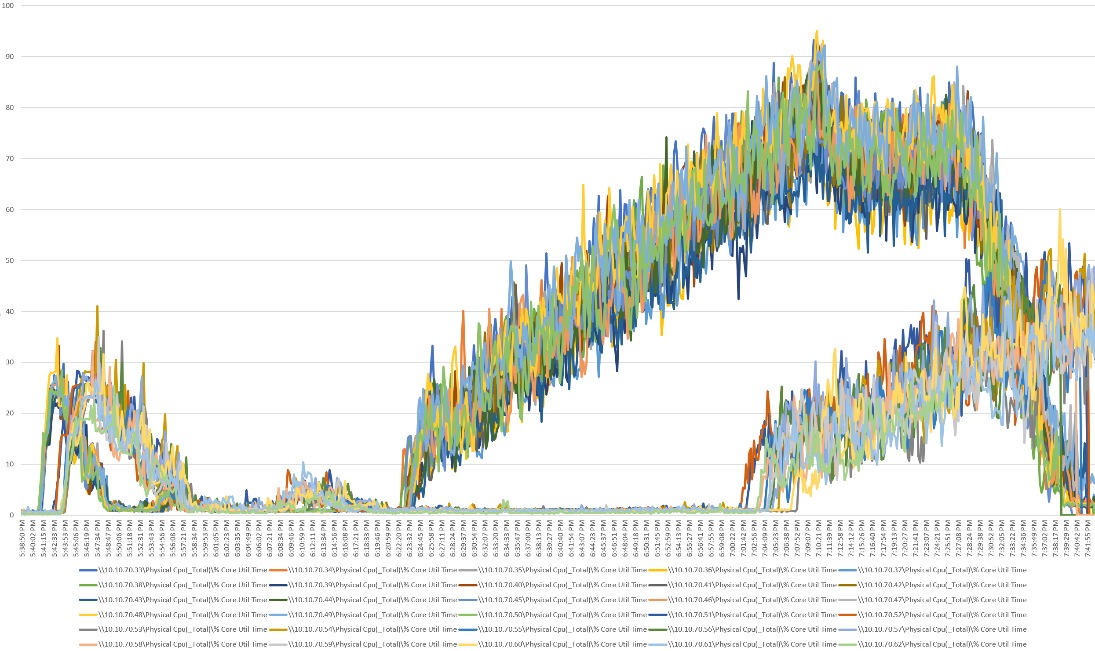
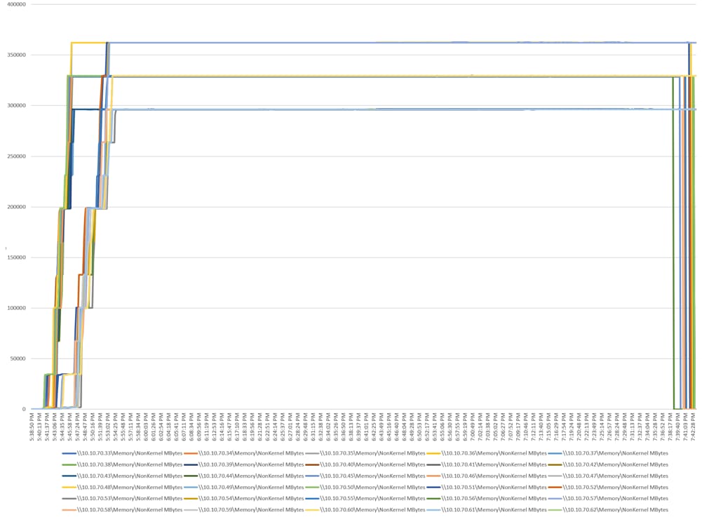
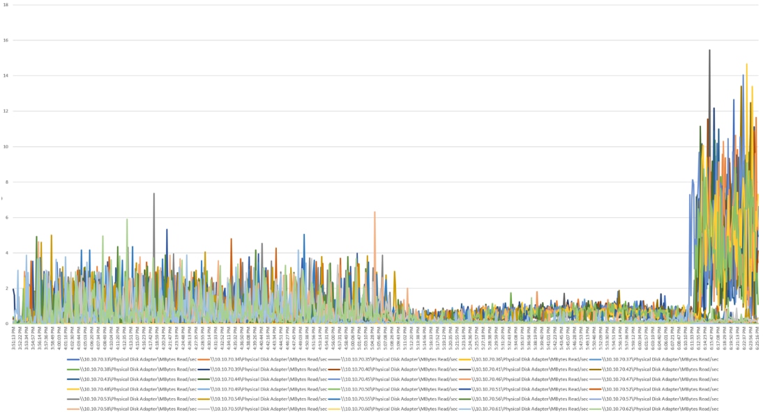
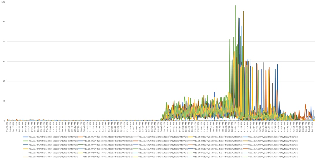
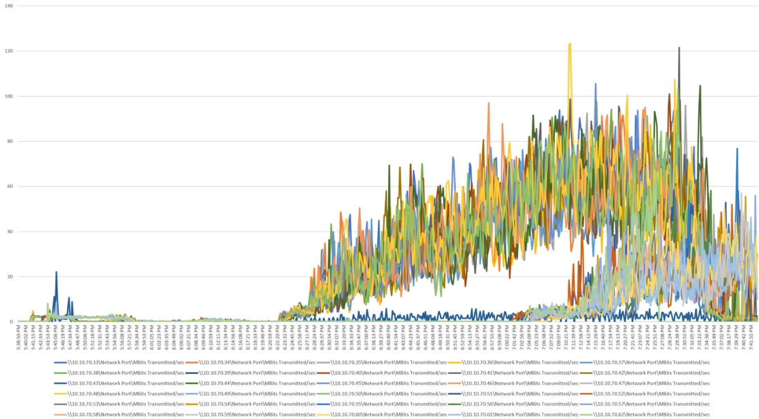
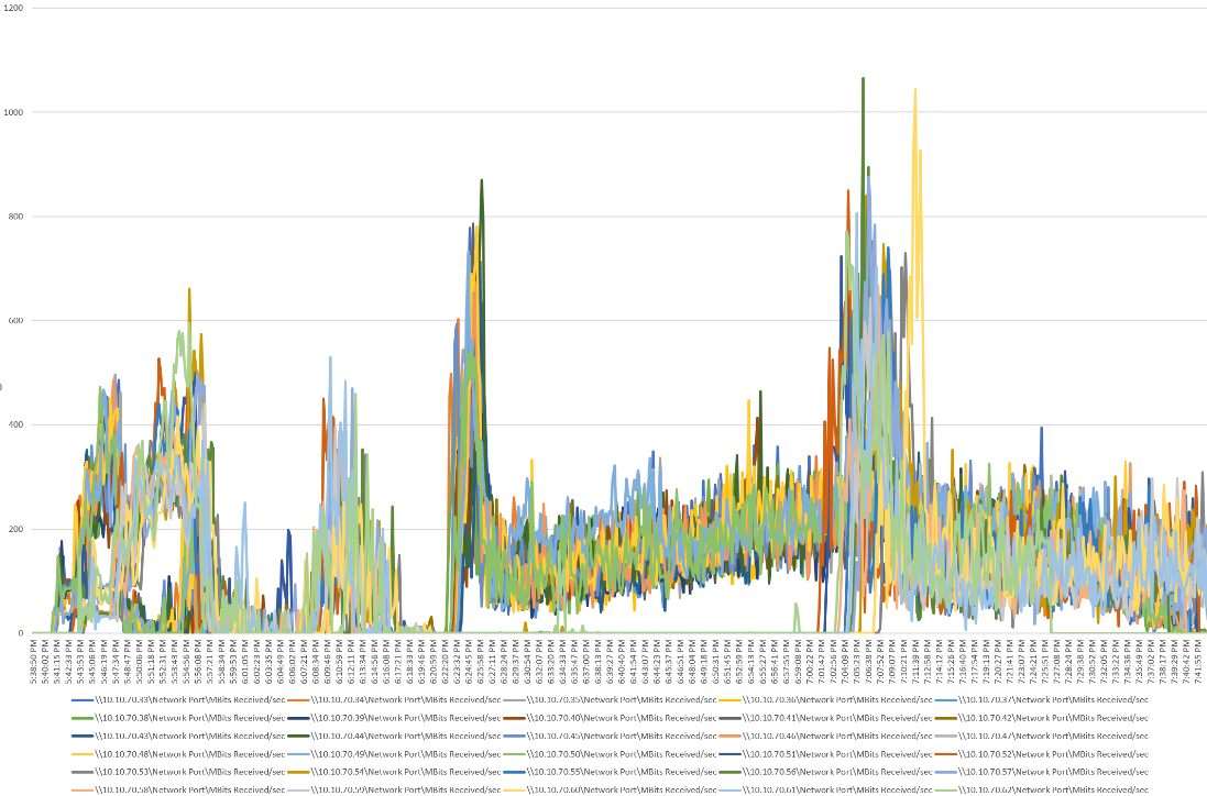
HSD Performance Monitor Data: 6500 Users Scale Testing
Cisco Validated Designs (CVDs) include systems and solutions that are designed, tested, and documented to facilitate and improve customer deployments. These designs incorporate a wide range of technologies and products into a portfolio of solutions that have been developed to address the business needs of customers. Cisco, Pure and Citrix have partner to deliver this document, which serves as a specific step-by-step guide for implementing this solution. This Cisco Validated Design provides an efficient architectural design that is based on customer requirements. The solution that follows is a validated approach for deploying Cisco, Pure, VMware and Citrix technologies as a shared, high performance, resilient, virtual desktop infrastructure.
This document provides a reference architecture and design guide for up to a 6500-seat Hosted Shared Desktop, 5500-Seat Non-persistent VDI and 5000-seat Persistent VDI with Knowledge workers workload. The end user computing environment is on FlashStack Data Center with 4th Generation Cisco UCS and Pure Storage® FlashArray//X70 R2 with 100 percent DirectFlash Modules and DirectFlash Software. The solution includes Citrix Virtual Apps and Desktops 7.15 LTSR server-based Hosted Shared Desktop Windows Sever 2019 sessions, Citrix Virtual Apps and Desktops persistent Microsoft Windows 10 virtual desktops and Citrix Virtual Apps and Desktops non-persistent Microsoft Windows 10 virtual desktops on VMware vSphere 6.7U3 hypervisor.
The solution is a predesigned, best-practice data center architecture built on the FlashStack reference architecture. The FlashStack Data Center used in this validation includes Cisco Unified Computing System (Cisco UCS), the Cisco Nexus® 9000 family of switches, Cisco MDS 9000 family of Fibre Channel (FC) switches and Pure All-NVMe FlashArray//X system.
This solution is 100 percent virtualized on fifth generation Cisco UCS B200 M5 blade servers, booting VMware vSphere 6.7 Update 3 through FC SAN from the FlashArray//X70 R2 storage array. Where applicable the document provides best practice recommendations and sizing guidelines for customer deployment of this solution.
This solution provides an outstanding virtual desktop end-user experience as measured by the Login VSI 4.1.39.6 Knowledge Worker workload running in benchmark mode, providing a large-scale building block that can be replicated to confidently scale-out to tens of thousands of users.
Introduction
The current industry trend in data center design is towards shared infrastructures. By using virtualization along with pre-validated IT platforms, enterprise customers have embarked on the journey to the cloud by moving away from application silos and toward shared infrastructure that can be quickly deployed, thereby increasing agility, and reducing costs. Cisco, Pure Storage, Citrix and VMware have partnered to deliver this Cisco Validated Design, which uses best of breed storage, server and network components to serve as the foundation for desktop virtualization workloads, enabling efficient architectural designs that can be quickly and confidently deployed.
Audience
The audience for this document includes, but is not limited to; sales engineers, field consultants, professional services, IT managers, partner engineers, and customers who want to take advantage of an infrastructure built to deliver IT efficiency and enable IT innovation.
Purpose of this Document
This document provides a step-by-step design, configuration and implementation guide for the Cisco Validated Design for a large-scale Citrix Virtual Apps and Desktops 7.15 mixed workload solution with Pure Storage FlashArray//X array, Cisco UCS Blade Servers, Cisco Nexus 9000 series Ethernet switches and Cisco MDS 9100 series Multilayer Fibre channel switches.
What’s New in this Release?
This is the Citrix Virtual Apps and Desktops 7.15 Virtual Desktop Infrastructure (VDI) deployment Cisco Validated Design with Cisco UCS 5th generation servers and Pure X-Series system.
It incorporates the following features:
· Cisco UCS B200 M5 blade servers with Intel Xeon® Gold 6230 CPU
· 64GB DDR4-2933-MHz memory
· Support for the Cisco UCS 4.0(4g) release
· Support for the latest release of Pure Storage FlashArray//X70 R2 hardware and Purity//FA v5.3.6
· VMware vSphere 6.7 U3 Hypervisor
· Citrix Virtual Apps and Desktops 7.15 LTSR CU4 Server 2019 RDS hosted shared virtual desktops
· Citrix Virtual Apps and Desktops 7.15 LTSR CU4 non-persistent hosted virtual Windows 10 desktops provisioned with Citrix Provisioning Services
· Citrix Virtual Apps and Desktops 7.15 LTSR CU4 persistent full clones hosted virtual Windows 10 desktops provisioned with Citrix Machine Creation Services
The data center market segment is shifting toward heavily virtualized private, hybrid and public cloud computing models running on industry-standard systems. These environments require uniform design points that can be repeated for ease of management and scalability.
These factors have led to the need for predesigned computing, networking and storage building blocks optimized to lower the initial design cost, simplify management, and enable horizontal scalability and high levels of utilization.
The use cases include:
· Enterprise Data Center
· Service Provider Data Center
· Large Commercial Data Center
FlashStack provides a jointly supported solution by Cisco and Pure Storage. Bringing a carefully validated architecture built on superior compute, world class networking, and the leading innovations in all flash storage.
The portfolio of validated offerings from FlashStack includes but is not limited to the following:
· Consistent performance: FlashStack provides higher, more consistent performance than disk-based solutions and delivers a converged infrastructure based on all-flash that provides non-disruptive upgrades and scalability.
· Cost savings: FlashStack uses less power, cooling, and data center space when compared to legacy disk/hybrid storage. It provides industry-leading storage data reduction and exceptional storage density.
· Simplicity: FlashStack requires low ongoing maintenance and reduces operational overhead. It also scales simply and smoothly in step with business requirements.
· Deployment choices: It is available as a custom-built single unit from FlashStack partners, but organizations can also deploy using equipment from multiple sources, including equipment they already own.
· Unique business model: The Pure Storage Evergreen Storage Model enables companies to keep their storage investments forever, which means no more forklift upgrades and no more downtime.
· Mission-critical resiliency: FlashStack offers best in class performance by providing active-active resiliency, no single point of failure, and non-disruptive operations, enabling organizations to maximize productivity.
· Support choices: Focused, high-quality single-number reach for FlashStack support is available from FlashStack Authorized Support Partners. Single-number support is also available directly from Cisco Systems as part of the Cisco Solution Support for Data Center offering. Support for FlashStack components is also available from Cisco, VMware, and Pure Storage individually and leverages TSANet for resolution of support queries between vendors.
This Cisco Validated Design prescribes a defined set of hardware and software that serves as an integrated foundation for both Citrix Virtual Apps and Desktops Microsoft Windows 10 virtual desktops and Citrix Virtual Apps and Desktops server desktop sessions based on Microsoft Server 2019.
The mixed workload solution includes Pure Storage FlashArray//X®, Cisco Nexus® and MDS networking, the Cisco Unified Computing System (Cisco UCS®), Citrix Virtual Apps and Desktops and VMware vSphere® software in a single package. The design is space optimized such that the network, compute, and storage required can be housed in one data center rack. Switch port density enables the networking components to accommodate multiple compute and storage configurations of this kind.
The infrastructure is deployed to provide Fibre Channel-booted hosts with block-level access to shared storage. The reference architecture reinforces the "wire-once" strategy, because as additional storage is added to the architecture, no re-cabling is required from the hosts to the Cisco UCS fabric interconnect.
The combination of technologies from Cisco Systems, Inc., Pure Storage Inc., and Citrix Systems Inc. produced a highly efficient, robust, and affordable desktop virtualization solution for a hosted virtual desktop and hosted shared desktop mixed deployment supporting different use cases. Key components of this solution include the following:
· More power, same size. Cisco UCS B200 M5 half-width blade with dual 20-core 2.1 GHz Intel ® Xeon ® Scalable Family Gold (6230) processors and 768 GB of memory for Citrix Virtual Apps and Desktops hosts supports more virtual desktop workloads than the previously released generation processors on the same hardware. The Intel 20-core 2.1 GHz Intel ® Xeon ® Gold Scalable Family (6230) processors used in this study provided a balance between increased per-blade capacity and cost.
· Fault-tolerance with high availability built into the design. The various designs are based on using one Unified Computing System chassis with multiple Cisco UCS B200 M5 blades for virtualized desktop and infrastructure workloads. The design provides N+1 server fault tolerance for hosted virtual desktops, hosted shared desktops and infrastructure services.
· Stress-tested to the limits during aggressive boot scenario. The servers hosting Hosted Shared Desktop sessions and VDI shared and statically assigned desktop environment booted and registered with the Citrix Delivery Controllers within very short time, providing our customers with an extremely fast, reliable cold-start desktop virtualization system.
· Stress-tested to the limits during simulated login storms. All simulated users logged in and started running workloads up to steady state in 48-minutes without overwhelming the processors, exhausting memory or exhausting the storage subsystems, providing customers with a desktop virtualization system that can easily handle the most demanding login and startup storms.
· Ultra-condensed computing for the data center. The rack space required to support the system is less than a single 42U rack, conserving valuable data center floor space.
· All Virtualized: This Cisco Validated Design (CVD) presents a validated design that is 100 percent virtualized on VMware ESXi 6.7 U3. All of the virtual desktops, user data, profiles, and supporting infrastructure components, including Active Directory, SQL Servers, Citrix Virtual Apps and Desktops components, XenDesktop VDI desktops and XenApp servers were hosted as virtual machines. This provides customers with complete flexibility for maintenance and capacity additions because the entire system runs on the FlashStack converged infrastructure with stateless Cisco UCS Blade servers and Pure FC storage.
· Cisco maintains industry leadership with the new Cisco UCS Manager 4.0(4g) software that simplifies scaling, guarantees consistency, and eases maintenance. Cisco’s ongoing development efforts with Cisco UCS Manager (UCSM), Cisco UCS Central, Cisco UCS Director and Cisco Intersight insure that customer environments are consistent locally, across Cisco UCS Domains and across the globe, our software suite offers increasingly simplified operational and deployment management and it continues to widen the span of control for customer organizations’ subject matter experts in compute, storage and network.
· Our 25G unified fabric story gets additional validation on Cisco UCS 6400 Series Fabric Interconnects as Cisco runs more challenging workload testing, while maintaining unsurpassed user response times.
· Cisco SAN architectural benefit of the next-generation 32-Gb fabric switches address the requirement for highly scalable, virtualized, intelligent SAN infrastructure in current-generation data center environments.
· Pure All-NVMe FlashArray//X70 R2 storage array provides industry-leading storage solutions that efficiently handle the most demanding I/O bursts (for example, login storms), profile management, and user data management, deliver simple and flexible business continuance, and help reduce storage cost per desktop.
· Pure All-NVMe FlashArray//X70 R2 storage array provides a simple to understand storage architecture for hosting all user data components (virtual machines, profiles, user data) on the same storage array.
· Pure Storage software enables to seamlessly add, upgrade or remove capacity and/or controllers from the infrastructure to meet the needs of the virtual desktops transparently.
· Pure Storage Management UI for VMware vSphere hypervisor has deep integrations with vSphere, providing easy-button automation for key storage tasks such as storage repository provisioning, storage resize, directly from vCenter.
· Citrix Virtual Apps and Desktops Advantage. Citrix Virtual Apps and Desktops are virtualization solutions that give IT control of virtual machines, applications, licensing, and security while providing anywhere access for any device.
Citrix Virtual Apps and Desktops provides the following:
· End users to run applications and desktops independently of the device's operating system and interface.
· Administrators to manage the network and control access from selected devices or from all devices.
· Administrators to manage an entire network from a single data center.
· Citrix Virtual Apps and Desktops share a unified architecture called FlexCast Management Architecture (FMA). FMA's key features are the ability to run multiple versions from a single Site and integrated provisioning.
· Optimized to achieve the best possible performance and scale. For hosted shared desktop sessions, the best performance was achieved when the number of vCPUs assigned to the VMware 7 RDS virtual machines did not exceed the number of hyper-threaded (logical) cores available on the server. In other words, maximum performance is obtained when not overcommitting the CPU resources for the virtual machines running virtualized RDS systems.
· Provisioning desktop machines made easy. Citrix provides two core provisioning methods for Citrix Virtual Apps and Desktops virtual machines: Citrix Provisioning Services for pooled virtual desktops and Citrix Virtual Apps and Desktops virtual servers and Citrix Machine Creation Services for pooled or persistent virtual desktops. This paper provides guidance on how to use each method and documents the performance of each technology.
Cisco Desktop Virtualization Solutions: Data Center
The Evolving Workplace
Today’s IT departments are facing a rapidly evolving workplace environment. The workforce is becoming increasingly diverse and geographically dispersed, including offshore contractors, distributed call center operations, knowledge and task workers, partners, consultants, and executives connecting from locations around the world at all times.
This workforce is also increasingly mobile, conducting business in traditional offices, conference rooms across the enterprise campus, home offices, on the road, in hotels, and at the local coffee shop. This workforce wants to use a growing array of client computing and mobile devices that they can choose based on personal preference.
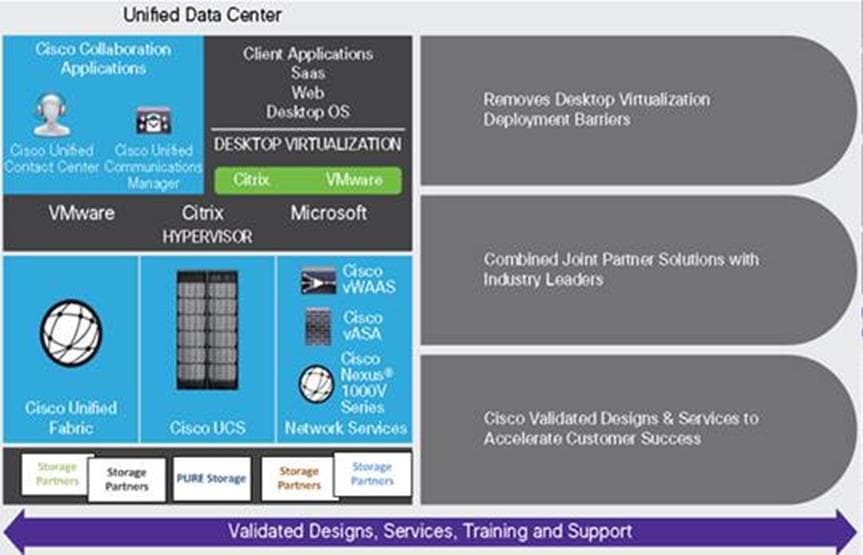
These trends are increasing pressure on IT to ensure protection of corporate data and prevent data leakage or loss through any combination of user, endpoint device, and desktop access scenarios (Figure 1).
These challenges are compounded by desktop refresh cycles to accommodate aging PCs and bounded local storage and migration to new operating systems, specifically Microsoft Windows 10 and productivity tools, specifically Microsoft Office 2016.
Some of the key drivers for desktop virtualization are increased data security and reduced TCO through increased control and reduced management costs.
Cisco Desktop Virtualization Focus
Cisco focuses on three key elements to deliver the best desktop virtualization data center infrastructure: simplification, security, and scalability. The software combined with platform modularity provides a simplified, secure, and scalable desktop virtualization platform.
Simplified
Cisco UCS provides a radical new approach to industry-standard computing and provides the core of the data center infrastructure for desktop virtualization. Among the many features and benefits of Cisco UCS are the drastic reduction in the number of servers needed and in the number of cables used per server, and the capability to rapidly deploy or re-provision servers through Cisco UCS service profiles. With fewer servers and cables to manage and with streamlined server and virtual desktop provisioning, operations are significantly simplified. Thousands of desktops can be provisioned in minutes with Cisco UCS Manager Service Profiles and Cisco storage partners’ storage-based cloning. This approach accelerates the time to productivity for end users, improves business agility, and allows IT resources to be allocated to other tasks.
Cisco UCS Manager automates many mundane, error-prone data center operations such as configuration and provisioning of server, network, and storage access infrastructure. In addition, Cisco UCS B-Series Blade Servers and Cisco UCS C-Series Rack Servers with large memory footprints enable high desktop density that helps reduce server infrastructure requirements.
Cisco Intersight is Cisco’s systems management platform that delivers intuitive computing through cloud-powered intelligence. This platform offers a more intelligent level of management that enables IT organizations to analyze, simplify, and automate their environments in ways that were not possible with prior generations of tools. This capability empowers organizations to achieve significant savings in Total Cost of Ownership (TCO) and to deliver applications faster in support of new business initiatives. The advantages of the model-based management of the Cisco UCS® platform plus Cisco Intersight are extended to Cisco UCS servers and Cisco HyperFlex™, including Cisco HyperFlex Edge systems.
Simplification also leads to more successful desktop virtualization implementation. Cisco and its technology partners like VMware Technologies, Citrix Systems and Pure Storage have developed integrated, validated architectures, including predefined converged architecture infrastructure packages such as FlashStack. Cisco Desktop Virtualization Solutions have been tested with VMware vSphere, Citrix Virtual Apps and Desktops.
Secure
Although virtual desktops are inherently more secure than their physical predecessors, they introduce new security challenges. Mission-critical web and application servers using a common infrastructure such as virtual desktops are now at a higher risk for security threats. Inter–virtual machine traffic now poses an important security consideration that IT managers need to address, especially in dynamic environments in which virtual machines, using VMware vMotion, move across the server infrastructure.
Desktop virtualization, therefore, significantly increases the need for virtual machine–level awareness of policy and security, especially given the dynamic and fluid nature of virtual machine mobility across an extended computing infrastructure. The ease with which new virtual desktops can proliferate magnifies the importance of a virtualization-aware network and security infrastructure. Cisco data center infrastructure (Cisco UCS and Cisco Nexus Family solutions) for desktop virtualization provides strong data center, network, and desktop security, with comprehensive security from the desktop to the hypervisor. Security is enhanced with segmentation of virtual desktops, virtual machine–aware policies and administration, and network security across the LAN and WAN infrastructure.
Scalable
Growth of a desktop virtualization solution is all but inevitable, so a solution must be able to scale, and scale predictably, with that growth. The Cisco Desktop Virtualization Solutions built on FlashStack Data Center infrastructure supports high virtual-desktop density (desktops per server), and additional servers and storage scale with near-linear performance. FlashStack Data Center provides a flexible platform for growth and improves business agility. Cisco UCS Manager Service Profiles allow on-demand desktop provisioning and make it just as easy to deploy dozens of desktops as it is to deploy thousands of desktops.
Cisco UCS servers provide near-linear performance and scale. Cisco UCS implements the patented Cisco Extended Memory Technology to offer large memory footprints with fewer sockets (with scalability to up to 3 terabyte (TB) of memory with 2- and 4-socket servers). Using unified fabric technology as a building block, Cisco UCS server aggregate bandwidth can scale to up to 40 Gb per server, and the northbound Cisco UCS fabric interconnect can output 3.82 terabits per second (Tbps) at line rate, helping prevent desktop virtualization I/O and memory bottlenecks. Cisco UCS, with its high-performance, low-latency unified fabric-based networking architecture, supports high volumes of virtual desktop traffic, including high-resolution video and communications traffic. In addition, Cisco storage partner Pure, helps maintain data availability and optimal performance during boot and login storms as part of the Cisco Desktop Virtualization Solutions. Recent Cisco Validated Designs for end user computing based on FlashStack solutions have demonstrated scalability and performance.
FlashStack data center provides an excellent platform for growth, with transparent scaling of server, network, and storage resources to support desktop virtualization, data center applications, and cloud computing.
Savings and Success
The simplified, secure, scalable Cisco data center infrastructure for desktop virtualization solutions saves time and money compared to alternative approaches. Cisco UCS enables faster payback and ongoing savings (better ROI and lower TCO) and provides the industry’s greatest virtual desktop density per server, reducing both capital expenditures (CapEx) and operating expenses (OpEx). The Cisco UCS architecture and Cisco Unified Fabric also enables much lower network infrastructure costs, with fewer cables per server and fewer ports required. In addition, storage tiering and deduplication technologies decrease storage costs, reducing desktop storage needs by up to 50 percent.
The simplified deployment of Cisco UCS for desktop virtualization accelerates the time to productivity and enhances business agility. IT staff and end users are more productive more quickly, and the business can respond to new opportunities quickly by deploying virtual desktops whenever and wherever they are needed. The high-performance Cisco systems and network deliver a near-native end-user experience, allowing users to be productive anytime and anywhere.
The ultimate measure of desktop virtualization for any organization is its efficiency and effectiveness in both the near term and the long term. The Cisco Desktop Virtualization Solutions are very efficient, allowing rapid deployment, requiring fewer devices and cables, and reducing costs. The solutions are also very effective, providing the services that end users need on their devices of choice while improving IT operations, control, and data security. Success is bolstered through Cisco’s best-in-class partnerships with leaders in virtualization and storage, and through tested and validated designs and services to help customers throughout the solution lifecycle. Long-term success is enabled through the use of Cisco’s scalable, flexible, and secure architecture as the platform for desktop virtualization.
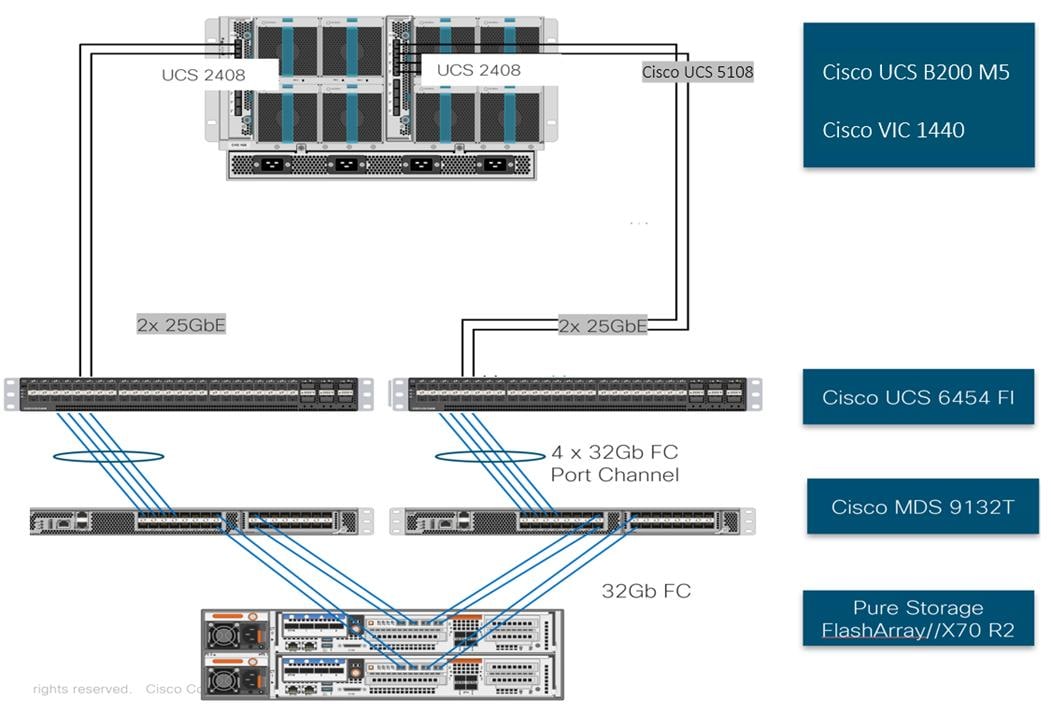
Physical Topology
Compute Connectivity
Each rack server in the design is redundantly connected to the managing fabric interconnects with at least one port to each FI. Ethernet traffic from the upstream network and Fibre Channel frames coming from the FlashArray are converged within the fabric interconnect to be both Ethernet and Fibre Channel over Ethernet and transmitted to the UCS server.
These connections from the 4th Gen Cisco UCS 6454 Fabric Interconnect to the 2408 IOM hosted within the chassis are shown in Figure 2.
The 2408 IOM are shown with 2x25Gbe ports to delivers to the chassis, full population of the 2408 IOM can support 8x25Gbe ports, allowing for an aggregate of 200Gbe to the chassis.
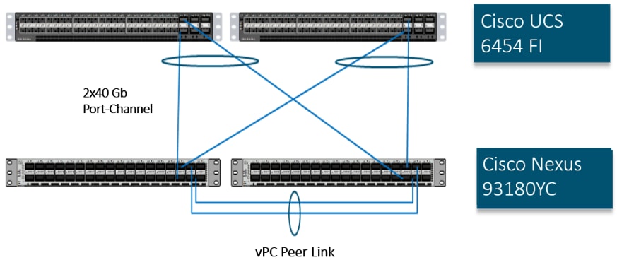
Network Connectivity
The Layer 2 network connection to each Fabric Interconnect is implemented as Virtual Port Channels (vPC) from the upstream Nexus Switches. In the switching environment, the vPC provides the following benefits:
· Allows a single device to use a Port Channel across two upstream devices
· Eliminates Spanning Tree Protocol blocked ports and use all available uplink bandwidth
· Provides a loop-free topology
· Provides fast convergence if either one of the physical links or a device fails
· Helps ensure high availability of the network
The upstream network switches can connect to the Cisco UCS 6454 Fabric Interconnects using 10G, 25G, 40G, or 100G port speeds. In this design, the 100G ports from the 40/100G ports on the 6454 (1/49-54) were used for the virtual port channels.
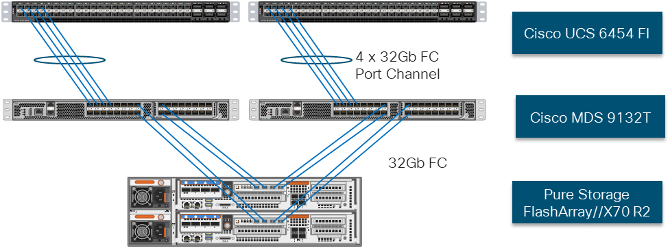
Fibre Channel Storage Connectivity
The Pure Storage FlashArray//X70 R2 platform is connected through both MDS 9132Ts to their respective Fabric Interconnects in a traditional air-gapped A/B fabric design. The Fabric Interconnects are configured in N-Port Virtualization (NPV) mode, known as FC end host mode in UCSM. The MDS has N-Port ID Virtualization (NPIV) enabled. This allows F-port channels to be used between the Fabric Interconnect and the MDS, providing the following benefits:
· Increased aggregate bandwidth between the fabric interconnect and the MDS
· Load balancing across the FC uplinks
· High availability in the event of a failure of one or more uplinks
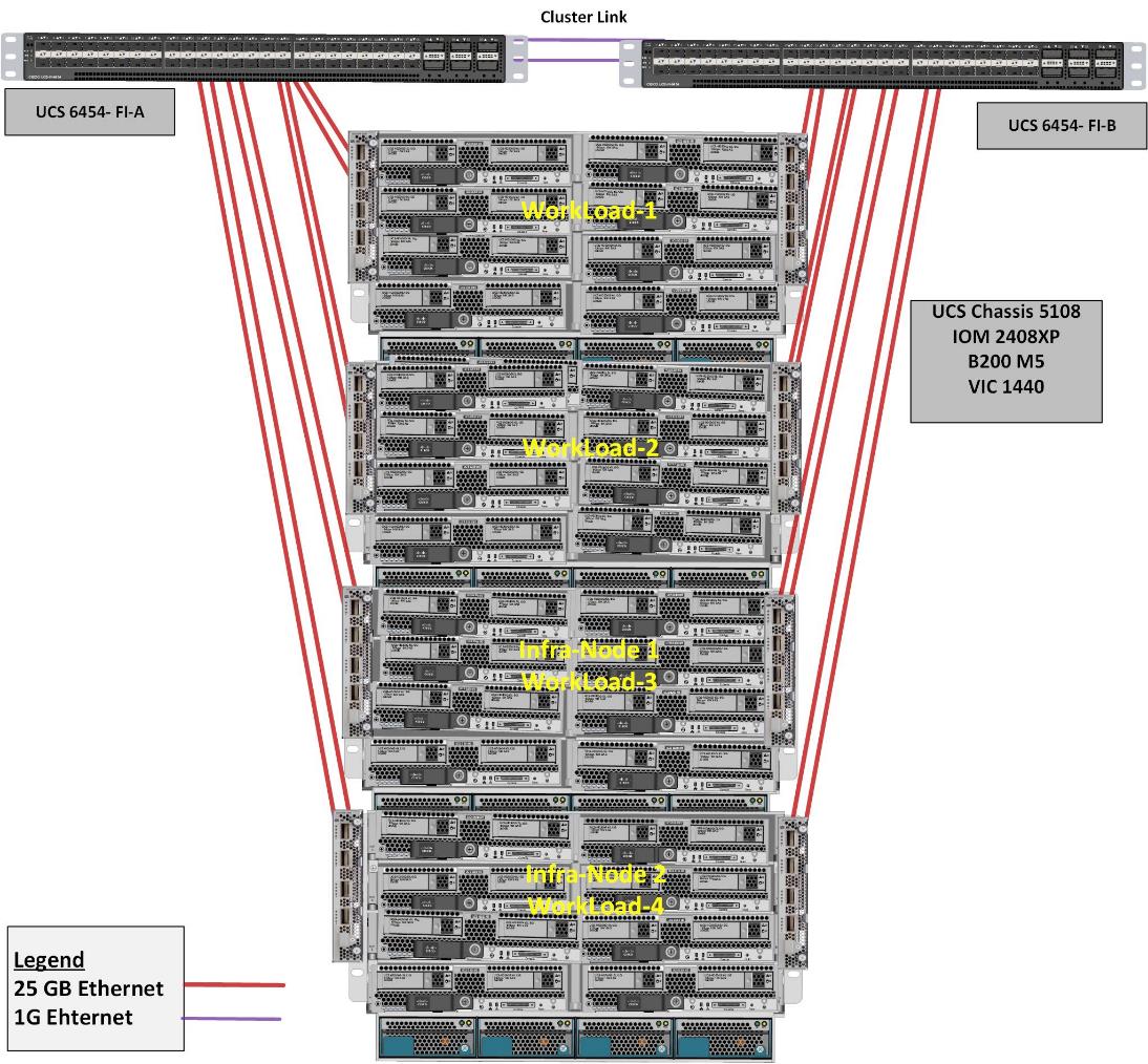
End-to-End Physical Connectivity
FC End-to-End Data Path
The FC end to end path in the design is a traditional air-gapped fabric with identical data path through each fabric as detailed below:
· Each Cisco UCS Server is equipped with a VIC 1400 Series adapter
· In the Cisco B200 M5 server, a VIC 1440 provides 2x25Gbe to IOM A and 2x25Gbe to IOM B through the Cisco UCS Chassis 5108 chassis backplane
· Each IOM is connected to its respective Cisco UCS 6454 Fabric Interconnect using a port-channel for 4-8 links
· Each Cisco UCS 6454 FI connects to the MDS 9132T for the respective SAN fabric using an F-Port channel
· The Pure Storage FlashArray//X70 R2 is connected to both MDS 9132T switches to provide redundant paths through both fabrics
The components of this integrated architecture shown in Figure 5 are:
· Cisco Nexus 93180YC-FX – 10/25/40/100Gbe capable, LAN connectivity to the UCS compute resources
· Cisco UCS 6454 Fabric Interconnect – Unified management of UCS compute, and the compute’s access to storage and networks
· Cisco UCS B200 M5 – High powered blade server, optimized for virtual computing
· Cisco MDS 9132T – 32Gb Fibre Channel connectivity within the architecture, as well as interfacing to resources present in an existing data center
· Pure Storage FlashArray//X70 R2
High Scale HSD and VDI Workload Solution Reference Architecture
Figure 6 illustrates the FlashStack System architecture used in this CVD to support very high scale mixed desktop user workload. It follows Cisco configuration requirements to deliver highly available and scalable architecture.
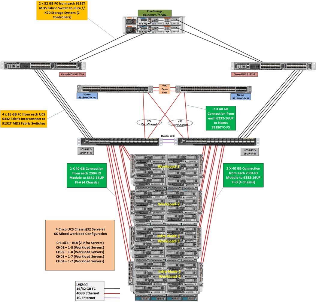
The reference hardware configuration includes:
· Two Cisco Nexus 93180YC-FX switches
· Two Cisco MDS 9132T 32-Gb Fibre Channel switches
· Two Cisco UCS 6454 Fabric Interconnects
· Four Cisco UCS 5108 Blade Chassis
· Two Cisco UCS B200 M5 Blade Servers (2 Server hosting Infrastructure virtual machines)
· Thirty Cisco UCS B200 M5 Blade Servers (for workload)
· One Pure Storage FlashArray//X70 R2 with All-NVMe DirectFlash Modules
For desktop virtualization, the deployment includes Citrix Virtual Apps and Desktops 7.15 LTSR CU4 running on VMware vSphere 6.7 Update 4.
The design is intended to provide a large-scale building block for Citrix Virtual Apps and Desktops workloads consisting of HSD Windows Server 2019 hosted shared desktop sessions and Windows 10 non-persistent and persistent hosted desktops. This is the first CVD where each environment was tested separately using entire infrastructure.
· 6500 Random Hosted Shared Windows 2019 user sessions with office 2016 (PVS) on 30 UCS Hosts
· 5500 Random Pooled Windows 10 Hosted Virtual Desktops with office 2016 (PVS) on 30 UCS Hosts
· 5000 Static Full Copy Windows 10 Hosted Virtual Desktops with office 2016 (MCS) on 30 UCS Hosts
This document guides you through the detailed steps for deploying the base architecture. This procedure explains everything from physical cabling to network, compute, and storage device configurations.
What is FlashStack?
The FlashStack platform, developed by Cisco and Pure Storage, is a flexible, integrated infrastructure solution that delivers pre-validated storage, networking, and server technologies. Cisco and Pure Storage have carefully validated and verified the FlashStack solution architecture and its many use cases while creating a portfolio of detailed documentation, information, and references to assist customers in transforming their data centers to this shared infrastructure model.
FlashStack is a best practice data center architecture that includes the following components:
· Cisco Unified Computing System
· Cisco Nexus Switches
· Cisco MDS Switches
· Pure Storage FlashArray
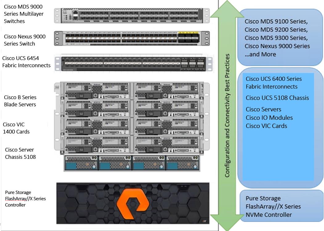
As shown in Figure 7, these components are connected and configured according to best practices of both Cisco and Pure Storage and provide the ideal platform for running a variety of enterprise database workloads with confidence. FlashStack can scale up for greater performance and capacity (adding compute, network, or storage resources individually as needed), or it can scale out for environments that require multiple consistent deployments.
The reference architecture covered in this document leverages the Pure Storage FlashArray//X70 R2 Controller with NVMe based DirectFlash modules for Storage, Cisco UCS B200 M5 Blade Server for Compute, Cisco Nexus 9000, and Cisco MDS 9100 Series for the switching element and Cisco Fabric Interconnects 6300 Series for System Management. As shown in Figure 7, FlashStack Architecture can maintain consistency at scale. Each of the component families shown in (Cisco UCS, Cisco Nexus, Cisco MDS, Cisco FI and Pure Storage) offers platform and resource options to scale the infrastructure up or down, while supporting the same features and functionality that are required under the configuration and connectivity best practices of FlashStack.
FlashStack Solution Benefits
FlashStack provides a jointly supported solution by Cisco and Pure Storage. Bringing a carefully validated architecture built on superior compute, world-class networking, and the leading innovations in all flash storage. The portfolio of validated offerings from FlashStack includes but is not limited to the following:
· Consistent Performance and Scalability
- Consistent sub-millisecond latency with 100 percent NVMe enterprise flash storage
- Consolidate hundreds of enterprise-class applications in a single rack
- Scalability through a design for hundreds of discrete servers and thousands of virtual machines, and the capability to scale I/O bandwidth to match demand without disruption
- Repeatable growth through multiple FlashStack CI deployments
· Operational Simplicity
- Fully tested, validated, and documented for rapid deployment
- Reduced management complexity
- No storage tuning or tiers necessary
- 3x better data reduction without any performance impact
· Lowest TCO
- Dramatic savings in power, cooling and space with Cisco UCS and 100 percent Flash
- Industry leading data reduction
- Free FlashArray controller upgrades every three years with Forever Flash™
· Mission Critical and Enterprise Grade Resiliency
- Highly available architecture with no single point of failure
- Non-disruptive operations with no downtime
- Upgrade and expand without downtime or performance loss
- Native data protection: snapshots and replication
Cisco and Pure Storage have also built a robust and experienced support team focused on FlashStack solutions, from customer account and technical sales representatives to professional services and technical support engineers. The support alliance between Pure Storage and Cisco gives customers and channel services partners direct access to technical experts who collaborate with cross vendors and have access to shared lab resources to resolve potential issues.
What’s New in this FlashStack Release
This CVD of the FlashStack release introduces new hardware with the Pure Storage FlashArray//X, that is 100 percent NVMe enterprise class all-flash array along with Cisco UCS B200 M5 Blade Servers featuring the Intel Xeon Scalable Family of CPUs. This is the second Oracle RAC Database deployment Cisco Validated Design with Pure Storage. It incorporates the following features:
· Pure Storage FlashArray//X70 R2 purity//FA 5.3.6
· Cisco 4th Gen UCS 6454 with IOM 2408
· Cisco UCS Manager 4.0(4g)
· VMware vSphere 6.7 U3 Hypervisor
· Citrix Virtual Apps and Desktops 7.15 LTSR Cumulative Update 4 (CU4)
· Citrix Provisioning Server 7.15.15 CU4
Configuration Guidelines
This Cisco Validated Design provides instruction to deploy a fully redundant, highly available 6500/5500/5000 seat HSD/VDI-Non-Persistent/VDI-Persistent virtual desktop solution with VMware on a FlashStack Data Center architecture. The configuration guidelines detail which redundant component is being configured with each step.
The redundancy contained within the entire infrastructure is as follows:
· Storage Redundancy: FlashArray//X70 R2 Controller 0 and Controller 1
· Switching Redundancy: Cisco Nexus A and Cisco Nexus B
· SAN Switch redundancy: Cisco MDS A and Cisco MDS B
· Compute Redundancy: Cisco UCS 6454 FI- A and FI -B
· Compute server redundancy: N+1
· Infrastructure Server redundancy: Infra Server 1 and Infra Server 2
Additionally, this document details the steps to provision multiple Cisco UCS hosts, and these are identified sequentially: VM-Host-Infra-01, VM-Host-Infra-02, VM-Host-RDSH-01, VM-Host-VDI-01 and so on. Finally, to indicate that you should include information pertinent to your environment in a given step, <text> appears as part of the command structure.
This section describes the components used in this solution.
Cisco Unified Computing System
Cisco UCS Manager (UCSM) provides unified, embedded management of all software and hardware components of the Cisco Unified Computing System™ (Cisco UCS) through an intuitive GUI, a CLI, and an XML API. UCSM provides a unified management domain with centralized management capabilities and can control multiple chassis and thousands of virtual machines.
Cisco UCS is a next-generation data center platform that unites computing, networking, and storage access. The platform, optimized for virtual environments, is designed using open industry-standard technologies and aims to reduce total cost of ownership (TCO) and increase business agility. The system integrates a low-latency; lossless 40 Gigabit Ethernet unified network fabric with enterprise-class, x86-architecture servers. It is an integrated, scalable, multi-chassis platform in which all resources participate in a unified management domain.
Cisco Unified Computing System Components
The main components of Cisco UCS are:
· Compute: The system is based on an entirely new class of computing system that incorporates blade servers based on Intel® Xeon® Scalable Family processors.
· Network: The system is integrated on a low-latency, lossless, 25-Gbe unified network fabric. This network foundation consolidates LANs, SANs, and high-performance computing (HPC) networks, which are separate networks today. The unified fabric lowers costs by reducing the number of network adapters, switches, and cables needed, and by decreasing the power and cooling requirements.
· Virtualization: The system unleashes the full potential of virtualization by enhancing the scalability, performance, and operational control of virtual environments. Cisco security, policy enforcement, and diagnostic features are now extended into virtualized environments to better support changing business and IT requirements.
· Storage access: The system provides consolidated access to local storage, SAN storage, and network-attached storage (NAS) over the unified fabric. With storage access unified, Cisco UCS can access storage over Ethernet, Fibre Channel, Fibre Channel over Ethernet (FCoE), and Small Computer System Interface over IP (iSCSI) protocols. This capability provides customers with choice for storage access and investment protection. In addition, server administrators can pre-assign storage-access policies for system connectivity to storage resources, simplifying storage connectivity and management and helping increase productivity.
· Management: Cisco UCS uniquely integrates all system components, enabling the entire solution to be managed as a single entity by Cisco UCS Manager. Cisco UCS Manager has an intuitive GUI, a CLI, and a robust API for managing all system configuration processes and operations.
Cisco UCS is designed to deliver:
· Reduced TCO and increased business agility
· Increased IT staff productivity through just-in-time provisioning and mobility support
· A cohesive, integrated system that unifies the technology in the data center; the system is managed, serviced, and tested as a whole
· Scalability through a design for hundreds of discrete servers and thousands of virtual machines and the capability to scale I/O bandwidth to match demand
· Industry standards supported by a partner ecosystem of industry leaders
Cisco UCS Manager provides unified, embedded management of all software and hardware components of the Cisco Unified Computing System across multiple chassis, rack servers, and thousands of virtual machines. Cisco UCS Manager manages Cisco UCS as a single entity through an intuitive GUI, a CLI, or an XML API for comprehensive access to all Cisco UCS Manager Functions.
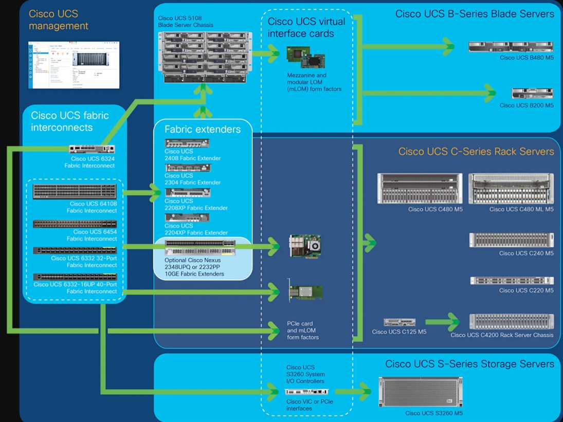
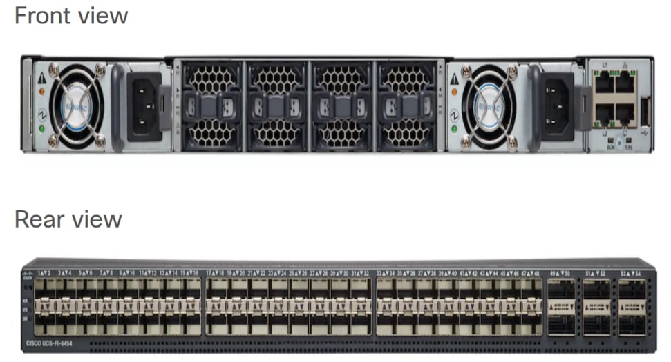
Cisco UCS Fabric Interconnect
The Cisco UCS 6400 Series Fabric Interconnects are a core part of the Cisco Unified Computing System, providing both network connectivity and management capabilities for the system. The Cisco UCS 6400 Series offer line-rate, low-latency, lossless 10/25/40/100 Gigabit Ethernet, Fibre Channel over Ethernet (FCoE), and Fibre Channel functions.
The Cisco UCS 6400 Series provide the management and communication backbone for the Cisco UCS B-Series Blade Servers, Cisco UCS 5108 B-Series Server Chassis, Cisco UCS Managed C-Series Rack Servers, and Cisco UCS S-Series Storage Servers. All servers attached to a Cisco UCS 6400 Series Fabric Interconnect become part of a single, highly available management domain. In addition, by supporting a unified fabric, Cisco UCS 6400 Series Fabric Interconnect provides both the LAN and SAN connectivity for all servers within its domain.
From a networking perspective, the Cisco UCS 6400 Series use a cut-through architecture, supporting deterministic, low-latency, line-rate 10/25/40/100 Gigabit Ethernet ports, switching capacity of 3.82 Tbps for the 6454, 7.42 Tbps for the 64108, and 200 Gbe bandwidth between the Fabric Interconnect 6400 series and the IOM 2408 per 5108 blade chassis, independent of packet size and enabled services. The product family supports Cisco low-latency, lossless 10/25/40/100 Gigabit Ethernet unified network fabric capabilities, which increase the reliability, efficiency, and scalability of Ethernet networks. The fabric interconnect supports multiple traffic classes over a lossless Ethernet fabric from the server through the fabric interconnect. Significant TCO savings come from an FCoE-optimized server design in which Network Interface Cards (NICs), Host Bus Adapters (HBAs), cables, and switches can be consolidated.
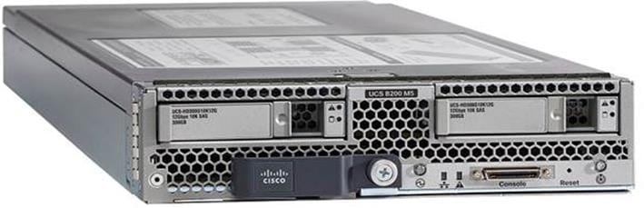
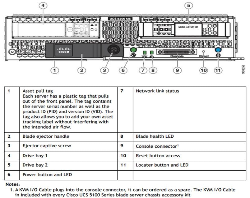
Cisco UCS B200 M5 Blade Server
The Cisco UCS B200 M5 Blade Server (Figure 10 and Figure 11) is a density-optimized, half-width blade server that supports two CPU sockets for Intel Xeon processor 6230 Gold series CPUs and up to 24 DDR4 DIMMs. It supports one modular LAN-on-motherboard (LOM) dedicated slot for a Cisco virtual interface card (VIC) and one mezzanine adapter. In additions, the Cisco UCS B200 M5 supports an optional storage module that accommodates up to two SAS or SATA hard disk drives (HDDs) or solid-state disk (SSD) drives. You can install up to eight Cisco UCS B200 M5 servers in a chassis, mixing them with other models of Cisco UCS blade servers in the chassis if desired.
Cisco UCS combines Cisco UCS B-Series Blade Servers and Cisco UCS C-Series Rack Servers with networking and storage access into a single converged system with simplified management, greater cost efficiency and agility, and increased visibility and control. The Cisco UCS B200 M5 Blade Server is one of the newest servers in the Cisco UCS portfolio.
The Cisco UCS B200 M5 delivers performance, flexibility, and optimization for data centers and remote sites. This enterprise-class server offers market-leading performance, versatility, and density without compromise for workloads ranging from web infrastructure to distributed databases. The Cisco UCS B200 M5 can quickly deploy stateless physical and virtual workloads with the programmable ease of use of the Cisco UCS Manager software and simplified server access with Cisco® Single Connect technology. Based on the Intel Xeon® processor Gold 6230 product family, it offers up to 3 TB of memory using 128GB DIMMs, up to two disk drives, and up to 320 GB of I/O throughput. The Cisco UCS B200 M5 offers exceptional levels of performance, flexibility, and I/O throughput to run your most demanding applications.
In addition, Cisco UCS has the architectural advantage of not having to power and cool excess switches, NICs, and HBAs in each blade server chassis. With a larger power budget per blade server, it provides uncompromised expandability and capabilities, as in the new Cisco UCS B200 M5 server with its leading memory-slot capacity and drive capacity.
The Cisco UCS B200 M5 provides:
· Latest Intel® Xeon® Scalable processors with up to 28 cores per socket
· Up to 24 DDR4 DIMMs for improved performance
· Intel 3D XPoint-ready support, with built-in support for next-generation nonvolatile memory technology
· Two GPUs
· Two Small-Form-Factor (SFF) drives
· Two Secure Digital (SD) cards or M.2 SATA drives
· Up to 80 Gbe of I/O throughput
Main Features
The Cisco UCS B200 M5 server is a half-width blade. Up to eight servers can reside in the 6-Rack-Unit (6RU) Cisco UCS 5108 Blade Server Chassis, offering one of the highest densities of servers per rack unit of blade chassis in the industry. You can configure the Cisco UCS B200 M5 to meet your local storage requirements without having to buy, power, and cool components that you do not need.
The Cisco UCS B200 M5 provides these main features:
· Up to two Intel Xeon Scalable CPUs with up to 28 cores per CPU
· 24 DIMM slots for industry-standard DDR4 memory at speeds up to 2666 MHz, with up to 3 TB of total memory when using 128-GB DIMMs
· Modular LAN On Motherboard (mLOM) card with Cisco UCS Virtual Interface Card (VIC) 1440 or 1340, a 2-port, 40 Gigabit Ethernet, Fibre Channel over Ethernet (FCoE)–capable mLOM mezzanine adapter
· Optional rear mezzanine VIC with two 40-Gbe unified I/O ports or two sets of 4 x 10-Gbe unified I/O ports, delivering 80 Gbe to the server; adapts to either 10- or 40-Gbe fabric connections
· Two optional, hot-pluggable, hard-disk drives (HDDs), solid-state drives (SSDs), or NVMe 2.5-inch drives with a choice of enterprise-class RAID or pass-through controllers
· Cisco FlexStorage local drive storage subsystem, which provides flexible boot and local storage capabilities and allows you to boot from dual, mirrored SD cards
· Support for up to two optional GPUs
· Support for up to one rear storage mezzanine card
· Support for one 16-GB internal flash USB drive
For more information about Cisco UCS B200 M5, see the Cisco UCS B200 M5 Blade Server Specsheet.
Table 1 Ordering Information
| Part Number |
Description |
| UCSB-B200-M5 |
UCS B200 M5 Blade w/o CPU, mem, HDD, mezz |
| UCSB-B200-M5-U |
UCS B200 M5 Blade w/o CPU, mem, HDD, mezz (UPG) |
| UCSB-B200-M5-CH |
UCS B200 M5 Blade w/o CPU, mem, HDD, mezz, Drive bays, HS |
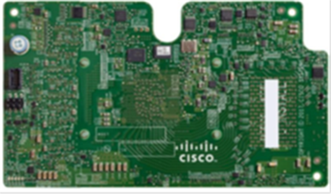
Cisco UCS VIC1340 Converged Network Adapter
The Cisco UCS VIC 1440 (Figure 12) is a single-port 40-Gbe or 4x10-Gbe Ethernet/FCoE capable modular LAN On Motherboard (mLOM) designed exclusively for the M5 generation of Cisco UCS B-Series Blade Servers. When used in combination with an optional port expander, the Cisco UCS VIC 1440 capabilities are enabled for two ports of 40-Gbe Ethernet. The Cisco UCS VIC 1440 enables a policy-based, stateless, agile server infrastructure that can present to the host PCIe standards-compliant interfaces that can be dynamically configured as either NICs or HBAs.
Cisco Switching
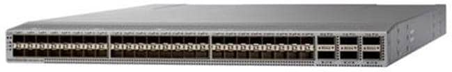
Cisco Nexus 93180YC-FX Switches
The Cisco Nexus 93180YC-EX Switch provides a flexible line-rate Layer 2 and Layer 3 feature set in a compact form factor. Designed with Cisco Cloud Scale technology, it supports highly scalable cloud architectures. With the option to operate in Cisco NX-OS or Application Centric Infrastructure (ACI) mode, it can be deployed across enterprise, service provider, and Web 2.0 data centers.
· Architectural Flexibility
- Includes top-of-rack or middle-of-row fiber-based server access connectivity for traditional and leaf-spine architectures
- Leaf node support for Cisco ACI architecture is provided in the roadmap
- Increase scale and simplify management through Cisco Nexus 2000 Fabric Extender support
· Feature Rich
- Enhanced Cisco NX-OS Software is designed for performance, resiliency, scalability, manageability, and programmability
- ACI-ready infrastructure helps users take advantage of automated policy-based systems management
- Virtual Extensible LAN (VXLAN) routing provides network services
- Rich traffic flow telemetry with line-rate data collection
- Real-time buffer utilization per port and per queue, for monitoring traffic micro-bursts and application traffic patterns
· Highly Available and Efficient Design
- High-density, non-blocking architecture
- Easily deployed into either a hot-aisle and cold-aisle configuration
- Redundant, hot-swappable power supplies and fan trays
· Simplified Operations
- Power-On Auto Provisioning (POAP) support allows for simplified software upgrades and configuration file installation
- An intelligent API offers switch management through remote procedure calls (RPCs, JSON, or XML) over a HTTP/HTTPS infrastructure
- Python Scripting for programmatic access to the switch command-line interface (CLI)
- Hot and cold patching, and online diagnostics
· Investment Protection
A Cisco 40 Gbe bidirectional transceiver allows reuse of an existing 10 Gigabit Ethernet multimode cabling plant for 40 Gigabit Ethernet Support for 1 Gbe and 10 Gbe access connectivity for data centers migrating access switching infrastructure to faster speed. The following is supported:
- 1.8 Tbps of bandwidth in a 1 RU form factor
- 48 fixed 1/10/25-Gbe SFP+ ports
- 6 fixed 40/100-Gbe QSFP+ for uplink connectivity
- Latency of less than 2 microseconds
- Front-to-back or back-to-front airflow configurations
- 1+1 redundant hot-swappable 80 Plus Platinum-certified power supplies
- Hot swappable 3+1 redundant fan trays
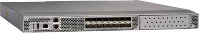
Cisco MDS 9132T 32-Gb Fiber Channel Switch
The next-generation Cisco® MDS 9132T 32-Gb 32-Port Fibre Channel Switch (Figure 14) provides high-speed Fibre Channel connectivity from the server rack to the SAN core. It empowers small, midsize, and large enterprises that are rapidly deploying cloud-scale applications using extremely dense virtualized servers, providing the dual benefits of greater bandwidth and consolidation.
Small-scale SAN architectures can be built from the foundation using this low-cost, low-power, non-blocking, line-rate, and low-latency, bi-directional airflow capable, fixed standalone SAN switch connecting both storage and host ports.
Medium-size to large-scale SAN architectures built with SAN core directors can expand 32-Gb connectivity to the server rack using these switches either in switch mode or Network Port Virtualization (NPV) mode.
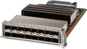
Additionally, investing in this switch for the lower-speed (4- or 8- or 16-Gb) server rack gives you the option to upgrade to 32-Gb server connectivity in the future using the 32-Gb Host Bus Adapter (HBA) that are available today. The Cisco® MDS 9132T 32-Gb 32-Port Fibre Channel switch also provides unmatched flexibility through a unique port expansion module (Figure 15) that provides a robust cost-effective, field swappable, port upgrade option.
This switch also offers state-of-the-art SAN analytics and telemetry capabilities that have been built into this next-generation hardware platform. This new state-of-the-art technology couples the next-generation port ASIC with a fully dedicated Network Processing Unit designed to complete analytics calculations in real time. The telemetry data extracted from the inspection of the frame headers are calculated on board (within the switch) and, using an industry-leading open format, can be streamed to any analytics-visualization platform. This switch also includes a dedicated 10/100/1000BASE-T telemetry port to maximize data delivery to any telemetry receiver including Cisco Data Center Network Manager.
· Features
- High performance: MDS 9132T architecture, with chip-integrated nonblocking arbitration, provides consistent 32-Gb low-latency performance across all traffic conditions for every Fibre Channel port on the switch.
- Capital Expenditure (CapEx) savings: The 32-Gb ports allow users to deploy them on existing 16- or 8-Gb transceivers, reducing initial CapEx with an option to upgrade to 32-Gb transceivers and adapters in the future.
- High availability: MDS 9132T switches continue to provide the same outstanding availability and reliability as the previous-generation Cisco MDS 9000 Family switches by providing optional redundancy on all major components such as the power supply and fan. Dual power supplies also facilitate redundant power grids.
- Pay-as-you-grow: The MDS 9132T Fibre Channel switch provides an option to deploy as few as eight 32-Gb Fibre Channel ports in the entry-level variant, which can grow by 8 ports to 16 ports, and thereafter with a port expansion module with sixteen 32-Gb ports, to up to 32 ports. This approach results in lower initial investment and power consumption for entry-level configurations of up to 16 ports compared to a fully loaded switch. Upgrading through an expansion module also reduces the overhead of managing multiple instances of port activation licenses on the switch. This unique combination of port upgrade options allows four possible configurations of 8 ports, 16 ports, 24 ports and 32 ports.
- Next-generation Application-Specific Integrated Circuit (ASIC): The MDS 9132T Fibre Channel switch is powered by the same high-performance 32-Gb Cisco ASIC with an integrated network processor that powers the Cisco MDS 9700 48-Port 32-Gb Fibre Channel Switching Module. Among all the advanced features that this ASIC enables, one of the most notable is inspection of Fibre Channel and Small Computer System Interface (SCSI) headers at wire speed on every flow in the smallest form-factor Fibre Channel switch without the need for any external taps or appliances. The recorded flows can be analyzed on the switch and also exported using a dedicated 10/100/1000BASE-T port for telemetry and analytics purposes.
- Intelligent network services: Slow-drain detection and isolation, VSAN technology, Access Control Lists (ACLs) for hardware-based intelligent frame processing, smartzoning and fabric wide Quality of Service (QoS) enable migration from SAN islands to enterprise wide storage networks. Traffic encryption is optionally available to meet stringent security requirements.
- Sophisticated diagnostics: The MDS 9132T provides intelligent diagnostics tools such as Inter-Switch Link (ISL) diagnostics, read diagnostic parameters, protocol decoding, network analysis tools, and integrated Cisco Call Home capability for greater reliability, faster problem resolution, and reduced service costs.
- Virtual machine awareness: The MDS 9132T provides visibility into all virtual machines logged into the fabric. This feature is available through HBAs capable of priority tagging the Virtual Machine Identifier (VMID) on every FC frame. Virtual machine awareness can be extended to intelligent fabric services such as analytics(1) to visualize performance of every flow originating from each virtual machine in the fabric.
- Programmable fabric: The MDS 9132T provides powerful Representational State Transfer (REST) and Cisco NX-API capabilities to enable flexible and rapid programming of utilities for the SAN as well as polling point-in-time telemetry data from any external tool.
- Single-pane management: The MDS 9132T can be provisioned, managed, monitored, and troubleshot using Cisco Data Center Network Manager (DCNM), which currently manages the entire suite of Cisco data center products.
- Self-contained advanced anticounterfeiting technology: The MDS 9132T uses on-board hardware that protects the entire system from malicious attacks by securing access to critical components such as the bootloader, system image loader and Joint Test Action Group (JTAG) interface.
Hypervisor
This Cisco Validated Design includes VMware vSphere 6.7 Update 3.
VMware vSphere 6.7
VMware provides virtualization software. VMware’s enterprise software hypervisors for servers VMware vSphere ESX, vSphere ESXi, and vSphere—are bare-metal hypervisors that run directly on server hardware without requiring an additional underlying operating system. VMware vCenter Server for vSphere provides central management and complete control and visibility into clusters, hosts, virtual machines, storage, networking, and other critical elements of your virtual infrastructure.
VMware vSphere 6.7 introduces many enhancements to vSphere Hypervisor, VMware virtual machines, vCenter Server, virtual storage, and virtual networking, further extending the core capabilities of the vSphere platform.
Now VMware announced vSphere 6.7, which is one of the most feature rich releases of vSphere in quite some time. The vCenter Server Appliance is taking charge in this release with several new features which we’ll cover in this blog article. For starters, the installer has gotten an overhaul with a new modern look and feel. Users of both Linux and Mac will also be ecstatic since the installer is now supported on those platforms along with Microsoft Windows. If that wasn’t enough, the vCenter Server Appliance now has features that are exclusive such as:
· Migration
· Improved Appliance Management
· VMware Update Manager
· Native High Availability
· Built-in Backup / Restore
VMware vSphere Client
With VMware vSphere 6.7, a fully supported version of the HTML5-based vSphere Client that will run alongside the vSphere Web Client. The vSphere Client is built into vCenter Server 6.7 (both Windows and Appliance) and is enabled by default. While the HTML-5 based vSphere, Client does not have full feature parity, the team has prioritized many of the day-to-day tasks of administrators and continue to seek feedback on items that will enable customers to use it full time. The vSphere Web Client continues to be accessible through “http://<vcenter_fqdn>/vsphere-client” while the vSphere Client is reachable through “http://<vcenter_fqdn>/ui”. VMware is periodically updating the vSphere Client outside of the normal vCenter Server release cycle. To make sure it is easy and simple for customers to stay up to date the vSphere Client will be able to be updated without any effects to the rest of vCenter Server.
Some of the benefits of the new vSphere Client are as follows:
· Clean, consistent UI built on VMware’s new Clarity UI standards (to be adopted across our portfolio)
· Built on HTML5 so it is truly a cross-browser and cross-platform application
· No browser plugins to install/manage
· Integrated into vCenter Server for 6.7 and fully supported
· Fully supports Enhanced Linked Mode
· Users of the Fling have been extremely positive about its performance
VMware ESXi 6.7 Hypervisor
VMware vSphere 6.7 introduces the following new features in the hypervisor:
· Scalability Improvements
- ESXi 6.7 dramatically increases the scalability of the platform. With vSphere Hypervisor 6.0, clusters can scale to as many as 64 hosts, up from 32 in previous releases. With 64 hosts in a cluster, vSphere 6.0 can support 8000 virtual machines in a single cluster. This capability enables greater consolidation ratios, more efficient use of VMware vSphere Distributed Resource Scheduler (DRS), and fewer clusters that must be separately managed. Each vSphere Hypervisor 6.7 instance can support up to 480 logical CPUs, 12 terabytes (TB) of RAM, and 1024 virtual machines. By using the newest hardware advances, ESXi 6.7 enables the virtualization of applications that previously had been thought to be non-virtualizable.
· ESXI 6.7 Security Enhancements
- Account management: ESXi 6.7 enables management of local accounts on the ESXi server using new ESXi CLI commands. The capability to add, list, remove, and modify accounts across all hosts in a cluster can be centrally managed using a vCenter Server system. Previously, the account and permission management functions for ESXi hosts were available only for direct host connections. The setup, removal, and listing of local permissions on ESXi servers can also be centrally managed.
- Account lockout: ESXi Host Advanced System Settings have two new options for the management of failed local account login attempts and account lockout duration. These parameters affect Secure Shell (SSH) and vSphere Web Services connections, but not ESXi direct console user interface (DCUI) or console shell access.
- Password complexity rules: In previous versions of ESXi, password complexity changes had to be made by manually editing the /etc/pam.d/passwd file on each ESXi host. In vSphere 6.0, an entry in Host Advanced System Settings enables changes to be centrally managed for all hosts in a cluster.
- Improved auditability of ESXi administrator actions: Prior to vSphere 6.0, actions at the vCenter Server level by a named user appeared in ESXi logs with the vpxuser username: for example, [user=vpxuser]. In vSphere 6.7, all actions at the vCenter Server level for an ESXi server appear in the ESXi logs with the vCenter Server username: for example, [user=vpxuser: DOMAIN\User]. This approach provides a better audit trail for actions run on a vCenter Server instance that conducted corresponding tasks on the ESXi hosts.
- Flexible lockdown modes: Prior to vSphere 6.7, only one lockdown mode was available. Feedback from customers indicated that this lockdown mode was inflexible in some use cases. With vSphere 6.7, two lockdown modes are available:
§ In normal lockdown mode, DCUI access is not stopped, and users on the DCUI access list can access the DCUI.
§ In strict lockdown mode, the DCUI is stopped.
§ Exception users: vSphere 6.0 offers a new function called exception users. Exception users are local accounts or Microsoft Active Directory accounts with permissions defined locally on the host to which these users have host access. These exception users are not recommended for general user accounts, but they are recommended for use by third-party applications—for service accounts, for example—that need host access when either normal or strict lockdown mode is enabled. Permissions on these accounts should be set to the bare minimum required for the application to perform its task and with an account that needs only read-only permissions on the ESXi host.
- Smart card authentication to DCUI: This function is for U.S. federal customers only. It enables DCUI login access using a Common Access Card (CAC) and Personal Identity Verification (PIV). The ESXi host must be part of an Active Directory domain.
What’s New in Update 3?
The following are the new features in Update 3:
· vCenter Server 6.7 Update 3 supports a dynamic relationship between the IP address settings of a vCenter Server Appliance and a DNS server by using the Dynamic Domain Name Service (DDNS). The DDNS client in the appliance automatically sends secure updates to DDNS servers on scheduled intervals.
· With vCenter Server 6.7 Update 3, you can configure virtual machines and templates with up to four NVIDIA virtual GPU (vGPU) devices to cover use cases requiring multiple GPU accelerators attached to a virtual machine. To use the vMotion vGPU feature, you must set the vgpu.hotmigrate.enabled advanced setting to true and make sure that both your vCenter Server and ESXi hosts are running vSphere 6.7 Update 3.
· vMotion of multi GPU-accelerated virtual machines might fail gracefully under heavy GPU workload due to the maximum switchover time of 100 secs. To avoid this failure, either increase the maximum allowable switchover time or wait until the virtual machine is performing a less intensive GPU workload.
· With vCenter Server 6.7 Update 3, you can change the Primary Network Identifier (PNID) of your vCenter Server Appliance. You can change the vCenter Server Appliance FQDN or host name, and also modify the IP address configuration of the virtual machine Management Network (NIC 0). For more information, see this VMware blog post.
· With vCenter Server 6.7 Update 3, if the overall health status of a vSAN cluster is Red, APIs to configure or extend HCI clusters throw InvalidState exception to prevent further configuration or extension. This fix aims to resolve situations when mixed versions of ESXi host in an HCI cluster might cause vSAN network partition.
· vCenter Server 6.7 adds new SandyBridge microcode to the cpu-microcode VIB to bring SandyBridge security up to par with other CPUs and fix per-VM Enhanced vMotion Compatibility (EVC) support. For more information, see VMware knowledge base article 1003212.
Desktop Broker
This Cisco Validated Design includes Citrix Virtual Apps and Desktops 7.15 LTSR.
Citrix Virtual Apps and Desktops 7.15
Enterprise IT organizations are tasked with the challenge of provisioning Microsoft Windows apps and desktops while managing cost, centralizing control, and enforcing the corporate security policy. Deploying Windows apps to users in any location, regardless of the device type and available network bandwidth, enables a mobile workforce that can improve productivity. With Citrix Virtual Apps and Desktops 7.15, IT can effectively control app and desktop provisioning while securing data assets and lowering capital and operating expenses.
The Citrix Virtual Apps and Desktops 7.15 release offers these benefits:
· Comprehensive virtual desktop delivery for any use case. The Citrix Virtual Apps and Desktops 7.15 release incorporates the full power of XenApp, delivering full desktops or just applications to users. Administrators can deploy both XenApp published applications and desktops (to maximize IT control at low cost) or personalized VDI desktops (with simplified image management) from the same management console. Citrix Virtual Apps and Desktops 7.15 leverages common policies and cohesive tools to govern both infrastructure resources and user access.
· Simplified support and choice of BYO (Bring Your Own) devices. Citrix Virtual Apps and Desktops 7.15 brings thousands of corporate Microsoft Windows-based applications to mobile devices with a native-touch experience and optimized performance. HDX technologies create a “high definition” user experience, even for graphics intensive design and engineering applications.
· Lower cost and complexity of application and desktop management. Citrix Virtual Apps and Desktops 7.15 helps IT organizations take advantage of agile and cost-effective cloud offerings, allowing the virtualized infrastructure to flex and meet seasonal demands or the need for sudden capacity changes. IT organizations can deploy Citrix Virtual Apps and Desktops application and desktop workloads to private or public clouds.
· Protection of sensitive information through centralization. Citrix Virtual Apps and Desktops decreases the risk of corporate data loss, enabling access while securing intellectual property and centralizing applications since assets reside in the data center.
· Virtual Delivery Agent improvements. Universal print server and driver enhancements and support for the HDX 3D Pro graphics acceleration for Windows 10 are key additions in Citrix Virtual Apps and Desktops 7.15.
· Improved high-definition user experience. Citrix Virtual Apps and Desktops 7.15 continues the evolutionary display protocol leadership with enhanced Thinwire display remoting protocol and Framehawk support for HDX 3D Pro.
Citrix Virtual Apps and Desktops are application and desktop virtualization solutions built on a unified architecture so they're simple to manage and flexible enough to meet the needs of all your organization's users. Citrix Virtual Apps and Desktops have a common set of management tools that simplify and automate IT tasks. You use the same architecture and management tools to manage public, private, and hybrid cloud deployments as you do for on premises deployments.
Citrix Virtual Apps and Desktops delivers:
· XenApp published apps, also known as server-based hosted applications: These are applications hosted from Microsoft Windows servers to any type of device, including Windows PCs, Macs, smartphones, and tablets. Some XenApp editions include technologies that further optimize the experience of using Windows applications on a mobile device by automatically translating native mobile-device display, navigation, and controls to Windows applications; enhancing performance over mobile networks; and enabling developers to optimize any custom Windows application for any mobile environment.
· XenApp published desktops, also known as server-hosted desktops: These are inexpensive, locked-down Windows virtual desktops hosted from Windows server operating systems. They are well suited for users, such as call center employees, who perform a standard set of tasks.
· Virtual machine–hosted apps: These are applications hosted from machines running Windows desktop operating systems for applications that can’t be hosted in a server environment.
· Windows applications delivered with Microsoft App-V: These applications use the same management tools that you use for the rest of your XenApp deployment.
· Citrix Virtual Apps and Desktops: Includes significant enhancements to help customers deliver Windows apps and desktops as mobile services while addressing management complexity and associated costs. Enhancements in this release include:
· Unified product architecture for Citrix Virtual Apps and Desktops: The FlexCast Management Architecture (FMA). This release supplies a single set of administrative interfaces to deliver both hosted-shared applications (RDS) and complete virtual desktops (VDI). Unlike earlier releases that separately provisioned Citrix Virtual Apps and Desktops farms, the Citrix Virtual Apps and Desktops 7.15 release allows administrators to deploy a single infrastructure and use a consistent set of tools to manage mixed application and desktop workloads.
· Support for extending deployments to the cloud. This release provides the ability for hybrid cloud provisioning from Microsoft Azure, Amazon Web Services (AWS) or any Cloud Platform-powered public or private cloud. Cloud deployments are configured, managed, and monitored through the same administrative consoles as deployments on traditional on-premises infrastructure.
Citrix Virtual Apps and Desktops delivers:
· VDI desktops: These virtual desktops each run a Microsoft Windows desktop operating system rather than running in a shared, server-based environment. They can provide users with their own desktops that they can fully personalize.
· Hosted physical desktops: This solution is well suited for providing secure access to powerful physical machines, such as blade servers, from within your data center.
· Remote PC access: This solution allows users to log in to their physical Windows PC from anywhere over a secure Citrix Virtual Apps and Desktops connection.
· Server VDI: This solution is designed to provide hosted desktops in multitenant, cloud environments.
· Capabilities that allow users to continue to use their virtual desktops: These capabilities let users continue to work while not connected to your network.
This product release includes the following new and enhanced features:
Zones
Deployments that span widely-dispersed locations connected by a WAN can face challenges due to network latency and reliability. Configuring zones can help users in remote regions connect to local resources without forcing connections to traverse large segments of the WAN. Using zones allows effective Site management from a single Citrix Studio console, Citrix Director, and the Site database. This saves the costs of deploying, staffing, licensing, and maintaining additional Sites containing separate databases in remote locations.
Zones can be helpful in deployments of all sizes. You can use zones to keep applications and desktops closer to end users, which improves performance.
Improved Database Flow and Configuration
When you configure the databases during Site creation, you can now specify separate locations for the Site, Logging, and Monitoring databases. Later, you can specify different locations for all three databases. In previous releases, all three databases were created at the same address, and you could not specify a different address for the Site database later.
You can now add more Delivery Controllers when you create a Site, as well as later. In previous releases, you could add more Controllers only after you created the Site.
Application Limits
Configure application limits to help manage application use. For example, you can use application limits to manage the number of users accessing an application simultaneously. Similarly, application limits can be used to manage the number of simultaneous instances of resource-intensive applications, this can help maintain server performance and prevent deterioration in service.
For more information, see the Manage applications article.
Multiple Notifications before Machine Updates or Scheduled Restarts
You can now choose to repeat a notification message that is sent to affected machines before the following types of actions begin:
· Updating machines in a Machine Catalog using a new master image
· Restarting machines in a Delivery Group according to a configured schedule
If you indicate that the first message should be sent to each affected machine 15 minutes before the update or restart begins, you can also specify that the message is repeated every five minutes until the update/restart begins.
For more information, see the Manage Machine Catalogs and Manage Delivery Groups articles.
API Support for Managing Session Roaming
By default, sessions roam between client devices with the user. When the user launches a session and then moves to another device, the same session is used, and applications are available on both devices. The applications follow, regardless of the device or whether current sessions exist. Similarly, printers and other resources assigned to the application follow.
![]() You can now use the PowerShell SDK to tailor session roaming. This was an experimental feature in the previous release.
You can now use the PowerShell SDK to tailor session roaming. This was an experimental feature in the previous release.
For more information, see the Sessions article.
API Support for Provisioning Virtual Machines from Hypervisor Templates
When using the PowerShell SDK to create or update a Machine Catalog, you can now select a template from other hypervisor connections. This is in addition to the currently-available choices of virtual machine images and snapshots.
Support for New and Additional Platforms
![]() See the System requirements article for full support information. Information about support for third-party product versions is updated periodically.
See the System requirements article for full support information. Information about support for third-party product versions is updated periodically.
By default, SQL Server 2014 SP2 Express is installed when installing the Controller if an existing supported SQL Server installation is not detected.
You can install Studio or VDAs for Windows Desktop OS on machines running Windows 10.
You can create connections to Microsoft Azure virtualization resources.
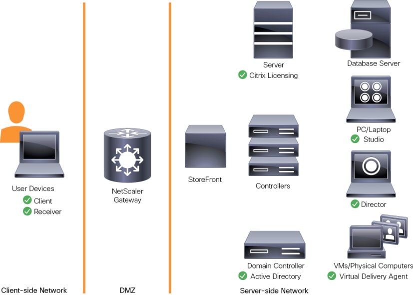
Citrix Provisioning Services 7.15
Most enterprises struggle to keep up with the proliferation and management of computers in their environments. Each computer, whether it is a desktop PC, a server in a data center, or a kiosk-type device, must be managed as an individual entity. The benefits of distributed processing come at the cost of distributed management. It costs time and money to set up, update, support, and ultimately decommission each computer. The initial cost of the machine is often dwarfed by operating costs.
Citrix PVS takes a very different approach from traditional imaging solutions by fundamentally changing the relationship between hardware and the software that runs on it. By streaming a single shared disk image (vDisk) rather than copying images to individual machines, PVS enables organizations to reduce the number of disk images that they manage, even as the number of machines continues to grow, simultaneously providing the efficiency of centralized management and the benefits of distributed processing.
In addition, because machines are streaming disk data dynamically and in real time from a single shared image, machine image consistency is essentially ensured. At the same time, the configuration, applications, and even the OS of large pools of machines can be completed changed in the time it takes the machines to reboot.
Using PVS, any vDisk can be configured in standard-image mode. A vDisk in standard-image mode allows many computers to boot from it simultaneously, greatly reducing the number of images that must be maintained and the amount of storage that is required. The vDisk is in read-only format, and the image cannot be changed by target devices.
Benefits for Citrix Virtual Apps and Desktops and Other Server Farm Administrators
If you manage a pool of servers that work as a farm, such as Citrix Virtual Apps and Desktops servers or web servers, maintaining a uniform patch level on your servers can be difficult and time consuming. With traditional imaging solutions, you start with a clean golden master image, but as soon as a server is built with the master image, you must patch that individual server along with all the other individual servers. Rolling out patches to individual servers in your farm is not only inefficient, but the results can also be unreliable. Patches often fail on an individual server, and you may not realize you have a problem until users start complaining or the server has an outage. After that happens, getting the server resynchronized with the rest of the farm can be challenging, and sometimes a full reimaging of the machine is required.
With Citrix PVS, patch management for server farms is simple and reliable. You start by managing your golden image, and you continue to manage that single golden image. All patching is performed in one place and then streamed to your servers when they boot. Server build consistency is assured because all your servers use a single shared copy of the disk image. If a server becomes corrupted, simply reboot it, and it is instantly back to the known good state of your master image. Upgrades are extremely fast to implement. After you have your updated image ready for production, you simply assign the new image version to the servers and reboot them. You can deploy the new image to any number of servers in the time it takes them to reboot. Just as important, rollback can be performed in the same way, so problems with new images do not need to take your servers or your users out of commission for an extended period of time.
Benefits for Desktop Administrators
Because Citrix PVS is part of Citrix Virtual Apps and Desktops, desktop administrators can use PVS’s streaming technology to simplify, consolidate, and reduce the costs of both physical and virtual desktop delivery. Many organizations are beginning to explore desktop virtualization. Although virtualization addresses many of IT’s needs for consolidation and simplified management, deploying it also requires the deployment of supporting infrastructure. Without PVS, storage costs can make desktop virtualization too costly for the IT budget. However, with PVS, IT can reduce the amount of storage required for VDI by as much as 90 percent. And with a single image to manage instead of hundreds or thousands of desktops, PVS significantly reduces the cost, effort, and complexity for desktop administration.
Different types of workers across the enterprise need different types of desktops. Some require simplicity and standardization, and others require high performance and personalization. Citrix Virtual Apps and Desktops can meet these requirements in a single solution using Citrix FlexCast delivery technology. With FlexCast, IT can deliver every type of virtual desktop, each specifically tailored to meet the performance, security, and flexibility requirements of each individual user.
Not all desktops applications can be supported by virtual desktops. For these scenarios, IT can still reap the benefits of consolidation and single-image management. Desktop images are stored and managed centrally in the data center and streamed to physical desktops on demand. This model works particularly well for standardized desktops such as those in lab and training environments and call centers and thin-client devices used to access virtual desktops.
What’s New in Cumulative Update 4(CU4)?
The following are the new features found in CU4:
· When you upgrade Delivery Controllers and a site to 7.15 CU4, preliminary site tests run before the actual upgrade begins. These tests include verification that essential Citrix services are running properly, and that the site database is operating correctly and has been recently backed up. After the tests run, you can view a report. Then, you can fix any issues that were detected and optionally run the tests again. This helps ensure that the upgrade will proceed successfully.
· This release removes the dependency on Version 2.0 of PowerShell in stand-alone deployments of Citrix Studio and its components.
· If the installation of a VDA or a Delivery Controller fails, an MSI analyzer parses the failing MSI log, displaying the exact error code. The analyzer suggests a CTX article if it’s a known issue. The analyzer also collects anonymized data about the failure error code. This data is included with other data collected by CEIP. If you end enrollment in CEIP, the collected MSI analyzer data is no longer sent to Citrix.
Citrix Provisioning Services Solution
Citrix PVS streaming technology allows computers to be provisioned and re-provisioned in real time from a single shared disk image. With this approach, administrators can completely eliminate the need to manage and patch individual systems. Instead, all image management is performed on the master image. The local hard drive of each system can be used for runtime data caching or, in some scenarios, removed from the system entirely, which reduces power use, system failure rate, and security risk.
The PVS solution’s infrastructure is based on software-streaming technology. After PVS components are installed and configured, a vDisk is created from a device’s hard drive by taking a snapshot of the OS and application image and then storing that image as a vDisk file on the network. A device used for this process is referred to as a master target device. The devices that use the vDisks are called target devices. vDisks can exist on a PVS, file share, or in larger deployments, on a storage system with which PVS can communicate (iSCSI, SAN, network-attached storage [NAS], and Common Internet File System [CIFS]). vDisks can be assigned to a single target device in private-image mode, or to multiple target devices in standard-image mode.
Citrix Provisioning Services Infrastructure
The Citrix PVS infrastructure design directly relates to administrative roles within a PVS farm. The PVS administrator role determines which components that an administrator can manage or view in the console.
A PVS farm contains several components. Figure 17 illustrates a high-level view of a basic PVS infrastructure and shows how PVS components might appear within that implementation.
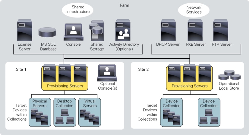
The following new features are available with Provisioning Services 7.15:
· Linux streaming
· XenServer proxy using PVS-Accelerator
Purity for FlashArray
At the heart of every FlashArray is Purity Operating Environment software. Purity implements advanced data reduction, storage management, and flash management features, enabling organizations to enjoy Tier 1 data services for all workloads, proven 99.9999% availability over two years (inclusive of maintenance and generational upgrades), completely non-disruptive operations, 2X better data reduction versus alternative all-flash solutions, and, with FlashArray//X, the power and efficiency of DirectFlash™. Moreover, Purity includes enterprise-grade data security, modern data protection options, and complete business continuity and global disaster recovery through ActiveCluster multi-site stretch cluster and ActiveDR* for continuous replication with near zero RPO. All these features are included with every array.
FlashArray//X Specifications
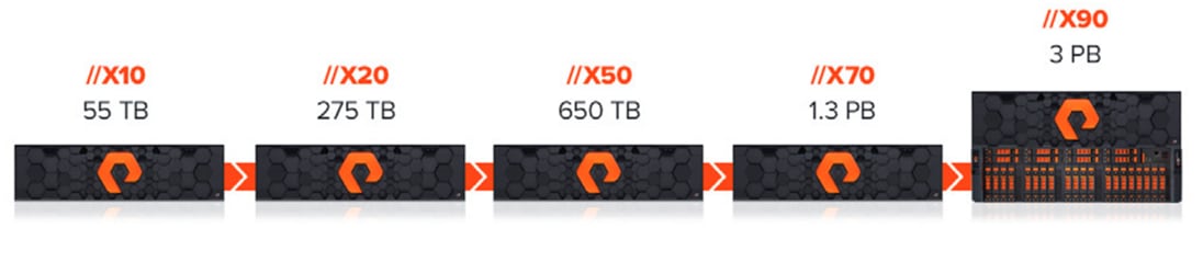
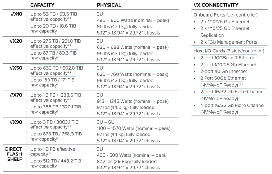
* Stated //X specifications are applicable to //X R2 versions, //X R3 specs are also available here
** Effective capacity assumes HA, RAID, and metadata overhead, GB-to-GiB conversion, and includes the benefit of data reduction with always-on inline deduplication, compression, and pattern removal. Average data reduction is calculated at 5-to-1 and does not include thin provisioning or snapshots.
*** FlashArray //X currently supports NVMe/RoCE with a roadmap for NVMe/FC and NVMe/TCP.
Customers can deploy storage once and enjoy a subscription to continuous innovation through Pure’s Evergreen Storage ownership model: expand and improve performance, capacity, density, and/or features for 10 years or more – all without downtime, performance impact, or data migrations. Pure has disrupted the industry’s 3-5-year rip-and-replace cycle by engineering compatibility for future technologies right into its products, notably nondisruptive capability to upgrade from //M to //X with NVMe, DirectMemory, and NVMe-oF capability.
Pure1®
Pure1, our cloud-based management, analytics, and support platform, expands the self-managing, plug-n-play design of Pure all-flash arrays with the machine learning predictive analytics and continuous scanning of Pure1 Meta™ to enable an effortless, worry-free data platform.
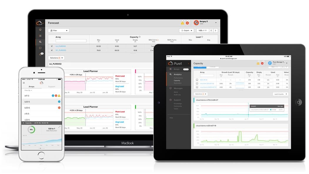
Pure1 Manage
In the Cloud IT operating model, installing and deploying management software is an oxymoron: you simply login. Pure1 Manage is SaaS-based, allowing you to manage your array from any browser or from the Pure1 Mobile App, with nothing extra to purchase, deploy, or maintain. From a single dashboard you can manage all your arrays, with full visibility on the health and performance of your storage.
Pure1 Analyze
Pure1 Analyze delivers true performance forecasting – giving customers complete visibility into the performance and capacity needs of their array, now and in the future. Performance forecasting enables intelligent consolidation and unprecedented workload optimization.
Pure1 Support
Pure combines an ultra-proactive support team with the predictive intelligence of Pure1 Meta to deliver unrivaled support that’s a key component in our proven FlashArray 99.9999% availability. Customers are often surprised and delighted when we fix issues they did not even know existed.
Pure1 META
The foundation of Pure1 services, Pure1 Meta is global intelligence built from a massive collection of storage array health and performance data. By continuously scanning call-home telemetry from Pure’s installed base, Pure1 Meta uses machine learning predictive analytics to help resolve potential issues and optimize workloads. The result is both a white glove customer support experience and breakthrough capabilities like accurate performance forecasting.
Meta is always expanding and refining what it knows about array performance and health, moving the Data Platform toward a future of self-driving storage.
Pure1 VM Analytics
Pure1 helps you narrow down the troubleshooting steps in your virtualized environment. VM Analytics provides you with a visual representation of the IO path from the VM all the way through to the FlashArray. Other tools and features guide you through identifying where an issue might be occurring in order to help eliminate potential candidates for a problem.
VM Analytics doesn’t only help when there’s a problem. The visualization allows you to identify which volumes and arrays particular applications are running on. This brings the whole environment into a more manageable domain.
There are many reasons to consider a virtual desktop solution such as an ever growing and diverse base of user devices, complexity in management of traditional desktops, security, and even Bring Your Own Device (BYOD) to work programs. The first step in designing a virtual desktop solution is to understand the user community and the type of tasks that are required to successfully execute their role. The following user classifications are provided:
· Knowledge Workers today do not just work in their offices all day – they attend meetings, visit branch offices, work from home, and even coffee shops. These anywhere workers expect access to all of their same applications and data wherever they are.
· External Contractors are increasingly part of your everyday business. They need access to certain portions of your applications and data, yet administrators still have little control over the devices they use and the locations they work from. Consequently, IT is stuck making trade-offs on the cost of providing these workers a device vs. the security risk of allowing them access from their own devices.
· Task Workers perform a set of well-defined tasks. These workers access a small set of applications and have limited requirements from their PCs. However, since these workers are interacting with your customers, partners, and employees, they have access to your most critical data.
· Mobile Workers need access to their virtual desktop from everywhere, regardless of their ability to connect to a network. In addition, these workers expect the ability to personalize their PCs, by installing their own applications and storing their own data, such as photos and music, on these devices.
· Shared Workstation users are often found in state-of-the-art university and business computer labs, conference rooms or training centers. Shared workstation environments have the constant requirement to re-provision desktops with the latest operating systems and applications as the needs of the organization change, tops the list.
After the user classifications have been identified and the business requirements for each user classification have been defined, it becomes essential to evaluate the types of virtual desktops that are needed based on user requirements. There are essentially five potential desktops environments for each user:
· Traditional PC: A traditional PC is what typically constitutes a desktop environment: physical device with a locally installed operating system.
· Hosted Shared Desktop: A hosted, server-based desktop is a desktop where the user interacts through a delivery protocol. With hosted, server-based desktops, a single installed instance of a server operating system, such as Microsoft Windows Server 2019, is shared by multiple users simultaneously. Each user receives a desktop "session" and works in an isolated memory space. Remoted Desktop Server Hosted Server sessions: A hosted virtual desktop is a virtual desktop running on a virtualization layer (ESX). The user does not work with and sit in front of the desktop, but instead the user interacts through a delivery protocol.
· Published Applications: Published applications run entirely on the Citrix Virtual Apps and Desktops server virtual machines and the user interacts through a delivery protocol. With published applications, a single installed instance of an application, such as Microsoft Office, is shared by multiple users simultaneously. Each user receives an application "session" and works in an isolated memory space.
· Streamed Applications: Streamed desktops and applications run entirely on the user‘s local client device and are sent from a server on demand. The user interacts with the application or desktop directly, but the resources may only available while they are connected to the network.
· Local Virtual Desktop: A local virtual desktop is a desktop running entirely on the user‘s local device and continues to operate when disconnected from the network. In this case, the user’s local device is used as a type 1 hypervisor and is synced with the data center when the device is connected to the network.
Understanding Applications and Data
When the desktop user groups and sub-groups have been identified, the next task is to catalog group application and data requirements. This can be one of the most time-consuming processes in the VDI planning exercise but is essential for the VDI project’s success. If the applications and data are not identified and co-located, performance will be negatively affected.
The process of analyzing the variety of application and data pairs for an organization will likely be complicated by the inclusion cloud applications, for example, SalesForce.com. This application and data analysis is beyond the scope of this Cisco Validated Design but should not be omitted from the planning process. There are a variety of third-party tools available to assist organizations with this crucial exercise.
Project Planning and Solution Sizing Sample Questions
Now that user groups, their applications and their data requirements are understood, some key project and solution sizing questions may be considered.
General project questions should be addressed at the outset, including:
· Has a VDI pilot plan been created based on the business analysis of the desktop groups, applications, and data?
· Is there infrastructure and budget in place to run the pilot program?
· Are the required skill sets to execute the VDI project available? Can we hire or contract for them?
· Do we have end user experience performance metrics identified for each desktop sub-group?
· How will we measure success or failure?
· What is the future implication of success or failure?
Below is a non-exhaustive list of sizing questions that should be addressed for each user sub-group:
· What is the desktop OS planned? Windows 8 or Windows 10?
· 32 bit or 64 bit desktop OS?
· How many virtual desktops will be deployed in the pilot? In production? All Windows 8/10?
· How much memory per target desktop group desktop?
· Are there any rich media, Flash, or graphics-intensive workloads?
· Are there any applications installed? What application delivery methods will be used, Installed, Streamed, Layered, Hosted, or Local?
· What is the desktop OS planned for HSD Server Roles? Windows server 2016 or Server 2019?
· What is the hypervisor for the solution?
· What is the storage configuration in the existing environment?
· Are there sufficient IOPS available for the write-intensive VDI workload?
· Will there be storage dedicated and tuned for VDI service?
· Is there a voice component to the desktop?
· Is anti-virus a part of the image?
· What is the SQL server version for database? SQL server 2016 or 2019?
· Is user profile management (for example, non-roaming profile based) part of the solution?
· What is the fault tolerance, failover, disaster recovery plan?
· Are there additional desktop sub-group specific questions?
Hypervisor Selection
VMware vSphere has been identified the hypervisor for both HSD Hosted Sessions and VDI based desktops:
· VMware vSphere: VMware vSphere comprises the management infrastructure or virtual center server software and the hypervisor software that virtualizes the hardware resources on the servers. It offers features like Distributed Resource Scheduler, vMotion, high availability, Storage vMotion, VMFS, and a multi-pathing storage layer. More information on vSphere can be obtained at the VMware website.
![]() For this CVD, the hypervisor used was VMware ESXi 6.7 Update 3.
For this CVD, the hypervisor used was VMware ESXi 6.7 Update 3.
Storage Considerations
Boot From SAN
When utilizing Cisco UCS Server technology it is recommended to configure Boot from SAN and store the boot partitions on remote storage, this enabled architects and administrators to take full advantage of the stateless nature of service profiles for hardware flexibility across lifecycle management of server hardware generational changes, Operating Systems/Hypervisors and overall portability of server identity. Boot from SAN also removes the need to populate local server storage creating more administrative overhead.
Pure Storage FlashArray Considerations
Make sure Each FlashArray Controller is connected to BOTH storage fabrics (A/B).
Within Purity, it’s best practice to map Hosts to Host Groups and then Host Groups to Volumes, this ensures the Volume is presented on the same LUN ID to all hosts and allows for simplified management of ESXi Clusters across multiple nodes.
How big should a Volume be? With the Purity Operating Environment, we remove the complexities of aggregates, RAID groups, and so on. When managing storage, you just create a volume based on the size required, availability and performance are taken care of through RAID-HD and DirectFlash Software. As an administrator you can create 1 10TB volume or 10 1TB Volumes and their performance/availability will be the same, so instead of creating volumes for availability or performance you can think about recoverability, manageability, and administrative considerations. For example, what data do I want to present to this application or what data do I want to store together so I can replicate it to another site/system/cloud, and so on.
Port Connectivity
With 10/25/40Gbe connectivity support, while both 10 and 25 Gbe is provided through 2 onboard NICs on each FlashArray controller, if more interfaces are required or if 40Gbe connectivity is also required, then make sure you have provisioned for additional NICs included in the original FlashArray BOM.
With 16/32Gb Fiber Channel support (N-2 support), Pure Storage offers up to 32Gb FC support on the latest FlashArray//X series arrays. Always make sure the correct number of HBAs and the speed of SFPs are included in the original FlashArray BOM.
Oversubscription
To reduce the impact of an outage or maintenance scheduled downtime, it’s good practice when designing fabrics to provide oversubscription of bandwidth; this enables a similar performance profile during component failure and protects workloads from being impacted by a reduced number of paths during a component failure or maintenance event. Oversubscription can be achieved by increasing the number of physically cabled connections between storage and compute. These connections can then be utilized to deliver performance and reduced latency to the underlying workloads running on the solution.
Topology
When configuring your SAN, it’s important to remember that the more hops you have, the more latency you will see. For best performance, the ideal topology is a “Flat Fabric” where the FlashArray is only one hop away from any applications it hosts.
VMware Virtual Volumes Considerations
When configuring a Pure Storage FlashArray with Virtual Volumes, the FlashArray will only be able to provide the VASA Service to an individual vCenter at this time. vCenters that are in Enhanced Linked Mode will be able to communicate with the same FlashArray, however vCenters that are not in Enhanced Linked Mode cannot both use VVols on the same FlashArray. Should multiple vCenters need to use the same FlashArray for VVols, they should be configured in Enhanced Linked Mode.
Ensure that the Config VVol is either part of an existing FlashArray Protection Group, Storage Policy that includes snapshots or manual snapshots of the Config VVol are taken. This will help with the virtual machine recovery process if the virtual machine is deleted.
Remember that there are some FlashArray limits on Volume Connections per Host, Volume Count and Snapshot Count. For more information about FlashArray limits, go to: https://support.purestorage.com/FlashArray/PurityFA/General_Troubleshooting/Pure_Storage_FlashArray_Limits
When a Storage Policy is applied to a VVol virtual machine, the Volumes associated with that virtual machine are added to the designated protection group when applying the policy to the virtual machine. Should replication be part of the policy, be mindful of the number of virtual machines using that storage policy and replication group. A high number of virtual machines with high change rate could cause replication to miss its schedule due to increases replication bandwidth and time needed to complete the scheduled snapshot. Pure Storage recommends VVol virtual machines that have Storage Policies applied be balanced between protection groups. Currently Pure Storage recommends 20 to 30 virtual machines per Storage Policy Replication Group.
Pure Storage FlashArray Best Practices for VMware vSphere
The following Pure Storage best practices for VMware vSphere should be followed as part of a design:
· For hosts earlier than 6.0 Patch 5 or 6.5 Update 1, Configure Round Robin, and an I/O Operations Limit of 1 for every FlashArray device. This is no longer needed for later versions of ESXi. The best way to do this is to create an ESXi SATP Rule on every host (below). This will make sure all devices are set automatically.
esxcli storage nmp satp rule add -s "VMW_SATP_ALUA" -V "PURE" -M "FlashArray" -P "VMW_PSP_RR" -O "iops=1"
· For iSCSI, disable DelayedAck and set the Login Timeout to 30 seconds. Jumbo Frames are optional.
· In vSphere 6.x, if hosts have any VMFS-5 volumes, change EnableBlockDelete to enabled. If it is all VMFS-6, this change is not needed.
· For VMFS-5, Run UNMAP frequently.
· For VMFS-6, keep automatic UNMAP enabled.
· When using vSphere Replication and/or when you have ESXi hosts running EFI-enabled virtual machines, set the ESXi parameter Disk.DiskMaxIOSize to 4 MB.
· DataMover.HardwareAcceleratedMove, DataMover.HardwareAcceleratedInit, and VMFS3.HardwareAcceleratedLocking should all be enabled.
· Ensure all ESXi hosts are connected to both FlashArray controllers. Ideally at least two paths to each. Aim for total redundancy.
· Install VMware tools whenever possible.
· Queue depths should be left at the default. Changing queue depths on the ESXi host is considered to be a tweak and should only be examined if a performance problem (high latency) is observed.
· When mounting snapshots, use the ESXi resignature option and avoid force-mounting.
· Configure Host Groups on the FlashArray identically to clusters in vSphere. For example, if a cluster has four hosts in it, create a corresponding Host Group on the relevant FlashArray with exactly those four hosts—no more, no less.
· Use Paravirtual SCSI adapters for virtual machines whenever possible.
· Atomic Test and Set (ATS) is required on all Pure Storage volumes. This is a default configuration and no changes should normally be needed.
· UseATSForHBOnVMFS5 should be enabled. This was introduced in vSphere 5.5 U2 and is enabled by default. It is NOT required though.
For more information about the VMware vSphere Pure Storage FlashArray Best Practices, go to:
Web Guide: FlashArray® VMware Best Practices
Citrix Virtual Apps and Desktops Design Fundamentals
An ever growing and diverse base of user devices, complexity in management of traditional desktops, security, and even Bring Your Own (BYO) device to work programs are prime reasons for moving to a virtual desktop solution.
Citrix Virtual Apps and Desktops 7.15 integrates Hosted Shared and VDI desktop virtualization technologies into a unified architecture that enables a scalable, simple, efficient, and manageable solution for delivering Windows applications and desktops as a service.
You can select applications from an easy-to-use “store” that is accessible from tablets, smartphones, PCs, Macs, and thin clients. Citrix Virtual Apps and Desktops delivers a native touch-optimized experience with HDX high-definition performance, even over mobile networks.
Machine Catalogs
Collections of identical virtual machines or physical computers are managed as a single entity called a Machine Catalog. In this CVD, virtual machine provisioning relies on Citrix Provisioning Services to make sure that the machines in the catalog are consistent. In this CVD, machines in the Machine Catalog are configured to run either a Windows Server OS (for RDS hosted shared desktops) or a Windows Desktop OS (for hosted pooled VDI desktops).
Delivery Groups
To deliver desktops and applications to users, you create a Machine Catalog and then allocate machines from the catalog to users by creating Delivery Groups. Delivery Groups provide desktops, applications, or a combination of desktops and applications to users. Creating a Delivery Group is a flexible way of allocating machines and applications to users. In a Delivery Group, you can:
· Use machines from multiple catalogs
· Allocate a user to multiple machines
· Allocate multiple users to one machine
As part of the creation process, you specify the following Delivery Group properties:
· Users, groups, and applications allocated to Delivery Groups
· Desktop settings to match users' needs
· Desktop power management options
Figure 18 illustrates how users access desktops and applications through machine catalogs and delivery groups.
![]() The Server OS and Desktop OS Machines configured in this CVD support the hosted shared desktops and hosted virtual desktops (both non-persistent and persistent).
The Server OS and Desktop OS Machines configured in this CVD support the hosted shared desktops and hosted virtual desktops (both non-persistent and persistent).
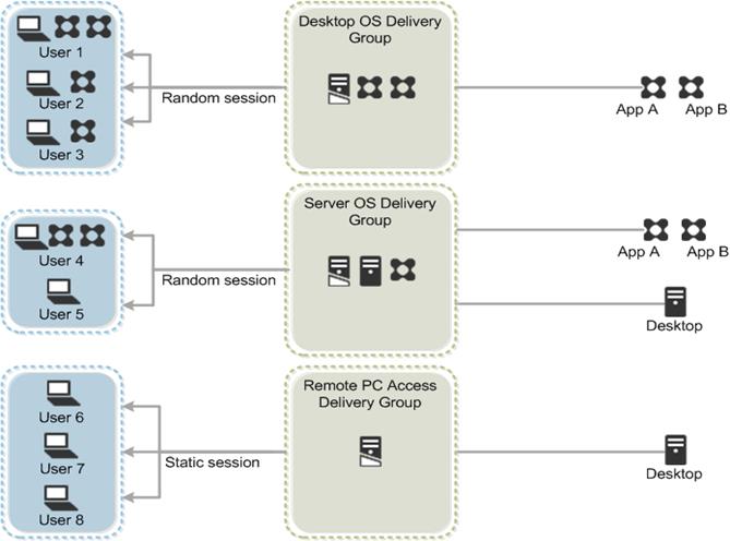
Citrix Provisioning Services
Citrix Virtual Apps and Desktops 7.15 can be deployed with or without Citrix Provisioning Services (PVS). The advantage of using Citrix PVS is that it allows virtual machines to be provisioned and re-provisioned in real-time from a single shared-disk image. In this way administrators can completely eliminate the need to manage and patch individual systems and reduce the number of disk images that they manage, even as the number of machines continues to grow, simultaneously providing the efficiencies of a centralized management with the benefits of distributed processing.
The Provisioning Services solution’s infrastructure is based on software-streaming technology. After installing and configuring Provisioning Services components, a single shared disk image (vDisk) is created from a device’s hard drive by taking a snapshot of the OS and application image, and then storing that image as a vDisk file on the network. A device that is used during the vDisk creation process is the Master target device. Devices or virtual machines that use the created vDisks are called target devices.
When a target device is turned on, it is set to boot from the network and to communicate with a Provisioning Server. Unlike thin-client technology, processing takes place on the target device.
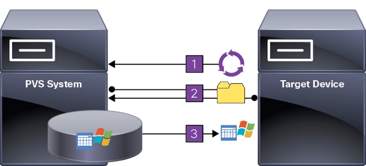
The target device downloads the boot file from a Provisioning Server (Step 2) and boots. Based on the boot configuration settings, the appropriate vDisk is mounted on the Provisioning Server (Step 3). The vDisk software is then streamed to the target device as needed, appearing as a regular hard drive to the system.
Instead of immediately pulling all the vDisk contents down to the target device (as with traditional imaging solutions), the data is brought across the network in real-time as needed. This approach allows a target device to get a completely new operating system and set of software in the time it takes to reboot. This approach dramatically decreases the amount of network bandwidth required and making it possible to support a larger number of target devices on a network without impacting performance
Citrix PVS can create desktops as Pooled or Private:
· Pooled Desktop: A pooled virtual desktop uses Citrix PVS to stream a standard desktop image to multiple desktop instances upon boot.
· Private Desktop: A private desktop is a single desktop assigned to one distinct user.
The alternative to Citrix Provisioning Services for pooled desktop deployments is Citrix Machine Creation Services (MCS), which is integrated with the Citrix Virtual Apps and Desktops Studio console.
Locate the PVS Write Cache
When considering a PVS deployment, there are some design decisions that need to be made regarding the write cache for the target devices that leverage provisioning services. The write cache is a cache of all data that the target device has written. If data is written to the PVS vDisk in a caching mode, the data is not written back to the base vDisk. Instead, it is written to a write cache file in one of the following locations:
· Cache on device hard drive. Write cache exists as a file in NTFS format, located on the target-device’s hard drive. This option frees up the Provisioning Server since it does not have to process write requests and does not have the finite limitation of RAM.
· Cache on device hard drive persisted. (Experimental Phase) This is the same as “Cache on device hard drive”, except that the cache persists. At this time, this method is an experimental feature only, and is only supported for NT6.1 or later (Windows 10 and Windows 2008 R2 and later). This method also requires a different bootstrap.
· Cache in device RAM. Write cache can exist as a temporary file in the target device’s RAM. This provides the fastest method of disk access since memory access is always faster than disk access.
· Cache in device RAM with overflow on hard disk. This method uses VHDX differencing format and is only available for Windows 10 and Server 2008 R2 and later. When RAM is zero, the target device write cache is only written to the local disk. When RAM is not zero, the target device write cache is written to RAM first. When RAM is full, the least recently used block of data is written to the local differencing disk to accommodate newer data on RAM. The amount of RAM specified is the non-paged kernel memory that the target device will consume.
· Cache on a server. Write cache can exist as a temporary file on a Provisioning Server. In this configuration, all writes are handled by the Provisioning Server, which can increase disk I/O and network traffic. For additional security, the Provisioning Server can be configured to encrypt write cache files. Since the write-cache file persists on the hard drive between reboots, encrypted data provides data protection in the event a hard drive is stolen.
· Cache on server persisted. This cache option allows for the saved changes between reboots. Using this option, a rebooted target device is able to retrieve changes made from previous sessions that differ from the read only vDisk image. If a vDisk is set to this method of caching, each target device that accesses the vDisk automatically has a device-specific, writable disk file created. Any changes made to the vDisk image are written to that file, which is not automatically deleted upon shutdown.
![]() In this CVD, Provisioning Server 7.15 was used to manage Pooled/Non-Persistent VDI Machines and XenApp RDS Machines with “Cache in device RAM with Overflow on Hard Disk” for each virtual machine. This design enables good scalability to many thousands of desktops. Provisioning Server 7.15 was used for Active Directory machine account creation and management as well as for streaming the shared disk to the hypervisor hosts.
In this CVD, Provisioning Server 7.15 was used to manage Pooled/Non-Persistent VDI Machines and XenApp RDS Machines with “Cache in device RAM with Overflow on Hard Disk” for each virtual machine. This design enables good scalability to many thousands of desktops. Provisioning Server 7.15 was used for Active Directory machine account creation and management as well as for streaming the shared disk to the hypervisor hosts.
Example Citrix Virtual Apps and Desktops Deployments
Two examples of typical Citrix Virtual Apps and Desktops deployments are as follows:
· A distributed components configuration
· A multiple site configuration
Since XenApp and Citrix Virtual Apps and Desktops 7.15 are based on a unified architecture, combined they can deliver a combination of Hosted Shared Desktops (HSDs, using a Server OS machine) and Hosted Virtual Desktops (HVDs, using a Desktop OS).
Distributed Components Configuration
You can distribute the components of your deployment among a greater number of servers or provide greater scalability and failover by increasing the number of controllers in your site. You can install management consoles on separate computers to manage the deployment remotely. A distributed deployment is necessary for an infrastructure based on remote access through NetScaler Gateway (formerly called Access Gateway).
Figure 20 shows an example of a distributed components configuration. A simplified version of this configuration is often deployed for an initial proof-of-concept (POC) deployment. This CVD deploys Citrix Virtual Apps and Desktops in a configuration that resembles this distributed component configuration shown. Two Cisco UCS B200M5 blade servers host the required infrastructure services (AD, DNS, DHCP, License Server, SQL, Citrix Virtual Apps and Desktops management, and StoreFront servers).
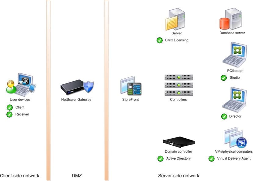
Multiple Site Configuration
If you have multiple regional sites, you can use Citrix NetScaler to direct user connections to the most appropriate site and StoreFront to deliver desktops and applications to users.
In Figure 21 depicting multiple sites, a site was created in two data centers. Having two sites globally, rather than just one, minimizes the amount of unnecessary WAN traffic.
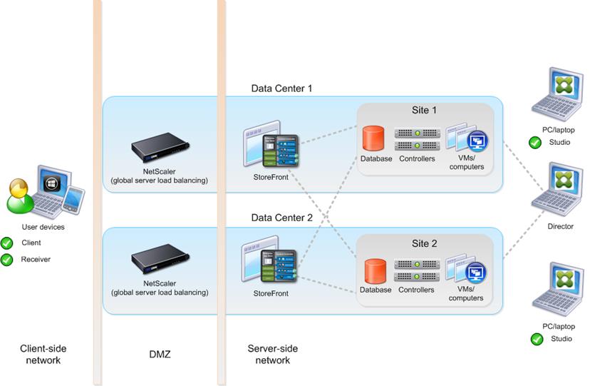
You can use StoreFront to aggregate resources from multiple sites to provide users with a single point of access with NetScaler. A separate Studio console is required to manage each site; sites cannot be managed as a single entity. You can use Director to support users across sites.
Citrix NetScaler accelerates application performance, load balances servers, increases security, and optimizes the user experience. In this example, two NetScalers are used to provide a high availability configuration. The NetScalers are configured for Global Server Load Balancing and positioned in the DMZ to provide a multi-site, fault-tolerant solution.
The CVD was done based on single site and did not use NetScaler for its infrastructure and testing.
Citrix Cloud Services
Easily deliver the Citrix portfolio of products as a service. Citrix Cloud services simplify the delivery and management of Citrix technologies extending existing on-premises software deployments and creating hybrid workspace services.
· Fast: Deploy apps and desktops, or complete secure digital workspaces in hours, not weeks.
· Adaptable: Choose to deploy on any cloud or virtual infrastructure — or a hybrid of both.
· Secure: Keep all proprietary information for your apps, desktops, and data under your control.
· Simple: Implement a fully-integrated Citrix portfolio through a single-management plane to simplify administration.
Designing a Citrix Virtual Apps and Desktop Environment for a Different Workloads
With Citrix Virtual Apps and Desktops 7.15, the method you choose to provide applications or desktops to users depends on the types of applications and desktops you are hosting and available system resources, as well as the types of users and user experience you want to provide.
| Server OS machines |
You want: Inexpensive server-based delivery to minimize the cost of delivering applications to a large number of users, while providing a secure, high-definition user experience. Your users: Perform well-defined tasks and do not require personalization or offline access to applications. Users may include task workers such as call center operators and retail workers, or users that share workstations. Application types: Any application. |
| Desktop OS machines |
You want: A client-based application delivery solution that is secure, provides centralized management, and supports a large number of users per host server (or hypervisor), while providing users with applications that display seamlessly in high-definition. Your users: Are internal, external contractors, third-party collaborators, and other provisional team members. Users do not require off-line access to hosted applications. Application types: Applications that might not work well with other applications or might interact with the operating system, such as .NET framework. These types of applications are ideal for hosting on virtual machines. Applications running on older operating systems such as Windows XP or Windows Vista, and older architectures, such as 32-bit or 16-bit. By isolating each application on its own virtual machine, if one machine fails, it does not impact other users. |
| Remote PC Access |
You want: Employees with secure remote access to a physical computer without using a VPN. For example, the user may be accessing their physical desktop PC from home or through a public WIFI hotspot. Depending upon the location, you may want to restrict the ability to print or copy and paste outside of the desktop. This method enables BYO device support without migrating desktop images into the data center. Your users: Employees or contractors that have the option to work from home but need access to specific software or data on their corporate desktops to perform their jobs remotely. Host: The same as Desktop OS machines. Application types: Applications that are delivered from an office computer and display seamlessly in high definition on the remote user's device. |
For this Cisco Validated Design, the following designs are included:
1. MCS Solution: 5000 Windows 10 Virtual desktops Statically assigned were configured and tested.
2. PVS Solution: 5500 Windows 10 Virtual desktops random pooled were configured and tested.
3. HSD Solution: 6500 Windows Server 2019 Hosted Shared desktops were configured and tested.
Products Deployed
The architecture deployed is highly modular. While each customer’s environment might vary in its exact configuration, the reference architecture contained in this document when built, can easily be scaled as requirements, and demands change. This includes scaling both up (adding additional resources within a Cisco UCS Domain) and out (adding additional Cisco UCS Domains and Pure Storage FlashArrays).
The FlashStack Data Center solution includes Cisco networking, Cisco UCS and Pure Storage FlashArray//X70, which efficiently fit into a single data center rack, including the access layer network switches.
This CVD details the deployment of up to 6500 users for HSD, 5500 users for Non-Persistent VDI and 5000 users for persistent VDI users Citrix Virtual Apps and Desktops desktop workload featuring the following software:
· VMware vSphere ESXi 6.7 Update 3 Hypervisor
· Microsoft SQL Server 2019
· Microsoft Windows Server 2019 and Windows 10 64-bit virtual machine Operating Systems
· Citrix Virtual Apps and Desktops 7.15 LTSR CU4 Hosted Shared Virtual Desktops (HSD) with PVS write cache on FC storage
· Citrix Virtual Apps and Desktops 7.15 LTSR CU4 Non-Persistent Hosted Virtual Desktops (HVD) with PVS write cache on FC storage
· Citrix Virtual Apps and Desktops 7.15 LTSR CU4 Persistent Hosted Virtual Desktops (HVD) provisioned with MCS and stored on FC storage
· Citrix Provisioning Server 7.15 LTSR CU4
· Citrix User Profile Manager 7.15 LTSR CU4
· Citrix StoreFront 7.15 LTSR CU4
Figure 22 illustrates the physical hardware and cabling deployed to enable this solution.
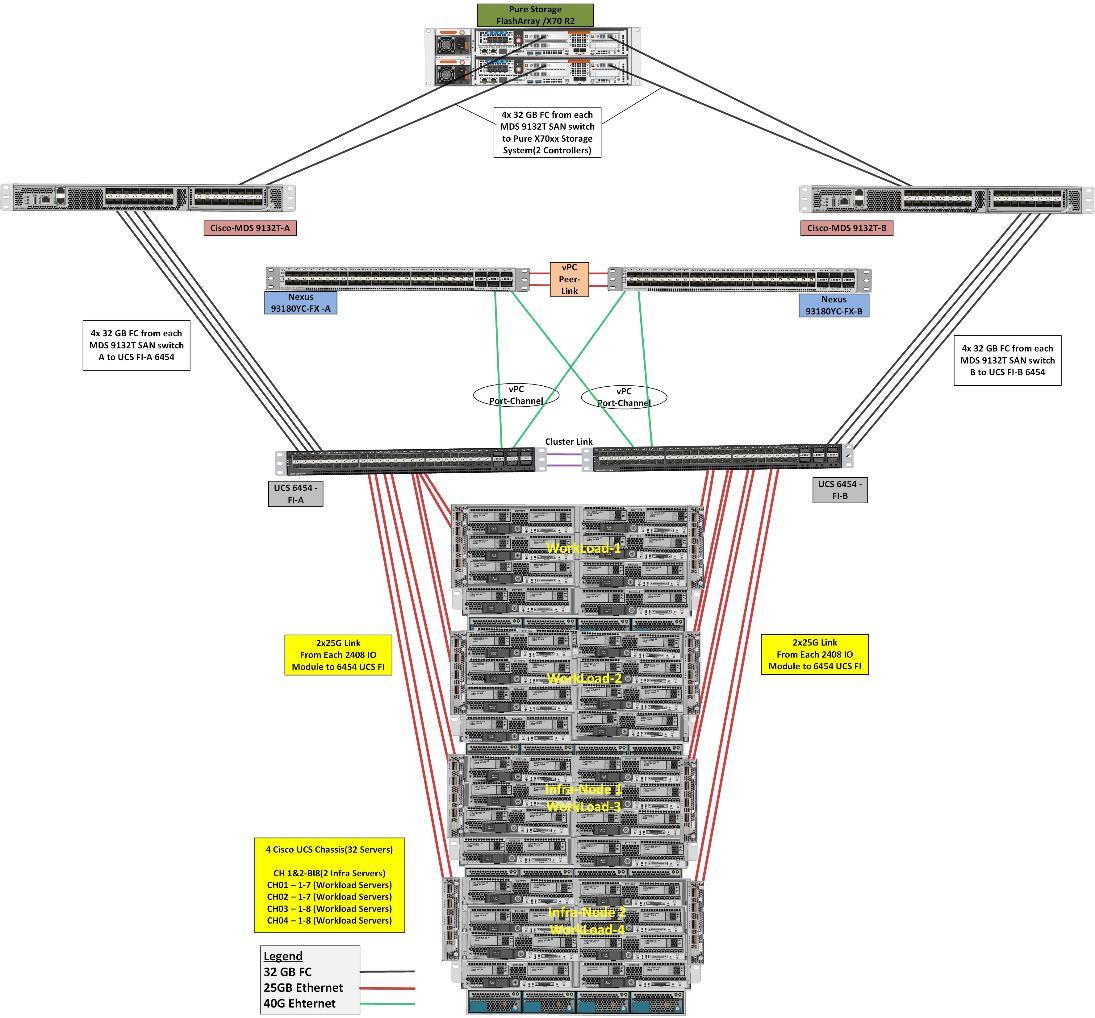
The solution contains the following hardware as shown in Figure 22.
· Two Cisco Nexus 93180YC-FX Layer 2 Access Switches
· Two Cisco MDS 9132T 32-Gb and 16Gb Fibre Channel Switches
· Four Cisco UCS 5108 Blade Server Chassis with two Cisco UCS-IOM-2408 IO Modules
· Two Cisco UCS B200 M5 Blade Servers with Intel® Xeon® Silver 4210 2.2-GHz 10-core processors, 384GB 2933MHz RAM, and one Cisco VIC1340 mezzanine card for the hosted infrastructure, providing N+1 server fault tolerance.
· Thirty Cisco UCS B200 M5 Blade Servers with Intel® Xeon® Gold 6230 2.1-GHz 20-core processors, 768GB 2933MHz RAM, and one Cisco VIC1440 mezzanine card, providing N+1 server fault tolerance.
· Pure Storage FlashArray//X70 R2 with dual redundant controllers, with Twenty 1.92TB DirectFlash NVMe drives
![]() The LoginVSI Test infrastructure is not a part of this solution. The Pure FlashArray//X70 R2 configuration is detailed later in this document.
The LoginVSI Test infrastructure is not a part of this solution. The Pure FlashArray//X70 R2 configuration is detailed later in this document.
Software Revisions
Table 2 lists the software versions of the primary products installed in the environment.
Table 2 Software and Firmware Versions
| Vendor |
Product / Component |
Version / Build / Code |
| Cisco |
UCS Component Firmware |
4.0(4g) bundle release |
| Cisco |
UCS Manager |
4.0(4g) bundle release |
| Cisco |
UCS B200 M5 Blades |
4.0(4g) bundle release |
| Cisco |
VIC 1440 |
4.0(4g) bundle release |
| VMware |
vCenter Server Appliance |
6.7.0.12000 |
| VMware |
vSphere ESXi 6.7 Update 3 |
6.7.0.14320388 |
| Citrix |
XenDesktop VDA |
7.15.4000.653 |
| Citrix |
XenDesktop Controller |
7.15.4000 |
| Citrix |
Provisioning Services |
7.15.15.11 |
| Citrix |
StoreFront Services |
3.12.4000.93 |
| Pure Storage |
FlashArray//X70 R2 |
Purity//FA v5.3.6 |
Logical Architecture
The logical architecture of the validated solution which is designed to support up to 6500 users within a single 42u rack containing 32 blades in 4 chassis, with physical redundancy for the blade servers for each workload type is illustrated in Figure 23.
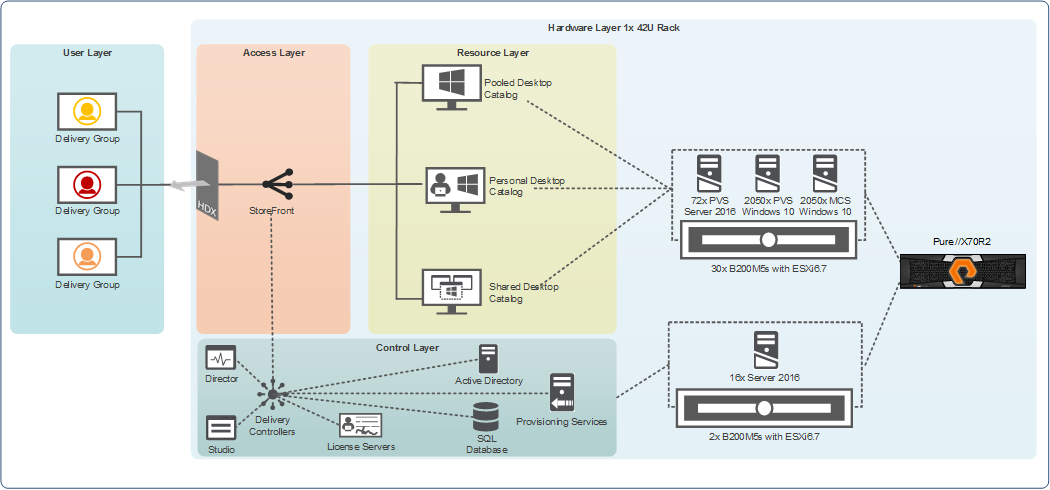
Configuration Guidelines
The Citrix Virtual Apps and Desktops solution described in this document provides details for configuring a fully redundant, highly-available configuration. Configuration guidelines are provided that refer to which redundant component is being configured with each step, whether that be A or B. For example, Nexus A and Nexus B identify the pair of Cisco Nexus switches that are configured. The Cisco UCS Fabric Interconnects are configured similarly.
![]() This document is intended to allow the reader to configure the Citrix Virtual Apps and Desktops 7.15 customer environment as a stand-alone solution.
This document is intended to allow the reader to configure the Citrix Virtual Apps and Desktops 7.15 customer environment as a stand-alone solution.
VLANs
The VLAN configuration recommended for the environment includes a total of six VLANs as outlined in Table 3 .
Table 3 VLANs Configured in this Study
| VLAN Name |
VLAN ID |
VLAN Purpose |
| Default |
1 |
Native VLAN |
| In-Band-Mgmt |
70 |
In-Band management interfaces |
| Infra-Mgmt |
71 |
Infrastructure Virtual Machines |
| VCC/VM-Network |
72 |
HSD, VDI Persistent and Non-Persistent |
| vMotion |
73 |
VMware vMotion |
| OOB-Mgmt |
164 |
Out of Band management interfaces |
VSANs
Two virtual SANs configured for communications and fault tolerance in this design as outlined in Table 4 .
Table 4 VSANs Configured in this Study
| VSAN Name |
VSAN ID |
Purpose |
| VSAN 100 |
100 |
VSAN for Primary SAN communication |
| VSAN 101 |
101 |
VSAN for Secondary SAN communication |
This section details the configuration and tuning that was performed on the individual components to produce a complete, validated solution.
Solution Cabling
The following sections detail the physical connectivity configuration of the FlashStack Citrix Virtual Apps and Desktops environment.
The information provided in this section is a reference for cabling the physical equipment in this Cisco Validated Design environment. To simplify cabling requirements, the tables include both local and remote device and port locations.
The tables in this section contain the details for the prescribed and supported configuration of the Pure Storage FlashArray//X70 R2 storage array to the Cisco 6454 Fabric Interconnects through Cisco MDS 9132T 32-Gb FC switches.
![]() This document assumes that out-of-band management ports are plugged into an existing management infrastructure at the deployment site. These interfaces will be used in various configuration steps.
This document assumes that out-of-band management ports are plugged into an existing management infrastructure at the deployment site. These interfaces will be used in various configuration steps.
![]() Be sure to follow the cabling directions in this section. Failure to do so will result in necessary changes to the deployment procedures that follow because specific port locations are mentioned.
Be sure to follow the cabling directions in this section. Failure to do so will result in necessary changes to the deployment procedures that follow because specific port locations are mentioned.
Figure 24 shows a cabling diagram for a configuration using the Cisco Nexus 9000, Cisco MDS 9100 Series, and Pure Storage FlashArray//X70 R2 array.
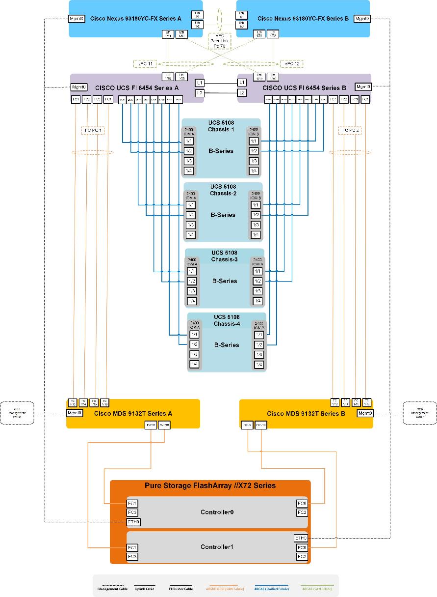
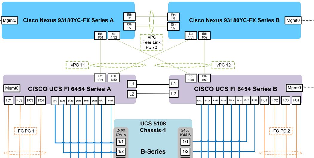
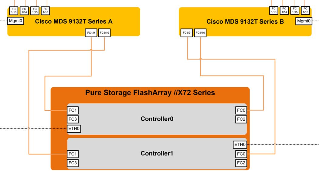
Cisco Unified Computing System Base Configuration
This section details the Cisco UCS configuration that was done as part of the infrastructure build-out. The racking, power, and installation of the chassis are beyond the scope of this document, however they are described in the Cisco UCS Manager Getting Started Guide. For more information about each step, refer to the Cisco UCS Manager - Configuration Guides.
Cisco UCS Manager Software Version 4.0(4g)
This document assumes you are using Cisco UCS Manager Software version 4.0(4g). To upgrade the Cisco UCS Manager software and the Cisco UCS 6454 Fabric Interconnect software to a higher version of the firmware,) refer to Cisco UCS Manager Install and Upgrade Guides.
Configure Fabric Interconnects at Console
To configure the fabric Interconnects, follow these steps:
1. Connect a console cable to the console port on what will become the primary fabric interconnect.
2. If the fabric interconnect was previously deployed and you want to erase it to redeploy, follow these steps:
a. Login with the existing user name and password.
# connect local-mgmt
# erase config
# yes (to confirm)
3. After the fabric interconnect restarts, the out-of-box first time installation prompt appears, type “console” and press Enter.
4. Follow the Initial Configuration steps as outlined in Cisco UCS Manager Getting Started Guide. When configured, Login to UCSM IP Address through Web interface to perform base Cisco UCS configuration.
Configure Fabric Interconnects for a Cluster Setup
To configure the Cisco UCS Fabric Interconnects, follow these steps:
1. Verify the following physical connections on the fabric interconnect:
- The management Ethernet port (mgmt0) is connected to an external hub, switch, or router
- The L1 ports on both fabric interconnects are directly connected to each other
- The L2 ports on both fabric interconnects are directly connected to each other
2. Connect to the console port on the first Fabric Interconnect.
3. Review the settings on the console. Answer yes to Apply and Save the configuration.
4. Wait for the login prompt to make sure the configuration has been saved to Fabric Interconnect A.
5. Connect the console port on the second Fabric Interconnect, configure secondary FI.
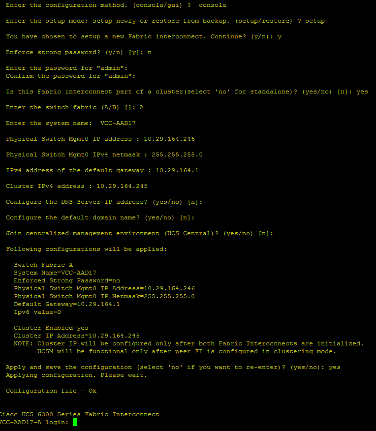
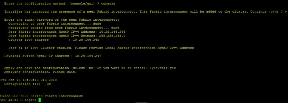
6. To log into the Cisco Unified Computing System (Cisco UCS) environment, follow these steps:
a. Open a web browser and navigate to the Cisco UCS Fabric Interconnect cluster address configured above.
b. Click the Launch UCS Manager link to download the Cisco UCS Manager software. If prompted, accept the security certificates.
7. When prompted, enter the user name and password enter the password. Click Log In to log into Cisco UCS Manager.
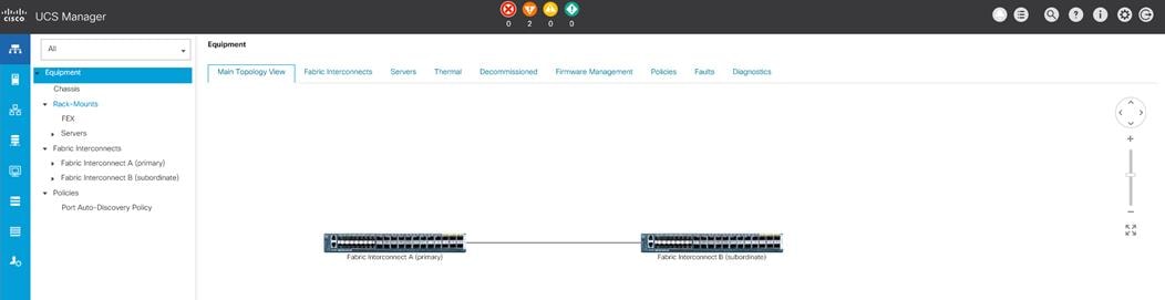
Configure Base Cisco Unified Computing System
The following are the high-level steps involved for a Cisco UCS configuration:
· Configure Fabric Interconnects for a Cluster Setup
· Set Fabric Interconnects to Fibre Channel End Host Mode
· Synchronize Cisco UCS to NTP
· Configure Fabric Interconnects for Chassis and Blade Discovery
- Configure Global Policies
- Configure Server Ports
· Configure LAN and SAN on Cisco UCS Manager
- Configure Ethernet LAN Uplink Ports
- Create Uplink Port Channels to Cisco Nexus Switches
- Configure FC SAN Uplink Ports
- Configure VLAN
- Configure VSAN
· Configure IP, UUID, Server, MAC, WWNN and WWPN Pools
- IP Pool Creation
- UUID Suffix Pool Creation
- Server Pool Creation
- MAC Pool Creation
· WWNN and WWPN Pool Creation
· Set Jumbo Frames in both the Cisco Fabric Interconnect
· Configure Server BIOS Policy
· Create Adapter Policy
· Configure Update Default Maintenance Policy
· Configure vNIC and vHBA Template
· Create Server Boot Policy for SAN Boot
Details for each step are discussed in the following sections.
Synchronize Cisco UCSM to NTP
To synchronize the Cisco UCS environment to the NTP server, follow these steps:
1. In Cisco UCS Manager, in the navigation pane, click the Admin tab.
2. Select All > Time zone Management.
3. In the Properties pane, select the appropriate time zone in the Time zone menu.
4. Click Save Changes and then click OK.
5. Click Add NTP Server.
6. Enter the NTP server IP address and click OK.
7. Click OK to finish.
8. Click Save Changes.
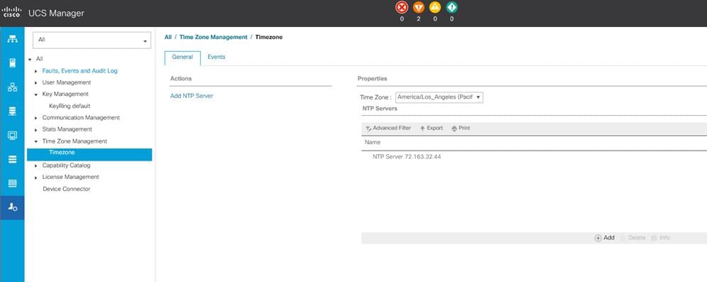
9. Configure Fabric Interconnects for Chassis and Blade Discovery
Cisco UCS 6454 Fabric Interconnects are configured for redundancy. It provides resiliency in case of failures. The first step is to establish connectivity between blades and Fabric Interconnects.
Configure Global Policies
The chassis discovery policy determines how the system reacts when you add a new chassis. We recommend using the platform max value as shown. Using platform max helps ensure that Cisco UCS Manager uses the maximum number of IOM uplinks available.
To configure global policies, follow these steps:
1. In Cisco UCS Manager, go to Equipment > Policies (right pane) > Global Policies > Chassis/FEX Discovery Policies. From the Action drop-down list, select Platform Max and set Link Grouping to Port Channel.
2. Click Save Changes.
3. Click OK.
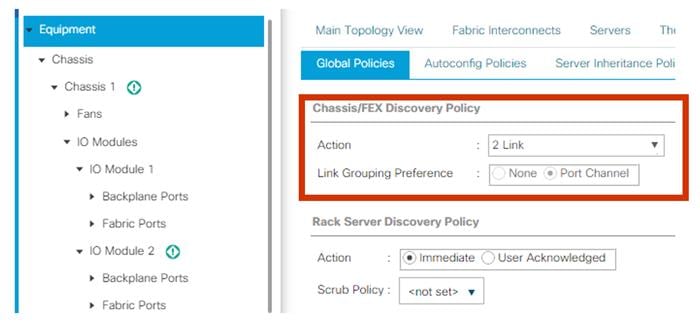
Fabric Ports: Discrete versus Port Channel Mode
Figure 33 illustrates the advantage of Discrete Vs Port-Channel mode in UCSM.
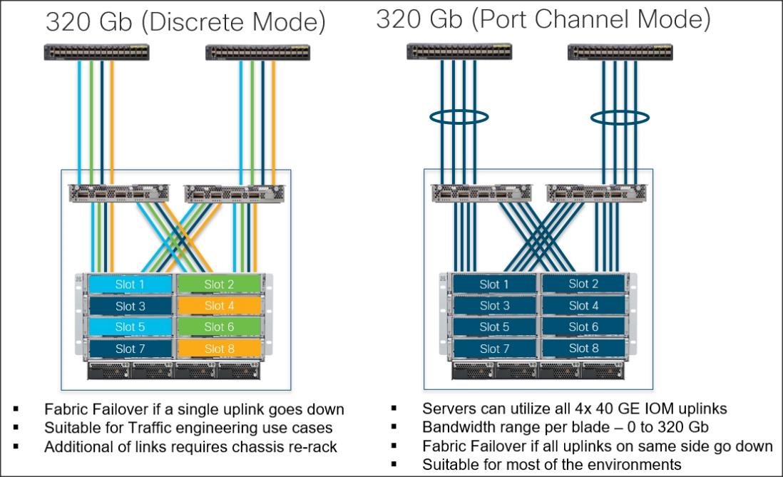
Set Fabric Interconnects to Fibre Channel End Host Mode
In order to configure FC Uplink ports connected to Cisco UCS MDS 9132T 32-Gb FC switch set the Fabric Interconnects to the Fibre Channel End Host Mode. Verify that Fabric Interconnects are operating in “FC End-Host Mode.”
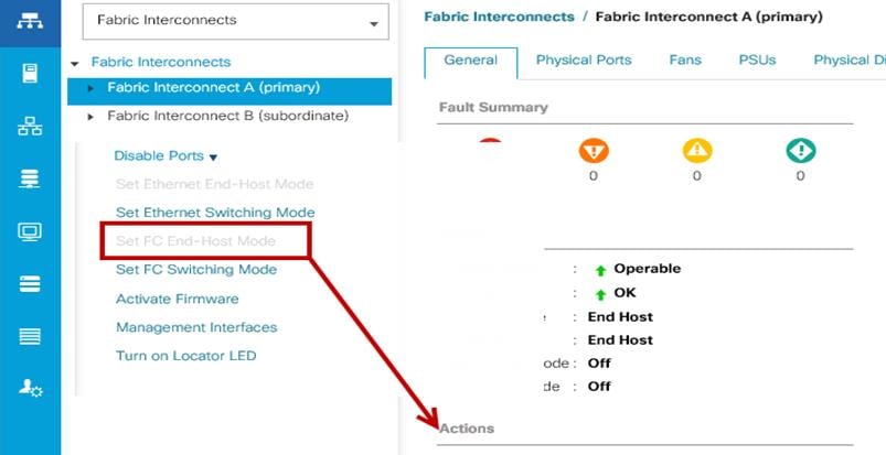
![]() Fabric Interconnect automatically reboot if switched operational mode; perform this task on one FI first, wait for FI to come up and follow the same on second FI.
Fabric Interconnect automatically reboot if switched operational mode; perform this task on one FI first, wait for FI to come up and follow the same on second FI.
Configure FC SAN Uplink Ports
To configure Fibre Channel Uplink ports, follow these steps:
1. Go to Equipment > Fabric Interconnects > Fabric Interconnect A > General tab > Actions pane, click Configure Unified ports.
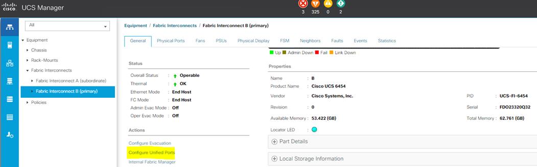
2. Click Yes to confirm in the pop-up window.
3. Move the slider to the right.
4. Click OK.
![]() Ports to the right of the slider will become FC ports. For our study, we configured the first six ports on the FI as FC Uplink ports.
Ports to the right of the slider will become FC ports. For our study, we configured the first six ports on the FI as FC Uplink ports.
![]() Applying this configuration will cause the immediate reboot of Fabric Interconnect and/or Expansion Module(s).
Applying this configuration will cause the immediate reboot of Fabric Interconnect and/or Expansion Module(s).
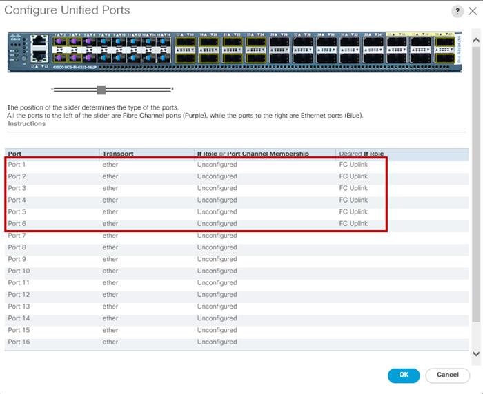
5. Click Yes to apply the changes.
6. Repeat steps 1-5 for Fabric Interconnect B.
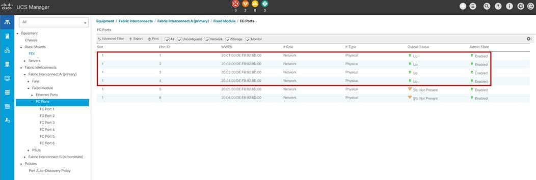
Configure Server Ports
Configure the server ports to initiate chassis and blade discovery. To configure server ports, follow these steps:
1. Go to Equipment > Fabric Interconnects > Fabric Interconnect A > Fixed Module > Ethernet Ports.
2. Select the ports (for this solution ports are 17-24) which are connected to the Cisco IO Modules of the two B-Series 5108 Chassis.
3. Right-click and select Configure as Server Port.
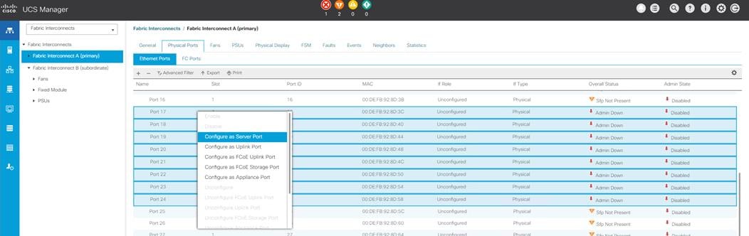
4. Click Yes to confirm and click OK.
5. Repeat steps 1-4 to configure the Server Port on Fabric Interconnect B.
When configured, the server port will look like the screenshot shown below on both Fabric Interconnects.
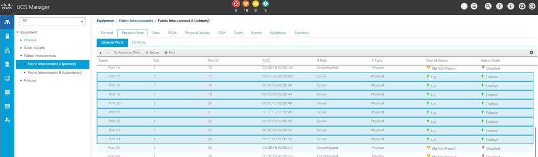
6. After configuring Server Ports, acknowledge both the Chassis. Go to Equipment >Chassis > Chassis 1 > General > Actions > select “Acknowledge Chassis”. Similarly, acknowledge the chassis 2-4.
7. After acknowledging both the chassis, re-acknowledge all the servers placed in the chassis. Go to Equipment > Chassis 1 > Servers > Server 1 > General > Actions > select Server Maintenance > select option “Re-acknowledge” and click OK. Repeat this process to re-acknowledge all eight Servers.
8. When the acknowledgement of the Servers is completed, verify the Port-channel of Internal LAN. Go to the LAN tab > Internal LAN > Internal Fabric A > Port Channels as shown below.
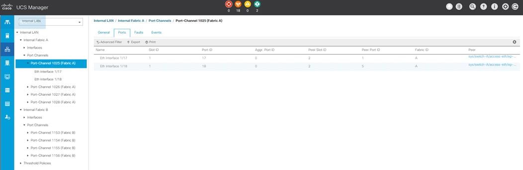
Configure Ethernet LAN Uplink Ports
To configure network ports that are used to uplink the Fabric Interconnects to the Cisco Nexus switches, follow these steps:
1. In Cisco UCS Manager, in the navigation pane, click the Equipment tab.
2. Select Equipment > Fabric Interconnects > Fabric Interconnect A > Fixed Module.
3. Expand Ethernet Ports.
4. Select ports (for this solution ports are 49-50) that are connected to the Nexus switches, right-click them, and select Configure as Network Port.
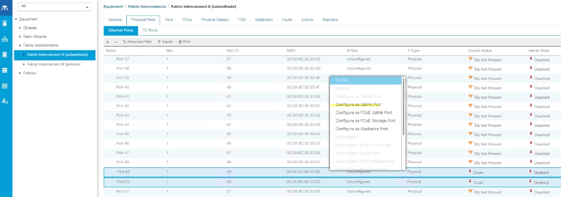
5. Click Yes to confirm ports and click OK.
6. Verify the Ports connected to Cisco Nexus upstream switches are now configured as network ports.
7. Repeat steps 1-6 for Fabric Interconnect B. The screenshot below shows the network uplink ports for Fabric A.
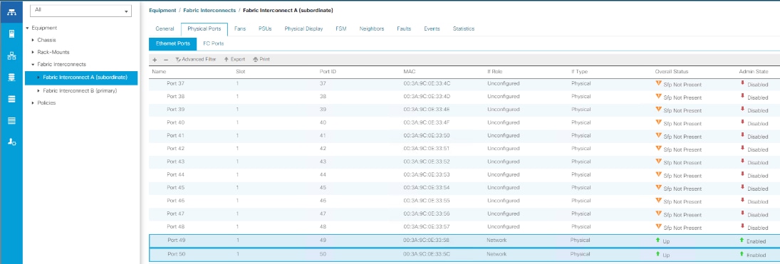
You have now created two uplink ports on each Fabric Interconnect as shown above. These ports will be used to create Virtual Port Channel in the next section.
Create Uplink Port Channels to Cisco Nexus Switches
In this procedure, two port channels were created; one from Fabric A to both Cisco Nexus 93180YC-FX switches and one from Fabric B to both Cisco Nexus 93180YC-FX switches. To configure the necessary port channels in the Cisco UCS environment, follow these steps:
1. In Cisco UCS Manager, click the LAN tab in the navigation pane.
2. Under LAN > LAN Cloud, expand node Fabric A tree:
a. Right-click Port Channels.
b. Select Create Port Channel.
c. Enter 11 as the unique ID of the port channel.
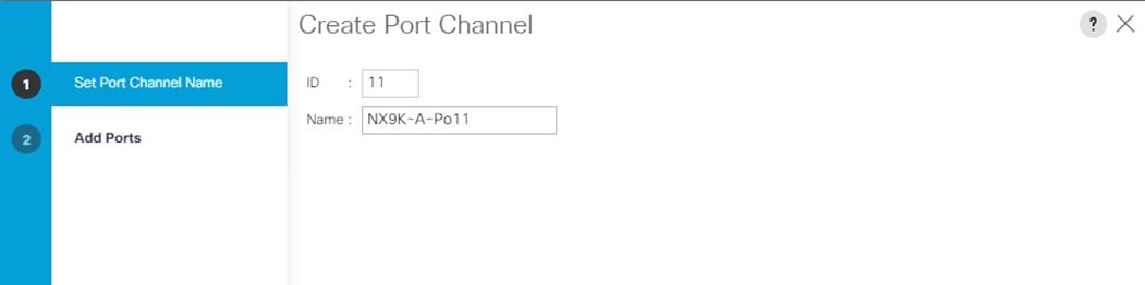
3. Enter name of the port channel.
4. Click Next.
5. Select Ethernet ports 49-50 for the port channel.
6. Click Finish.
7. Repeat steps 1-6 for the Port Channel configuration on FI-B.
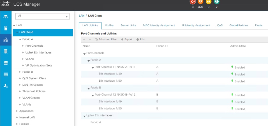
Configure VLAN
To configure the necessary virtual local area networks (VLANs) for the Cisco UCS environment, follow these steps:
1. In Cisco UCS Manager, click the LAN tab in the navigation pane.
2. Select LAN > LAN Cloud.
3. Right-click VLANs.
4. Select Create VLANs.
5. Enter Public_Traffic as the name of the VLAN to be used for Public Network Traffic.
6. Keep the Common/Global option selected for the scope of the VLAN.
7. Enter 134 as the ID of the VLAN ID.
8. Keep the Sharing Type as None.
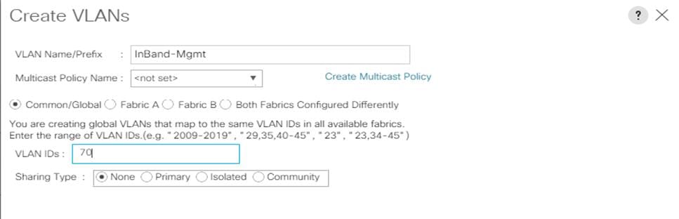
9. Repeat steps 1-8 to create required VLANs. Figure 40 shows the VLANs configured for this solution.
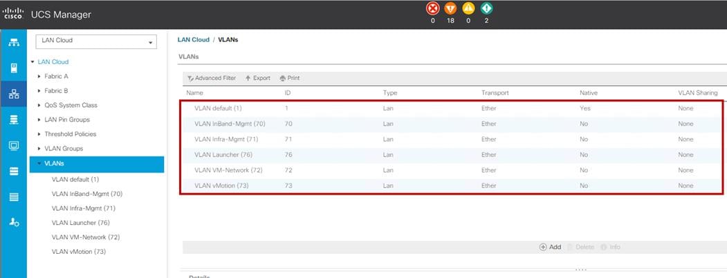
![]() IMPORTANT! Create both VLANs with global across both fabric interconnects. This makes sure the VLAN identity is maintained across the fabric interconnects in case of a NIC failover.
IMPORTANT! Create both VLANs with global across both fabric interconnects. This makes sure the VLAN identity is maintained across the fabric interconnects in case of a NIC failover.
Configure VSAN
To configure the necessary virtual storage area networks (VSANs) for the Cisco UCS environment, follow these steps:
1. In Cisco UCS Manager, click the SAN tab in the navigation pane.
2. Select SAN > SAN Cloud.
3. Under VSANs, right-click VSANs.
4. Select Create VSANs.
5. Enter the name of the VSAN.
6. Enter VSAN ID and FCoE VLAN ID.
7. Click OK.
![]() In this solution, we created two VSANs; VSAN-A 100 and VSAN-B 101 for SAN Boot and Storage Access.
In this solution, we created two VSANs; VSAN-A 100 and VSAN-B 101 for SAN Boot and Storage Access.
8. Select Fabric A for the scope of the VSAN:
a. Enter 100 as the ID of the VSAN.
b. Click OK and then click OK again.
9. Repeat steps 1-8 to create the VSANs necessary for this solution.
VSAN 100 and 101 are configured as shown below:
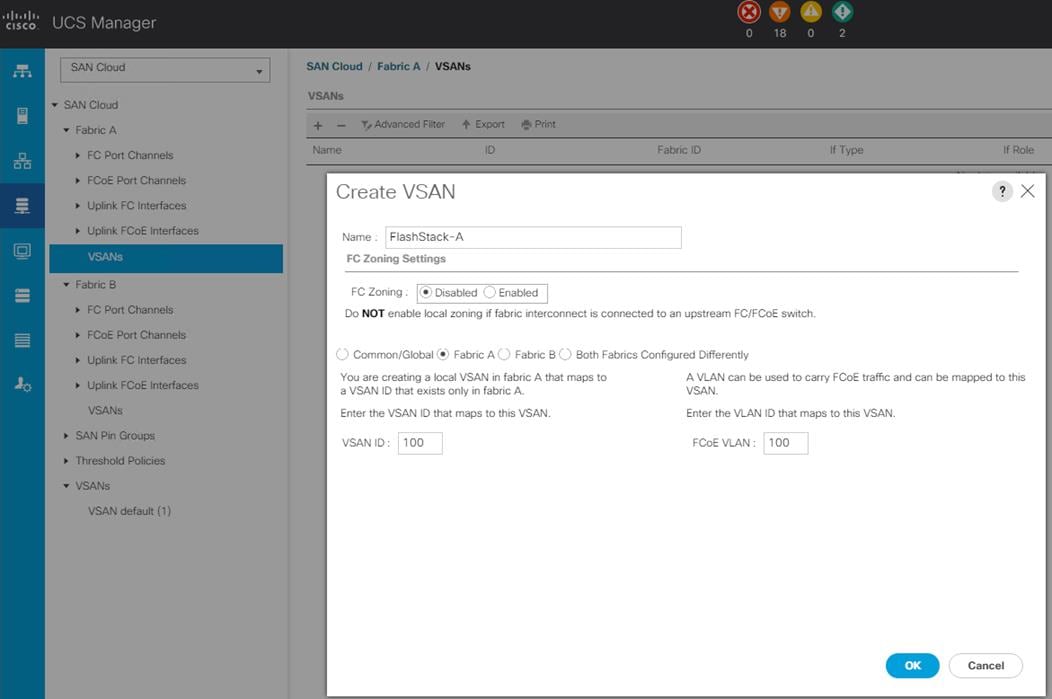
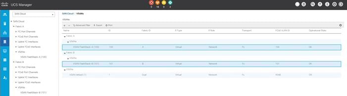
Create New Sub-Organization
To configure the necessary Sub-Organization for the Cisco UCS environment, follow these steps:
1. In Cisco UCS Manager, click the Servers tab in the navigation pane.
2. Select root > Sub-Organization.
3. Right-click Sub-Organization.
4. Enter the name of the Sub-Organization.
5. Click OK.
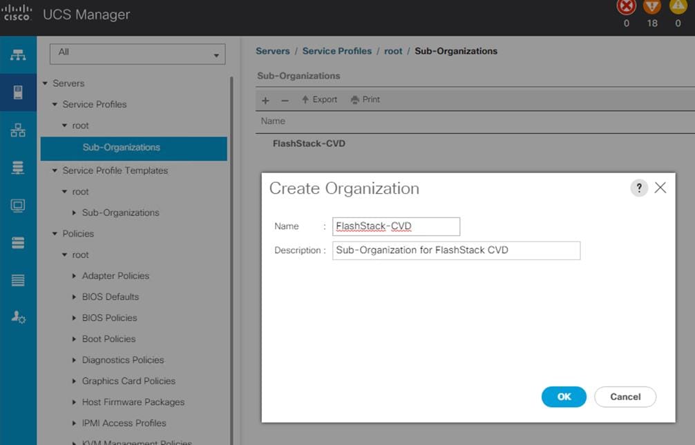
![]() You will create pools and policies required for this solution under the newly created “FlashStack-CVD” sub-organization.
You will create pools and policies required for this solution under the newly created “FlashStack-CVD” sub-organization.
Configure IP, UUID, Server, MAC, WWNN, and WWPN Pools
IP Pool Creation
An IP address pool on the out of band management network must be created to facilitate KVM access to each compute node in the Cisco UCS domain. To create a block of IP addresses for server KVM access in the Cisco UCS environment, follow these steps:
1. In Cisco UCS Manager, in the navigation pane, click the LAN tab.
2. Select Pools > root > Sub-Organizations > FlashStack-CVD > IP Pools > click Create IP Pool.
3. Select option Sequential to assign IP in sequential order then click Next.
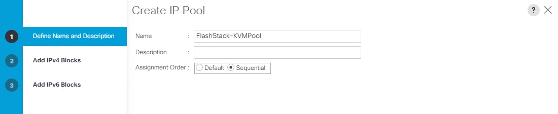
4. Click Add IPv4 Block.
5. Enter the starting IP address of the block and the number of IP addresses required, and the subnet and gateway information as shown below.
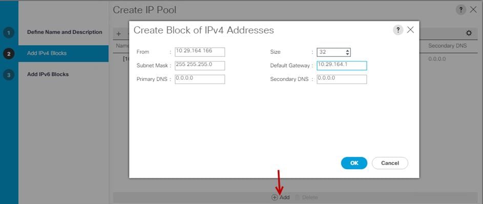
UUID Suffix Pool Creation
To configure the necessary universally unique identifier (UUID) suffix pool for the Cisco UCS environment, follow these steps:
1. In Cisco UCS Manager, click the Servers tab in the navigation pane.
2. Select Pools > root > Sub-Organization > FlashStack-CVD
3. Right-click UUID Suffix Pools and then select Create UUID Suffix Pool.
4. Enter the name of the UUID name.
5. Optional: Enter a description for the UUID pool.
6. Keep the prefix at the derived option and select Sequential in as Assignment Order then click Next.
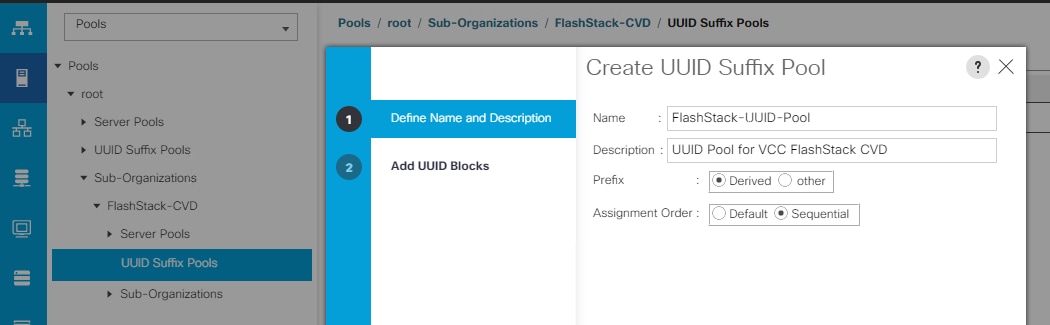
7. Click Add to add a block of UUIDs.
8. Create a starting point UUID as per your environment.
9. Specify a size for the UUID block that is sufficient to support the available blade or server resources.

Server Pool Creation
To configure the necessary server pool for the Cisco UCS environment, follow these steps:
![]() Consider creating unique server pools to achieve the granularity that is required in your environment.
Consider creating unique server pools to achieve the granularity that is required in your environment.
1. In Cisco UCS Manager, click the Servers tab in the navigation pane.
2. Select Pools > root > Sub-Organization > FlashStack-CVD > right-click Server Pools > Select Create Server Pool.
3. Enter name of the server pool.
4. Optional: Enter a description for the server pool then click Next.
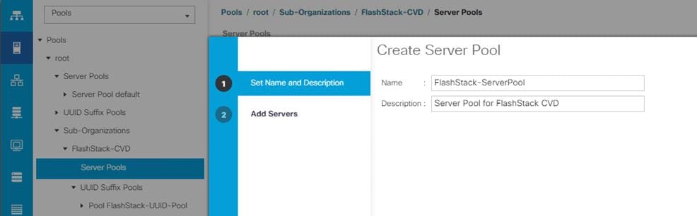
5. Select servers to be used for the deployment and click > to add them to the server pool. In our case we added thirty servers in this server pool.
6. Click Finish and then click OK.
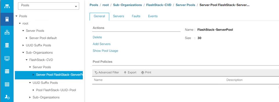
MAC Pool Creation
To configure the necessary MAC address pools for the Cisco UCS environment, follow these steps:
1. In Cisco UCS Manager, click the LAN tab in the navigation pane.
2. Select Pools > root > Sub-Organization > FlashStack > right-click MAC Pools under the root organization.
3. Select Create MAC Pool to create the MAC address pool.
4. Enter name for MAC pool. Select Sequential for the Assignment Order.
5. Enter the seed MAC address and provide the number of MAC addresses to be provisioned.
6. Click OK and then click Finish.
7. In the confirmation message, click OK.
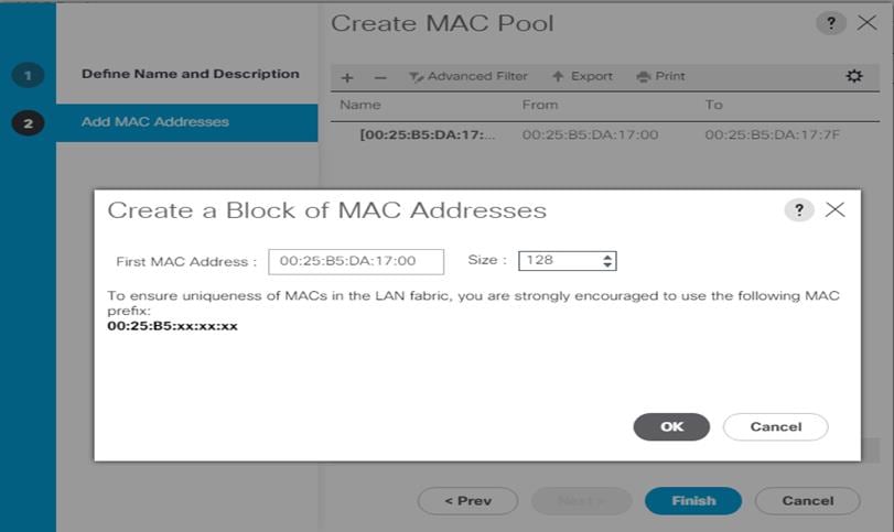
8. Create MAC Pool B and assign unique MAC Addresses as shown below.
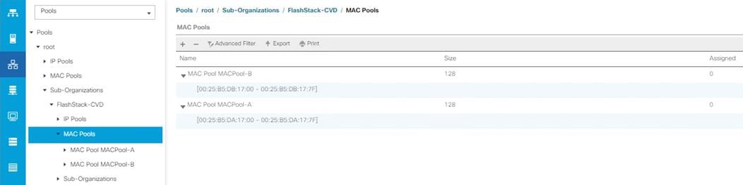
WWNN and WWPN Pool Creation
To configure the necessary WWNN pools for the Cisco UCS environment, follow these steps:
1. In Cisco UCS Manager, click the SAN tab in the navigation pane.
2. Select Pools > Root > Sub-Organization > FlashStack-CVD > WWNN Pools > right-click WWNN Pools > select Create WWNN Pool.
3. Assign name and select Sequential for the Assignment Order.
4. Click Next and then click Add to add block of Ports.
5. Enter Block for WWN and size of WWNN Pool as shown below.
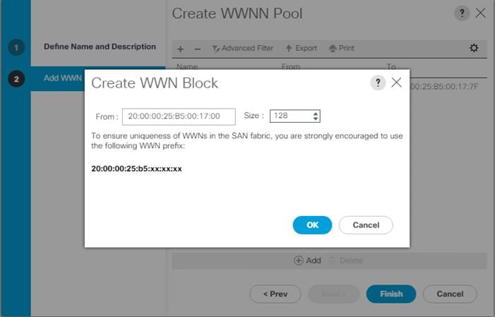
6. Click OK and then click Finish.
To configure the necessary WWPN pools for the Cisco UCS environment, follow these steps:
![]() We created two WWPN as WWPN-A Pool and WWPN-B as Worldwide Port Name as shown below. These WWNN and WWPN entries will be used to access storage through SAN configuration.
We created two WWPN as WWPN-A Pool and WWPN-B as Worldwide Port Name as shown below. These WWNN and WWPN entries will be used to access storage through SAN configuration.
1. In Cisco UCS Manager, click the SAN tab in the navigation pane.
2. Select Pools > Root > WWPN Pools > right-click WWPN Pools > select Create WWPN Pool.
3. Assign name and Assignment Order as sequential.
4. Click Next and then click Add to add block of Ports.
5. Enter Block for WWN and size.
6. Click OK and then click Finish.
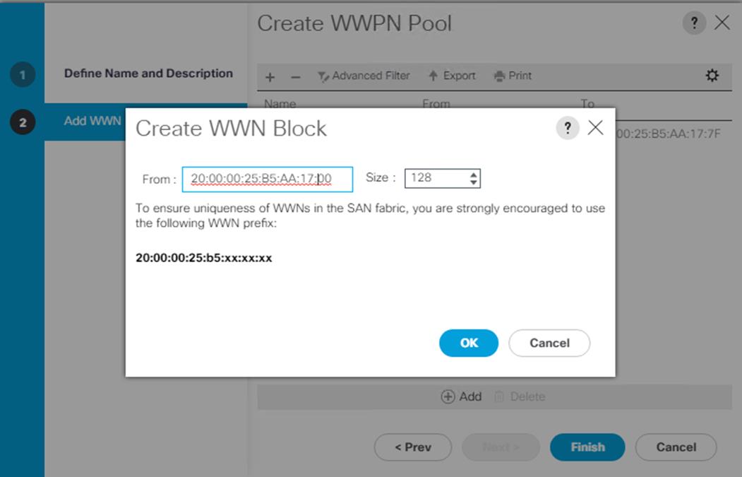
7. Configure WWPN-Bs Pool as well and assign the unique block IDs as shown below.
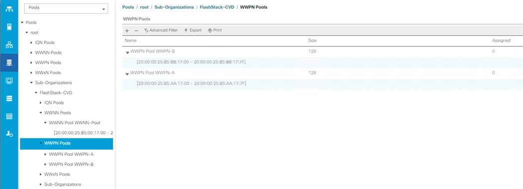
Set Jumbo Frames in both the Cisco Fabric Interconnect
To configure jumbo frames and enable quality of service in the Cisco UCS fabric, follow these steps:
1. In Cisco UCS Manager, click the LAN tab in the navigation pane.
2. Select LAN > LAN Cloud > QoS System Class.
3. In the right pane, click the General tab.
4. On the Best Effort row, enter 9216 in the box under the MTU column.
5. Click Save Changes.
6. Click OK.
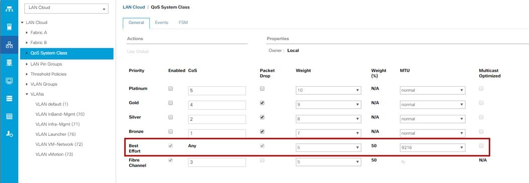
Create Host Firmware Package
Firmware management policies allow the administrator to select the corresponding packages for a given server configuration. These policies often include packages for adapter, BIOS, board controller, FC adapters, host bus adapter (HBA) option ROM, and storage controller properties.
To create a firmware management policy for a given server configuration in the Cisco UCS environment, follow these steps:
1. In Cisco UCS Manager, click the Servers tab in the navigation pane.
2. Select root > Sub-Organization > FlashStack-CVD > Host Firmware Packages.
3. Right-click Host Firmware Packages.
4. Select Create Host Firmware Package.
5. Enter name of the host firmware package.
6. Leave Simple selected.
7. Select the version 4.0(4g) for both the Blade Package.
8. Click OK to create the host firmware package.
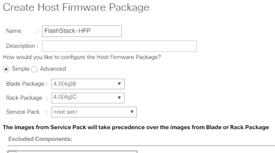
Create Server Pool Policy
Create Server Pools Policy
Creating the server pool policy requires you to create the Server Pool Policy and Server Pool Qualification Policy.
To create a Server Pools Policy, follow these steps:
1. In Cisco UCS Manager, click the Servers tab in the navigation pane.
2. Select Pools > root > Sub-Organization > FlashStack-CVD > Server Pools.
3. Right-click Server Pools Select Create Server Pools Policy; Enter Policy name.
4. Select server from left pane to add as pooled server.
![]() In our case, we created two server pools policies. For the “VDI-CVD01” policy, we added Servers as Chassis 1 Slot 1-8 and Chassis 3 Slot 1-8 and for the “VDI-CVD02” policy, we added Chassis 2 Slot 1-8 and Chassis 4 Slot 1-8.
In our case, we created two server pools policies. For the “VDI-CVD01” policy, we added Servers as Chassis 1 Slot 1-8 and Chassis 3 Slot 1-8 and for the “VDI-CVD02” policy, we added Chassis 2 Slot 1-8 and Chassis 4 Slot 1-8.
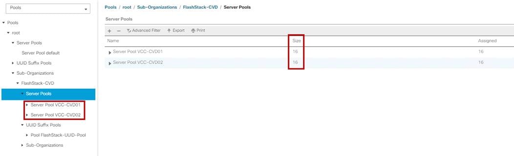
Create Server Pool Policy Qualifications
To create a Server Pool Policy Qualification Policy complete following steps:
1. In Cisco UCS Manager, click the Servers tab in the navigation pane.
2. Select Pools > root > Sub-Organization > FlashStack-CVD > Server Pool Policy Qualification.
3. Right-click Server Pools Select Create Server Pool Policy Qualification; Enter Policy name.
4. Select Chassis/Server Qualification from left pane to add in Qualifications.
5. Click Add or OK to either Add more servers to existing policy to Finish creation of Policy.
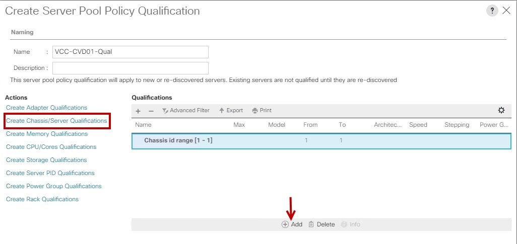
![]() In our case, we created two server pools policies. For the “VDI-CVD01” policy, we added Servers as Chassis 1 Slot 1-8 and Chassis 3 Slot 1-8 and for the “VDI-CVD02” policy, we added Chassis 2 Slot 1-8 and Chassis 4 Slot 1-8.
In our case, we created two server pools policies. For the “VDI-CVD01” policy, we added Servers as Chassis 1 Slot 1-8 and Chassis 3 Slot 1-8 and for the “VDI-CVD02” policy, we added Chassis 2 Slot 1-8 and Chassis 4 Slot 1-8.
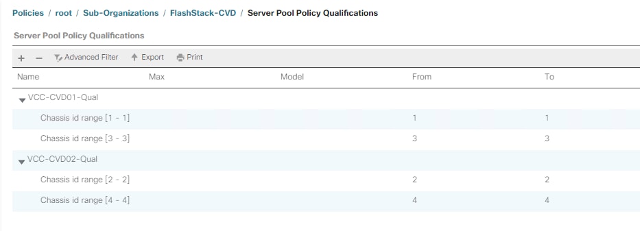
To create a Server Pool Policy, follow these steps:
1. In Cisco UCS Manager, click the Servers tab in the navigation pane.
2. Select Pools > root > Sub-Organization > FlashStack-CVD > Server Pool Policies.
3. Right-click Server Pool Policies and Select Create Server Pool Policy; Enter Policy name.
4. Select Target Pool and Qualification from the drop-down list.
5. Click OK.
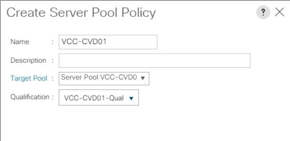
![]() We created two Server Pool Policies to associate with the Service Profile Templates “VDI-CVD01” and “VDI-CVD02” as described in this section.
We created two Server Pool Policies to associate with the Service Profile Templates “VDI-CVD01” and “VDI-CVD02” as described in this section.
Create Network Control Policy for Cisco Discovery Protocol
To create a network control policy that enables Cisco Discovery Protocol (CDP) on virtual network ports, follow these steps:
1. In Cisco UCS Manager, click the LAN tab in the navigation pane.
2. Select Policies > root > Sub-Organization > FlashStack-CVD > Network Control Policies.
3. Right-click Network Control Policies.
4. Select Create Network Control Policy.
5. Enter policy name.
6. Select the Enabled option for “CDP.”
7. Click OK to create the network control policy.
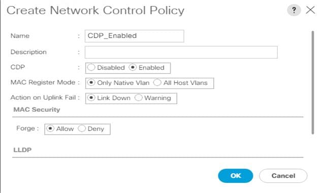
Create Power Control Policy
To create a power control policy for the Cisco UCS environment, follow these steps:
1. In Cisco UCS Manager, click the Servers tab in the navigation pane.
2. Select Policies > root > Sub-Organization > FlashStack-CVD > Power Control Policies.
3. Right-click Power Control Policies.
4. Select Create Power Control Policy.
5. Select Max Power for the Fan Speed Policy.
6. Enter NoPowerCap as the power control policy name.
7. Change the power capping setting to No Cap.
8. Click OK to create the power control policy.
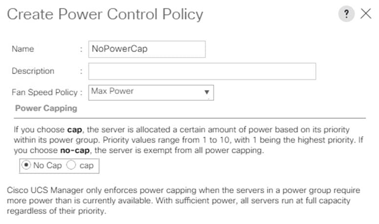
Create Server BIOS Policy
To create a server BIOS policy for the Cisco UCS environment, follow these steps:
1. In Cisco UCS Manager, click the Servers tab in the navigation pane.
2. Select Policies > root > Sub-Organization > FlashStack-CVD > BIOS Policies.
3. Right-click BIOS Policies.
4. Select Create BIOS Policy.
5. Enter B200-M5-BIOS as the BIOS policy name.
6. Leave all BIOS settings as Platform Default.
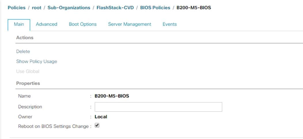
Configure Maintenance Policy
To update the default Maintenance Policy, follow these steps:
1. In Cisco UCS Manager, click the Servers tab in the navigation pane.
2. Select Policies > root > Sub-Organization > FlashStack-CVD > Maintenance Policies.
3. Right-click Maintenance Policies to create a new policy.
4. Enter name for Maintenance Policy
5. Change the Reboot Policy to User Ack.
6. Click Save Changes.
7. Click OK to accept the change.
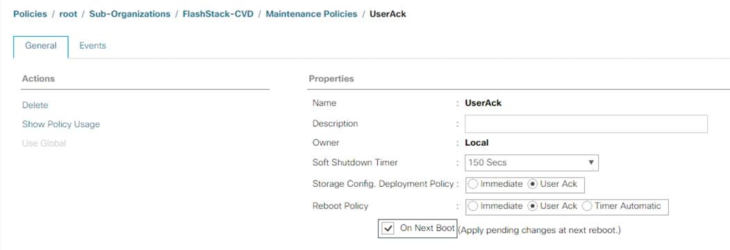
Create vNIC Templates
To create multiple virtual network interface card (vNIC) templates for the Cisco UCS environment, follow these steps:
1. In Cisco UCS Manager, click the LAN tab in the navigation pane.
2. Select Policies > root > Sub-Organization > FlashStack-CVD > vNIC Template.
3. Right-click vNIC Templates.
4. Select Create vNIC Template.
5. Enter name for vNIC template.
6. Keep Fabric A selected. Do not select the Enable Failover checkbox.
7. For Redundancy Type, select Primary Template.
8. Select Updating Template for the Template Type.
9. Under VLANs, select the checkboxes for desired VLANs to add as part of the vNIC Template.
10. Set Native-VLAN as the native VLAN.
11. For MTU, enter 9000.
12. In the MAC Pool list, select MAC Pool configure for Fabric A.
13. In the Network Control Policy list, select CDP_Enabled.
14. Click OK to create the vNIC template.
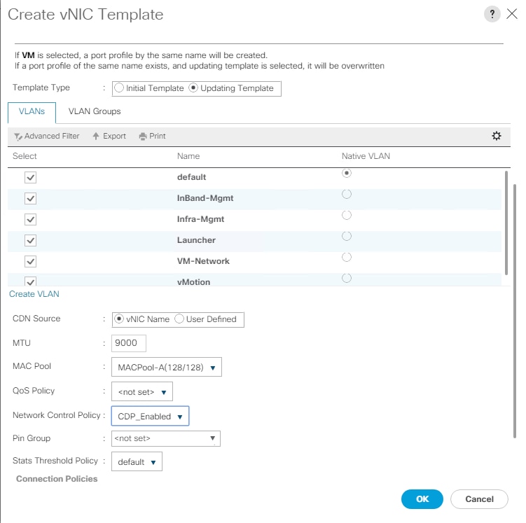
15. Repeat steps 1-14 to create a vNIC Template for Fabric B. For Peer redundancy Template Select “vNIC-Template-A” created in the previous step.
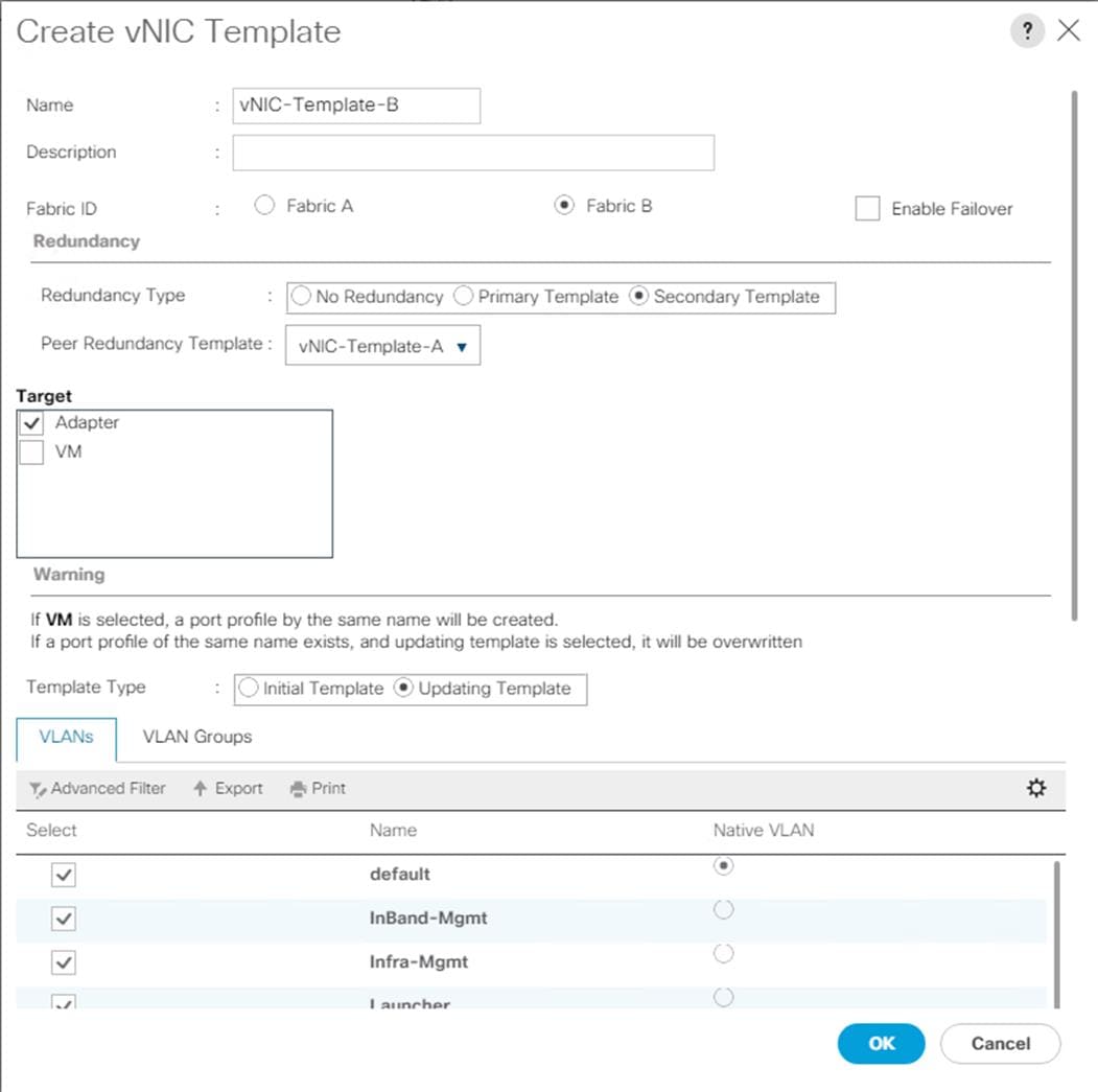
16. Verify that vNIC-Template-A Peer Redundancy Template is set to “vNIC-Template-B.”
Create vHBA Templates
To create multiple virtual host bus adapter (vHBA) templates for the Cisco UCS environment, follow these steps:
1. In Cisco UCS Manager, click the SAN tab in the navigation pane.
2. Select Policies > root > Sub-Organization > FlashStack-CVD > vHBA Template.
3. Right-click vHBA Templates.
4. Select Create vHBA Template.
5. Enter vHBA-A as the vHBA template name.
6. Keep Fabric A selected.
7. Select VSAN created for Fabric A from the drop-down list.
8. Change to Updating Template.
9. For Max Data Field keep 2048.
10. Select WWPN Pool for Fabric A (created earlier) for our WWPN Pool.
11. Leave the remaining fields as is.
12. Click OK.
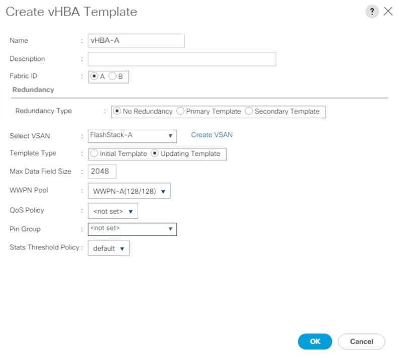
13. Repeat steps 1-12 to create a vHBA Template for Fabric B.
Create Server Boot Policy for SAN Boot
All Cisco UCS B200 M5 Blade Servers for workload and the two Infrastructure servers were set to boot from SAN for this Cisco Validated Design as part of the Service Profile template. The benefits of booting from SAN are numerous; disaster recovery, lower cooling, and power requirements for each server since a local drive is not required, and better performance, to name just a few.
![]() We strongly recommend using “Boot from SAN” to realize the full benefits of Cisco UCS stateless computing features, such as service profile mobility.
We strongly recommend using “Boot from SAN” to realize the full benefits of Cisco UCS stateless computing features, such as service profile mobility.
This process applies to a Cisco UCS environment in which the storage SAN ports are configured as explained in the following section.
![]() A Local disk configuration for the Cisco UCS is necessary if the servers in the environments have a local disk.
A Local disk configuration for the Cisco UCS is necessary if the servers in the environments have a local disk.
To configure Local disk policy, follow these steps:
1. Go to tab Servers > Policies > root > Sub-Organization > FlashStack-CVD > right-click Local Disk Configuration Policy > Enter “SAN-Boot” as the local disk configuration policy name and change the mode to “No Local Storage.”
2. Click OK to create the policy.
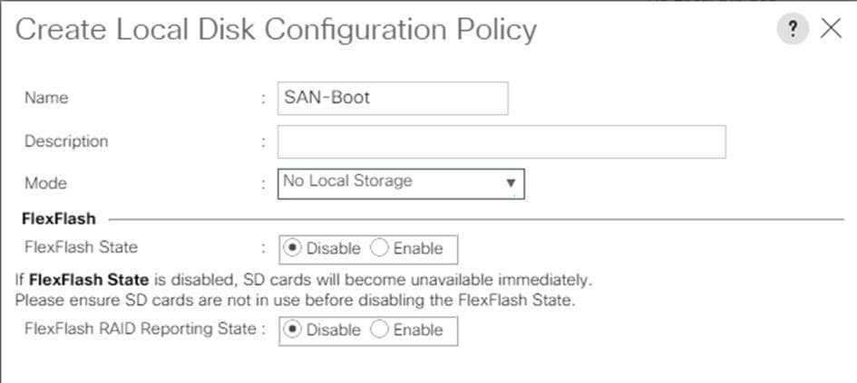
As shown in the screenshot below, the Pure Storage FlashArray have eight active FC connections that pair with the Cisco MDS 9132T 32-Gb switches. Two FC ports are connected to Cisco MDS-A and the other Two FC ports are connected to Cisco MDS-B Switches. All FC ports are 32 Gb/s. The SAN Port CT0.FC0 of Pure Storage FlashArray Controller 0 is connected to Cisco MDS Switch A and SAN port CT0.FC2 is connected to MDS Switch B. The SAN Port CT1.FC0 of Pure Storage FlashArray Controller 1 is connected to Cisco MDS Switch B and SAN port CT1.FC1 connected to MDS Switch A.
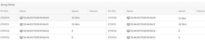
Create SAN Policy A
The SAN-A boot policy configures the SAN Primary's primary-target to be port CT0.FC0 on the Pure Storage cluster and SAN Primary's secondary-target to be port CT1.FC0 on the Pure Storage cluster. Similarly, the SAN Secondary’s primary-target should be port CT1.FC1 on the Pure Storage cluster and SAN Secondary's secondary-target should be port CT0.FC1 on the Pure Storage cluster.
Log into the storage controller and verify all the port information is correct. This information can be found in the Pure Storage GUI under System > Connections > Target Ports.
You have to create a SAN Primary (hba0) and a SAN Secondary (hba1) in SAN-A Boot Policy by entering WWPN of Pure Storage FC Ports as explained in the following section.
To create Boot Policies for the Cisco UCS environments, follow these steps:
1. Go to Cisco UCS Manager and then go to Servers > Policies > root > Sub Organization > FlashStack-CVD > Boot Policies. Right-click and select Create Boot Policy.
2. Enter SAN-A as the name of the boot policy.
3. Expand the Local Devices drop-down list and Choose Add CD/DVD. Expand the vHBAs drop-down list and Choose Add SAN Boot.
![]() The SAN boot paths and targets will include primary and secondary options in order to maximize resiliency and number of paths.
The SAN boot paths and targets will include primary and secondary options in order to maximize resiliency and number of paths.
4. In the Add SAN Boot dialog box, select Type as “Primary” and name vHBA as “hba0”. Click OK to add SAN Boot.

5. Select add SAN Boot Target to enter WWPN address of storage port. Keep 1 as the value for Boot Target LUN. Enter the WWPN for FC port CT0.FC0 of Pure Storage and add SAN Boot Primary Target.
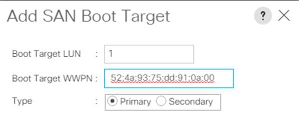
6. Add secondary SAN Boot target into same hba0, enter the boot target LUN as 1 and WWPN for FC port CT1.FC0 of Pure Storage, and add SAN Boot Secondary Target.
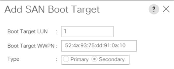
7. From the vHBA drop-down list and choose Add SAN Boot. In the Add SAN Boot dialog box, enter "hba1" in the vHBA field. Click OK to SAN Boot, then choose Add SAN Boot Target.

8. Keep 1 as the value for the Boot Target LUN. Enter the WWPN for FC port CT1.FC1 of Pure Storage and add SAN Boot Primary Target.
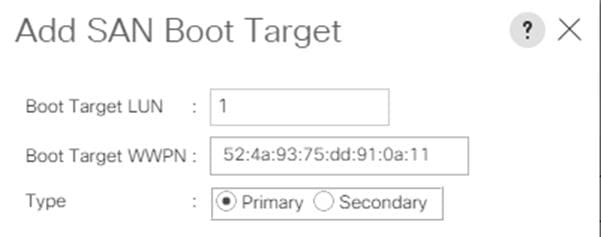
9. Add a secondary SAN Boot target into same vhba1 and enter the boot target LUN as 1 and WWPN for FC port CT0.FC1 of Pure Storage and add SAN Boot Secondary Target.
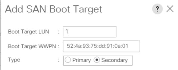
10. After creating the FC boot policies, you can view the boot order in the Cisco UCS Manager GUI. To view the boot order, navigate to Servers > Policies > Boot Policies. Click Boot Policy SAN-Boot-A to view the boot order in the right pane of the Cisco UCS Manager as shown below:
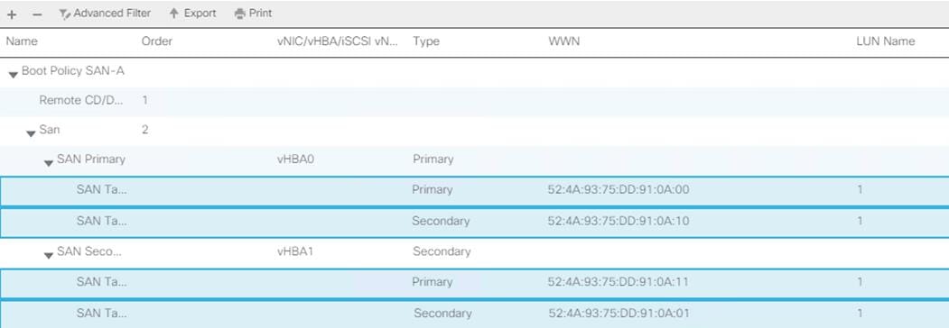
Create SAN Policy B
The SAN-B boot policy configures the SAN Primary's primary-target to be port CT0.FC6 on the Pure Storage cluster and SAN Primary's secondary-target to be port CT1.FC6 on the Pure Storage cluster. Similarly, the SAN Secondary’s primary-target should be port CT1.FC0 on the Pure Storage cluster and SAN Secondary's secondary-target should be port CT0.FC0 on the Pure Storage cluster.
Log into the storage controller and verify all the port information is correct. This information can be found in the Pure Storage GUI under System > Connections > Target Ports.
You have to create SAN Primary (vHBA0) and SAN Secondary (vHBA1) in SAN-B Boot Policy by entering WWPN of Pure Storage FC Ports as explained in the following section.
To create boot policies for the Cisco UCS environments, follow these steps:
1. Go to UCS Manager and then go to tab Servers > Policies > root > Sub Organization > FlashStack-CVD > Boot Policies.
2. Right-click and select Create Boot Policy. Enter SAN-B as the name of the boot policy.
3. Expand the Local Devices drop-down list and Choose Add CD/DVD. Expand the vHBAs drop-down list and choose Add SAN Boot.
![]() The SAN boot paths and targets include primary and secondary options in order to maximize resiliency and number of paths.
The SAN boot paths and targets include primary and secondary options in order to maximize resiliency and number of paths.
4. In the Add SAN Boot dialog box, select Type as “Primary” and name vHBA as “vHBA0”. Click OK to add SAN Boot.

5. Select Add SAN Boot Target to enter WWPN address of storage port. Keep 1 as the value for Boot Target LUN. Enter the WWPN for FC port CT0.FC2 of Pure Storage and add SAN Boot Primary Target.
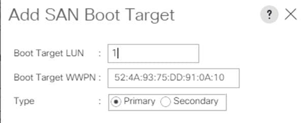
6. Add the secondary SAN Boot target into the same hba0; enter boot target LUN as 1 and WWPN for FC port CT0.FC0 of Pure Storage and add SAN Boot Secondary Target.
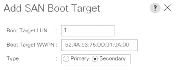
7. From the vHBA drop-down list, choose Add SAN Boot. In the Add SAN Boot dialog box, enter "hba1" in the vHBA field. Click OK to SAN Boot, then choose Add SAN Boot Target.

8. Keep 1 as the value for Boot Target LUN. Enter the WWPN for FC port CT0.FC1 of Pure Storage and Add SAN Boot Primary Target.
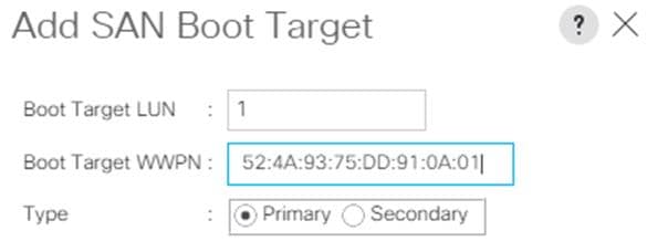
9. Add secondary SAN Boot target into same hba1 and enter boot target LUN as 1 and WWPN for FC port CT1.FC1 of Pure Storage and add SAN Boot Secondary Target.
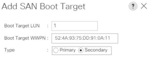
10. After creating the FC boot policies, you can view the boot order in the Cisco UCS Manager GUI. To view the boot order, navigate to Servers > Policies > Boot Policies. Click Boot Policy SAN-Boot-B to view the boot order in the right pane of the Cisco UCS Manager as shown below:
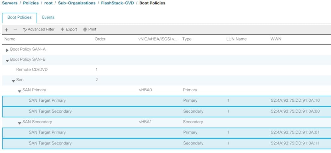
![]() For this solution, we created two Boot Policy as “SAN-A” and “SAN-B”. For thirty-two Cisco UCS B200 M5 blade servers, you will assign the first 16 Service Profiles with SAN-A to the first 16 servers and the remaining 16 Service Profiles with SAN-B to the remaining 16 servers as explained in the following section.
For this solution, we created two Boot Policy as “SAN-A” and “SAN-B”. For thirty-two Cisco UCS B200 M5 blade servers, you will assign the first 16 Service Profiles with SAN-A to the first 16 servers and the remaining 16 Service Profiles with SAN-B to the remaining 16 servers as explained in the following section.
Configure and Create a Service Profile Template
Service profile templates enable policy-based server management that helps ensure consistent server resource provisioning suitable to meet predefined workload needs.
You will create two Service Profile templates; the first Service profile template “VDI-CVD01” uses the boot policy “SAN-A” and the second Service profile template “VDI-CVD02” uses the boot policy “SAN-B” to utilize all the FC ports from Pure Storage for high-availability in case any FC links go down.
You will create the first VDI-CVD01 as explained in the following section.
Create Service Profile Template
To create a service profile template, follow these steps:
1. In the Cisco UCS Manager, go to Servers > Service Profile Templates > root Sub Organization > FlashStack-CVD > and right-click to “Create Service Profile Template” as shown below.
2. Enter the Service Profile Template name, select the UUID Pool that was created earlier, and click Next.
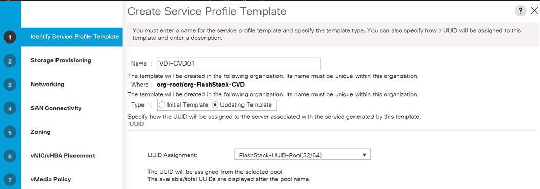
3. Select Local Disk Configuration Policy to SAN-Boot as No Local Storage.
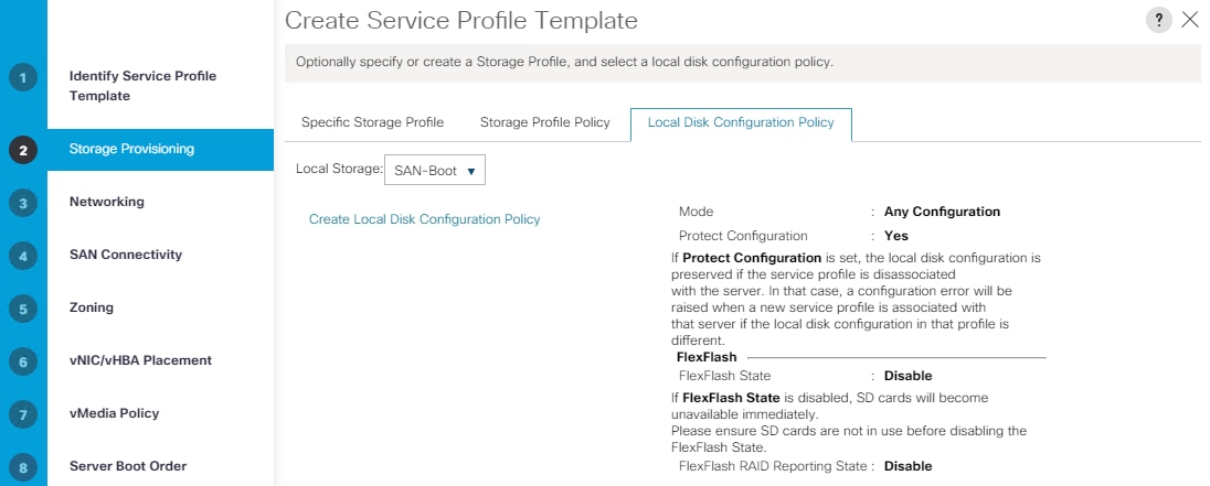
4. In the networking window, select Expert and click Add to create vNICs. Add one or more vNICs that the server should use to connect to the LAN.
Now there are two vNIC in the create vNIC menu; you provided a name to the first vNIC as “eth0” and the second vNIC as “eth1.”
5. Select vNIC-Template-A for the vNIC Template and select VMware for the Adapter Policy as shown below.
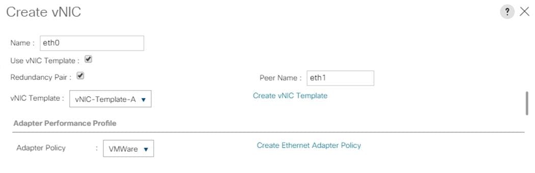
6. Select vNIC-Template-B for the vNIC Template, created with the name eth1. Select VMware for the vNIC “eth1” for the Adapter Policy.
![]() eth0 and eth1 vNICs are created so that the servers can connect to the LAN.
eth0 and eth1 vNICs are created so that the servers can connect to the LAN.
7. When the vNICs are created, you need to create vHBAs. Click Next.
8. In the SAN Connectivity menu, select “Expert” to configure as SAN connectivity. Select WWNN (Worldwide Node Name) pool, which you created previously. Click “Add” to add vHBAs.
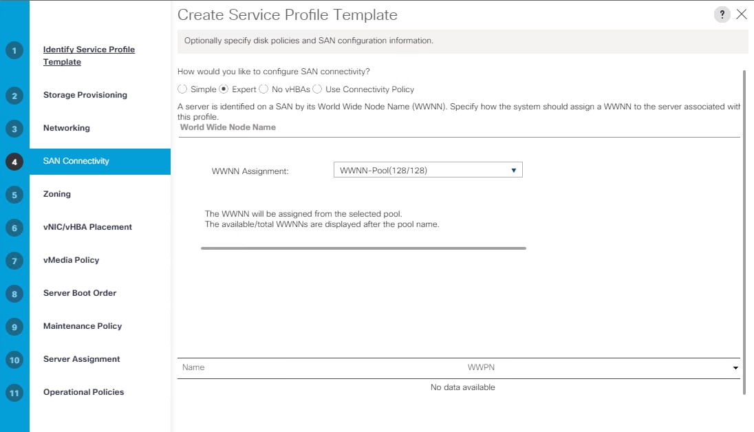
The following four HBAs were created:
· vHBA0 using vHBA Template vHBA-A
· vHBA1 using vHBA Template vHBA-B
· vHBA2 using vHBA Template vHBA-A
· vHBA3 using vHBA Template vHBA-B
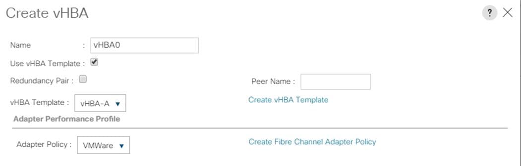
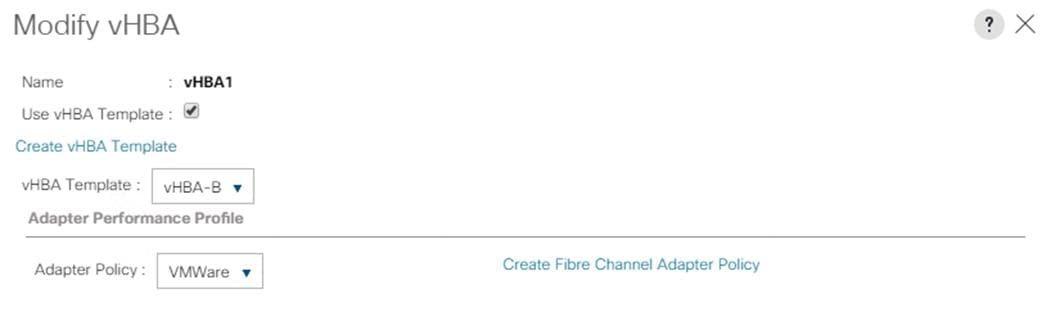
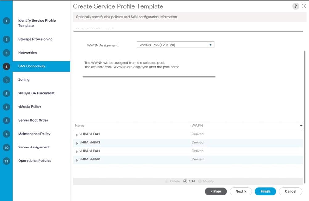
9. Skip zoning; for this FlashStack Configuration, the Cisco MDS 9132T 32-Gb is used for zoning.
10. Select the default option as Let System Perform Placement in the Placement Selection menu.
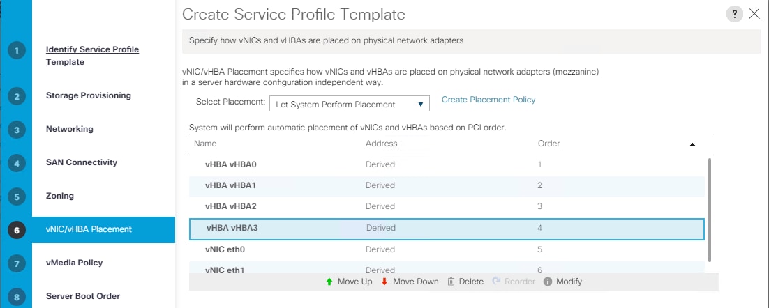
11. For the Server Boot Policy, select “SAN-A” as Boot Policy which you created earlier.
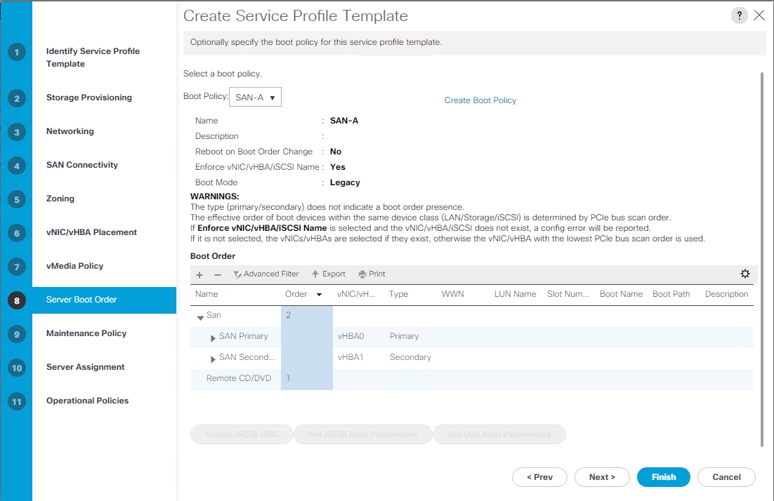
The default setting was retained for the remaining maintenance and assignment policies in the configuration. However, they may vary from site-to-site depending on workloads, best practices, and policies. For example, we created a maintenance policy, BIOS policy, Power Policy, as detailed below.
12. Select UserAck maintenance policy, which requires user acknowledgement prior rebooting server when making changes to policy or pool configuration tied to a service profile.
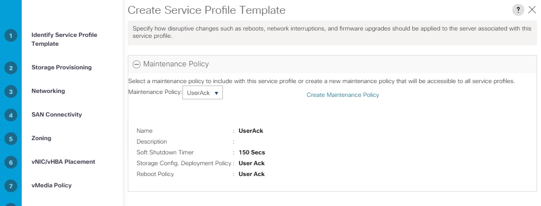
13. Select Server Pool policy to automatically assign service profile to a server that meets the requirement for server qualification based on the pool configuration.
14. On the same page; you can configure “Host firmware Package Policy” which helps to keep the firmware in sync when associated to server.
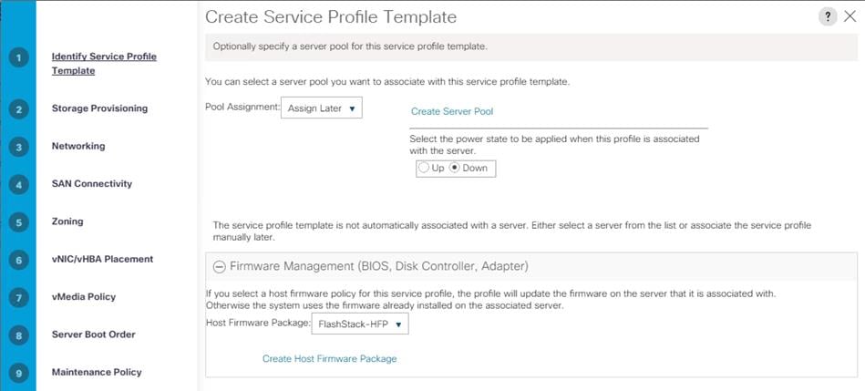
15. On the Operational Policy page, we configured BIOS policy for B200 M5 blade server, Power Control Policy with “NoPowerCap” for maximum performance and Graphics Card Policy for B200 M5 server configured with NVidia P6 GPU card.
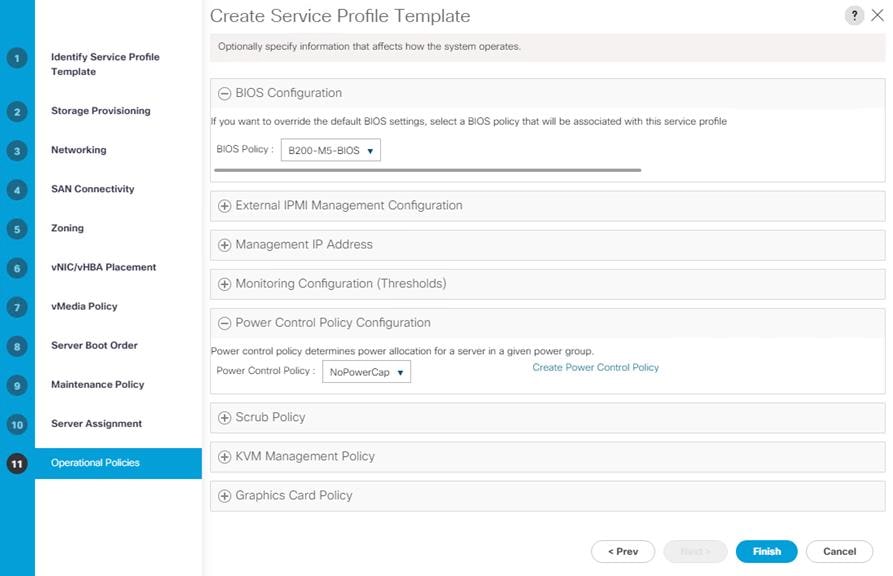
16. Click Next and then click Finish to create service profile template as “VDI-CVD01.”
Clone Service Profile Template
To clone the Service Profile template, follow these steps:
1. In the service profile template VDI-CVD02, modify the Boot Policy as “SAN-B” to use all the remaining FC paths of storage for high availability.
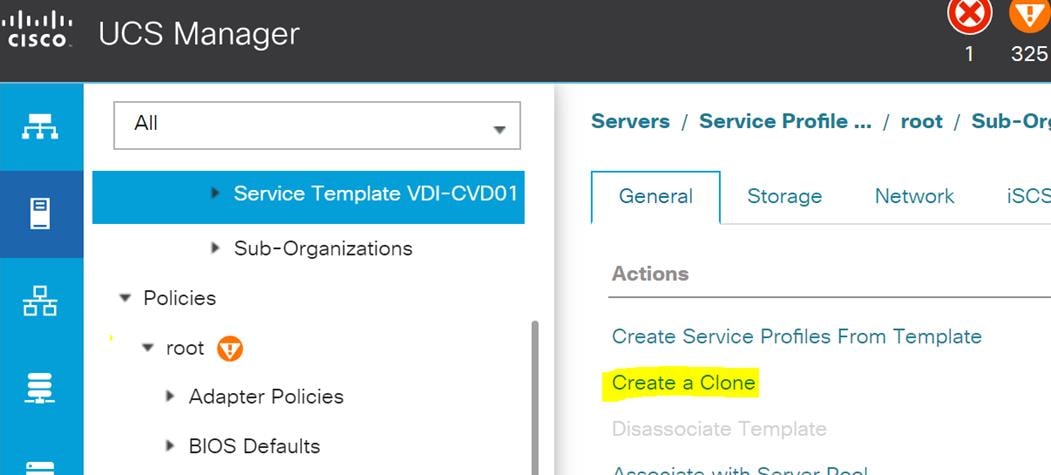
2. Enter name to create Clone from existing Service Profile template. Click OK.
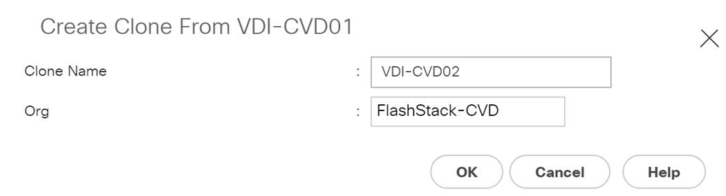
![]() This VDI-CVD02 service profile template will be used to create the remaining sixteen service profiles for VDI workload and Infrastructure server02.
This VDI-CVD02 service profile template will be used to create the remaining sixteen service profiles for VDI workload and Infrastructure server02.
3. To change boot order from SAN-A to SAN-B for VDI-CVD02, click Cloned Service Profile template > Select Boot Order tab. Click Modify Boot Policy.
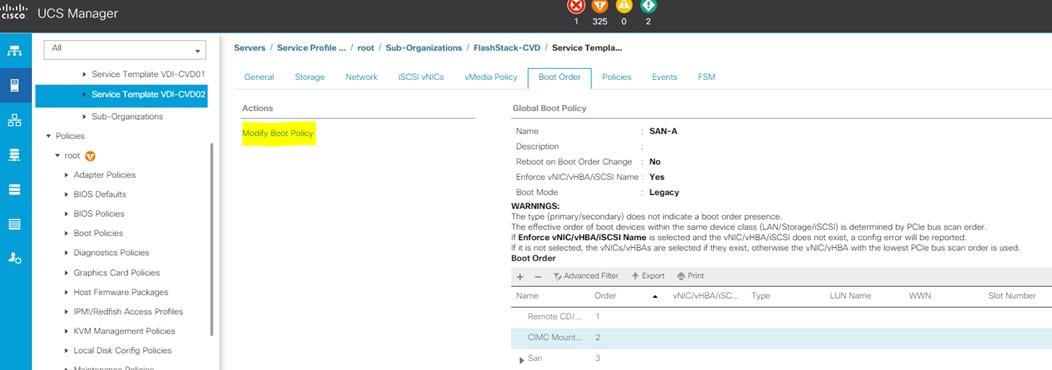
4. From the drop-down list select “SAN-B” as Boot Policy, click OK.
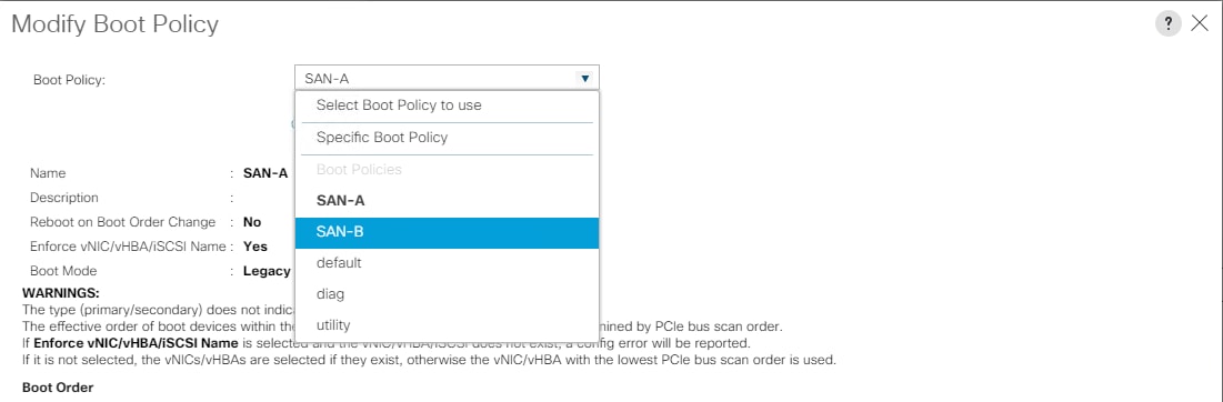
You have now created the Service Profile template “VDI-CVD01” and “VDI-CVD02” with each having four vHBAs and two vNICs.
Create Service Profiles from Template and Associate to Servers
Create Service Profiles from Template
You will create sixteen Service profiles from the VDI-CVD01 template and sixteen Service profiles from the VDI-CVD02 template as explained in the following sections.
For the first fifteen workload Nodes and Infrastructure Node 01, you will create sixteen Service Profiles from Template “VDI-CVD01.” The remaining fifteen workload Nodes and Infrastructure Node 02, will require creating another sixteen Service Profiles from Template “VDI-CVD02.”
To create first four Service Profiles from Template, follow these steps:
1. Go to tab Servers > Service Profiles > root > Sub-Organization > FlashStack-CVD and right-click “Create Service Profiles from Template.”
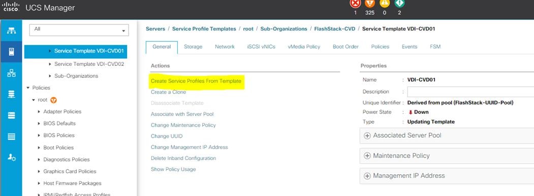
2. Select “VDI-CVD01” for the Service profile template which you created earlier and name the service profile “VDI-HostX.” To create four service profiles, enter 16 for the Number of Instances, as 16 as shown below. This process will create service profiles “VDI-HOST1”, “VDI-HOST2”, …. and “VDI-HOST16.”
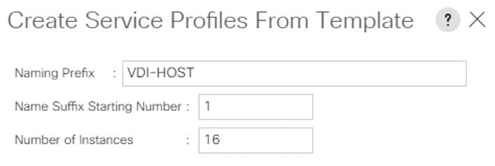
3. Create the remaining four Service Profiles “VDI-HOST17”, “VDI-HOST18”, …. and “VDI-HOST32” from Template “VDI-CVD02.”
4. When the service profiles are created, the association of Service Profile starts automatically to servers based on the Server Pool Policies.
5. Rename the Service Profiles at Chassis 3/8 as VDI-Infra01 and Service Profile on 4/8 as VDI-Infra02. Rename rest as necessary to have VDI-Host1to VDI-Host30.
The Service Profile association can be verified in Cisco UCS Manager > Servers > Service Profiles. Different tabs can provide details on Service profile association based on Server Pools Policy, Service Profile Template to which Service Profile is tied to, and so on.
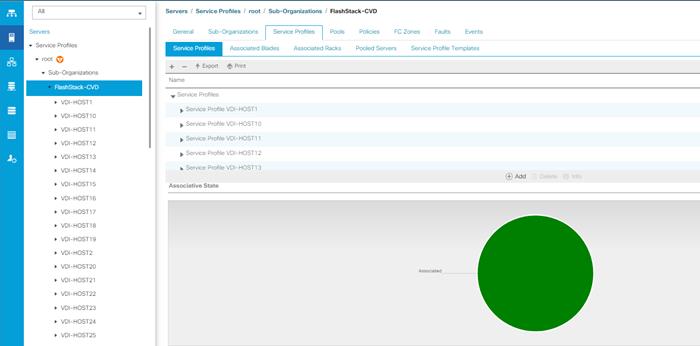
Configure Cisco Nexus 93180YC-FX Switches
The following section details the steps for the Nexus 93180YC-FX switch configuration. The details of “show run” output are listed in the Appendix.
Configure Global Settings for Cisco Nexus A and Cisco Nexus B
To set global configuration, follow these steps on both the Nexus switches:
1. Log in as admin user into the Nexus Switch A and run the following commands to set global configurations and jumbo frames in QoS:
conf terminal sh
policy-map type network-qos jumbo
class type network-qos class-default
mtu 9216
exit
class type network-qos class-fcoe
pause no-drop
mtu 2158
exit
exit
system qos
service-policy type network-qos jumbo
exit
copy run start
2. Log in as admin user into the Nexus Switch B and run the same above commands to set global configurations and jumbo frames in QoS.
Configure VLANs for Cisco Nexus A and Cisco Nexus B Switches
To create the necessary virtual local area networks (VLANs), follow these steps on both Nexus switches. We created VLAN 70, 71, 72, 73 and 76. The details of the “show run” output are listed in the Appendix.
1. Log in as admin user into the Nexus Switch A.
2. Create VLAN 70:
config terminal
VLAN 70
name InBand-Mgmt
no shutdown
exit
copy running-config startup-config
exit
3. Log in as admin user into the Nexus Switch B and create VLANs
Virtual Port Channel (vPC) Summary for Data and Storage Network
In the Cisco Nexus 93180YC-FX switch topology, a single vPC feature is enabled to provide HA, faster convergence in the event of a failure, and greater throughput. Cisco Nexus 93180YC-FX vPC configurations with the vPC domains and corresponding vPC names and IDs for Oracle Database Servers is listed in Table 5 .
| vPC Domain |
vPC Name |
vPC ID |
| 70 |
Peer-Link |
1 |
| 70 |
vPC Port-Channel to FI |
11 |
| 70 |
vPC Port-Channel to FI |
12 |
As listed in Table 5 , a single vPC domain with Domain ID 70 is created across two Cisco Nexus 93180YC-FX member switches to define vPC members to carry specific VLAN network traffic. In this topology, we defined a total number of 3 vPCs:
· vPC ID 1 is defined as Peer link communication between two Nexus switches in Fabric A and B.
· vPC IDs 11 and 12 are defined for traffic from Cisco UCS fabric interconnects.
Cisco Nexus 93180YC-FX Switch Cabling Details
The following tables list the cabling information.
Table 6 Cisco Nexus 93180YC-FX-A Cabling Information
| Local Device |
Local Port |
Connection |
Remote Device |
Remote Port |
| Cisco Nexus 93180YC-FX Switch A
|
Eth1/51 |
40Gbe |
Cisco UCS fabric interconnect A |
Eth1/49 |
| Eth1/52 |
40Gbe |
Cisco UCS fabric interconnect B |
Eth1/49 |
|
| Eth1/53 |
40Gbe |
Cisco Nexus 93180YC-FX B |
Eth1/53 |
|
| Eth1/54 |
40Gbe |
Cisco Nexus 93180YC-FX B |
Eth1/54 |
|
| MGMT0 |
1Gbe |
Gbe management switch |
Any |
Table 7 Cisco Nexus 93180YC-FX-B Cabling Information
| Local Device |
Local Port |
Connection |
Remote Device |
Remote Port |
| Cisco Nexus 93180YC-FX Switch B
|
Eth1/51 |
40Gbe |
Cisco UCS fabric interconnect A |
Eth1/50 |
| Eth1/52 |
40Gbe |
Cisco UCS fabric interconnect B |
Eth1/50 |
|
| Eth1/53 |
40Gbe |
Cisco Nexus 93180YC-FX A |
Eth1/53 |
|
| Eth1/54 |
40Gbe |
Cisco Nexus 93180YC-FX |
Eth1/54 |
|
| MGMT0 |
Gbe |
Gbe management switch |
Any |
Cisco UCS Fabric Interconnect 6332-16UP Cabling
The following tables list the FI 6332-16UP cabling information.
Table 8 Cisco UCS Fabric Interconnect (FI) A Cabling Information
| Local Device |
Local Port |
Connection |
Remote Device |
Remote Port |
| Cisco UCS FI-6332-16UP-A |
FC 1/1 |
32G FC |
Cisco MDS 9132T 32-Gb-A |
FC 1/13 |
| FC 1/2 |
32G FC |
Cisco MDS 9132T 32-Gb-A |
FC 1/14 |
|
| FC 1/3 |
32G FC |
Cisco MDS 9132T 32-Gb-A |
FC 1/15 |
|
| FC ¼ |
32G FC |
Cisco MDS 9132T 32-Gb-A |
FC 1/16 |
|
| Eth1/17-24 |
40Gbe |
UCS 5108 Chassis IOM-A Chassis 1-4 |
IO Module Port1-2 |
|
| Eth1/49 |
40Gbe |
Cisco Nexus 93180YC-FX Switch A |
Eth1/52 |
|
| Eth1/50 |
40Gbe |
Cisco Nexus 93180YC-FX Switch B |
Eth1/52 |
|
| Mgmt 0 |
1Gbe |
Management Switch |
Any |
|
| L1 |
1Gbe |
Cisco UCS FI - A |
L1 |
|
| L2 |
1Gbe |
Cisco UCS FI - B |
L2 |
Table 9 Cisco UCS Fabric Interconnect (FI) B Cabling Information
| Local Device |
Local Port |
Connection |
Remote Device |
Remote Port |
| Cisco UCS FI-6332-16UP-B |
FC 1/1 |
32G FC |
Cisco MDS 9132T 32-Gb-B |
FC 1/13 |
| FC 1/2 |
32G FC |
Cisco MDS 9132T 32-Gb-B |
FC 1/14 |
|
| FC 1/3 |
32G FC |
Cisco MDS 9132T 32-Gb-B |
FC 1/15 |
|
| FC ¼ |
32G FC |
Cisco MDS 9132T 32-Gb-B |
FC 1/16 |
|
| Eth1/17-24 |
40Gbe |
UCS 5108 Chassis IOM-B Chassis 1-4 |
IO Module Port1-2 |
|
| Eth1/49 |
40Gbe |
Cisco Nexus 93180YC-FX Switch A |
Eth1/51 |
|
| Eth1/50 |
40Gbe |
Cisco Nexus 93180YC-FX Switch B |
Eth1/51 |
|
| Mgmt 0 |
1Gbe |
Management Switch |
Any |
|
| L1 |
1Gbe |
Cisco UCS FI - A |
L1 |
|
| L2 |
1Gbe |
Cisco UCS FI - B |
L2 |
Create vPC Peer-Link Between the Two Nexus Switches
To create the vPC Peer-Link, follow these steps:
1. Log in as “admin” user into the Nexus Switch A.
![]() For vPC 1 as Peer-link, we used interfaces 53-54 for Peer-Link. You may choose the appropriate number of ports for your needs.
For vPC 1 as Peer-link, we used interfaces 53-54 for Peer-Link. You may choose the appropriate number of ports for your needs.
2. Create the necessary port channels between devices, on both Nexus Switches:
config terminal
feature vpc
feature lacp
vpc domain 1
peer-keepalive destination 10.29.164.234 source 10.29.164.233
exit
interface port-channel 70
description VPC peer-link
switchport mode trunk
switchport trunk allowed VLAN 1,70-76
spanning-tree port type network
vpc peer-link
exit
interface Ethernet1/53
description vPC-PeerLink
switchport mode trunk
switchport trunk allowed VLAN 1, 70-76
channel-group 70 mode active
no shutdown
exit
interface Ethernet1/54
description vPC-PeerLink
switchport mode trunk
switchport trunk allowed VLAN 1, 70-76
channel-group 70 mode active
no shutdown
exit
3. Log in as admin user into the Nexus Switch B and repeat the above steps to configure second nexus switch.
![]() Make sure to change peer-keepalive destination and source IP address appropriately for Nexus Switch B.
Make sure to change peer-keepalive destination and source IP address appropriately for Nexus Switch B.
Create vPC Configuration Between Nexus 93180YC-FX and Fabric Interconnects
Create and configure vPC 11 and 12 for data network between the Nexus switches and Fabric Interconnects.
To create the necessary port channels between devices, follow these steps on both Nexus Switches:
1. Log in as admin user into Nexus Switch A and enter the following:
config Terminal
interface port-channel11
description FI-A-Uplink
switchport mode trunk
switchport trunk allowed VLAN 1,70-76
spanning-tree port type edge trunk
vpc 11
no shutdown
exit
interface port-channel12
description FI-B-Uplink
switchport mode trunk
switchport trunk allowed VLAN 1,70-76
spanning-tree port type edge trunk
vpc 12
no shutdown
exit
interface Ethernet1/51
description FI-A-Uplink
switch mode trunk
switchport trunk allowed vlan 1,70-76
spanning-tree port type edge trunk
mtu 9216
channel-group 11 mode active
no shutdown
exit
interface Ethernet1/52
description FI-B-Uplink
switch mode trunk
switchport trunk allowed vlan 1,70-76
spanning-tree port type edge trunk
mtu 9216
channel-group 12 mode active
no shutdown
exit
copy running-config startup-config
2. Log in as admin user into the Nexus Switch B and complete the following for the second switch configuration:
config Terminal
interface port-channel11
description FI-A-Uplink
switchport mode trunk
switchport trunk allowed VLAN 1,70-76
spanning-tree port type edge trunk
vpc 11
no shutdown
exit
interface port-channel12
description FI-B-Uplink
switchport mode trunk
switchport trunk allowed VLAN 1,70-76
spanning-tree port type edge trunk
vpc 12
no shutdown
exit
interface Ethernet1/51
description FI-A-Uplink
switch mode trunk
switchport trunk allowed vlan 1,70-76
spanning-tree port type edge trunk
mtu 9216
channel-group 11 mode active
no shutdown
exit
interface Ethernet1/52
description FI-B-Uplink
switch mode trunk
switchport trunk allowed vlan 1,70-76
spanning-tree port type edge trunk
mtu 9216
channel-group 12 mode active
no shutdown
exit
copy running-config startup-config
Verify All vPC Status is Up on Both Cisco Nexus Switches
Figure 44 shows the verification of the vPC status on both Cisco Nexus Switches.
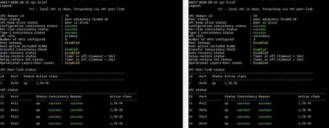
Cisco MDS 9132T 32-Gb FC Switch Configuration
This section details the configuration for the Cisco MDS 9132T 32 Gb FC switch.
Table 10 Cisco MDS 9132T-A Cabling Information
| Local Device |
Local Port |
Connection |
Remote Device |
Remote Port |
| Cisco MDS 9132T-A |
FC1/9 |
32Gb FC |
Pure Storage FlashArray//X70 R2 Controller 00 |
CT0.FC1 |
| FC1/10 |
32Gb FC |
Pure Storage FlashArray//X70 R2 Controller 01 |
CT1.FC1 |
|
| FC1/13 |
32Gb FC |
Cisco 6332-16UP Fabric Interconnect-A |
FC1/1 |
|
| FC1/14 |
32Gb FC |
Cisco 6332-16UP Fabric Interconnect-A |
FC1/2 |
|
| FC1/15 |
32Gb FC |
Cisco 6332-16UP Fabric Interconnect-A |
FC1/3 |
|
| FC1/16 |
32Gb FC |
Cisco 6332-16UP Fabric Interconnect-A |
FC1/4 |
Table 11 Cisco MDS 9132T-B Cabling Information
| Local Device |
Local Port |
Connection |
Remote Device |
Remote Port |
| Cisco MDS 9132T-B |
FC1/9 |
32Gb FC |
Pure Storage FlashArray//X70 R2 Controller 01 |
CT1.FC0 |
| FC1/10 |
32Gb FC |
Pure Storage FlashArray//X70 R2 Controller 00 |
CT0.FC0 |
|
| FC1/13 |
32Gb FC |
Cisco 6332-16UP Fabric Interconnect-B |
FC1/1 |
|
| FC1/14 |
32Gb FC |
Cisco 6332-16UP Fabric Interconnect-B |
FC1/2 |
|
| FC1/15 |
32Gb FC |
Cisco 6332-16UP Fabric Interconnect-B |
FC1/3 |
|
| FC1/16 |
32Gb FC |
Cisco 6332-16UP Fabric Interconnect-B |
FC1/4 |
Pure Storage FlashArray//X70 R2 to MDS SAN Fabric Connectivity
Pure Storage FlashArray//X70 R2 to MDS A and B Switches using VSAN 100 for Fabric A and VSAN 101 Configured for Fabric B
In this solution, two ports (ports FC1/9 abd FC1/10) of MDS Switch A and two ports (ports FC1/9 abd FC1/10) of MDS Switch B connected to Pure Storage System as shown in Table 12 . All ports connected to the Pure Storage Array carry 32 Gb/s FC Traffic.
Table 12 MDS 9132T 32-Gb switch Port Connection to Pure Storage System
| Local Device |
Local Port |
Connection |
Remote Device |
Remote Port |
| MDS Switch A |
FC1/9 |
32Gb FC |
Pure Storage FlashArray//X70 R2 Controller 0 |
CT0.FC1 |
| FC1/10 |
32Gb FC |
Pure Storage FlashArray//X70 R2 Controller 1 |
CT1.FC1 |
|
| MDS Switch B |
FC1/9 |
32Gb FC |
Pure Storage FlashArray//X70 R2 Controller 1 |
CT1.FC0 |
| FC1/10 |
32Gb FC |
Pure Storage FlashArray//X70 R2 Controller 0 |
CT0.FC0 |
Configure Feature for MDS Switch A and MDS Switch B
To set feature on MDS Switches, follow these steps on both MDS switches:
1. Log in as admin user into MDS Switch A:
config terminal
feature npiv
feature telnet
switchname FlashStack-MDS-A
copy running-config startup-config
2. Log in as admin user into MDS Switch B. Repeat the steps above on MDS Switch B.
Configure VSANs for MDS Switch A and MDS Switch B
To create VSANs, follow these steps on both MDS switches:
1. Log in as admin user into MDS Switch A. Create VSAN 100 for Storage Traffic:
config terminal
VSAN database
vsan 100
vsan 100 interface fc 1/9-16
exit
interface fc 1/9-16
switchport trunk allowed vsan 100
switchport trunk mode off
port-license acquire
no shutdown
exit
copy running-config startup-config
2. Log in as admin user into MDS Switch B. Create VSAN 101 for Storage:
config terminal
VSAN database
vsan 101
vsan 101 interface fc 1/9-16
exit
interface fc 1/9-16
switchport trunk allowed vsan 101
switchport trunk mode off
port-license acquire
no shutdown
exit
copy running-config startup-config
Add FC Uplink Ports to Corresponding VSAN on Fabric Interconnect
To add the FC Ports to the corresponding VSAN, follow these steps:
1. In Cisco UCS Manager, in the Equipment tab, select Fabric Interconnects > Fabric Interconnect A > Fixed Module > FC Ports.
2. Select FC Port 1, drop-down list for VSAN, and select VSAN 100.
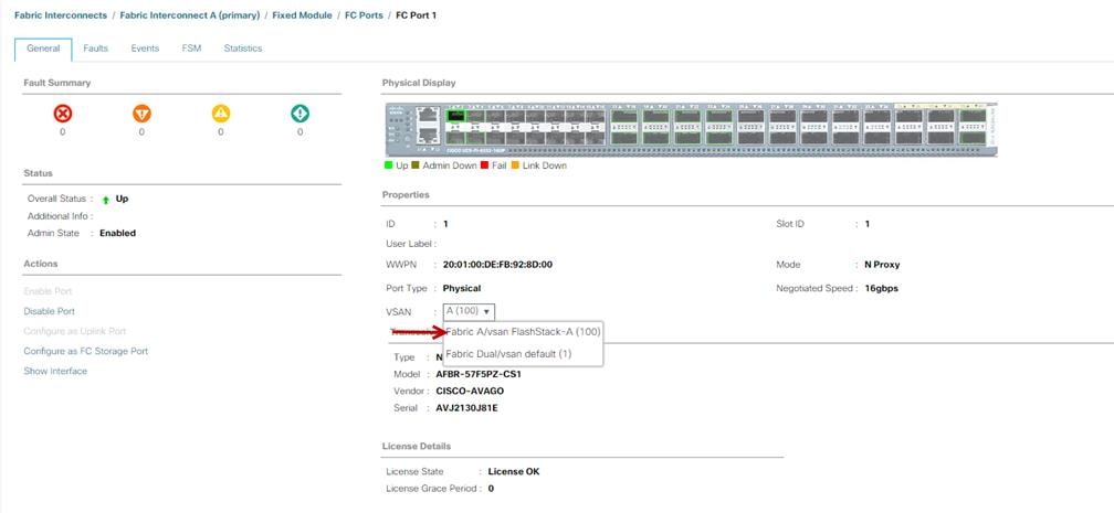
3. Repeat these steps to Add FC Port 1-4 to VSAN 100 on Fabric A and FC Port 1-4 to VSAN 101 on Fabric B.
Create and Configure Fiber Channel Zoning
This procedure sets up the Fibre Channel connections between the Cisco MDS 9132T 32-Gb switches, the Cisco UCS Fabric Interconnects, and the Pure Storage FlashArray systems.
![]() Before you configure the zoning details, decide how many paths are needed for each LUN and extract the WWPN numbers for each of the HBAs from each server. We used 4 HBAs for each Server. Two HBAs (HBA0 and HBA2) are connected to MDS Switch-A and other two HBAs (HBA1 and HBA3) are connected to MDS Switch-B.
Before you configure the zoning details, decide how many paths are needed for each LUN and extract the WWPN numbers for each of the HBAs from each server. We used 4 HBAs for each Server. Two HBAs (HBA0 and HBA2) are connected to MDS Switch-A and other two HBAs (HBA1 and HBA3) are connected to MDS Switch-B.
To create and configure the fiber channel zoning, follow these steps:
1. Log into the Cisco UCS Manager > Servers > Service Profiles > VDI-Host, then click the HBA's tab to get the WWPN of HBA's as shown in the screenshot below:
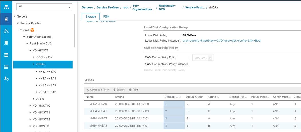
2. Connect to the Pure Storage System and extract the WWPN of FC Ports connected to the Cisco MDS Switches. We have connected 4 FC ports from Pure Storage System to Cisco MDS Switches. FC ports CT0.FC1, CT1.FC1 are connected to MDS Switch-A and similarly FC ports CT1.FC0, CT0.FC0 are connected to MDS Switch-B.
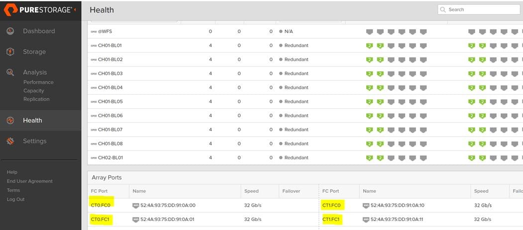
Create Device Aliases for Fiber Channel Zoning
Cisco MDS Switch A
To configure device aliases and zones for the SAN boot paths as well as the datapaths of MDS switch A, follow these steps. The Appendix section regarding MDS 9132T 32-Gb switch provides detailed information about the “show run” configuration.
1. Log in as admin user and run the following commands:
conf t
device-alias database
device-alias name VDI-Host01-HBA0 pwwn 20:00:00:25:B5:AA:17:00
device-alias name VDI-Host01-HBA2 pwwn 20:00:00:25:B5:AA:17:01
device-alias name FLASHSTACK-X-CT0-FC0 pwwn 52:4a:93:75:dd:91:0a:00
device-alias name FLASHSTACK-X-CT0-FC1 pwwn 52:4a:93:75:dd:91:0a:01
device-alias name FLASHSTACK-X-CT1-FC1 pwwn 52:4a:93:75:dd:91:0a:11
device-alias name FLASHSTACK-X-CT1-FC0 pwwn 52:4a:93:75:dd:91:0a:10
Cisco MDS Switch B
To configure device aliases and zones for the SAN boot paths as well as datapaths of MDS switch B, follow these steps:
1. Log in as admin user and run the following commands:
conf t
device-alias database
device-alias name VDI-Host01-HBA1 pwwn 20:00:00:25:B5:AA:17:00
device-alias name VDI-Host01-HBA3 pwwn 20:00:00:25:B5:AA:17:01
device-alias name FLASHSTACK-X-CT0-FC0 pwwn 52:4a:93:75:dd:91:0a:00
device-alias name FLASHSTACK-X-CT0-FC1 pwwn 52:4a:93:75:dd:91:0a:01
device-alias name FLASHSTACK-X-CT1-FC1 pwwn 52:4a:93:75:dd:91:0a:11
device-alias name FLASHSTACK-X-CT1-FC0 pwwn 52:4a:93:75:dd:91:0a:10
Create Zoning
Cisco MDS Switch A
To configure zones for the MDS switch A, follow these steps:
1. Create a zone for each service profile.
2. Login as admin user and create the zone as shown below:
conf t
zone name FlaskStack-VDI-CVD-Host01 vsan 100
member pwwn 52:4a:93:75:dd:91:0a:00
member pwwn 52:4a:93:75:dd:91:0a:01
member pwwn 52:4a:93:75:dd:91:0a:11
member pwwn 52:4a:93:75:dd:91:0a:10
member pwwn 20:00:00:25:B5:AA:17:00
member pwwn 20:00:00:25:B5:AA:17:01
conf t
zoneset name FlashStack-VDI-CVD vsan 100
member FlaskStack-VDI-CVD-Host01
3. After the zone for the Cisco UCS service profile has been created, create the zone set and add the necessary members:
conf t
zoneset name FlashStack-VDI-CVD vsan 100
member FlaskStack-VDI-CVD-Host01
4. Activate the zone set by running following commands:
zoneset activate name FlashStack-VDI-CVD vsan 100
exit
copy running-config startup-config
Configure Pure Storage FlashArray//X70 R2
The design goal of the reference architecture is to best represent a real-world environment as closely as possible. The approach included the features of Cisco UCS to rapidly deploy stateless servers and use Pure Storage FlashArray’s boot LUNs to provision the O.S on top of Cisco UCS. Zoning was performed on the Cisco MDS 9132T 32-Gb switches to enable the initiators discover the targets during boot process.
A Service Profile was created within Cisco UCS Manager to deploy the thirty-two servers quickly with a standard configuration. SAN boot volumes for these servers were hosted on the same Pure Storage FlashArray//X70 R2. Once the stateless servers were provisioned, following process was performed to enable Rapid deployment of thirty-two nodes.
Each Server node has dedicated single LUN to install operating system and all the thirty-two server node was booted off SAN. For this solution, we have installed vSphere ESXi 6.7 U1 Cisco Custom ISO on this LUNs to create thirty node based Citrix Virtual Apps and Desktops 7.15 LTSR CU3 solution.
Using logical servers that are disassociated from the physical hardware removes many limiting constraints around how servers are provisioned. Cisco UCS Service Profiles contain values for a server's property settings, including virtual network interface cards (vNICs), MAC addresses, boot policies, firmware policies, fabric connectivity, external management, and HA information. The service profiles represent all the attributes of a logical server in Cisco UCS model. By abstracting these settings from the physical server into a Cisco Service Profile, the Service Profile can then be deployed to any physical compute hardware within the Cisco UCS domain. Furthermore, Service Profiles can, at any time, be migrated from one physical server to another. Furthermore, Cisco is the only hardware provider to offer a truly unified management platform, with Cisco UCS Service Profiles and hardware abstraction capabilities extending to both blade and rack servers.
In addition to the service profiles, the use of Pure Storage’s FlashArray’s with SAN boot policy provides the following benefits:
· Scalability - Rapid deployment of new servers to the environment in a very few steps.
· Manageability - Enables seamless hardware maintenance and upgrades without any restrictions. This is a huge benefit in comparison to another appliance model like Exadata.
· Flexibility - Easy to repurpose physical servers for different applications and services as needed.
· Availability - Hardware failures are not impactful and critical. In rare case of a server failure, it is easier to associate the logical service profile to another healthy physical server to reduce the impact.
Configure Host
Before using a volume (LUN) on a host, the host has to be defined on Pure Storage FlashArray. To set up a host follow these steps:
1. Log into FlashArray dashboard.
2. In the PURE GUI, go to Storage tab.
3. Under Hosts option in the left frame, click the + sign to create a host.
4. Enter the name of the host or select Create Multiple and click Create. This will create a Host entry(s) under the Hosts category.
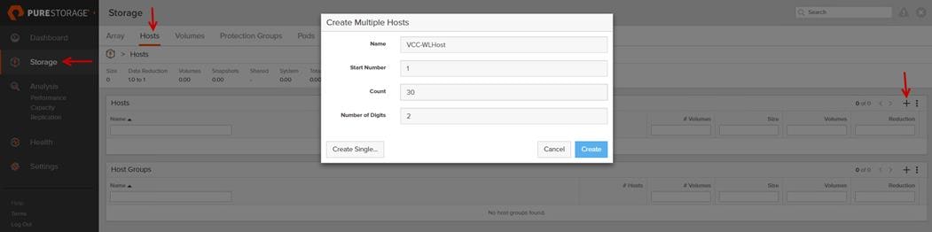
5. To update the host with the connectivity information by providing the Fibre Channel WWNs or iSCSI IQNs, click the Host that was created.
6. In the host context, click the Host Ports tab and click the settings button and select “Configure Fibre Channel WWNs” which will display a window with the available WWNs in the left side.
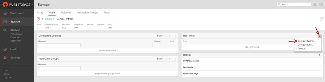
7. Select the list of WWNs that belongs to the host in the next window and click “Confirm.”
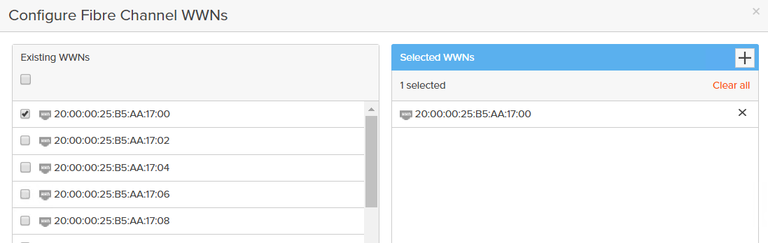
![]() Make sure the zoning has been setup to include the WWNs details of the initiators along with the target, without which the SAN boot will not work.
Make sure the zoning has been setup to include the WWNs details of the initiators along with the target, without which the SAN boot will not work.
![]() WWNs will appear only if the appropriate FC connections were made and the zones were setup on the underlying FC switch.
WWNs will appear only if the appropriate FC connections were made and the zones were setup on the underlying FC switch.
Configure Volume
To configure a volume, follow these steps:
1. Go to the Storage tab > Volumes > and click the + sign to “Create Volume.”
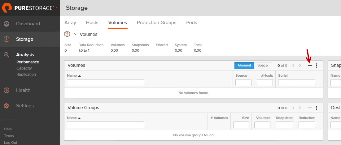
2. Provide the name of the volume, size, choose the size type (KB, MB, GB, TB, PB) and click Create to create the volume. Example creating 32 SAB boot Volume for 32 B200 M5 server configured in this solution.
3. Two for Infrastructure and remaining thirty Servers for Citrix Virtual Apps and Desktops workload test.
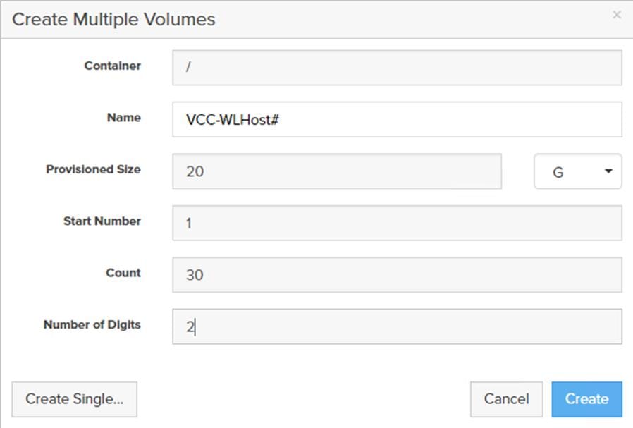
4. Attach the volume to a host by going to the “Connected Hosts and Host Groups” tab under the volume context menu.
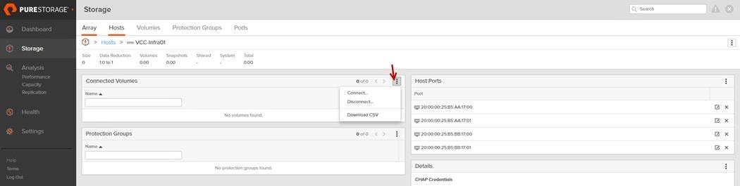
5. Select Connect. In the Connect Volumes to Host wizard select SAN-BootXX volume, click Connect.
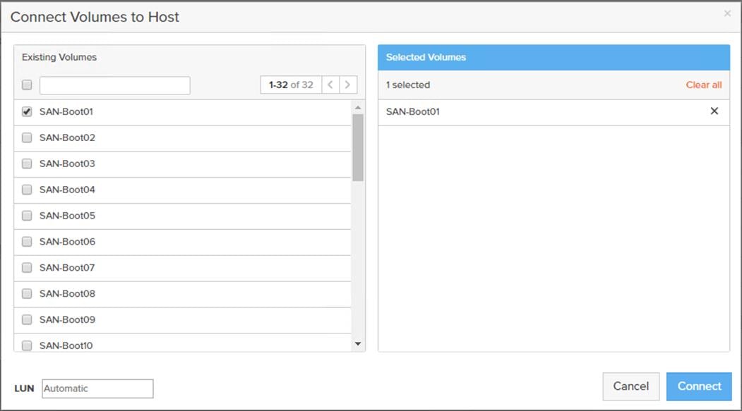
![]() Make sure the SAN Boot Volumes has the LUN ID “1” since this is important while configuring Boot from SAN. You will also configure the LUN ID as “1” when configuring Boot from SAN policy in Cisco UCS Manager.
Make sure the SAN Boot Volumes has the LUN ID “1” since this is important while configuring Boot from SAN. You will also configure the LUN ID as “1” when configuring Boot from SAN policy in Cisco UCS Manager.
More LUNs can be connected by adding a connection to existing or new volume(s) to an existing node.
Install and Configure VMware ESXi 6.7
This section explains how to install VMware ESXi 6.7 Update1 in an environment.
There are several methods to install ESXi in a VMware environment. These procedures focus on how to use the built-in keyboard, video, mouse (KVM) console and virtual media features in Cisco UCS Manager to map remote installation media to individual servers and install ESXi on boot logical unit number (LUN). Upon completion of steps outlined here, ESXi hosts will be booted from their corresponding SAN Boot LUNs.
Download Cisco Custom Image for ESXi 6.7 Update 3
To download the Cisco Custom Image for ESXi 6.7 Update 3, from the VMware vSphere Hypervisor 6.7 U3 page click the “Custom ISOs” tab.
Install VMware vSphere ESXi 6.7
To install VMware vSphere ESXi hypervisor on Cisco UCS Server, follow these steps:
1. In the Cisco UCS Manager navigation pane, click the Equipment tab.
2. Under Servers > Service Profiles> VDI-Host1
3. Right-click VDI-Host1 and select KVM Console.
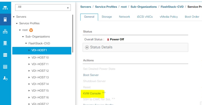
4. Click Activate Virtual Devices, mount ESXi ISO image.
5. Follow the prompts to complete installing VMware vSphere ESXi hypervisor.
6. When selecting a storage device to install ESXi, select Remote LUN provisioned through Pure Storage Administrative console and access through FC connection.
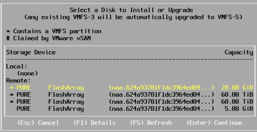
Set Up Management Networking for ESXi Hosts
Adding a management network for each VMware host is necessary for managing the host and connection to vCenter Server. Please select the IP address that can communicate with existing or new vCenter Server.
To configure the ESXi host with access to the management network, follow these steps:
1. After the server has finished rebooting, press F2 to enter into configuration wizard for ESXi Hypervisor.
2. Log in as root and enter the corresponding password.
3. Select the “Configure the Management Network” option and press Enter.
4. Select the VLAN (Optional) option and press Enter. Enter the VLAN In-Band management ID and press Enter.
5. From the Configure Management Network menu, select “IP Configuration” and press Enter.
6. Select “Set Static IP Address and Network Configuration” option by using the space bar. Enter the IP address to manage the first ESXi host. Enter the subnet mask for the first ESXi host. Enter the default gateway for the first ESXi host. Press Enter to accept the changes to the IP configuration.
7. IPv6 Configuration was set to automatic.
8. Select the DNS Configuration option and press Enter.
9. Enter the IP address of the primary and secondary DNS server. Enter Hostname
10. Enter DNS Suffixes.
11. Since the IP address is assigned manually, the DNS information must also be entered manually.
![]() The steps provided varies based on the configuration. Please make the necessary changes according to your configuration.
The steps provided varies based on the configuration. Please make the necessary changes according to your configuration.
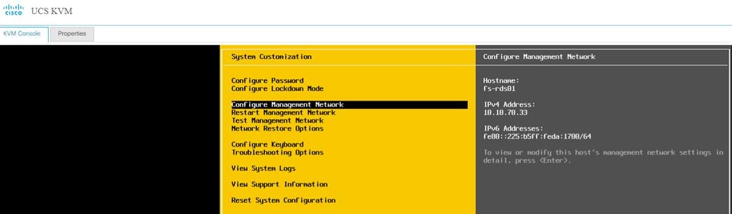
Update Cisco VIC Drivers for ESXi
When ESXi is installed from Cisco Custom ISO you might have to update Cisco VIC drivers for VMware ESXi Hypervisor to match current Cisco Hardware and Software Interoperability Matrix.
To update the Cisco VIC drivers for ESXi, follow these steps:
![]() In this Validated Design the following drivers were used:
In this Validated Design the following drivers were used:
- VMW-ESX-6.7.0-nenic-1.0.31.0
- VMW-ESX-6.7.0-nfnic-4.0.0.52
1. Log into your VMware Account to download required drivers for FNIC and NENIC as per the recommendation.
2. Enable SSH on ESXi to run following commands:
esxcli software vib update -d /path/offline-bundle.zip
VMware Clusters
The following VMware Clusters were configured in two vCenters to support the solution and testing environment:
· VCSA01
· VDI Cluster: Pure Storage FlashArray//X70 R2 with Cisco UCS
- FlashStack-Infra: Infrastructure virtual machines (vCenter, Active Directory, DNS, DHCP, SQL Server, XenDesktop Controllers, Provisioning Servers, and other common services).
- FlashStack-PVS: XenApp Hosted Shared Desktop virtual machines (Windows Server 2019 streamed with PVS) and XenDesktop Hosted Virtual Desktop virtual machines (Windows 10 64-bit non-persistent virtual desktops streamed with PVS).
- FlashStack-MCS: XenDesktop Hosted Virtual Desktop virtual machines (Windows 10 64-bit persistent virtual desktops).
· VCSA02
· VSI Launchers Cluster
- Launcher Cluster: Login VSI Cluster (The Login VSI launcher infrastructure was connected using the same set of switches but hosted on separate SAN storage and servers)
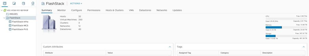
Build the Virtual Machines and Environment for Workload Testing
Software Infrastructure Configuration
This section explains how to configure the software infrastructure components that comprise this solution.
Install and configure the infrastructure virtual machines by following the process provided in Table 13 .
Table 13 Test Infrastructure Virtual Machine Configuration
| Configuration |
Citrix Virtual Apps and Desktops Controllers Virtual Machines |
Citrix Provisioning Servers Virtual Machines |
| Operating system |
Microsoft Windows Server 2019 |
Microsoft Windows Server 2016 |
| Virtual CPU amount |
6 |
6 |
| Memory amount |
24 GB |
24 GB |
| Network |
VMXNET3 Infra |
VMXNET3 VCC |
| Disk-1 (OS) size |
60 GB |
60 GB |
| Configuration |
Microsoft Active Directory DCs Virtual Machines |
vCenter Server Appliance Virtual Machine |
| Operating system |
Microsoft Windows Server 2019 |
VCSA – SUSE Linux |
| Virtual CPU amount |
4 |
16 |
| Memory amount |
8 GB |
32 GB |
| Network |
VMXNET3 Infra |
VMXNET3 Mgmt |
| Disk size |
60 GB
|
698.84 GB (across 13 VMDKs)
|
| Configuration |
Microsoft SQL Server Virtual Machine |
Citrix StoreFront Controller Virtual Machine |
| Operating system |
Microsoft Windows Server 2019 Microsoft SQL Server 2019 |
Microsoft Windows Server 2016 |
| Virtual CPU amount |
6 |
4 |
| Memory amount |
24GB |
8 GB |
| Network |
VMXNET3 Infra |
VMXNET3 Infra |
| Disk-1 (OS) size |
60 GB |
60 GB |
| Disk-2 size |
100 GB SQL Databases\Logs |
- |
Prepare the Master Targets
This section provides guidance regarding creating the golden (or master) images for the environment. Virtual machines for the master targets must first be installed with the software components needed to build the golden images. Additionally, all available patches as of February 2019 for the Microsoft operating systems, SQL server and Microsoft Office 2016 were installed.
To prepare the master virtual machines for the Hosted Virtual Desktops (HVDs) and Hosted Shared Desktops (HSDs), there are three major steps: installing the PVS Target Device x64 software, installing the Virtual Delivery Agents (VDAs), and installing application software.
![]() For this CVD, the images contain the basics needed to run the Login VSI workload.
For this CVD, the images contain the basics needed to run the Login VSI workload.
The master target Hosted Virtual Desktop (HVD) and Hosted Shared Desktop (HSD) virtual machines were configured as detailed in Table 14
Table 14 HVD and HSD Virtual Machines Configurations
| Configuration |
HVD Virtual Machines |
HSD Virtual Machines |
| Operating system |
Microsoft Windows 10 64-bit |
Microsoft Windows Server 2016 |
| Virtual CPU amount |
3 |
8 |
| Memory amount |
3 GB reserve for all guest memory |
32 GB reserve for all guest memory |
| Network |
VMXNET3 VCC |
VMXNET3 VCC |
| Citrix PVS vDisk size Full Clone Disk Size |
40 GB (dynamic) 40 GB |
60 GB (dynamic)
|
| Citrix PVS write cache Disk size |
10 GB |
10 GB |
| Citrix PVS write cache RAM cache size |
128 MB |
1024 MB |
| Additional software used for testing |
Microsoft Office 2016 Office Update applied Login VSI 4.1.39.6 Target Software (Knowledge Worker Workload) |
Microsoft Office 2016 Office Update applied Login VSI 4.1.39.6 Target Software (Knowledge Worker Workload) |
| Additional Configuration |
Configure DHCP Add to domain Install VMWare tool Install .Net 3.5 Activate Office Install VDA Agent Run PVS Imaging Wizard(For non-persistent Desktops only) |
Configure DHCP Add to domain Install VMWare tool Install .Net 3.5 Activate Office Install VDA Agent Run PVS Imaging Wizard |
Install and Configure Citrix Virtual Apps and Desktops
This section explains the installation of the core components of the Citrix Virtual Apps and Desktops 7.15 system. This CVD installs two XenDesktop Delivery Controllers to support both hosted shared desktops (HSD), non-persistent hosted virtual desktops (HVD), and persistent hosted virtual desktops (HVD).
Prerequisites
Citrix recommends that you use Secure HTTP (HTTPS) and a digital certificate to protect vSphere communications. Citrix recommends that you use a digital certificate issued by a certificate authority (CA) according to your organization's security policy. Otherwise, if the security policy allows, use the VMware-installed self-signed certificate.
To install vCenter Server self-signed Certificate, follow these steps:
1. Add the FQDN of the computer running vCenter Server to the hosts file on that server, located at SystemRoot/
WINDOWS/system32/Drivers/etc/. This step is required only if the FQDN of the computer running vCenter Server is not already present in DNS.
2. Open Internet Explorer and enter the address of the computer running vCenter Server (for example, https://FQDN as the URL).
3. Accept the security warnings.
4. Click the Certificate Error in the Security Status bar and select View certificates.
5. Click Install certificate, select Local Machine, and then click Next.
6. Select Place all certificates in the following store and then click Browse.
7. Select Show physical stores.
8. Select Trusted People.
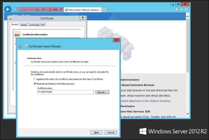
9. Click Next and then click Finish.
10. Repeat steps 1-9 on all Delivery Controllers and Provisioning Servers.
Install XenDesktop Delivery Controller, Citrix Licensing, and StoreFront
The process of installing the XenDesktop Delivery Controller also installs other key XenDesktop software components, including Studio, which is used to create and manage infrastructure components, and Director, which is used to monitor performance and troubleshoot problems.
![]() Dedicated StoreFront and License servers should be implemented for large scale deployments.
Dedicated StoreFront and License servers should be implemented for large scale deployments.
Install Citrix License Server
To install the Citrix License Server, follow these steps:
1. To begin the installation, connect to the first Citrix License server and launch the installer from the Citrix Virtual Apps and Desktops 7.15 ISO.
2. Click Start.
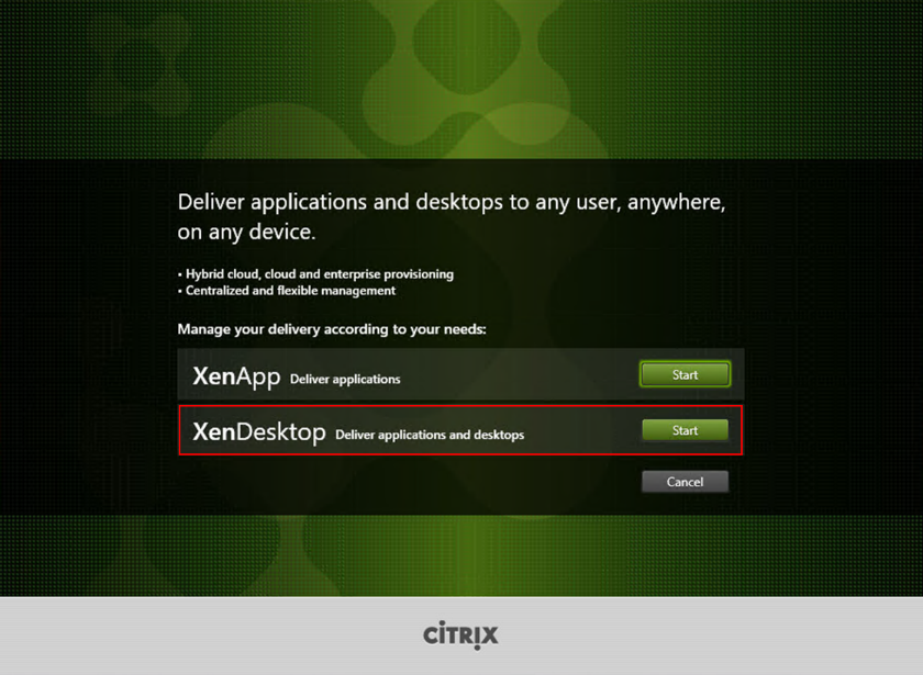
3. Click “Extend Deployment – Citrix License Server.”
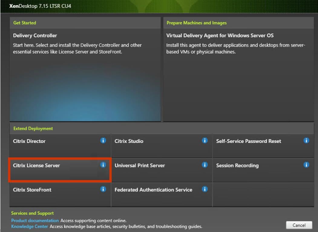
4. Read the Citrix License Agreement.
5. If acceptable, indicate your acceptance of the license by selecting the “I have read, understand, and accept the terms of the license agreement” radio button.
6. Click Next.
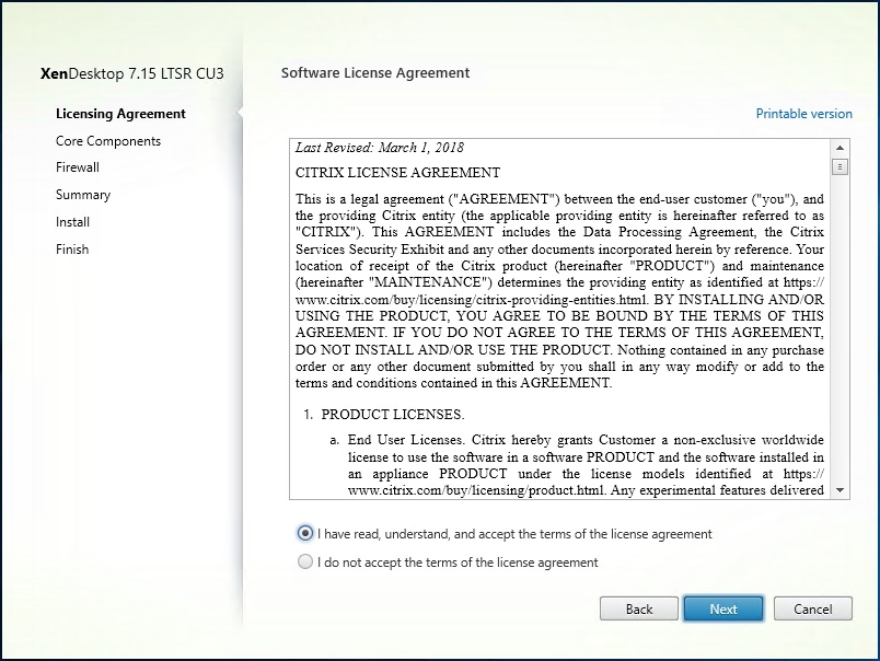
7. Click Next.
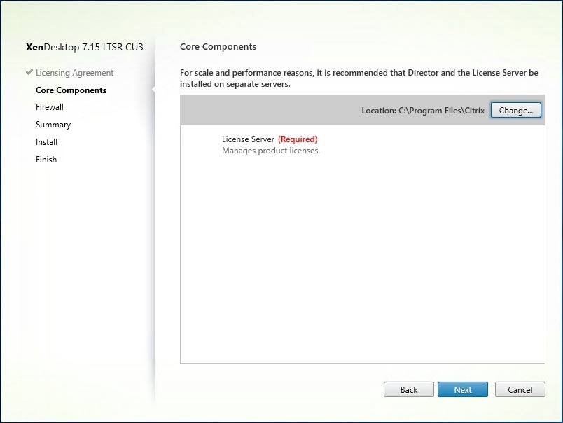
8. Select the default ports and automatically configured firewall rules.
9. Click Next.
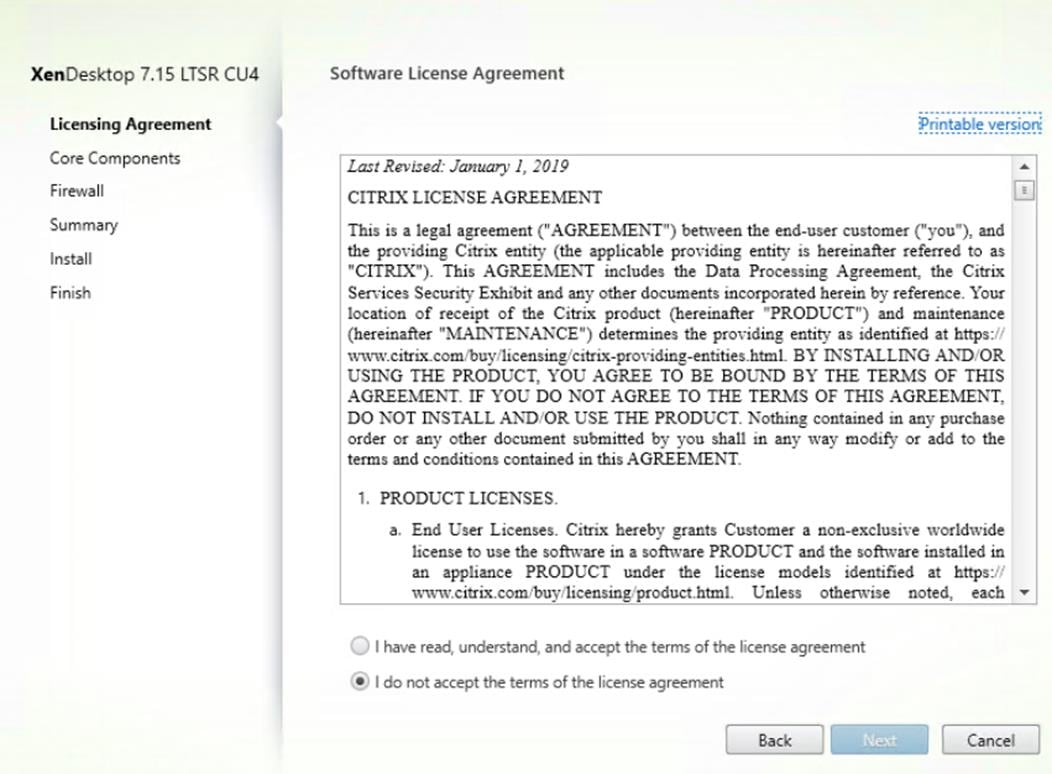
10. Click Install.
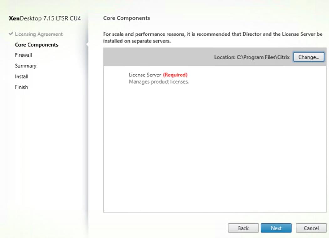
11. Click Finish to complete the installation.
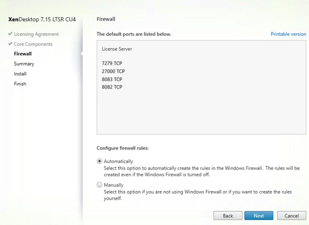
Install Citrix Licenses
To install the Citrix Licenses, follow these steps:
1. Copy the license files to the default location (C:\Program Files (x86)\Citrix\Licensing\ MyFiles) on the license server.
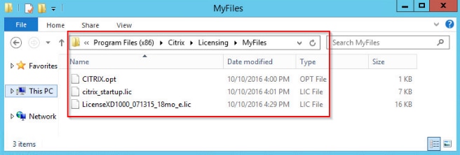
2. Restart the server or Citrix licensing services so that the licenses are activated.
3. Run the application Citrix License Administration Console.
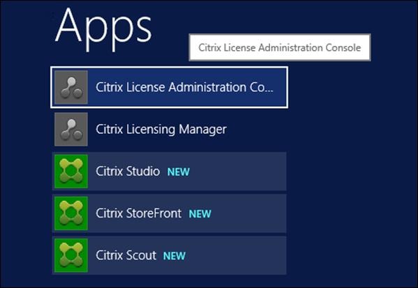
4. Confirm that the license files have been read and enabled correctly.
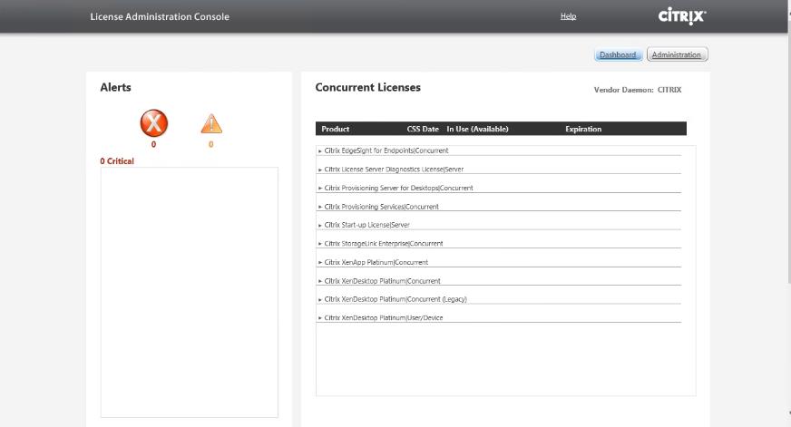
Install the XenDesktop
To begin the installation, connect to the first XenDesktop server and launch the installer from the Citrix Virtual Apps and Desktops 7_15_4000 ISO, and follow these steps:
1. Click Start.
The installation wizard presents a menu with three subsections.
2. Click “Get Started - Delivery Controller.”
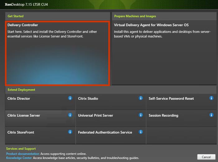
3. Read the Citrix License Agreement.
4. If acceptable, indicate your acceptance of the license by selecting the “I have read, understand, and accept the terms of the license agreement” radio button.
5. Click Next.
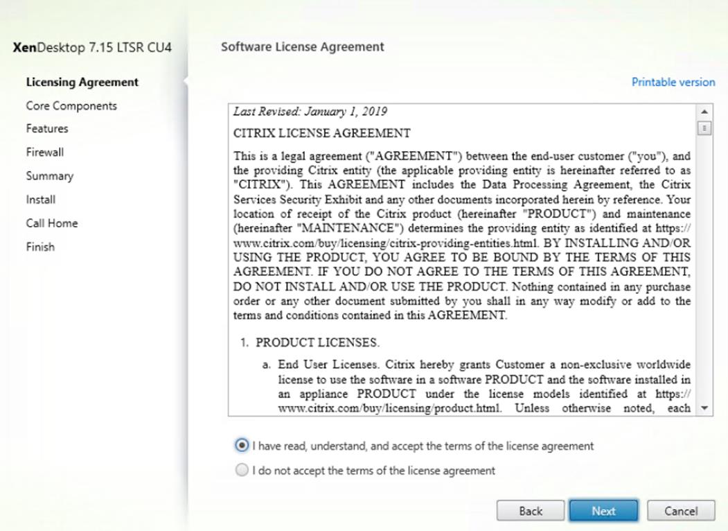
6. Select the components to be installed on the first Delivery Controller Server:
- Delivery Controller
- Studio
- Director
7. Click Next.
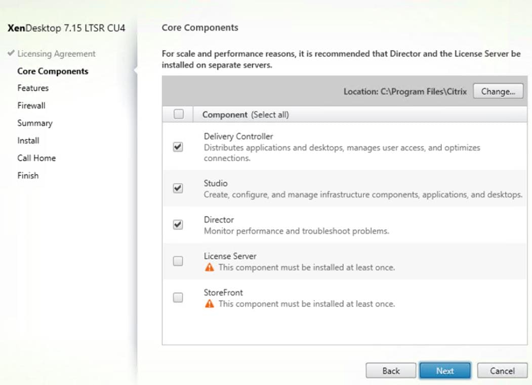
8. Since a dedicated SQL Server will be used to Store the Database, leave “Install Microsoft SQL Server 2014 SP2 Express” unchecked.
9. Click Next.
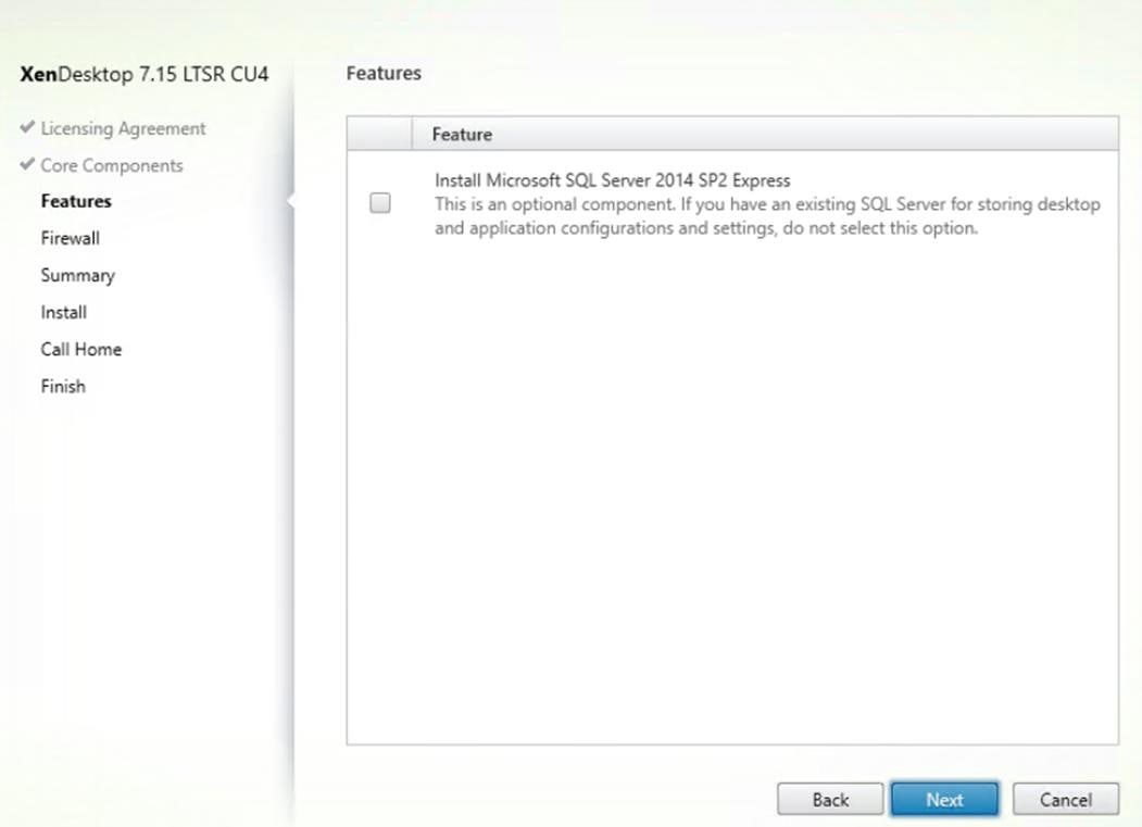
10. Select the default ports and automatically configured firewall rules.
11. Click Next.
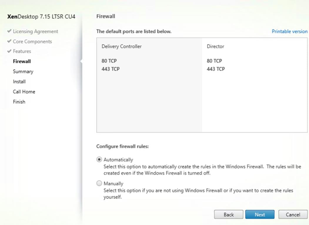
12. Click Install to begin the installation.
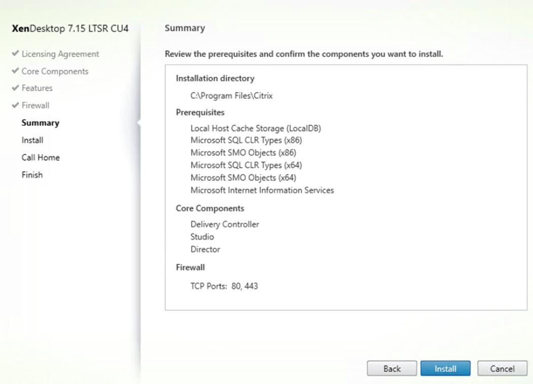
13. (Optional) Configure Smart Tools/Call Home participation.
14. Click Next.
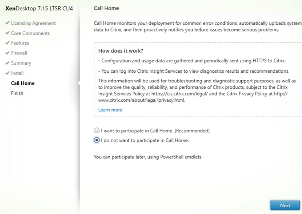
15. Click Finish to complete the installation.
16. (Optional) Check Launch Studio to launch Citrix Studio Console.
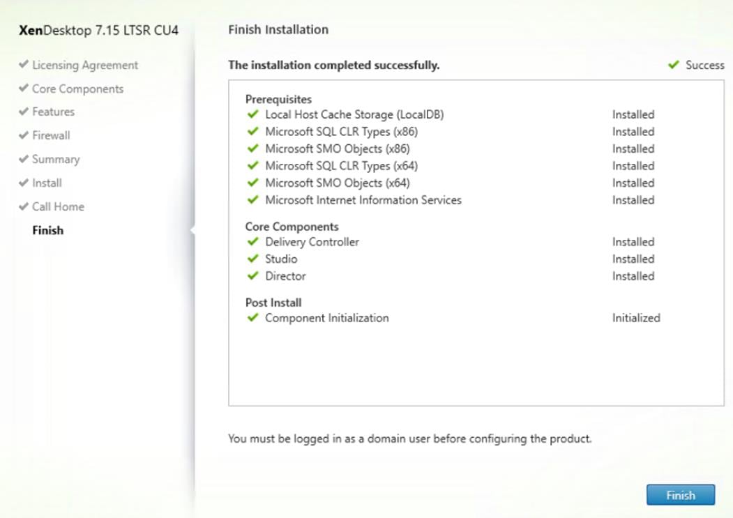
Additional XenDesktop Controller Configuration
After the first controller is completely configured and the Site is operational, you can add additional controllers. In this CVD, we created two Delivery Controllers.
To configure additional XenDesktop controllers, follow these steps:
1. To begin the installation of the second Delivery Controller, connect to the second XenDesktop server and launch the installer from the Citrix Virtual Apps and Desktops 7.15_4000 ISO.
2. Click Start.
3. Click Delivery Controller.
4. Repeat the same steps used to install the first Delivery Controller, including the step of importing an SSL certificate for HTTPS between the controller and vSphere.
5. Review the Summary configuration.
6. Click Install.
7. (Optional) Configure Smart Tools/Call Home participation.
8. Click Next.
9. Verify the components installed successfully.
10. Click Finish.
Configure the XenDesktop Site
Citrix Studio is a management console that allows you to create and manage infrastructure and resources to deliver desktops and applications. Replacing Desktop Studio from earlier releases, it provides wizards to set up your environment, create workloads to host applications and desktops, and assign applications and desktops to users.
Citrix Studio launches automatically after the XenDesktop Delivery Controller installation, or if necessary, it can be launched manually. Studio is used to create a Site, which is the core Citrix Virtual Apps and Desktops 7.15environment consisting of the Delivery Controller and the Database.
To configure XenDesktop, follow these steps:
1. From Citrix Studio, click Deliver applications and desktops to your users.
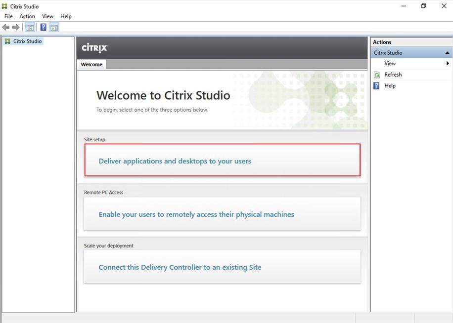
2. Select the “An empty, unconfigured Site” radio button.
3. Enter a site name.
4. Click Next.

5. Provide the Database Server Locations for each data type and click Next.
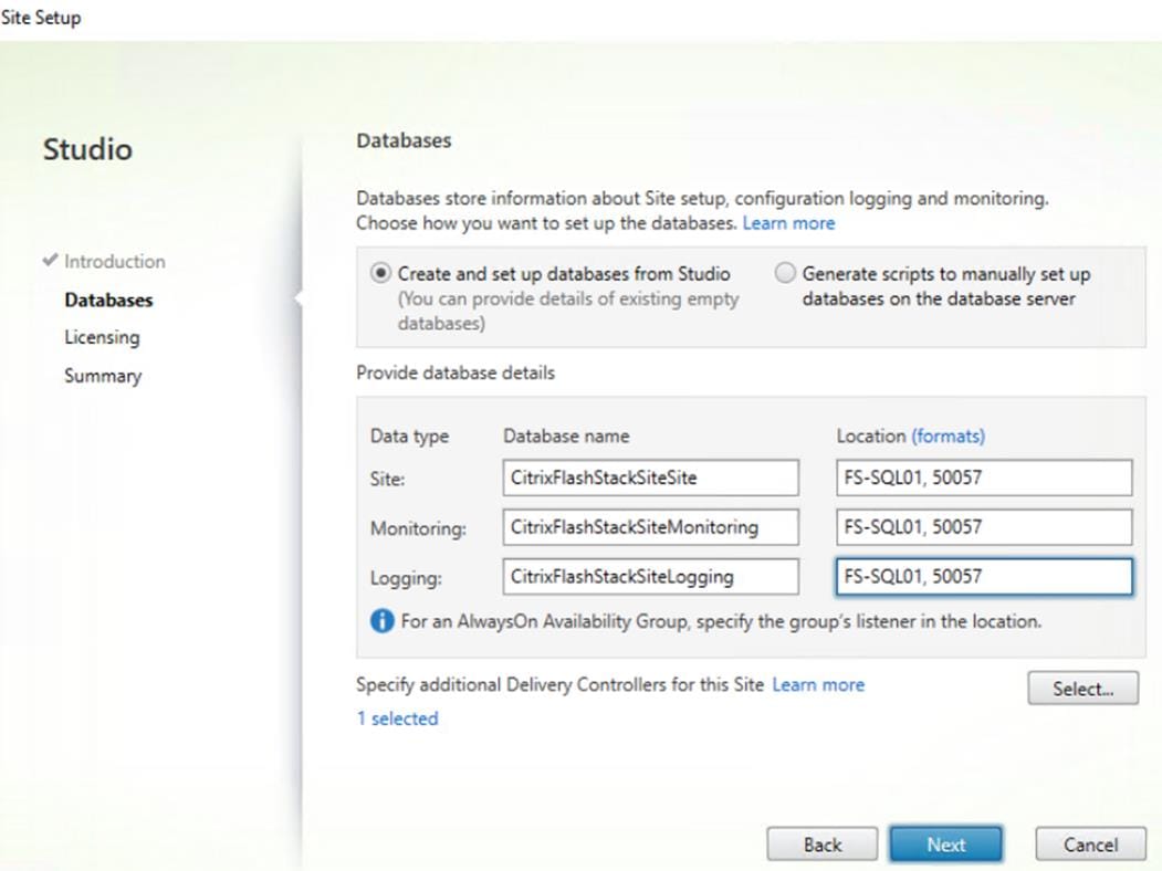
![]() For an AlwaysOn Availability Group, use the group’s listener DNS name.
For an AlwaysOn Availability Group, use the group’s listener DNS name.
6. Click Select to specify additional controllers (Optional at this time. Additional controllers can be added later).
7. Click Next.
8. Provide the FQDN of the license server.
9. Click Connect to validate and retrieve any licenses from the server.
![]() If no licenses are available, you can use the 30-day free trial or activate a license file.
If no licenses are available, you can use the 30-day free trial or activate a license file.
10. Select the appropriate product edition using the license radio button.
11. Click Next.
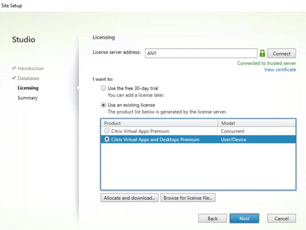
12. Verify information on the Summary page.
13. Click Finish.
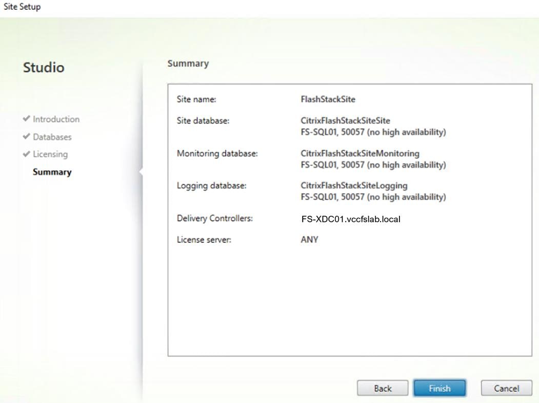
Configure the XenDesktop Site Hosting Connection
To configure the XenDesktop site hosting connection, follow these steps:
1. From Configuration > Hosting in Studio, click Add Connection and Resources in the right pane.
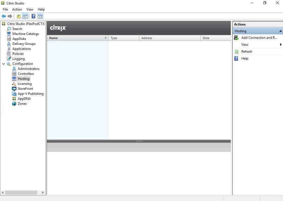
2. Select the Connection type of VMware vSphere.
3. Enter the FQDN of the vCenter server (in Server_FQDN/sdk format).
4. Enter the username (in domain\username format) for the vSphere account.
5. Provide the password for the vSphere account.
6. Provide a connection name.
7. Check Studio Tools radio button required to support desktop provisioning task by this connection.
8. Click Next.
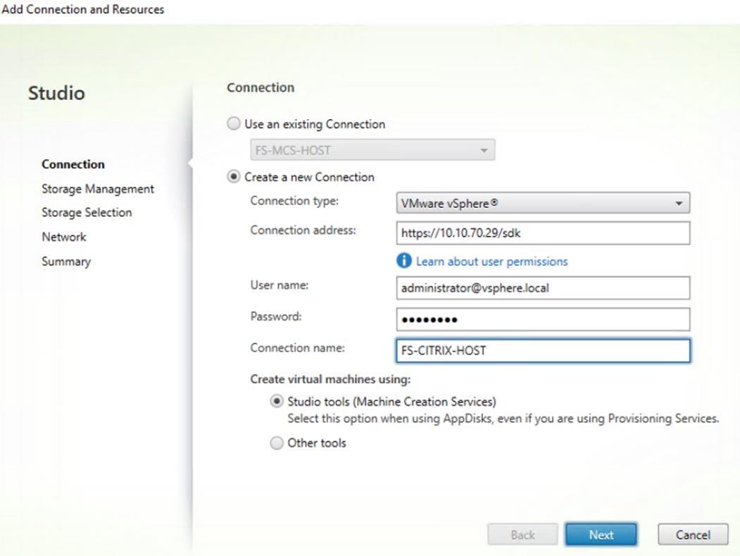
9. Accept the certificate and click OK to trust the hypervisor connection.
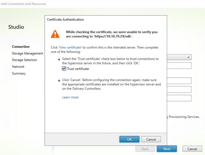
10. Select Cluster that will be used by this connection.
11. Check Use storage shared by hypervisors radio button.
12. Click Next.
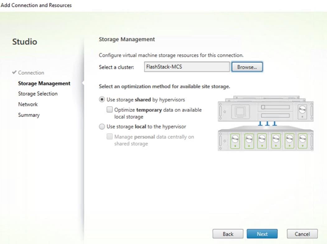
13. Make Storage selection to be used by this connection, use all provisioned for desktops datastores.
14. Click Next.
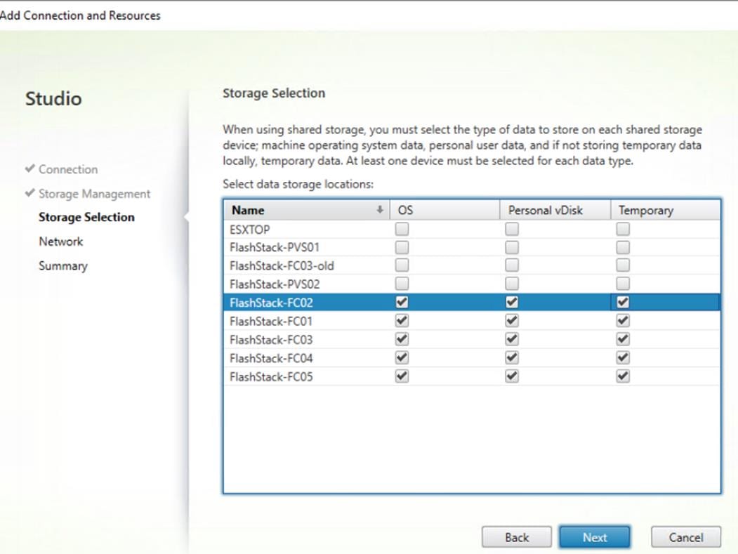
15. Make Network selection to be used by this connection.
16. Click Next.

17. Review Site configuration Summary and click Finish.
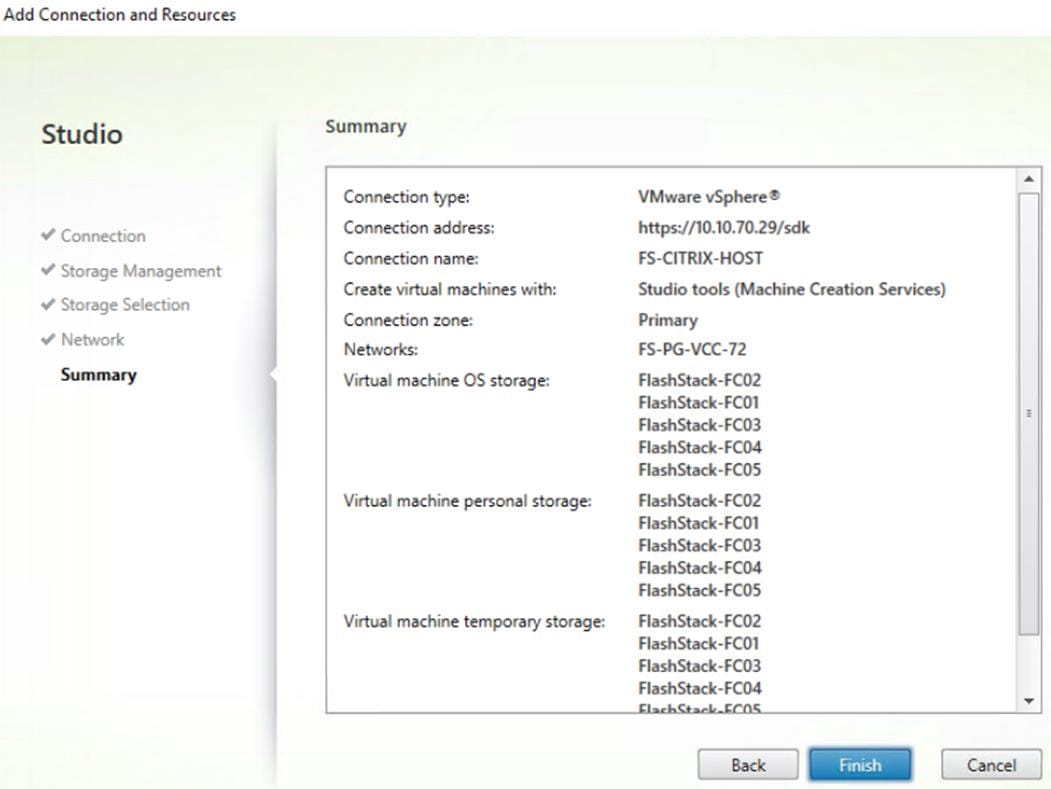
Add Resources to the Site Hosting Connection
To add resources to the additional vCenter clusters, follow these steps:
1. From Configuration > Hosting in Studio click Add Connection and Resources.
2. Select Use an existing Connection, use connection previously created for FlashStack environment.
3. Click Next.
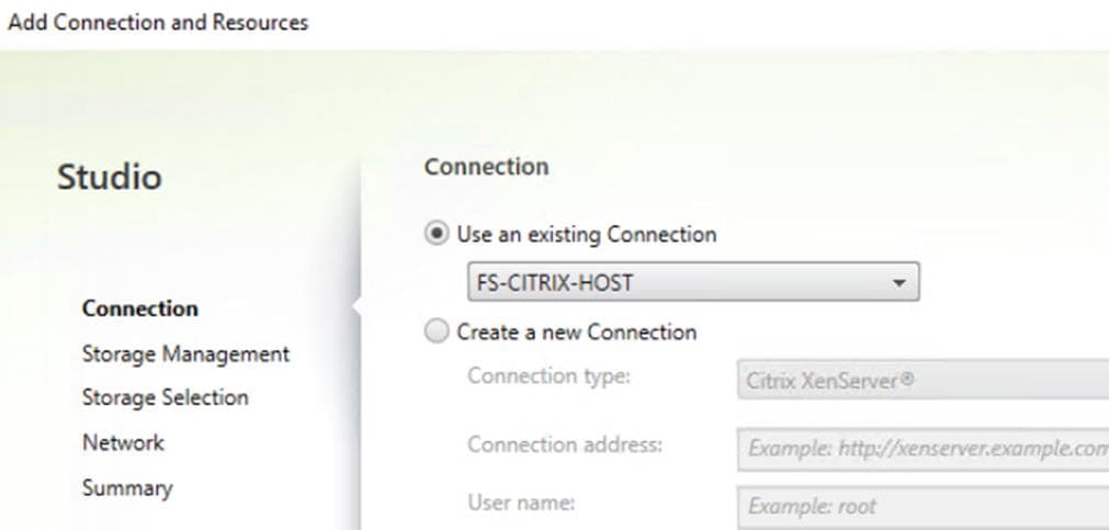
4. Select Cluster you adding to this connection.
5. Check Use storage shared by hypervisors radio button.
6. Click Next.
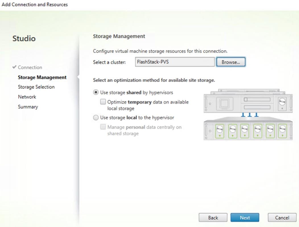
7. Select the Storage selection to be used by this connection, use all provisioned for desktops FC datastores.
8. Click Next.

9. Select the Network selection to be used by this connection.
10. Click Next.
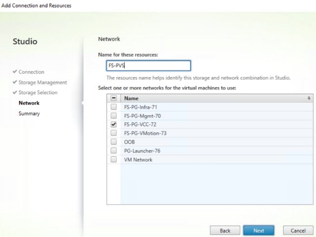
11. Review the Site configuration Summary and click Finish.
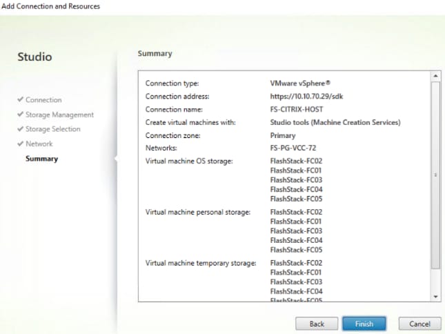
12. Repeat steps 1-11 to add all additional clusters.
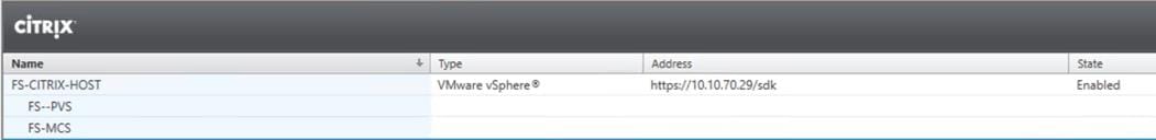
Configure the XenDesktop Site Administrators
To configure the XenDesktop site administrators, follow these steps:
1. Connect to the XenDesktop server and open Citrix Studio Management console.
2. From the Configuration menu, right-click Administrator and select Create Administrator from the drop-down list.
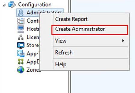
3. Select/Create appropriate scope and click Next.
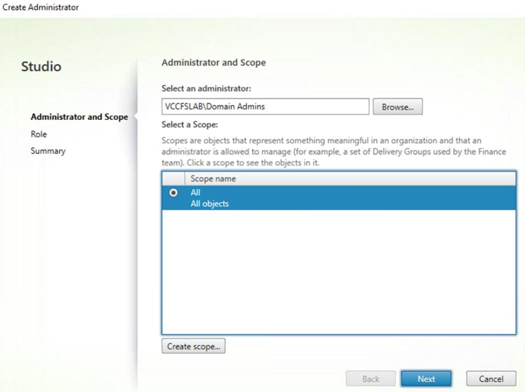
4. Select an appropriate Role.
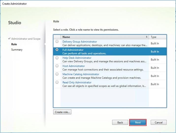
5. Review the Summary, check Enable administrator and click Finish.
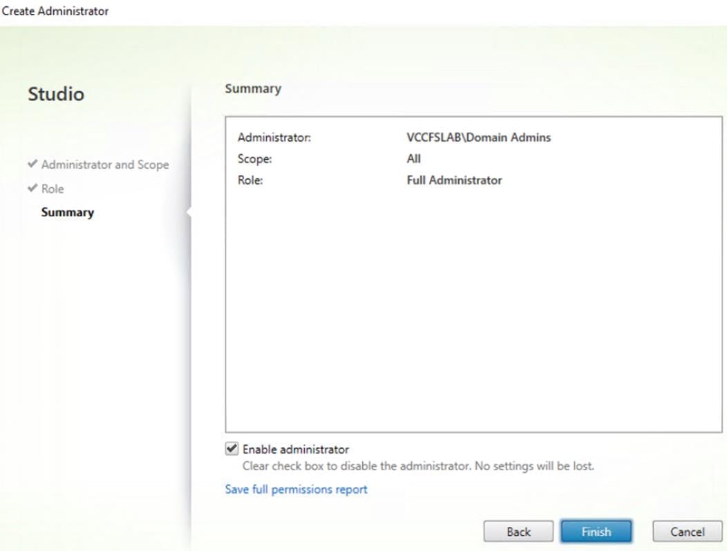
Install and Configure StoreFront
Citrix StoreFront stores aggregate desktops and applications from XenDesktop sites, making resources readily available to users. In this CVD, we created two StoreFront servers on dedicated virtual machines.
To install and configure StoreFront, follow these steps:
1. To begin the installation of the StoreFront, connect to the first StoreFront server and launch the installer from the Citrix Virtual Apps and Desktops 7.15.4000 ISO.
2. Click Start.
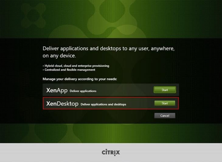
3. Click Extend Deployment Citrix StoreFront.
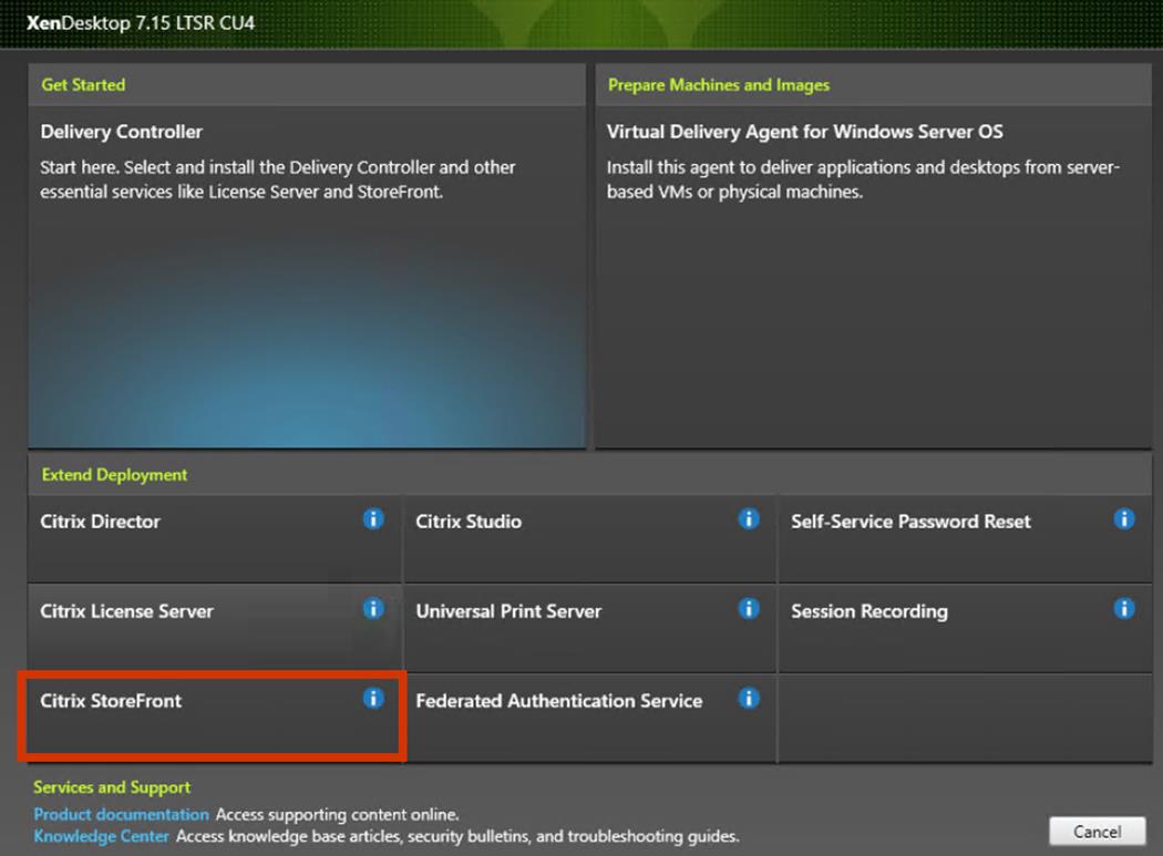
4. If acceptable, indicate your acceptance of the license by selecting the “I have read, understand, and accept the terms of the license agreement” radio button.
5. Click Next.
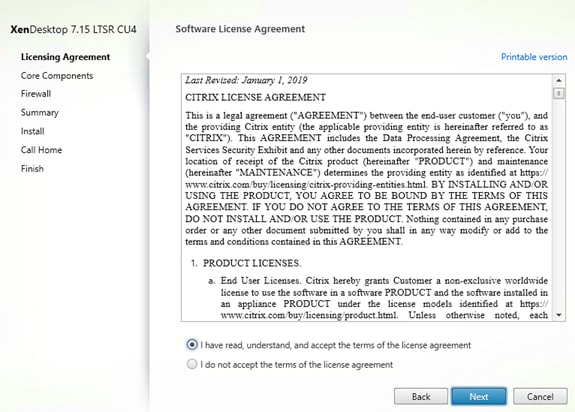
6. Click Next.
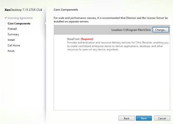
7. Select the default ports and automatically configured firewall rules.
8. Click Next.
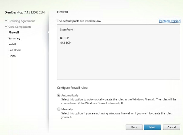
9. Click Install.
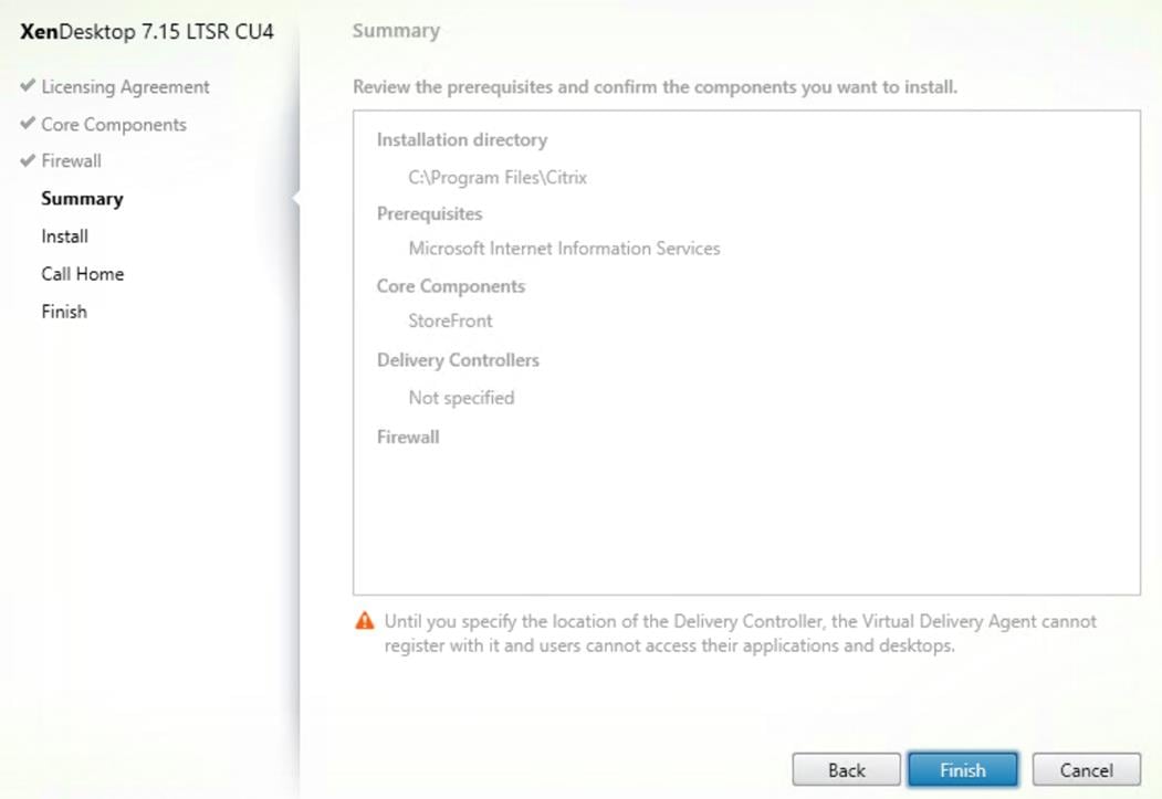
10. (Optional) Click “I want to participate in Call Home.”
11. Click Next.
12. Check “Open the StoreFront Management Console.”
13. Click Finish.
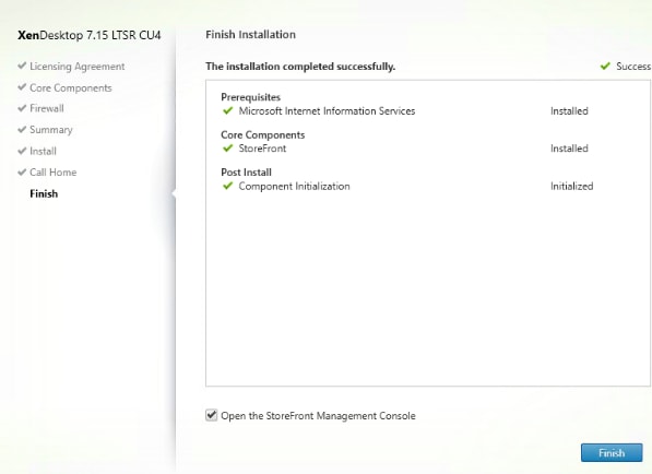
14. Click Create a new deployment.
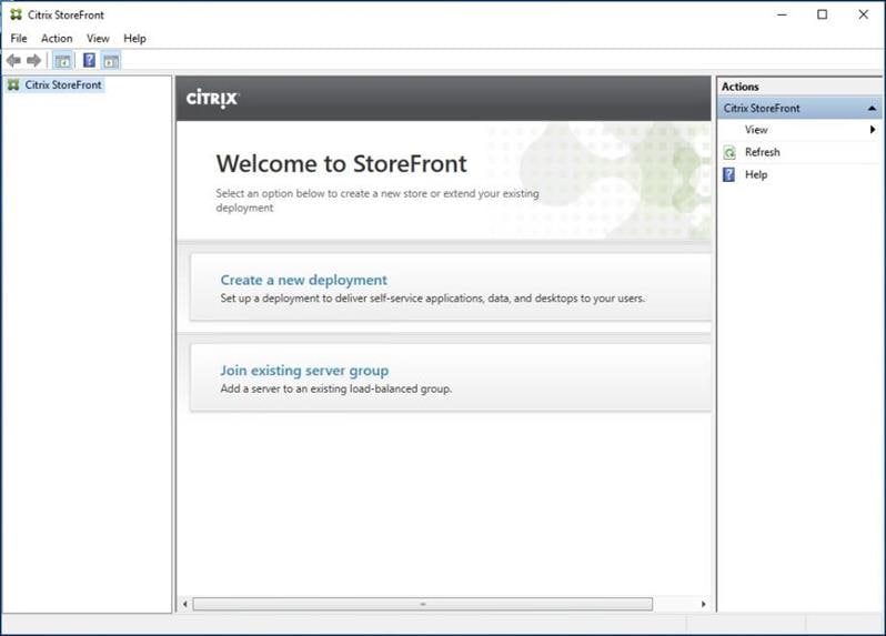
15. Click Next.
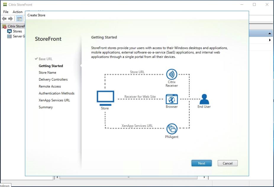
![]() For a multiple server deployment use the load balancing environment in the Base URL box.
For a multiple server deployment use the load balancing environment in the Base URL box.
16. Specify a name for your store.
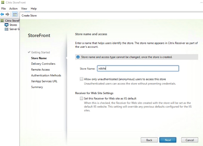
17. Click Next.
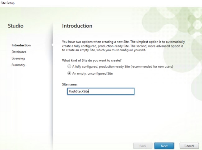
18. Add the required Delivery Controllers to the store.
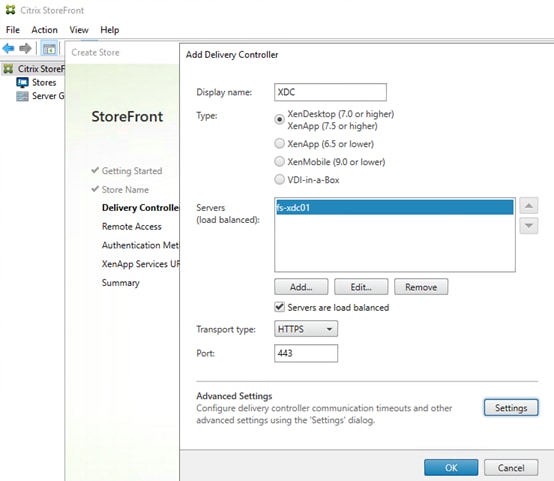
19. Click Next.
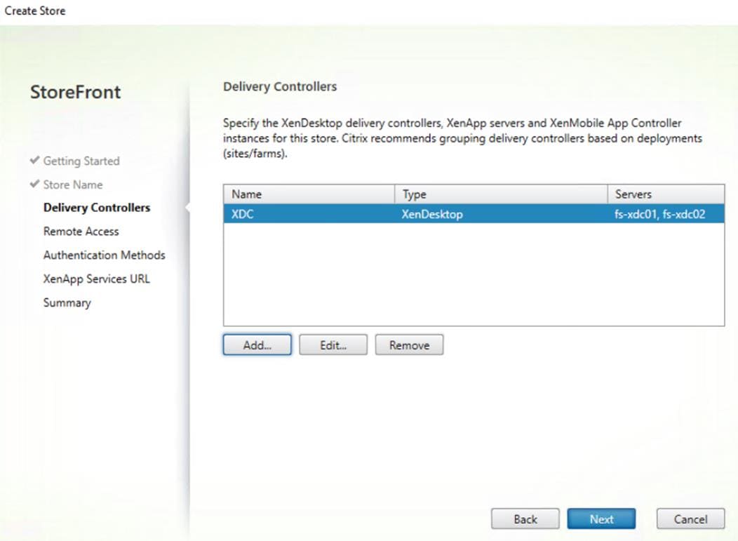
20. Specify how connecting users can access the resources, in this environment only local users on the internal network are able to access the store.
21. Click Next.
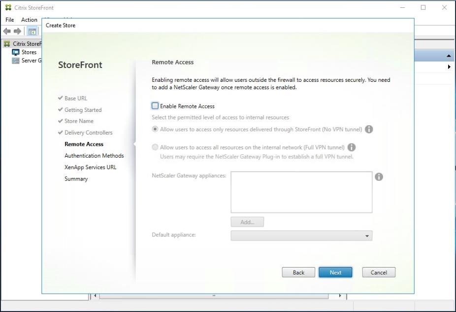
22. On the ”Authentication Methods” page, select the methods your users will use to authenticate to the store. The following methods were configured in this deployment:
- Username and password: Users enter their credentials and are authenticated when they access their stores.
- Domain passthrough: Users authenticate to their domain-joined Windows computers and their credentials are used to log them on automatically when they access their stores.
23. Click Next.
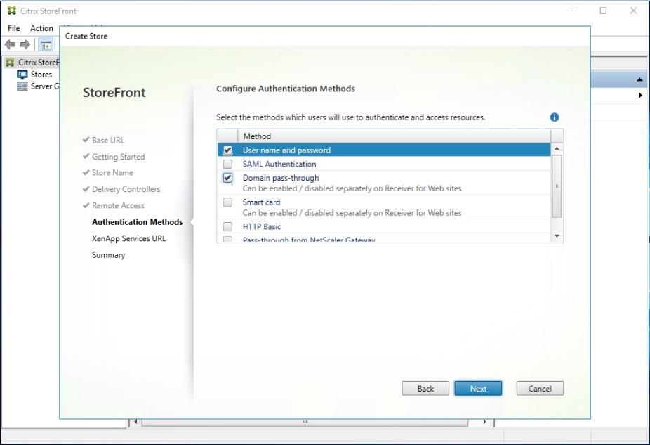
24. Configure the XenApp Service URL for users who use PNAgent to access the applications and desktops.
25. Click Create.
. 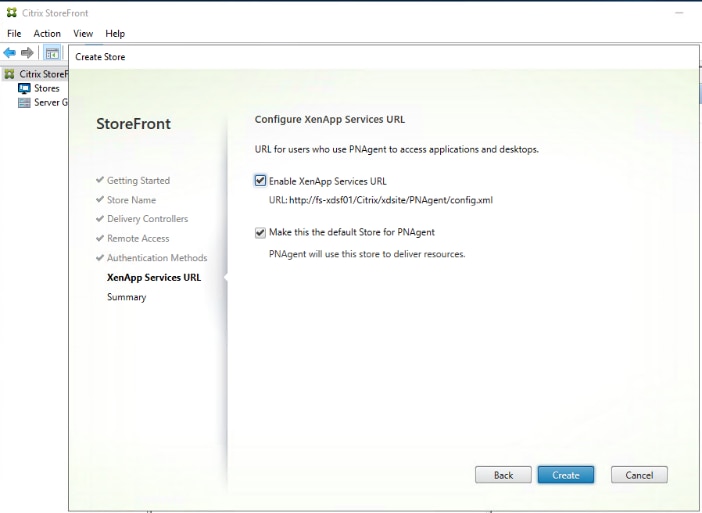
26. After creating the store click Finish.
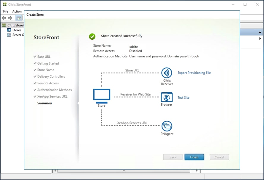
Additional StoreFront Configuration
After the first StoreFront server is completely configured and the Store is operational, you can add additional servers.
To configure additional StoreFront server, follow these steps:
1. To install the second StoreFront, use the same installation steps outlined above.
2. On the first StoreFront controller select Add Server from the Actions pane Select Server Group from the menu.
3. Connect to the first StoreFront server
4. To add the second server and generate the authorization information that allows the additional StoreFront server to join the server group, select Add Server from Actions pane in the Server Group.
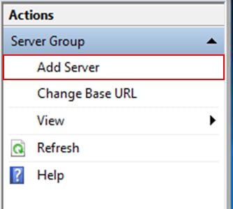
5. Copy the authorization code
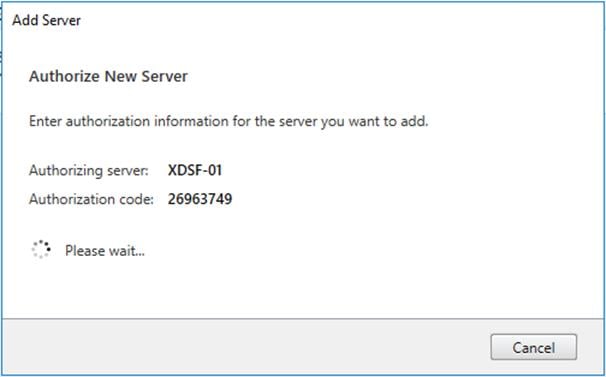
6. From the StoreFront Console on the second server select “Join existing server group.”
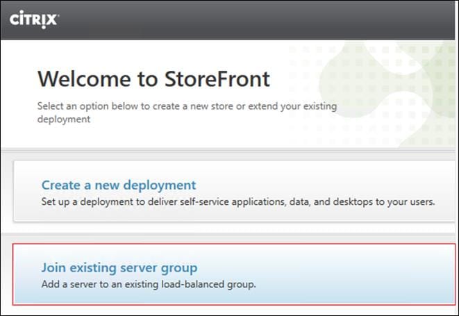
7. In the Join Server Group dialog, enter the name of the first Storefront server and paste the Authorization code into the Join Server Group dialog.
8. Click Join.
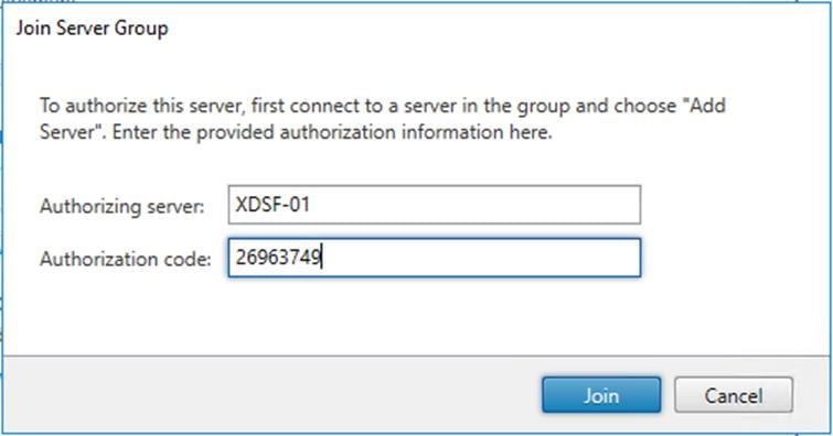
9. A message appears when the second server has joined successfully.
10. Click OK.
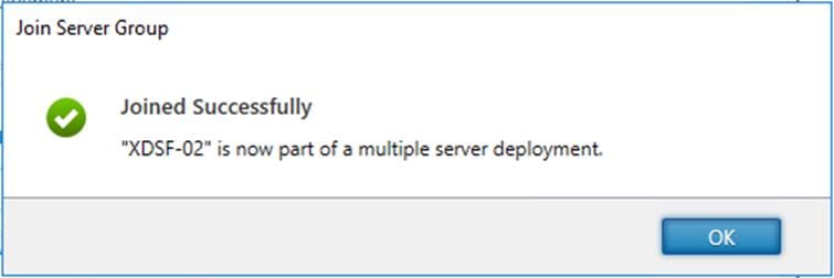
The second StoreFront is now in the Server Group.
Install and Configure Citrix Provisioning Server 7.15 CU4
In most implementations, there is a single vDisk providing the standard image for multiple target devices. Thousands of target devices can use a single vDisk shared across multiple Provisioning Services (PVS) servers in the same farm, simplifying virtual desktop management. This section describes the installation and configuration tasks required to create a PVS implementation.
The PVS server can have many stored vDisks, and each vDisk can be several gigabytes in size. Your streaming performance and manageability can be improved using a RAID array, SAN, or NAS. PVS software and hardware requirements are available in the Provisioning Services 7.15 document.
Prerequisites
Set the following Scope Options on the DHCP server hosting the PVS target machines (for example, VDI, RDS).
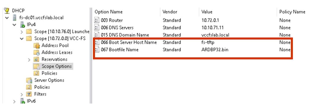
![]() The boot server IP was configured for Load Balancing by NetScaler VPX to support high availability of the TFTP service.
The boot server IP was configured for Load Balancing by NetScaler VPX to support high availability of the TFTP service.
To Configure TFTP Load Balancing, follow these steps:
1. Create a DNS host records with multiple PVS Servers IP for TFTP Load Balancing.
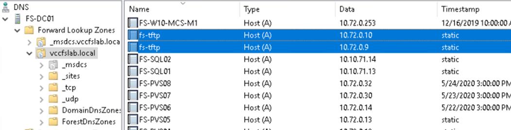
A Citrix best practice cited in this CTX article, apply the following registry setting both the PVS servers and target machines:
HKEY_LOCAL_MACHINE\SYSTEM\CurrentControlSet\Services\TCPIP\Parameters\
Key: "DisableTaskOffload" (dword)
Value: "1"
Only one MS SQL database is associated with a farm. You can choose to install the Provisioning Services database software on an existing SQL database, if that machine can communicate with all Provisioning Servers within the farm, or with a new SQL Express database machine, created using the SQL Express software that is free from Microsoft.
The following databases are supported: Microsoft SQL Server 2008 SP3 through 2016 (x86, x64, and Express editions). Please check Citrix documentation for further reference.
Microsoft SQL 2019 was installed separately for this CVD.
To install and configure Citrix Provisioning Service 7.15, follow these steps:
1. Insert the Citrix Provisioning Services 7.15.15 ISO and let AutoRun launch the installer.
2. Click the Console Installation button.
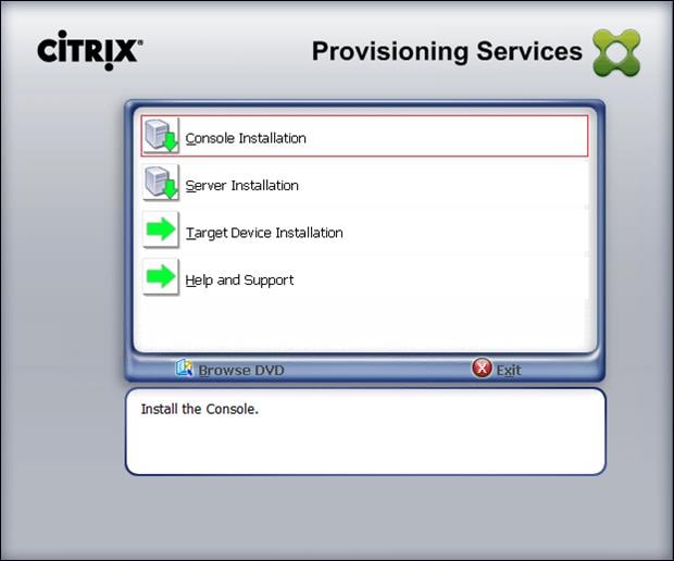
3. Click Next to start the console installation.
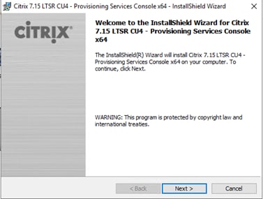
4. Read the Citrix License Agreement.
5. If acceptable, select the radio button labeled “I accept the terms in the license agreement.”
6. Click Next.
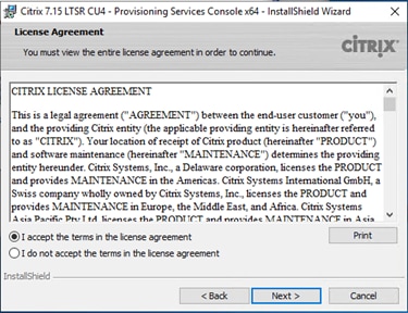
7. Optionally provide User Name and Organization.
8. Click Next.
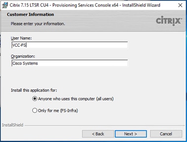
9. Accept the default path.
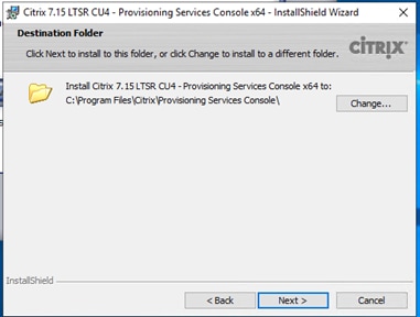
10. Click Next.
11. Click Finish after successful installation.
12. From the main installation screen, select Server Installation.
13. The installation wizard will check to resolve dependencies and then begin the PVS server installation process.
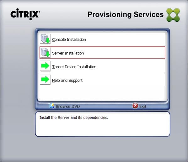
14. Click Install on the prerequisites dialog.
15. Click Yes when prompted to install the SQL Native Client.
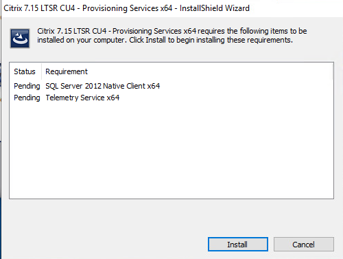
16. Click Next when the Installation wizard starts.
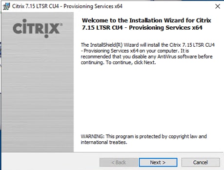
17. Review the license agreement terms.
18. If acceptable, select the radio button labeled “I accept the terms in the license agreement.”
19. Click Next.
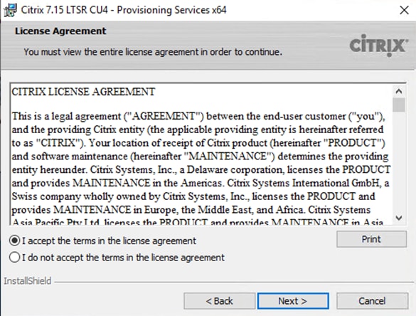
20. Provide User Name and Organization information. Select who will see the application.
21. Click Next.
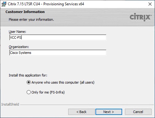
22. Accept the default installation location.
23. Click Next.
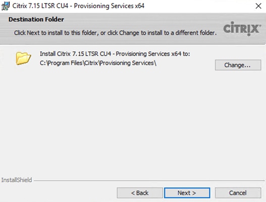
24. Click Install to begin the installation.
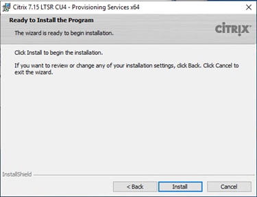
25. Click Finish when the install is complete.
The PVS Configuration Wizard starts automatically.
26. Click Next.
27. Since the PVS server is not the DHCP server for the environment, select the radio button labeled, “The service that runs on another computer.”
28. Click Next.
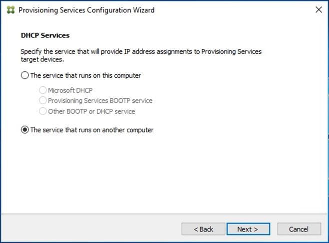
29. Since DHCP boot options 66 and 67 are used for TFTP services, select the radio button labeled, “The service that runs on another computer.”
30. Click Next.
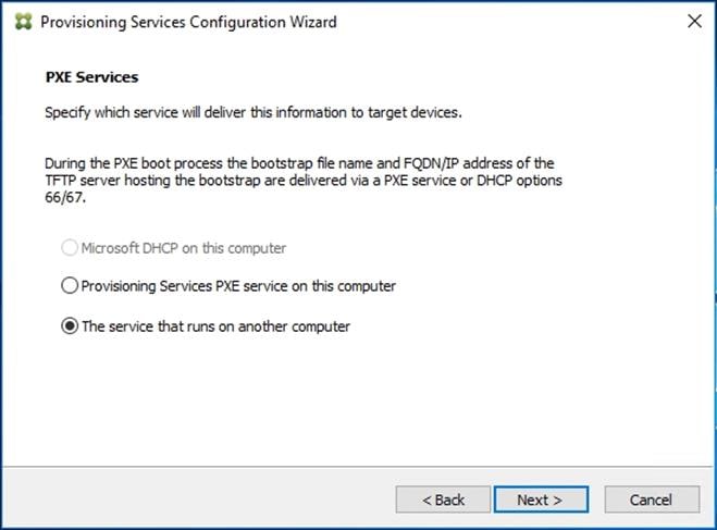
31. Since this is the first server in the farm, select the radio button labeled, “Create farm.”
32. Click Next.
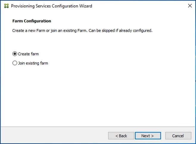
33. Enter the FQDN of the SQL server.
34. Click Next.
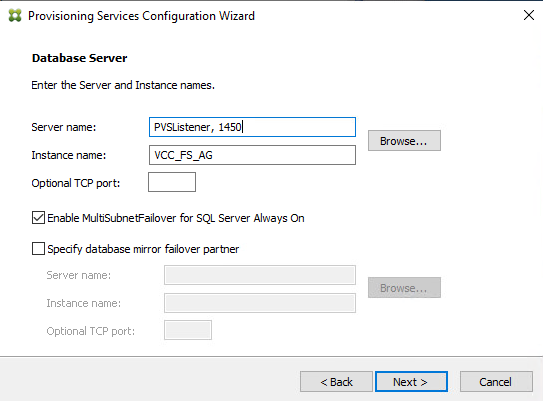
35. Provide the Database, Farm, Site, and Collection name.
36. Click Next.
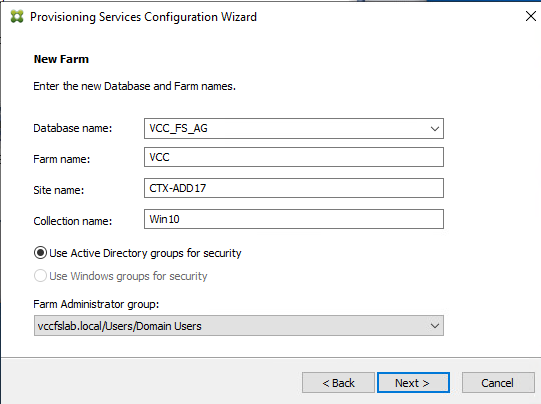
37. Provide the vDisk Store details.
38. Click Next.
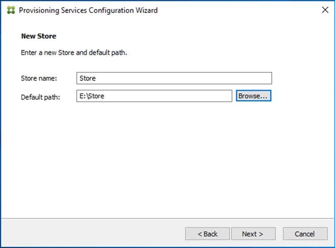
![]() For large scale PVS environment, it is recommended to create the share using support for CIFS/SMB3 on an enterprise ready File Server.
For large scale PVS environment, it is recommended to create the share using support for CIFS/SMB3 on an enterprise ready File Server.
39. Provide the FQDN of the license server.
40. Optionally, provide a port number if changed on the license server.
41. Click Next.
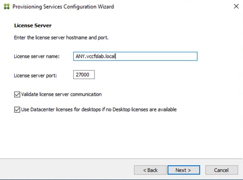
![]() If an Active Directory service account is not already setup for the PVS servers, create that account prior to clicking Next on this dialog.
If an Active Directory service account is not already setup for the PVS servers, create that account prior to clicking Next on this dialog.
42. Select the Specified user account radio button.
43. Complete the User name, Domain, Password, and Confirm password fields, using the PVS account information created earlier.
44. Click Next.
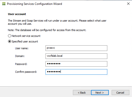
45. Set the Days between password updates to 7.
![]() This will vary per environment. “7 days” for the configuration was appropriate for testing purposes.
This will vary per environment. “7 days” for the configuration was appropriate for testing purposes.
46. Click Next.
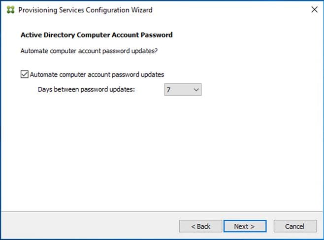
47. Keep the defaults for the network cards.
48. Click Next.
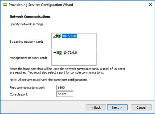
49. Select Use the Provisioning Services TFTP service checkbox.
50. Click Next.
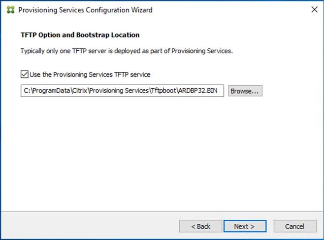
51. Make sure that the IP Addresses for all PVS servers are listed in the Stream Servers Boot List.
52. Click Next.
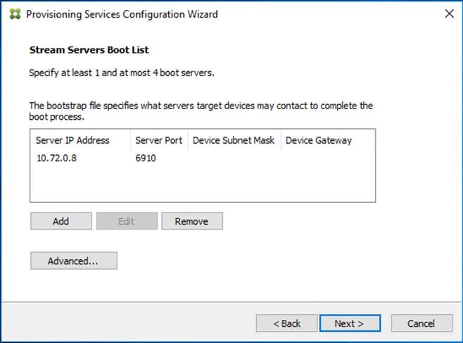
53. If Soap Server is used, provide details.
54. Click Next.
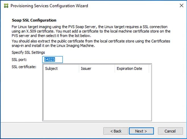
55. If desired fill in Problem Report Configuration.
56. Click Next.
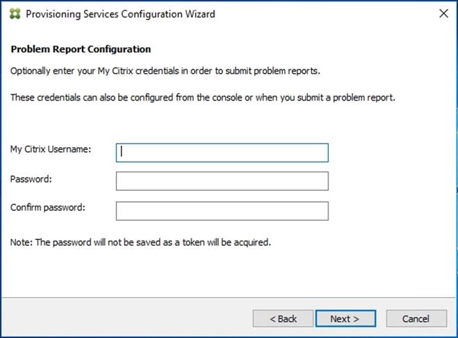
57. Click Finish to start the installation.
58. When the installation is completed, click Done.
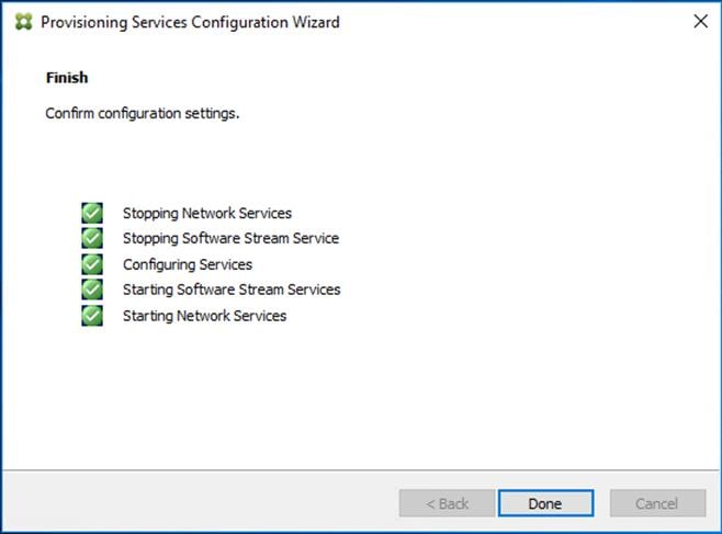
Install Additional PVS Servers
Complete the installation steps on the additional PVS servers up to the configuration step where it asks to Create or Join a farm. In this CVD, we repeated the procedure to add a total of three PVS servers. To install additional PVS servers, follow these steps:
1. On the Farm Configuration dialog, select “Join existing farm.”
2. Click Next.
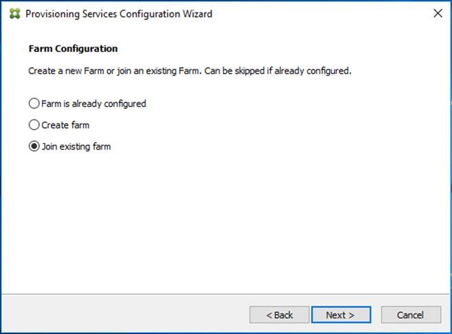
3. Provide the FQDN of the SQL Server.
4. Click Next.
5. Accept the Farm Name.
6. Click Next.
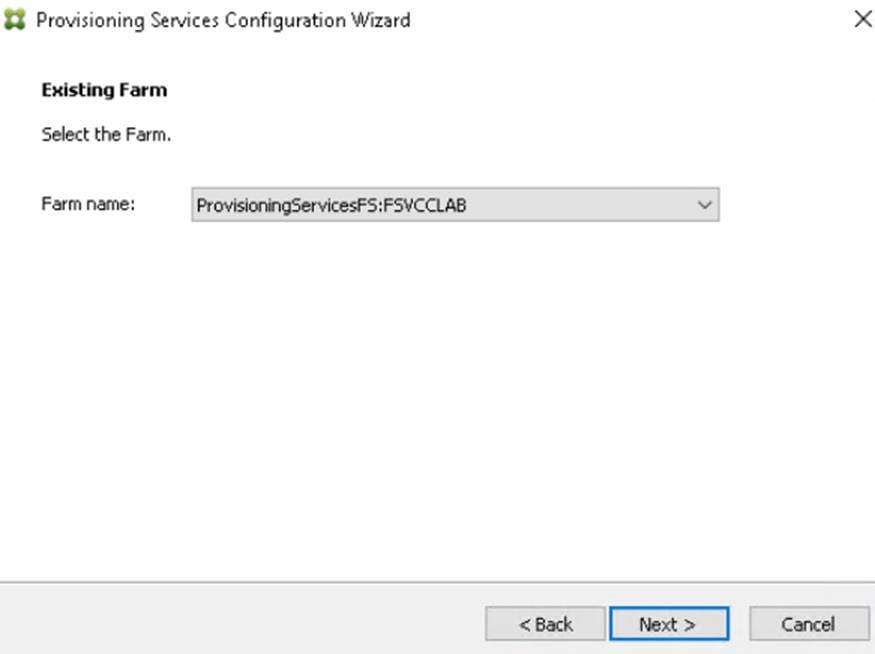
7. Accept the Existing Site.
8. Click Next.
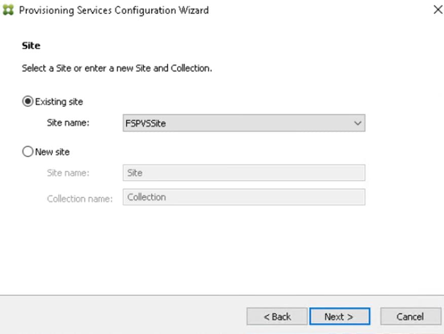
9. Accept the existing vDisk store.
10. Click Next.
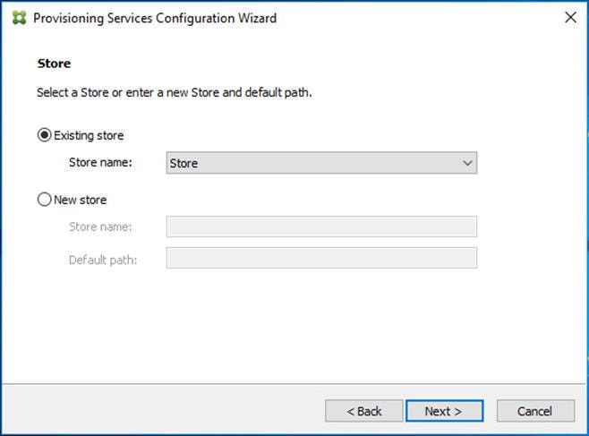
11. Provide the FQDN of the license server.
12. Optionally, provide a port number if changed on the license server.
13. Click Next.
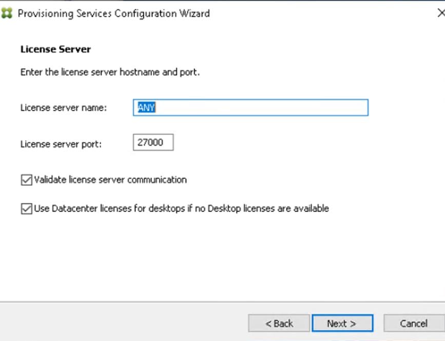
14. Provide the PVS service account information.
15. Click Next.
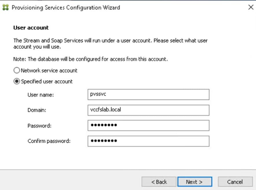
16. Set the Days between password updates to 7.
17. Click Next.
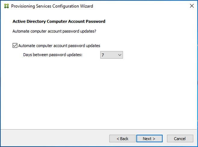
18. Accept the network card settings.
19. Click Next.
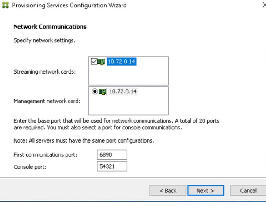
20. Select Use the Provisioning Services TFTP service checkbox.
21. Click Next.
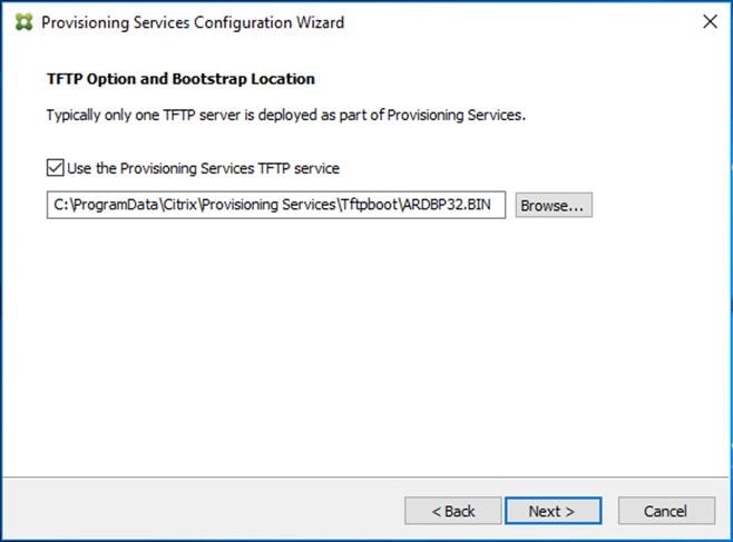
22. Make sure that the IP Addresses for all PVS servers are listed in the Stream Servers Boot List.
23. Click Next.
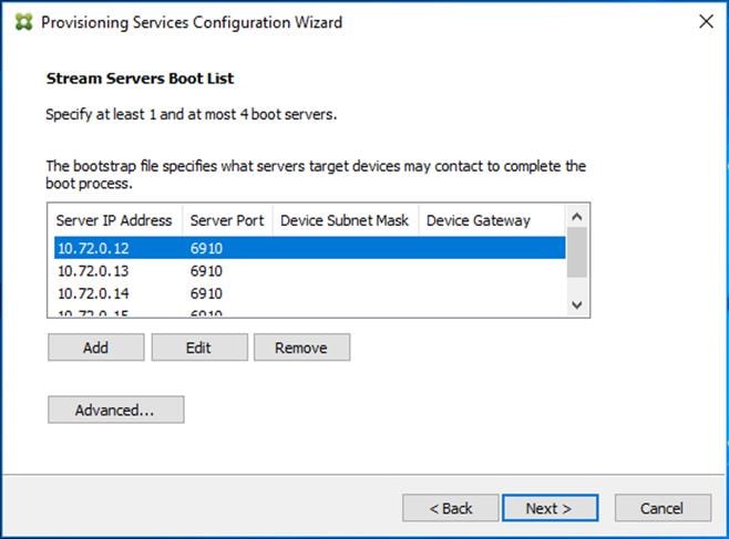
24. If Soap Server is used, provide details.
25. Click Next.
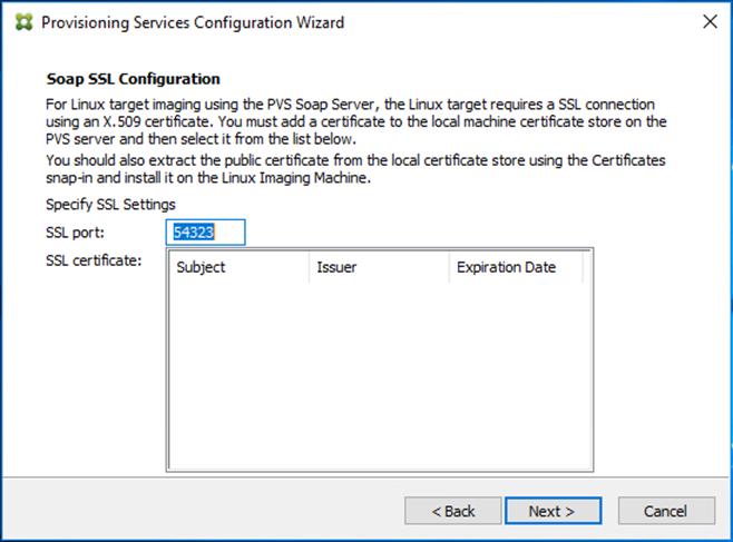
26. If desired fill in Problem Report Configuration.
27. Click Next.
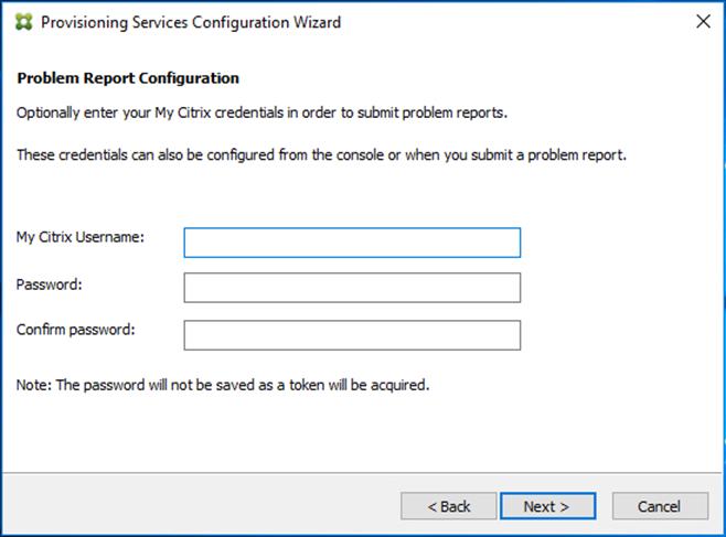
28. Click Finish to start the installation process.
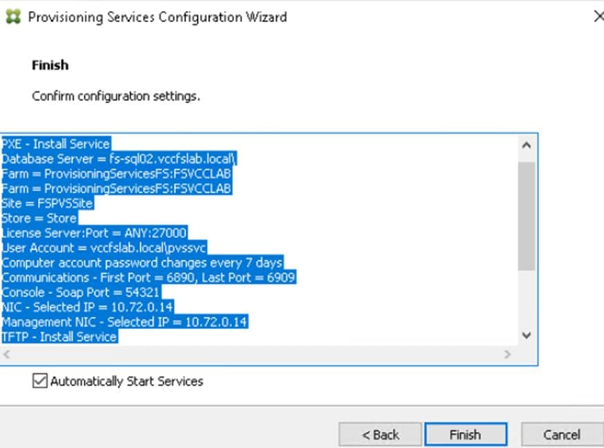
29. Click Done when the installation finishes.
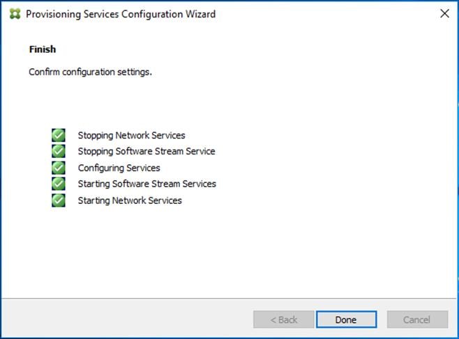
![]() You can optionally install the Provisioning Services console on the second PVS server following the procedure in the section Installing Provisioning Services.
You can optionally install the Provisioning Services console on the second PVS server following the procedure in the section Installing Provisioning Services.
![]() After completing the steps to install the three additional PVS servers, launch the Provisioning Services Console to verify that the PVS Servers and Stores are configured and that DHCP boot options are defined.
After completing the steps to install the three additional PVS servers, launch the Provisioning Services Console to verify that the PVS Servers and Stores are configured and that DHCP boot options are defined.
30. Launch Provisioning Services Console and select Connect to Farm.
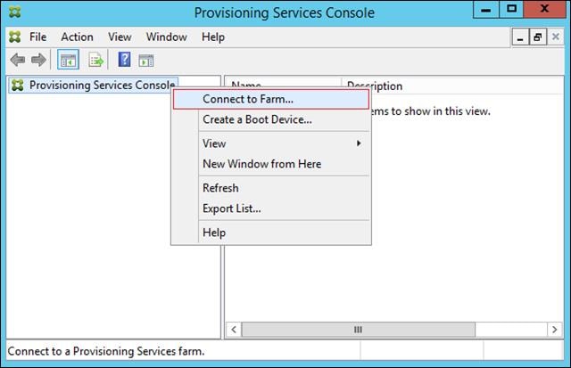
31. Enter localhost for the PVS1 server.
32. Click Connect.
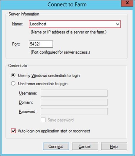
33. Select Store Properties from the drop-down list.
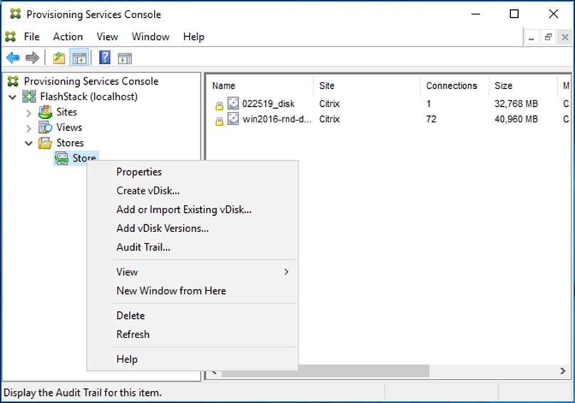
34. In the Store Properties dialog, add the Default store path to the list of Default write cache paths.
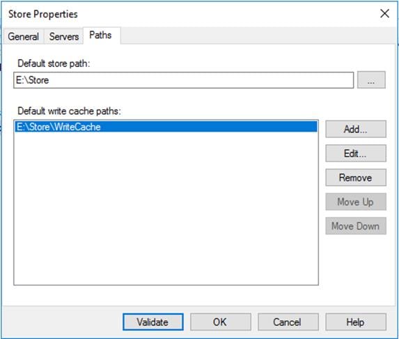
35. Click Validate. If the validation is successful, click Close and then click OK to continue.
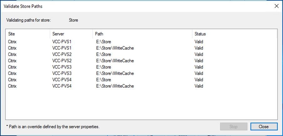
Install XenDesktop Virtual Desktop Agents
Virtual Delivery Agents (VDAs) are installed on the server and workstation operating systems and enable connections for desktops and apps. The following procedure was used to install VDAs for both HVD and HSD environments.
By default, when you install the Virtual Delivery Agent, Citrix User Profile Management is installed silently on master images. (Using profile management as a profile solution is optional but was used for this CVD and is described in a later section.)
To install XenDesktop Virtual Desktop Agents, follow these steps:
1. Launch the XenDesktop installer from the Citrix Virtual Apps and Desktops 7.15.4000 ISO.
2. Click Start on the Welcome Screen.
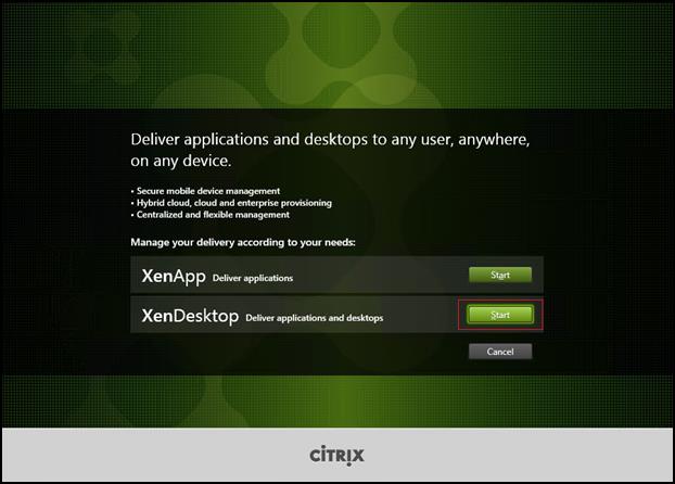
3. To install the VDA for the Hosted Virtual Desktops (VDI), select Virtual Delivery Agent for Windows Desktop OS.
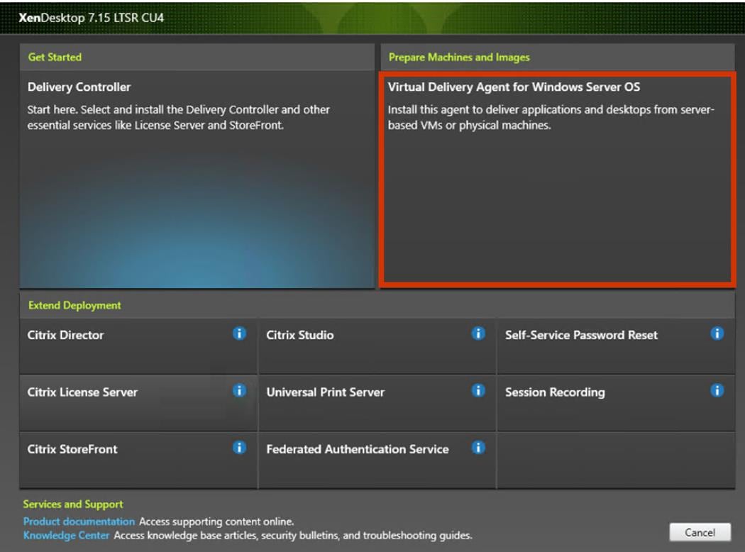
4. After the VDA is installed for Hosted Virtual Desktops, repeat the procedure to install the VDA for Hosted Shared Desktops (RDS). In this case, select Virtual Delivery Agent for Windows Server OS and follow the same basic steps.
5. Select “Create a Master Image.”
6. Click Next.
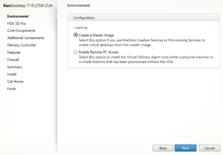
7. For the VDI vDisk, select “No, install the standard VDA.”
8. Click Next.
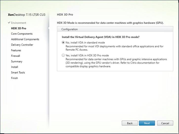
9. Optional: Do not select Citrix Receiver.
10. Click Next.
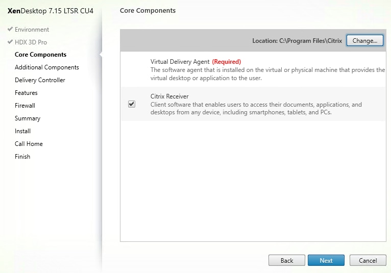
11. Select the additional components required for your image. In this design, only UPM and MCS components were installed on the image.
![]() Deselect Citrix Machine Identity Service when building a master image for use with Citrix Provisioning Services.
Deselect Citrix Machine Identity Service when building a master image for use with Citrix Provisioning Services.
12. Click Next
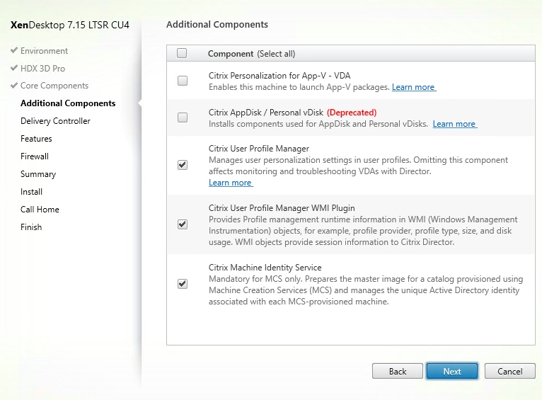
13. Configure Delivery Controllers at this time.
14. Click Next.
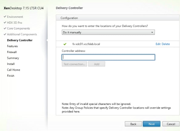
15. Accept the default features.
16. Click Next.
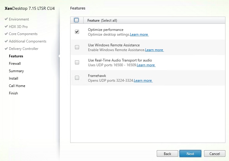
17. Allow the firewall rules to be configured Automatically.
18. Click Next.
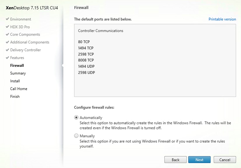
19. Verify the Summary and click Install.
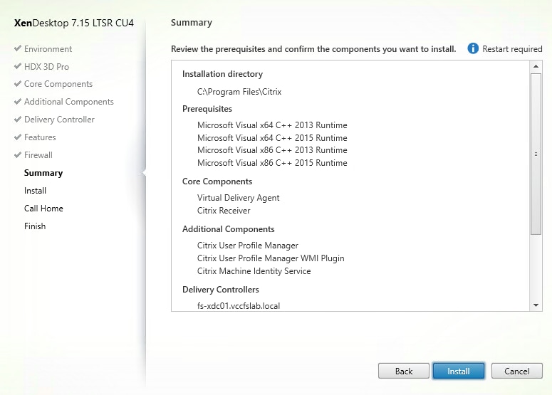
![]() The machine will reboot automatically during installation.
The machine will reboot automatically during installation.
20. (Optional) Configure Smart Tools/Call Home participation.
21. Click Next.
22. Check “Restart Machine.”
23. Click Finish and the machine will reboot automatically.
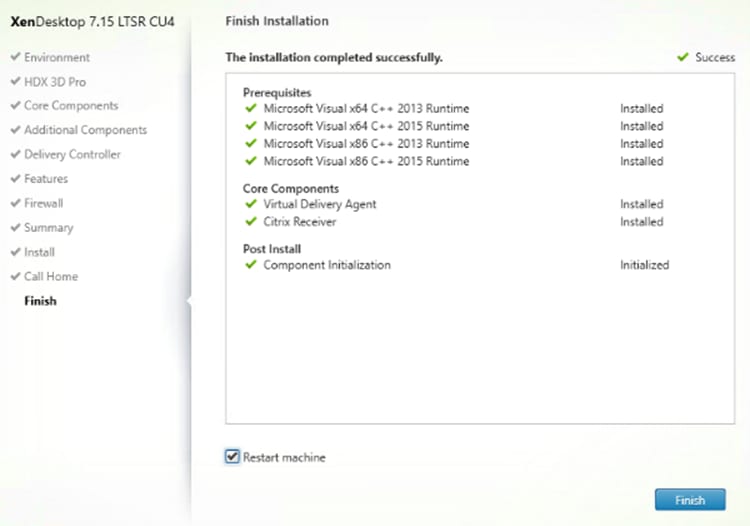
Install the Citrix Provisioning Server Target Device Software
The Master Target Device refers to the target device from which a hard disk image is built and stored on a vDisk. Provisioning Services then streams the contents of the vDisk created to other target devices. This procedure installs the PVS Target Device software that is used to build the RDS and VDI golden images.
To install the Citrix Provisioning Server Target Device software, follow these steps:
![]() The instructions below explain the installation procedure to configure a vDisk for VDI desktops. When you have completed these installation steps, repeat the procedure to configure a vDisk for RDS.
The instructions below explain the installation procedure to configure a vDisk for VDI desktops. When you have completed these installation steps, repeat the procedure to configure a vDisk for RDS.
1. Launch the PVS installer from the Provisioning Services 7.15 LTSR CU4 ISO.
2. Click the Target Device Installation button.
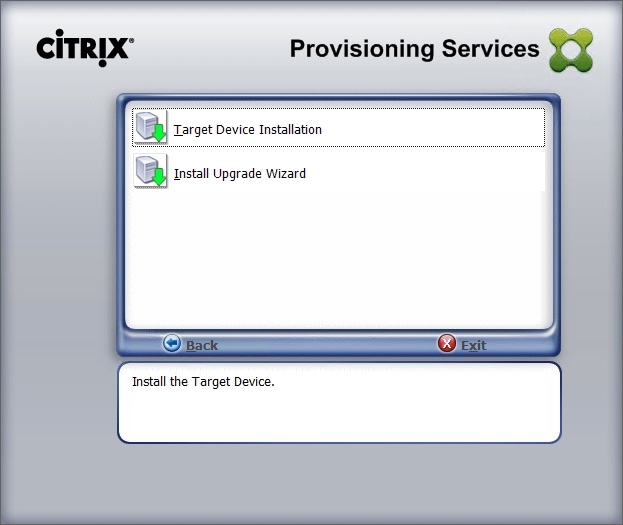
![]() The installation wizard will check to resolve dependencies and then begin the PVS target device installation process.
The installation wizard will check to resolve dependencies and then begin the PVS target device installation process.
3. Click Next.
4. Indicate your acceptance of the license by selecting the “I have read, understand, and accept the terms of the license agreement” radio button.
5. Click Next.
6. Optionally. provide the Customer information.
7. Click Next.
8. Accept the default installation path.
9. Click Next.
10. Click Install.
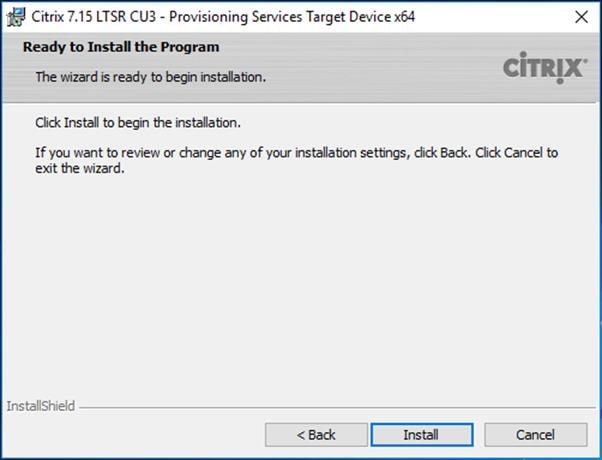
11. Deselect the checkbox to launch the Imaging Wizard and click Finish.
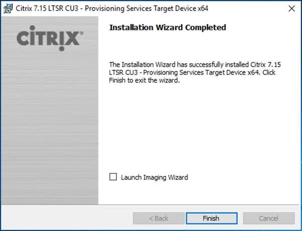
12. Click Yes to reboot the machine.
Create Citrix Provisioning Server vDisks
The PVS Imaging Wizard automatically creates a base vDisk image from the master target device. To create the Citrix Provisioning Server vDisks, follow these steps:
![]() The instructions below describe the process of creating a vDisk for VDI desktops. When you have completed these steps, repeat the procedure to build a vDisk for RDS.
The instructions below describe the process of creating a vDisk for VDI desktops. When you have completed these steps, repeat the procedure to build a vDisk for RDS.
1. The PVS Imaging Wizard's Welcome page appears.
2. Click Next.
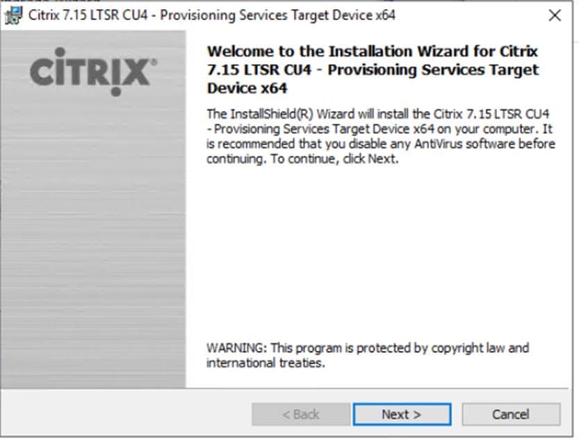
3. The Connect to Farm page appears. Enter the name or IP address of a Provisioning Server within the farm to connect to and the port to use to make that connection.
4. Use the Windows credentials (default) or enter different credentials.
5. Click Next.
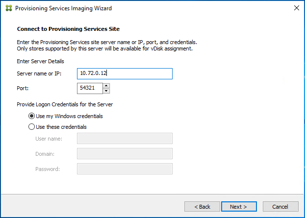
6. Select Create new vDisk.
7. Click Next.
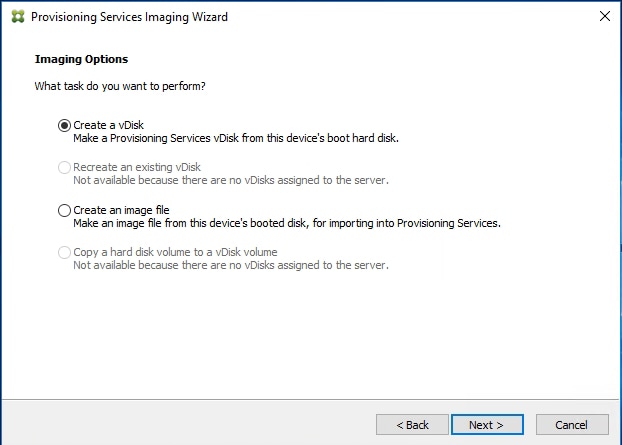
8. The Add Target Device page appears.
9. Select the Target Device Name, the MAC address associated with one of the NICs that was selected when the target device software was installed on the master target device, and the Collection to which you are adding the device.
10. Click Next.
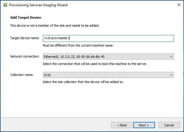
11. The New vDisk dialog displays. Enter the name of the vDisk.
12. Select the Store where the vDisk will reside. Select the vDisk type, either Fixed or Dynamic, from the drop-down list.
![]() This CVD used Dynamic rather than Fixed vDisks.
This CVD used Dynamic rather than Fixed vDisks.
13. Click Next.
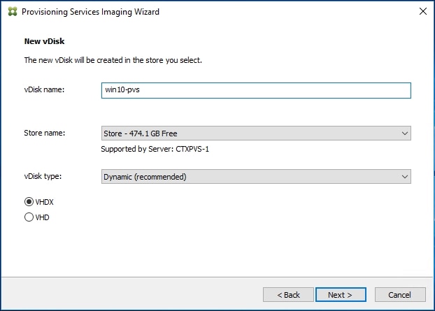
14. On the Microsoft Volume Licensing page, select the volume license option to use for target devices. For this CVD, volume licensing is not used, so select the None button.
15. Click Next.
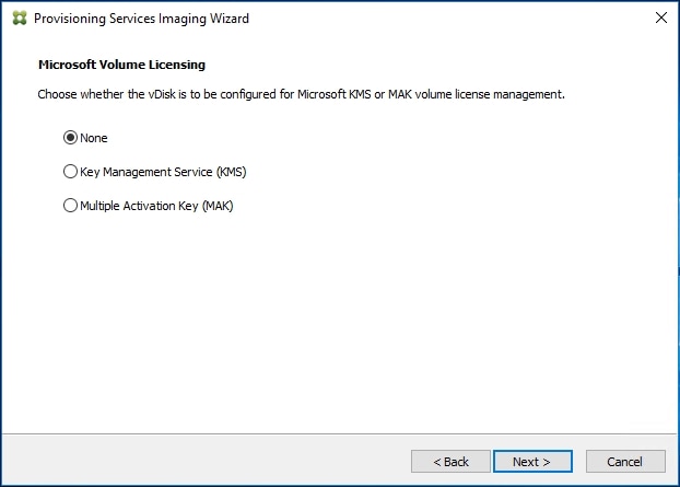
16. Select Image entire boot disk on the Configure Image Volumes page.
17. Click Next.
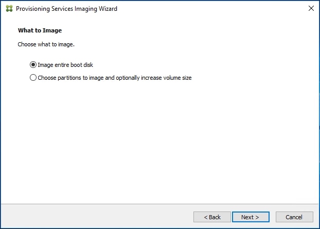
18. Select Optimize for hard disk again for Provisioning Services before imaging on the Optimize Hard Disk for Provisioning Services.
19. Click Next.
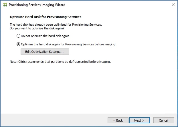
20. Select Create on the Summary page.
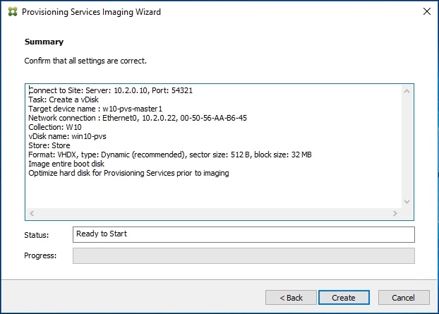
21. Review the configuration and click Continue.
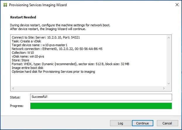
22. When prompted, click No to shut down the machine.
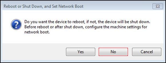
23. Edit the VM settings and select Force BIOS Setup under Boot Options.
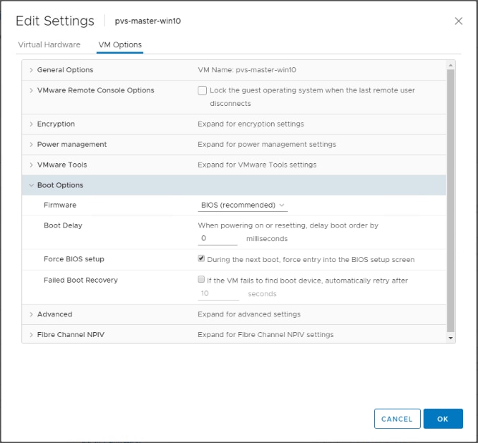
24. Configure the BIOS/VM settings for PXE/network boot, putting Network boot from VMware VMXNET3 at the top of the boot device list.
25. Select Exit Saving Changes.

![]() After restarting the virtual machine, log into the HVD or HSD master target. The PVS imaging process begins, copying the contents of the C: drive to the PVS vDisk located on the server.
After restarting the virtual machine, log into the HVD or HSD master target. The PVS imaging process begins, copying the contents of the C: drive to the PVS vDisk located on the server.
26. If prompted to Restart, select Restart Later.
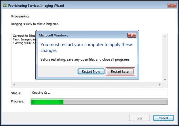
27. A message is displayed when the conversion is complete, click Done.
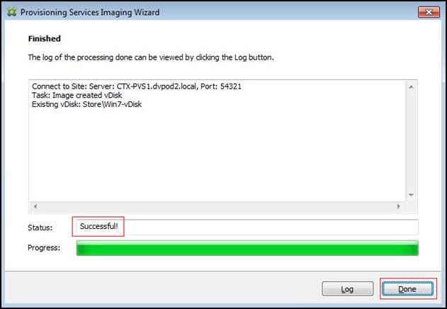
28. Shutdown the virtual machine used as the VDI or RDS master target.
29. Connect to the PVS server and validate that the vDisk image is available in the Store.
30. Right-click the newly created vDisk and select Properties.
31. On the vDisk Properties dialog, change Access mode to “Standard Image (multi-device, read-only access).”
32. Set the Cache Type to “Cache in device RAM with overflow on hard disk.”
33. Set Maximum RAM size (MBs): 128 for HVD and set 2048 MB for HSD vDisk.
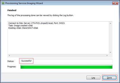
34. Click OK.
![]() Repeat this procedure to create vDisks for both the Hosted VDI Desktops (using the Windows 10 OS image) and the Hosted Shared Desktops (using the Windows Server 2016 image).
Repeat this procedure to create vDisks for both the Hosted VDI Desktops (using the Windows 10 OS image) and the Hosted Shared Desktops (using the Windows Server 2016 image).
Provision Virtual Desktop Machines
Citrix Provisioning Services Streamed VMSetup Wizard
To create PVS streamed virtual desktop machines, follow these steps:
1. Create a Master Target Virtual Machines:
| HVD Master Target VM Parameters |
HSD Master Target VM Parameters |
|
|
|
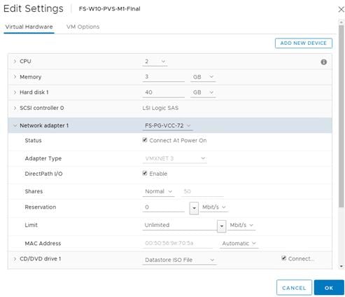
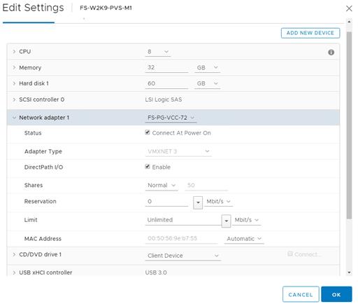
![]() Master Target Virtual Machine Hard disk will be used as write cache disk. It has to be formatted prior to template conversion.
Master Target Virtual Machine Hard disk will be used as write cache disk. It has to be formatted prior to template conversion.
a. Select the Master Target VM from the vSphere Client.
b. Clone the Target VM.
2. Start the XenDesktop Setup Wizard from the Provisioning Services Console:
a. Right-click the Site.
b. Choose Streamed VM Setup Wizard… from the context menu.
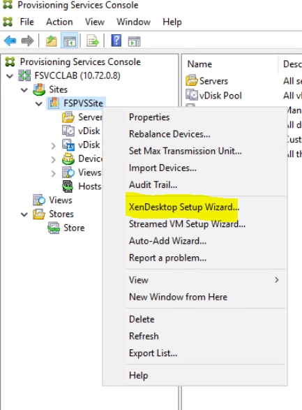
c. Click Next.
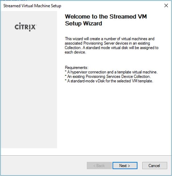
d. Enter the Hypervisor connection details that will be used for the wizard operations.
e. Click Next.
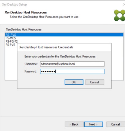
f. Click Next.
g. Select the Template created earlier.
h. Click Next.
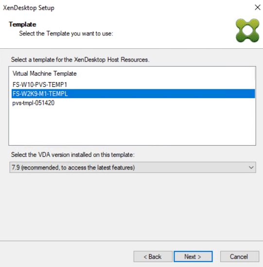
i. Select the virtual disk (vDisk) that will be used to stream the provisioned virtual machines.
j. Click Next.

k. Select Collection where the machines will be placed.
l. Click Next.
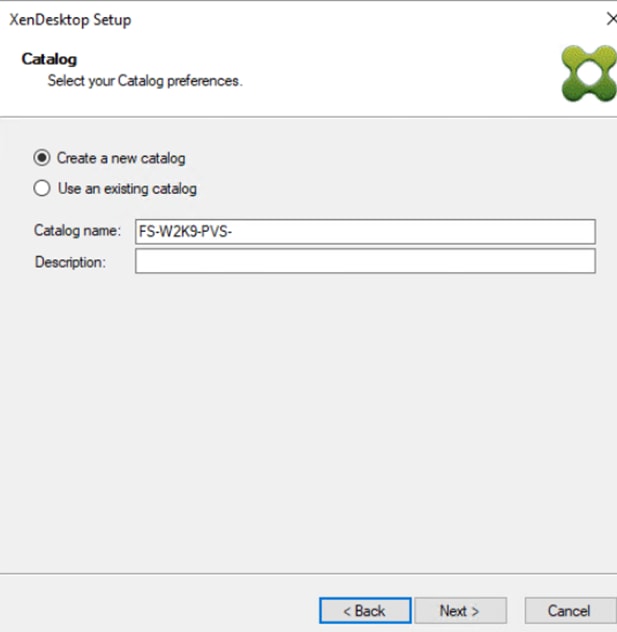
m. On the Virtual machines dialog, specify:
§ The number of virtual machines to create. (Note that it is recommended to create 200 or less per provisioning run. Create a single virtual machine at first to verify the procedure.)
§ Number of vCPUs for the virtual machine (2 for HVD, 9 for HSD)
§ The amount of memory for the virtual machine (2GB for HVD, 24GB for HSD)
n. Click Next.
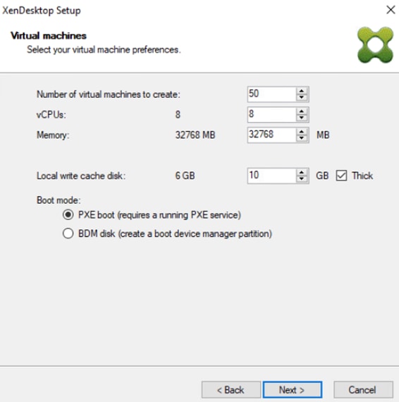
o. Select the Create new accounts radio button.
p. Click Next.
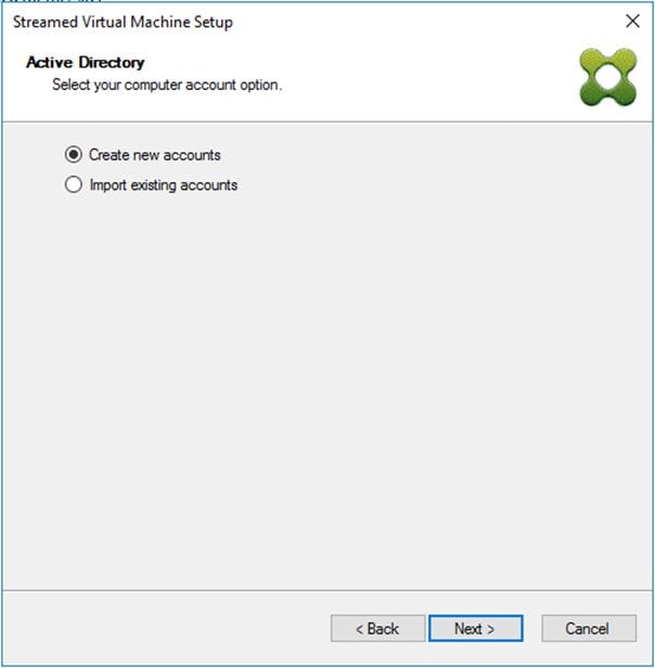
q. Specify the Active Directory Accounts and Location. This is where the wizard should create computer accounts.
r. Provide the Account naming scheme. An example name is shown in the text box below the naming scheme selection location.
s. Click Next.
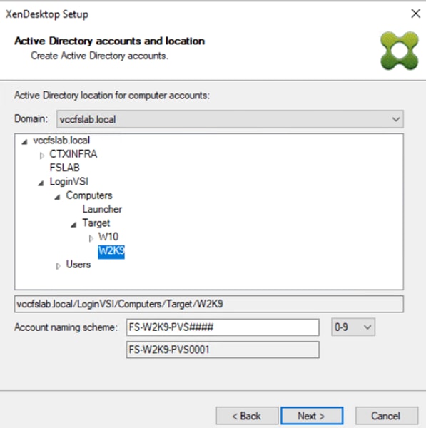
t. Click Finish to begin the virtual machine creation.
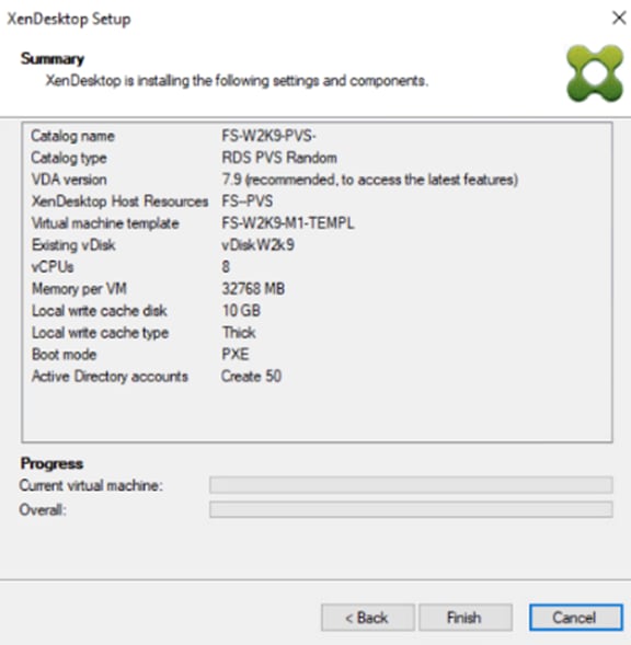
u. When the wizard is done provisioning the virtual machines, click Done.
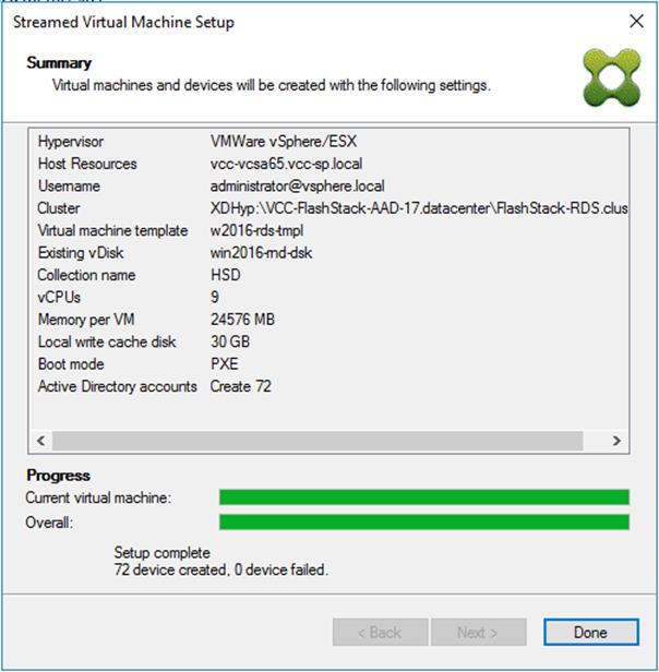
3. When the wizard is done provisioning the virtual machines, add virtual machines to the Machine Catalog on the XenDesktop Controller:
a. Connect to a XenDesktop server and launch Citrix Studio.
b. Select Machine Catalogs in the Studio navigation pane.
c. Select a machine catalog right-click and then select Add machines.
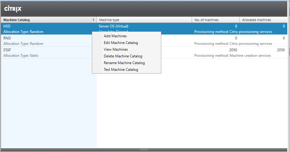
d. Connect to a Provisioning Services server hosting virtual machine records.
e. Select Provisioning Services Device Collection contains the virtual machine records that will be added to the catalog.
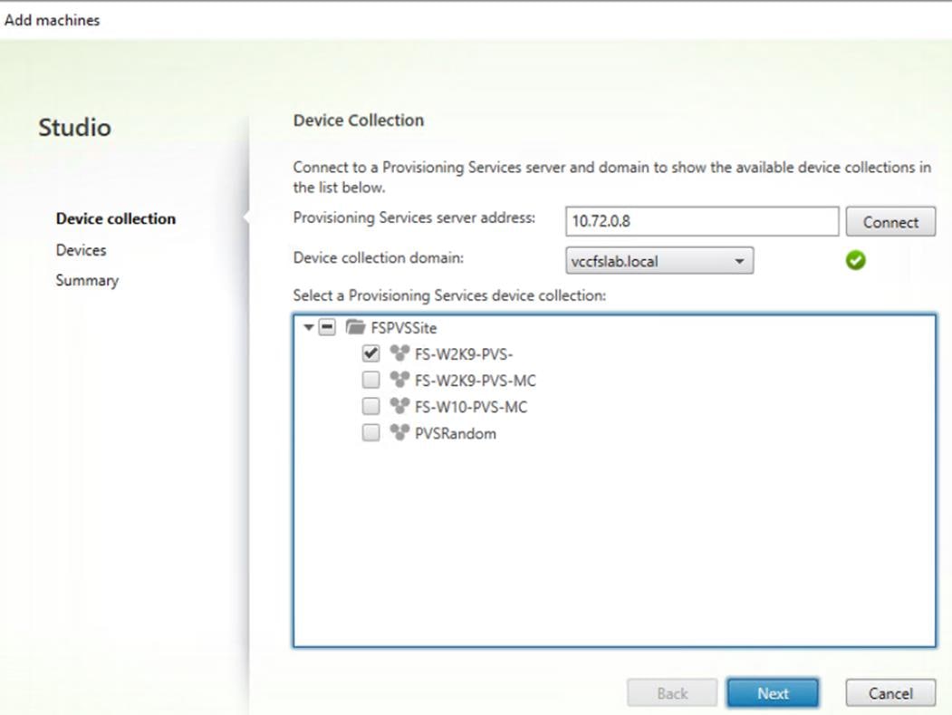
f. Inspect the devices that will be added and click Next.
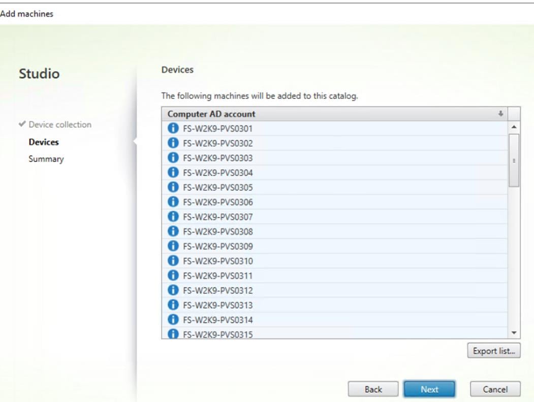
g. Click Finish on the Summary page.
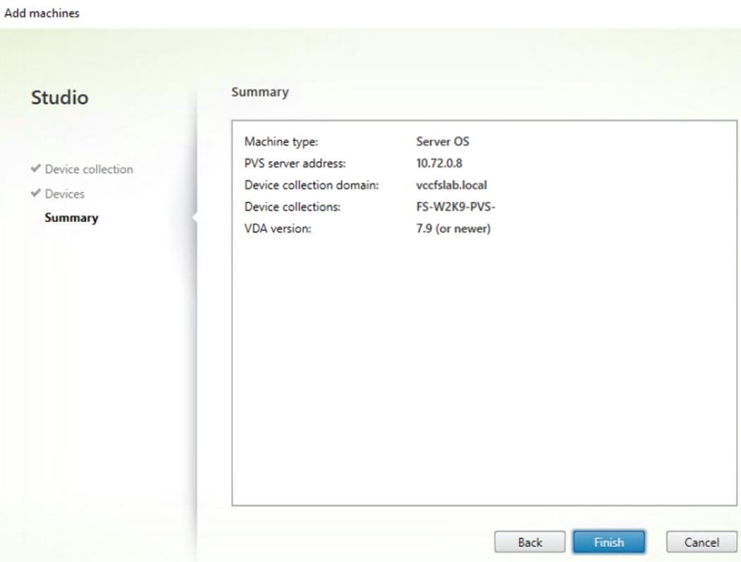
Citrix Machine Creation Services
To configure the Machine Catalog Setup, follow these steps:
1. Connect to a XenDesktop server and launch Citrix Studio.
2. Choose Create Machine Catalog from the Actions pane.
3. Click Next.
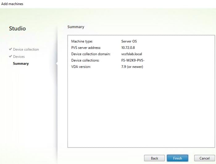
4. Select Desktop OS.
5. Click Next.
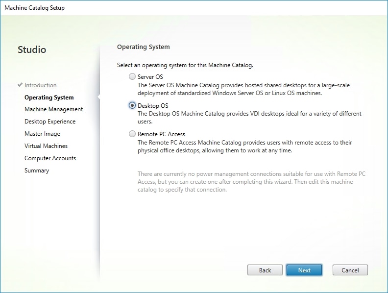
6. Select appropriate machine management.
7. Click Next.
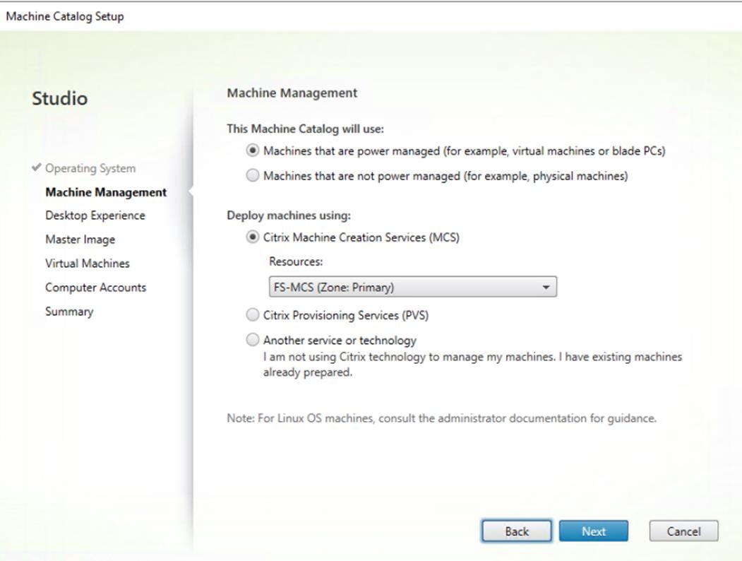
8. Select Static, Dedicated Virtual Machine for Desktop Experience.
9. Click Next.
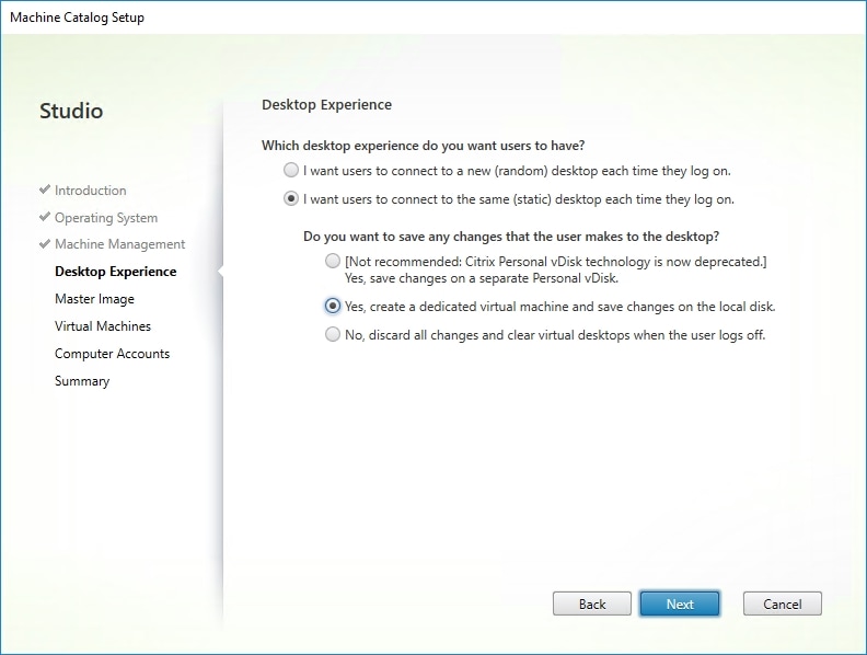
10. Select a Virtual Machine to be used for Catalog Master Image.
11. Click Next.
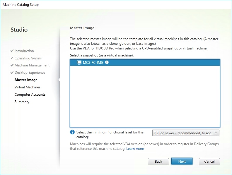
12. Specify the number of desktops to create and machine configuration.
13. Set amount of memory (MB) to be used by virtual desktops.
14. Select Full Copy for machine copy mode.
15. Click Next.
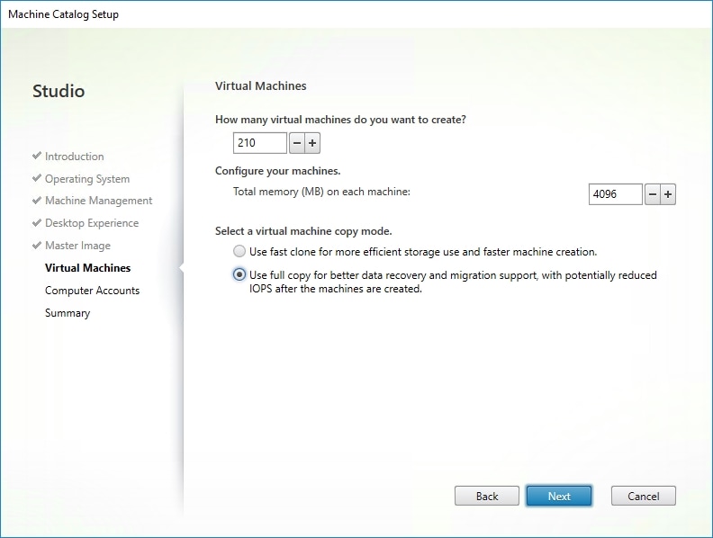
16. Specify the AD account naming scheme and OU where accounts will be created.
17. Click Next.
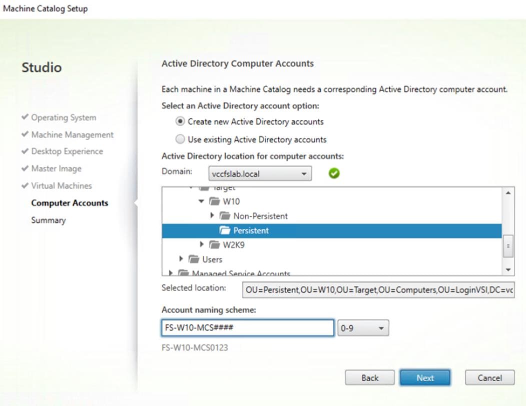
18. On the Summary page specify Catalog name and click Finish to start the deployment.
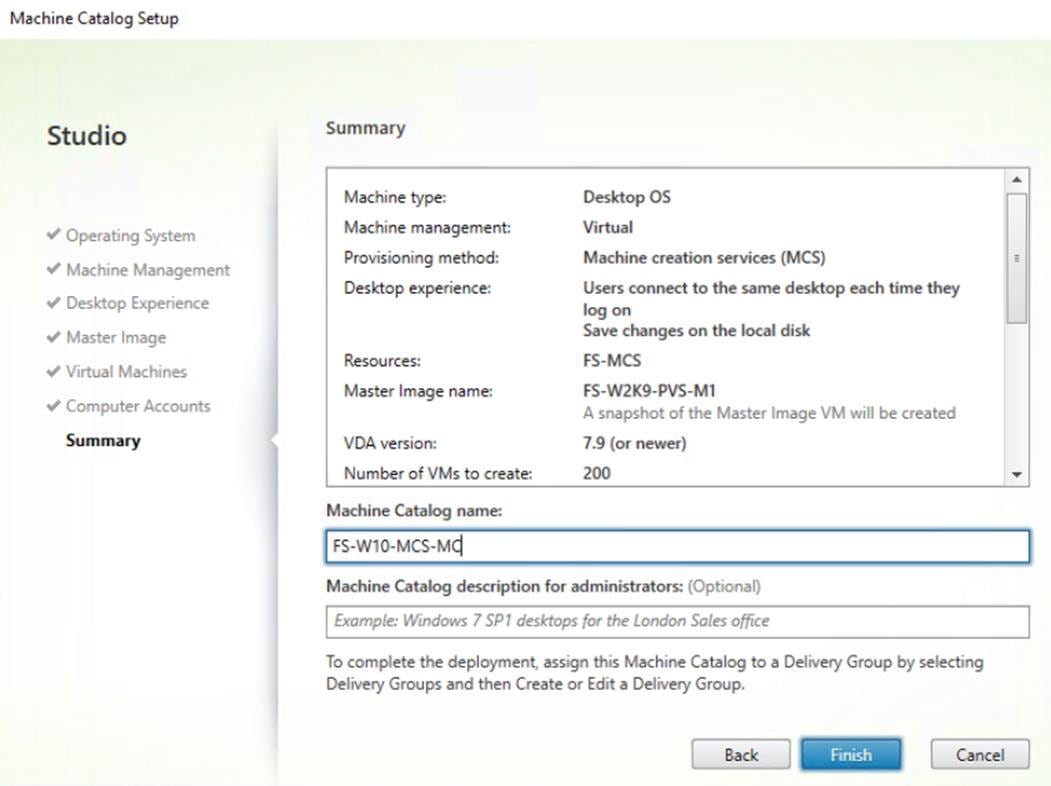
Create Delivery Groups
Delivery Groups are collections of machines that control access to desktops and applications. With Delivery Groups, you can specify which users and groups can access which desktops and applications.
To create delivery groups, follow these steps:
![]() The instructions below outline the procedure to create a Delivery Group for persistent VDI desktops. When you have completed these steps, repeat the procedure to a Delivery Group for RDS desktops.
The instructions below outline the procedure to create a Delivery Group for persistent VDI desktops. When you have completed these steps, repeat the procedure to a Delivery Group for RDS desktops.
1. Connect to a XenDesktop server and launch Citrix Studio.
2. Choose Create Delivery Group from the drop-down list.
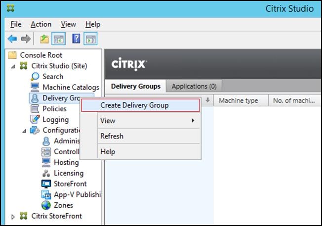
3. Click Next.
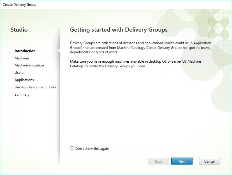
4. Specify the Machine Catalog and increment the number of machines to add.
5. Click Next.
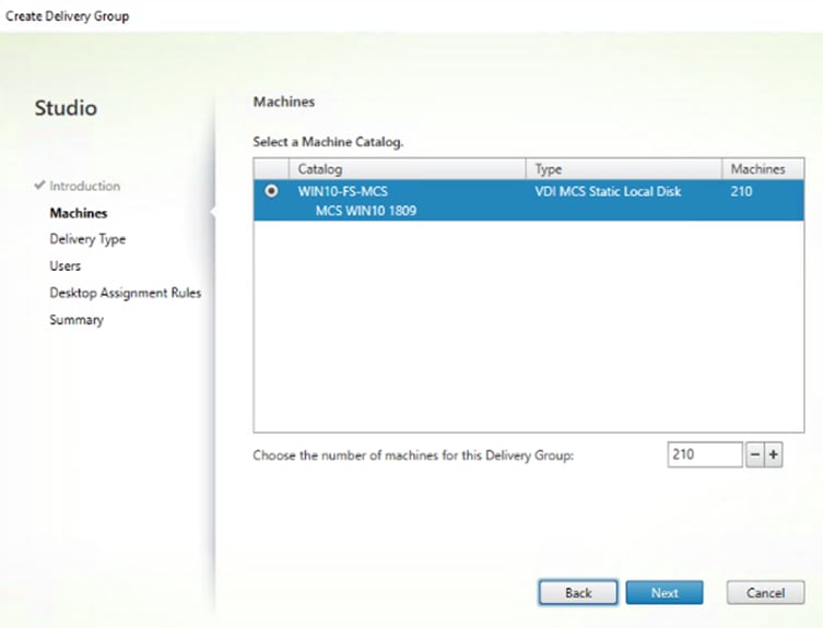
6. Specify what the machines in the catalog will deliver: Desktops, Desktops and Applications, or Applications.
7. Select Desktops.
8. Click Next.
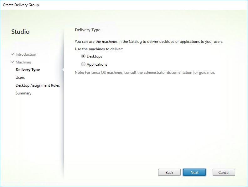
9. To make the Delivery Group accessible, you must add users, select Allow any authenticated users to use this Delivery Group.
10. User assignment can be updated any time after Delivery group creation by accessing Delivery group properties in Desktop Studio.
11. Click Next.
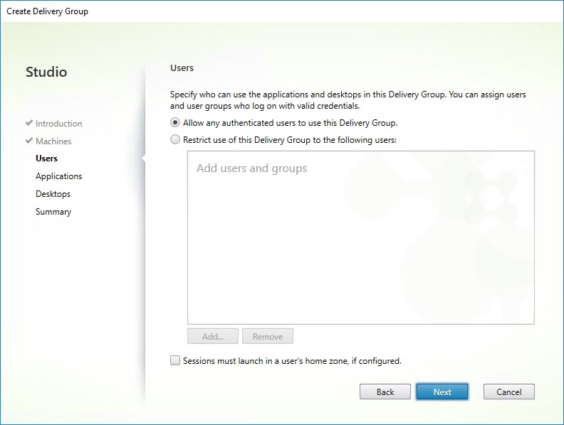
12. Click Next (no applications used in this design).
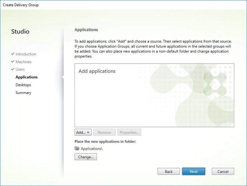
13. Enable Users to access the desktops.
14. Click Next.
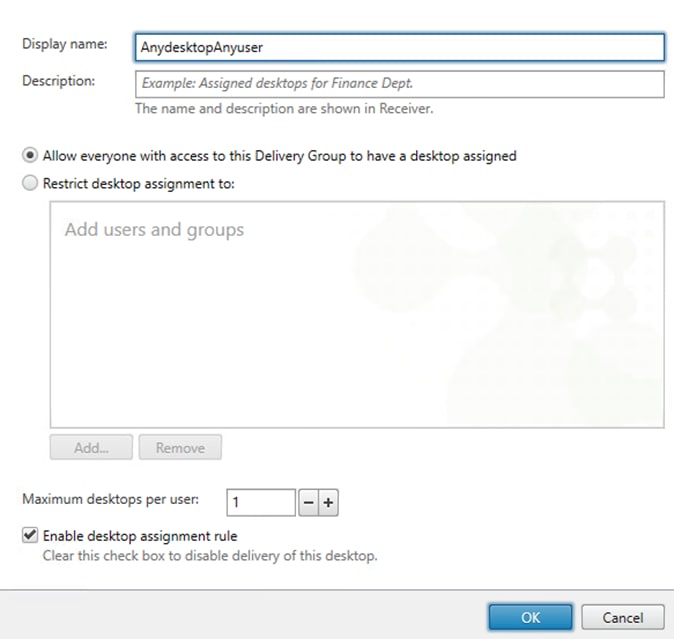
15. On the Summary dialog, review the configuration. Enter a Delivery Group name and a Description (Optional).
16. Click Finish.
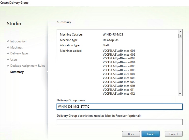
Citrix Studio lists the created Delivery Groups as well as the type, number of machines created, sessions, and applications for each group in the Delivery Groups tab.
17. On the drop-down list, select “Turn on Maintenance Mode.”
Citrix Virtual Apps and Desktops Policies and Profile Management
Policies and profiles allow the Citrix Virtual Apps and Desktops environment to be easily and efficiently customized.
Configure Citrix Virtual Apps and Desktops Policies
Citrix Virtual Apps and Desktops policies control user access and session environments, and are the most efficient method of controlling connection, security, and bandwidth settings. You can create policies for specific groups of users, devices, or connection types with each policy. Policies can contain multiple settings and are typically defined through Citrix Studio. (The Windows Group Policy Management Console can also be used if the network environment includes Microsoft Active Directory and permissions are set for managing Group Policy Objects). Figure 49 shows policies for Login VSI testing in this CVD.
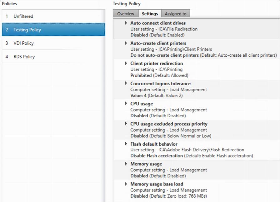
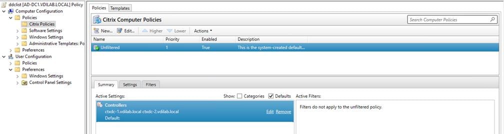
Configuring User Profile Management
Profile management provides an easy, reliable, and high-performance way to manage user personalization settings in virtualized or physical Windows environments. It requires minimal infrastructure and administration and provides users with fast logons and logoffs. A Windows user profile is a collection of folders, files, registry settings, and configuration settings that define the environment for a user who logs on with a particular user account. These settings may be customizable by the user, depending on the administrative configuration.
Examples of settings that can be customized are:
· Desktop settings such as wallpaper and screen saver
· Shortcuts and Start menu setting
· Internet Explorer Favorites and Home Page
· Microsoft Outlook signature
· Printers
Some user settings and data can be redirected by means of folder redirection. However, if folder redirection is not used these settings are stored within the user profile.
The first stage in planning a profile management deployment is to decide on a set of policy settings that together form a suitable configuration for your environment and users. The automatic configuration feature simplifies some of this decision-making for XenDesktop deployments. Screenshots of the User Profile Management interfaces that establish policies for this CVD’s HSD and VDI users (for testing purposes) are shown below. Basic profile management policy settings are documented here:
https://docs.citrix.com/en-us/xenapp-and-xendesktop/7-15-ltsr.html
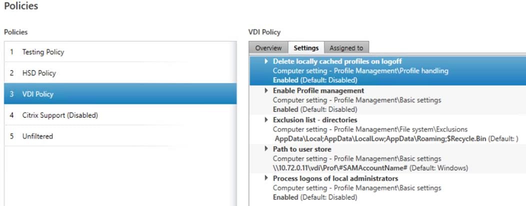
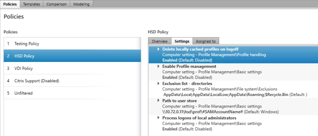
Cisco Intersight Cloud Based Management
Cisco Intersight is Cisco’s new systems management platform that delivers intuitive computing through cloud-powered intelligence. This platform offers a more intelligent level of management that enables IT organizations to analyze, simplify, and automate their environments in ways that were not possible with prior generations of tools. This capability empowers organizations to achieve significant savings in Total Cost of Ownership (TCO) and to deliver applications faster, so they can support new business initiates. The advantages of the model-based management of the Cisco UCS platform plus Cisco Intersight are extended to Cisco UCS servers and Cisco HyperFlex and Cisco HyperFlex Edge systems. Cisco HyperFlex Edge is optimized for remote sites, branch offices, and edge environments.
The Cisco UCS and Cisco HyperFlex platforms use model-based management to provision servers and the associated storage and fabric automatically, regardless of form factor. Cisco Intersight works in conjunction with Cisco UCS Manager and the Cisco® Integrated Management Controller (IMC). By simply associating a model-based configuration with a resource through service profiles, your IT staff can consistently align policy, server personality, and workloads. These policies can be created once and used by IT staff with minimal effort to deploy servers. The result is improved productivity and compliance and lower risk of failures due to inconsistent configuration.
Cisco Intersight will be integrated with data center, hybrid cloud platforms, and services to securely deploy and manage infrastructure resources across data center and edge environments. In addition, Cisco will provide future integrations to third-party operations tools to allow customers to use their existing solutions more effectively.
Table 15 Cisco Intersight Features and Benefits
| Feature |
Benefits |
| Unified management |
● Simplify Cisco UCS, Cisco HyperFlex, Pure Storage, and Cisco Network Insights management from a single management platform. ● Increase scale across data centers and remote locations without additional complexity. ● Use a single dashboard to monitor Cisco UCS and Cisco HyperFlex systems. ● Cisco UCS Manager, Cisco IMC software, Cisco HyperFlex Connect, and Cisco UCS Director tunneling allow access to element managers that do not have local network access. |
| Configuration, provisioning, and server profiles |
● Treat Cisco UCS servers and storage as infrastructure resources that can be allocated and reallocated among application workloads for more dynamic and efficient use of server capacity. ● Create multiple server profiles with just a few clicks or through the available API, automating the provisioning process. ● Clone profiles to quickly provision Cisco UCS C-Series Rack Servers in standalone mode. ● Create, deploy, and manage your Cisco HyperFlex configurations. ● Help ensure consistency and eliminate configuration drift, maintaining standardization across many systems. |
| Inventory information and status |
● Display and report inventory information for Cisco UCS and Cisco HyperFlex systems. ● Use global search to rapidly identify systems based on names, identifiers, and other information. ● Use tagging to associate custom attributes with systems. ● Monitor Cisco UCS and Cisco HyperFlex server alerts and health status across data centers and remote locations. ● View your Cisco HyperFlex configurations. ● Track and manage firmware versions across all connected Cisco UCS and Cisco HyperFlex systems. ● Track and manage software versions and automated patch updates for all claimed Cisco UCS Director software installations. |
| Enhanced support experience |
● Get centralized alerts about failure notifications. ● Automate the generation, forwarding, and analysis of technical support files to the Cisco Technical Assistance Center (TAC) to accelerate the troubleshooting process. |
| Open API |
● A RESTful API that supports the OpenAPI Specification (OAS) to provide full programmability and deep integrations systems. ● The Python and PowerShell SDKs will enable integrations with Ansible, Chef, Puppet, and other DevOps and IT Operations Management (ITOM) tools. ● ServiceNow integration to provide inventory and alerts to the IT Service Management platform. |
| Seamless integration and upgrades |
● Upgrades are available for Cisco UCS, Cisco HyperFlex systems, and Cisco UCS Director software running supported firmware and software versions. ● Upgrades to Cisco Intersight are delivered automatically without requiring the resources of traditional management tool upgrades and disruption to your operations. |
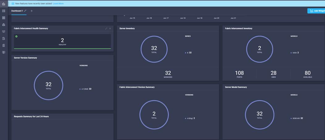

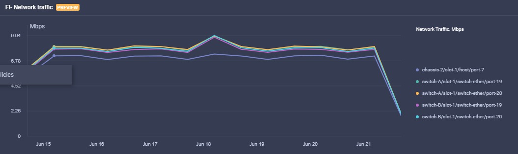
Pure Storage Cisco Intersight FlashArray Connector
Intersight provides connector to manage Pure Storage FlashArray. This can be used to consolidate and analyze large data sets securely collected from customer arrays. This provides the ability to gain meaningful insight from the collected data that can then be shared back to customers in a simple way to enable more informed decisions when managing infrastructure. These can include:
· Predicting resource consumption/growth to simplify capacity planning activities
· Simulating workload placement to better understand and improve asset utilization
· Understanding the resource requirements of new applications before actual deployment.
Pure Storage FlashArray Connector Features
The following are the features of the Pure Storage FlashArray Connector:
1. View general and inventory information – You can view storage device inventory (including FlashArray hardware and Purity software):
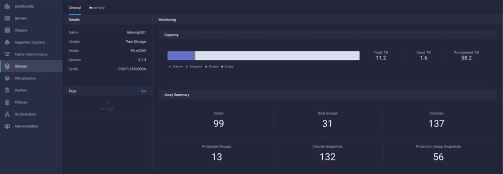
2. Add storage device related widgets to a Dashboard – You can add and rearrange widgets related to storage devices including capacity and inventory information:
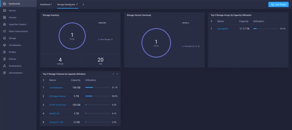
3. Run workflows – Using the workflow designer you can create and execute your own workflows manipulating storage and other infrastructure components together to automate initial deployment/ device reconfiguration:
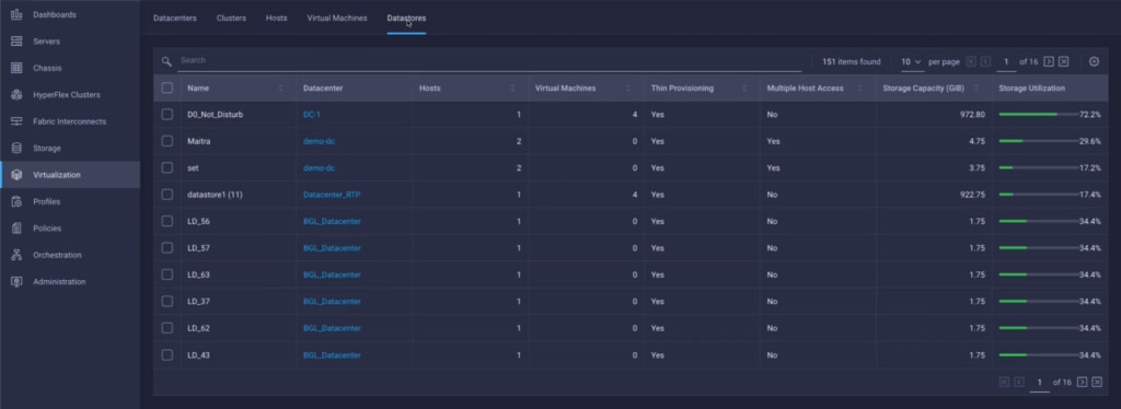
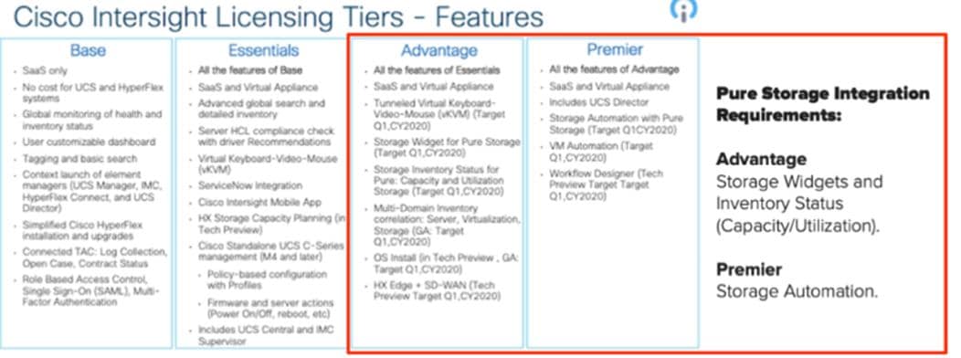
Test Setup, Configuration, and Load Recommendation
In this solution, we tested a single Cisco UCS B200 M5 blade server to validate against the performance of one blade and thirty Cisco UCS B200 M5 blade servers across four chassis to illustrate linear scalability for each workload use case studied.
This CVD is different than previous designs; in previous CVDs we tested mixed load deployed. For this CVD, the following tests were completed separately:
1. Persistent VDI Solution: Develop and test solution for 5000 static(persistent) Windows 10 desktop.
2. Non-Persistent VDI Solution: Develop and test solution for 5500 random(non-persistent) Windows 10 Desktop.
3. HSD Solution: Develop and test solution for 6500 HSD seats with Windows Server 2019.
Single Blade Scalability
Persistent VDI Solution- 200 Seat
This test case validates each workload on a single blade to determine the Recommended Maximum Workload per host server using XenApp/Citrix Virtual Apps and Desktops 7.15 CU4 with 200 Win10 build 1809 Persistent(static) sessions.
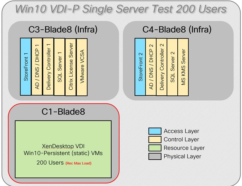
Non-Persistent VDI Solution- 210 Seat
This test case validates each workload on a single blade to determine the Recommended Maximum Workload per host server using XenApp/Citrix Virtual Apps and Desktops 7.15 CU4, Citrix Provisioning Server 7.15.15 with Windows 10 build 1809 is 210.
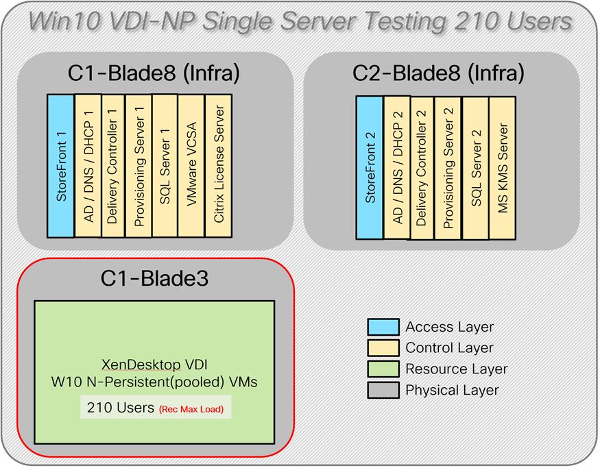
HSD Solution- 260 Seat
This test case validates each workload on a single blade to determine the Recommended Maximum Workload per host server using XenApp/Citrix Virtual Apps and Desktops 7.15 CU4, Citrix Provisioning Server 7.15.15 with Windows Server 2019 build 1809 is 260.
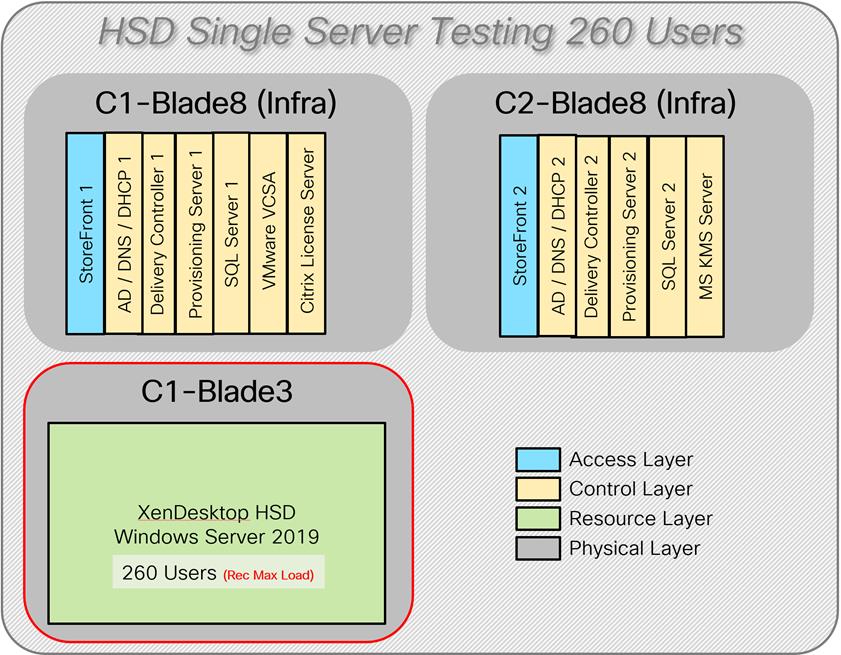
Hardware components:
· Cisco UCS 5108 Blade Server Chassis
· 2 Cisco UCS 6454 4th Gen Fabric Interconnects
· 2 (Infrastructure Hosts) Cisco UCS B200 M5 Blade servers with Intel Xeon Silver 4210 2.20-GHz 10-core processors, 384GB 2933MHz RAM for all host blades
· 1 (HSD/VDI Host) Cisco UCS B200 M5 Blade Servers with Intel Xeon Gold 6230 2.1-GHz 20-core processors, 768GB 2933MHz RAM for all host blades
· Cisco VIC 1440 CNA (1 per blade)
· 2 Cisco Nexus 93180YC-FX Access Switches
· 2 Cisco MDS 9132T 32-Gb 32-Port Fibre Channel Switches
· Pure Storage FlashArray//X70 R2 with dual redundant controllers, with Twenty 1.92TB DirectFlash NVMe drives
Software components:
· Cisco UCS firmware 4.0(4g)
· PureStorage Purity//FA 5.3.6
· VMware ESXi 6.7 Update 3 for host blades
· Citrix Virtual Apps and Desktops 7.15 LTSR CU4 VDI Hosted Virtual Desktops and RDS Hosted Shared Desktops
· Citrix Provisioning Server 7.15 LTSR CU4
· Citrix User Profile Manager
· Microsoft SQL Server 2019
· Microsoft Windows 10 64 bit (1806), 2vCPU, 3 GB RAM, 40 GB HDD
· Microsoft Windows Server 2019 (1809), 8vCPU, 32GB RAM, 60 GB vDisk (master)
· Microsoft Office 2016
· Login VSI 4.1.39 Knowledge Worker Workload (Benchmark Mode)
Full Scale Testing
This test case validates thirty blades with different workloads using XenApp/Citrix Virtual Apps and Desktops 7.15 LTSR CU4. . Server N+1 fault tolerance is factored into this solution for each workload.
Tested workloads are:
1. Windows 10 VDI-Persistent for 5000 users
2. Windows 10 VDI Non-Persistent for 5500 users
3. HSD with Windows Server 2019 6500 users
![]() All workloads were tested on the same hardware.
All workloads were tested on the same hardware.
Hardware components:
· Cisco UCS 5108 Blade Server Chassis
· 2 Cisco UCS 6454 4th Gen Fabric Interconnects
· 2 (Infrastructure Hosts) Cisco UCS B200 M5 Blade servers with Intel Xeon Silver 4210 2.20-GHz 10-core processors, 384GB 2933 MHz RAM for all host blades
· 30 HSD Hosts on Cisco UCS B200 M5 Blade Servers with Intel Xeon Gold 6230 2.1-GHz 20-core processors, 768GB 2933MHz RAM for all host blades
· Cisco VIC 1440 CNA (1 per blade)
· 2 Cisco Nexus 93180YC-FX Access Switches
· 2 Cisco MDS 9132T 32-Gb 32-Port Fibre Channel Switches
· Pure Storage FlashArray//X70 R2 with dual redundant controllers, with Twenty 1.92TB DirectFlash NVMe drives.
Common software components for all workloads:
· Cisco UCS firmware 4.0(4g)
· PureStorage Purity//FA 5.3.6
· VMware ESXi 6.7 Update 3 for host blades
· Citrix Virtual Apps and Desktops 7.15 LTSR CU4
· Citrix User Profile Manager
· Microsoft SQL Server 2019
· Microsoft Office 2016
· Login VSI 4.1.39 Knowledge Worker Workload (Benchmark Mode)
VDI-Persistent(static) for 5000 Users - MCS Full Clone
This test case validates a full-scale test to determine the Recommended Maximum Workload using Citrix Virtual Apps and Desktops 7.15 CU4 with 200 Win10 build 1809 Persistent(static) sessions. The recommended maximum number of seats recommended is 5000 considering Server N+1 fault tolerance.
Software components Specific to VDI- Persistent test:
· Microsoft Windows 10 64 bit (1806), 2vCPU, 3 GB RAM, 40 GB HDD
· Citrix Virtual Apps and Desktops 7.15 LTSR CU4 MCS full clone
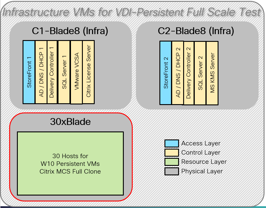
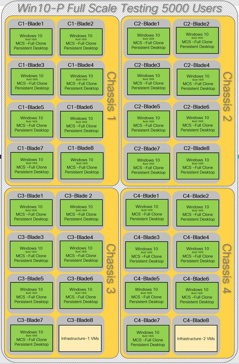
VDI Non-Persistent (Pooled) for 5500 users - PVS
This test case validates a full-sale test to determine the Recommended Maximum Workload using XenApp/Citrix Virtual Apps and Desktops 7.15 CU4 with Win10 build 1809 Non-Persistent(pooled) sessions. The recommended maximum number of seats recommended is 5500 considering Server N+1 fault tolerance.
Software components Specific to VDI- Persistent test:
· Microsoft Windows 10 64 bit (1806), 2vCPU, 3 GB RAM, 40 GB vDisk
· Citrix Virtual Apps and Desktops 7.15 LTSR CU4
· Citrix Provisioning Server 7.15.15.11
· RAM overflow on HDD-128 MB
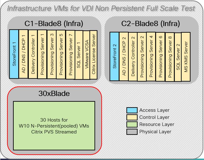
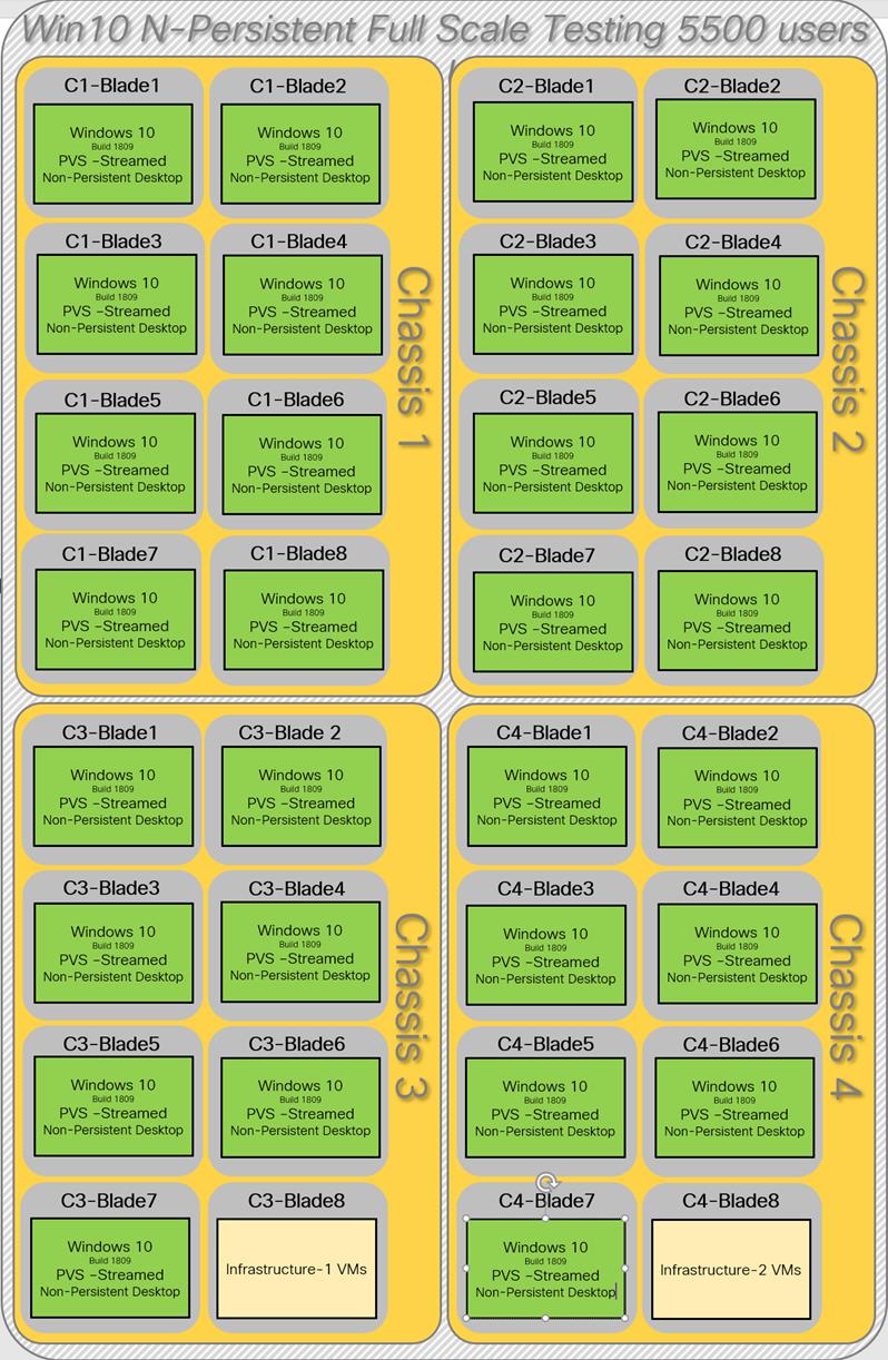
HSD Full Scale Test for 6500 Users
This test case validates a full-scale test to determine the Recommended Maximum Workload using XenApp/Citrix Virtual Apps and Desktops 7.15 CU4 with Windows Server 1809 build 1809 sessions. The recommended maximum number of sessions recommended is 6500 considering Server N+1 fault tolerance.
Software components specific to HSD – full-scale test:
· Microsoft Windows 2019 64 bit (1809), 8vCPU, 32 GB RAM, 60 GB vDisk
· Citrix Virtual Apps and Desktops 7.15 LTSR CU4
· Citrix Provisioning Server 7.15.15.11
· RAM overflow on HDD-1024 MB
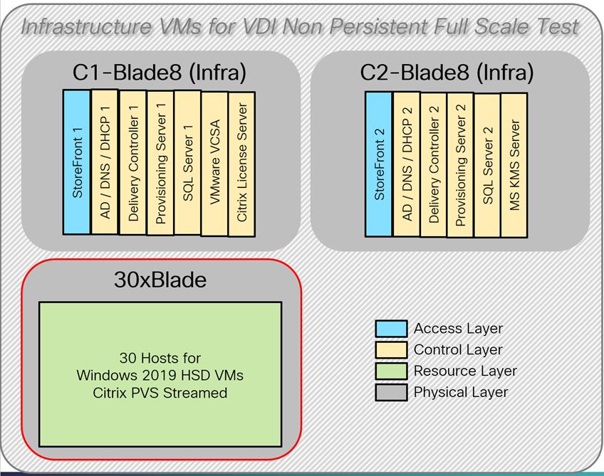
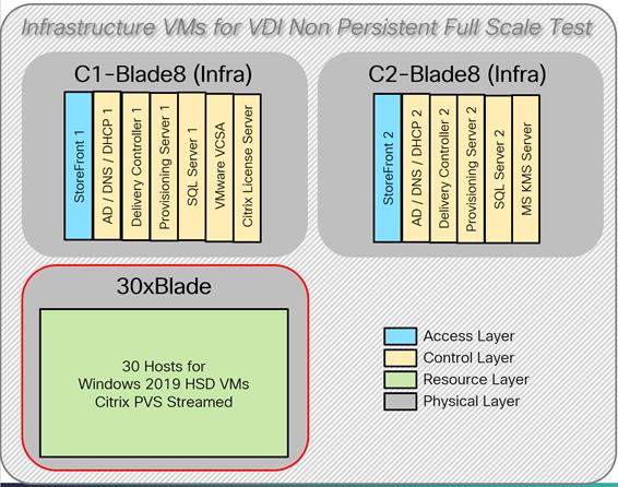
All validation testing was conducted on-site within the Cisco labs in San Jose, California.
The testing results focused on the entire process of the virtual desktop lifecycle by capturing metrics during the desktop boot-up, user logon and virtual desktop acquisition (also referred to as ramp-up,) user workload execution (also referred to as steady state), and user logoff for the HSD Servers Session under test.
Test metrics were gathered from the virtual desktop, storage, and load generation software to assess the overall success of an individual test cycle. Each test cycle was not considered passing unless all of the planned test users completed the ramp-up and steady state phases (described below) and unless all metrics were within the permissible thresholds as noted as success criteria.
Three successfully completed test cycles were conducted for each hardware configuration and results were found to be relatively consistent from one test to the next.
You can obtain additional information and a free test license from http://www.loginvsi.com
Test Procedure
The following protocol was used for each test cycle in this study to ensure consistent results.
Pre-Test Setup for Single and Multi-Blade Testing
All virtual machines were shut down utilizing the XenDesktop Administrator and vCenter.
All Launchers for the test were shut down. They were then restarted in groups of 10 each minute until the required number of launchers was running with the Login VSI Agent at a “waiting for test to start” state.
All VMware ESXi VDI host blades to be tested were restarted prior to each test cycle.
Test Run Protocol
To simulate severe, real-world environments, Cisco requires the log-on and start-work sequence, known as Ramp Up, to complete in 48 minutes. For testing where the user session count exceeds 1000 users, we will now deem the test run successful with up to 0.5% session failure rate.
In addition, Cisco requires that the Login VSI Benchmark method is used for all single server and scale testing. This assures that our tests represent real-world scenarios. For each of the three consecutive runs on single server tests, the same process was followed. To do so, follow these steps:
1. Time 0:00:00 Start PerfMon/Esxtop/XenServer Logging on the following systems:
a. Infrastructure and VDI Host Blades used in the test run
b. vCenter used in the test run
c. All Infrastructure virtual machines used in test run (AD, SQL, brokers, image mgmt., etc.)
2. Time 0:00:10 Start Storage Partner Performance Logging on Storage System.
3. Time 0:05: Boot Virtual Desktops/RDS Virtual Machines using XenDesktop Studio or View Connection server.
![]() The boot rate should be around 10-12 virtual machines per minute per server.
The boot rate should be around 10-12 virtual machines per minute per server.
4. Time 0:06 First machines boot.
5. Time 0:30 Single Server or Scale target number of desktop virtual machines booted on 1 or more blades.
![]() No more than 30 minutes for boot up of 5000 virtual desktops is allowed for MCS VMs and No more than 45 Min allowed for 5500 PVS VMs.
No more than 30 minutes for boot up of 5000 virtual desktops is allowed for MCS VMs and No more than 45 Min allowed for 5500 PVS VMs.
6. Time 0:35 Single Server or Scale target number of desktop virtual machines desktops registered on XD Studio or available on View Connection Server.
7. Virtual machine settling time.
![]() No more than 60 Minutes of rest time is allowed after the last desktop is registered on the XD Studio or available in View Connection Server dashboard. Typically, a 30-40-minute rest period is sufficient.
No more than 60 Minutes of rest time is allowed after the last desktop is registered on the XD Studio or available in View Connection Server dashboard. Typically, a 30-40-minute rest period is sufficient.
8. Time 1:35 Start Login VSI 4.1.x Office Worker Benchmark Mode Test, setting auto-logoff time at 900 seconds, with Single Server or Scale target number of desktop virtual machines utilizing sufficient number of Launchers (at 20-25 sessions/Launcher).
9. Time 2:23 Single Server or Scale target number of desktop virtual machines desktops launched (48 minute benchmark launch rate).
10. Time 2:25 All launched sessions must become active. id test run within this window.
11. Time 2:40 Login VSI Test Ends (based on Auto Logoff 900 Second period designated above).
12. Time 2:55 All active sessions logged off.
13. Time 2:57 All logging terminated; Test complete.
14. Time 3:15 Copy all log files off to archive; Set virtual desktops to maintenance mode through broker; Shutdown all Windows machines.
15. Time 3:30 Reboot all hypervisor hosts.
16. Time 3:45 Ready for the new test sequence.
Success Criteria
Our “pass” criteria for this testing is as follows:
Cisco will run tests at a session count level that effectively utilizes the blade capacity measured by CPU utilization, memory utilization, storage utilization, and network utilization. We will use Login VSI to launch version 4.1.x Office Worker workloads. The number of launched sessions must equal active sessions within two minutes of the last session launched in a test as observed on the VSI Management console.
The Citrix Desktop Studio be monitored throughout the steady state to make sure of the following:
· All running sessions report In Use throughout the steady state
· No sessions move to unregistered, unavailable or available state at any time during steady state
Within 20 minutes of the end of the test, all sessions on all launchers must have logged out automatically and the Login VSI Agent must have shut down. Stuck sessions define a test failure condition.
Cisco requires three consecutive runs with results within +/-1% variability to pass the Cisco Validated Design performance criteria. For white papers written by partners, two consecutive runs within +/-1% variability are accepted. (All test data from partner run testing must be supplied along with the proposed white paper.)
We will publish Cisco Validated Designs with our recommended workload following the process above and will note that we did not reach a VSImax dynamic in our testing. FlashStack Data Center with Cisco UCS and Citrix Virtual Apps and Desktops 7.15 LTSR CU4 on VMware ESXi 6.7 Update 3 Test Results
The purpose of this testing is to provide the data needed to validate Citrix Virtual Apps and Desktops randomly assigned, non-persistent with Citrix Provisioning Services 7.15 LTSR and Citrix Virtual Apps and Desktops Hosted Virtual Desktop (VDI) statically assigned, persistent full-clones models using ESXi and vCenter to virtualize Microsoft Windows 10 desktops and Microsoft Windows Server 2019 sessions on Cisco UCS B200 M5 Blade Servers using the Pure Storage FlashArray//X70 R2 storage system.
The information contained in this section provides data points that a customer may reference in designing their own implementations. These validation results are an example of what is possible under the specific environment conditions outlined here, and do not represent the full characterization of Citrix products with VMware vSphere.
Four test sequences, each containing three consecutive test runs generating the same result, were performed to establish single blade performance and multi-blade, linear scalability.
VSImax 4.1.x Description
The philosophy behind Login VSI is different from conventional benchmarks. In general, most system benchmarks are steady state benchmarks. These benchmarks execute one or multiple processes, and the measured execution time is the outcome of the test. Simply put: the faster the execution time or the bigger the throughput, the faster the system is according to the benchmark.
Login VSI is different in approach. Login VSI is not primarily designed to be a steady state benchmark (however, if needed, Login VSI can act like one). Login VSI was designed to perform benchmarks for HSD or VDI workloads through system saturation. Login VSI loads the system with simulated user workloads using well known desktop applications like Microsoft Office, Internet Explorer, and Adobe PDF reader. By gradually increasing the amount of simulated users, the system will eventually be saturated. Once the system is saturated, the response time of the applications will increase significantly. This latency in application response times show a clear indication whether the system is (close to being) overloaded. As a result, by nearly overloading a system it is possible to find out what its true maximum user capacity is.
After a test is performed, the response times can be analyzed to calculate the maximum active session/desktop capacity. Within Login VSI this is calculated as VSImax. When the system is coming closer to its saturation point, response times will rise. When reviewing the average response time, it will be clear the response times escalate at saturation point.
This VSImax is the “Virtual Session Index (VSI)”. With Virtual Desktop Infrastructure (VDI) and Terminal Services (RDS) workloads this is valid and useful information. This index simplifies comparisons and makes it possible to understand the true impact of configuration changes on hypervisor host or guest level.
Server-Side Response Time Measurements
It is important to understand why specific Login VSI design choices have been made. An important design choice is to execute the workload directly on the target system within the session instead of using remote sessions. The scripts simulating the workloads are performed by an engine that executes workload scripts on every target system and are initiated at logon within the simulated user’s desktop session context.
An alternative to the Login VSI method would be to generate user actions client side through the remoting protocol. These methods are always specific to a product and vendor dependent. More importantly, some protocols simply do not have a method to script user actions client side.
For Login VSI, the choice has been made to execute the scripts completely server side. This is the only practical and platform independent solution, for a benchmark like Login VSI.
Calculating VSImax v4.1.x
The simulated desktop workload is scripted in a 48 minute loop when a simulated Login VSI user is logged on, performing generic Office worker activities. After the loop is finished it will restart automatically. Within each loop, the response times of sixteen specific operations are measured in a regular interval: sixteen times in within each loop. The response times of these five operations are used to determine VSImax.
The five operations from which the response times are measured are:
· Notepad File Open (NFO)
Loading and initiating VSINotepad.exe and opening the openfile dialog. This operation is handled by the OS and by the VSINotepad.exe itself through execution. This operation seems almost instant from an end-user’s point of view.
· Notepad Start Load (NSLD)
Loading and initiating VSINotepad.exe and opening a file. This operation is also handled by the OS and by the VSINotepad.exe itself through execution. This operation seems almost instant from an end-user’s point of view.
· Zip High Compression (ZHC)
This action copy's a random file and compresses it (with 7zip) with high compression enabled. The compression will very briefly spike CPU and disk IO.
· Zip Low Compression (ZLC)
This action copy's a random file and compresses it (with 7zip) with low compression enabled. The compression will very briefly disk IO and creates some load on the CPU.
· CPU
Calculates a large array of random data and spikes the CPU for a short period of time.
These measured operations within Login VSI do hit considerably different subsystems such as CPU (user and kernel), Memory, Disk, the OS in general, the application itself, print, GDI, etc. These operations are specifically short by nature. When such operations become consistently long: the system is saturated because of excessive queuing on any kind of resource. As a result, the average response times will then escalate. This effect is clearly visible to end-users. If such operations consistently consume multiple seconds the user will regard the system as slow and unresponsive.


When the test is finished, VSImax can be calculated. When the system is not saturated, and it could complete the full test without exceeding the average response time latency threshold, VSImax is not reached and the amount of sessions ran successfully.
The response times are very different per measurement type, for instance Zip with compression can be around 2800 ms, while the Zip action without compression can only take 75ms. These response times of these actions are weighted before they are added to the total. This ensures that each activity has an equal impact on the total response time.
In comparison to previous VSImax models, this weighting much better represents system performance. All actions have very similar weight in the VSImax total. The following weighting of the response times is applied.
The following actions are part of the VSImax v4.1.x calculation and are weighted as follows (US notation):
· Notepad File Open (NFO): 0.75
· Notepad Start Load (NSLD): 0.2
· Zip High Compression (ZHC): 0.125
· Zip Low Compression (ZLC): 0.2
· CPU: 0.75
This weighting is applied on the baseline and normal Login VSI response times.
With the introduction of Login VSI 4.1.x, we also created a new method to calculate the basephase of an environment. With the new workloads (Taskworker, Powerworker, and so on) enabling 'basephase' for a more reliable baseline has become obsolete. The calculation is explained below. In total the 15 lowest VSI response time samples are taken from the entire test, the lowest 2 samples are removed. and the 13 remaining samples are averaged. The result is the Baseline. To summarize:
· Take the lowest 15 samples of the complete test
· From those 15 samples remove the lowest 2
· Average the 13 results that are left is the baseline
The VSImax average response time in Login VSI 4.1.x is calculated on the number of active users that are logged on the system.
Always a 5 Login VSI response time samples are averaged + 40 percent of the amount of “active” sessions. For example, if the active sessions are 60, then latest 5 + 24 (=40 percent of 60) = 31 response time measurement is used for the average calculation.
To remove noise (accidental spikes) from the calculation, the top 5 percent and bottom 5 percent of the VSI response time samples are removed from the average calculation, with a minimum of 1 top and 1 bottom sample. As a result, with 60 active users, the last 31 VSI response time sample are taken. From those 31 samples, the top 2 samples are removed, and the lowest 2 results are removed (5 percent of 31 = 1.55, rounded to 2). At 60 users the average is then calculated over the 27 remaining results.
VSImax v4.1.x is reached when the VSIbase + a 1000 ms latency threshold is not reached by the average VSI response time result. Depending on the tested system, VSImax response time can grow 2 - 3x the baseline average. In end-user computing, a 3x increase in response time in comparison to the baseline is typically regarded as the maximum performance degradation to be considered acceptable.
In VSImax v4.1.x this latency threshold is fixed to 1000ms, this allows better and fairer comparisons between two different systems, especially when they have different baseline results. Ultimately, in VSImax v4.1.x, the performance of the system is not decided by the total average response time, but by the latency is has under load. For all systems, this is now 1000ms (weighted).
The threshold for the total response time is: average weighted baseline response time + 1000ms.
When the system has a weighted baseline response time average of 1500ms, the maximum average response time may not be greater than 2500ms (1500+1000). If the average baseline is 3000 the maximum average response time may not be greater than 4000ms (3000+1000).
When the threshold is not exceeded by the average VSI response time during the test, VSImax is not hit and the number of sessions ran successfully. This approach is fundamentally different in comparison to previous VSImax methods, as it was always required to saturate the system beyond VSImax threshold.
Lastly, VSImax v4.1.x is now always reported with the average baseline VSI response time result. For example: “The VSImax v4.1.x was 125 with a baseline of 1526ms”. This helps considerably in the comparison of systems and gives a more complete understanding of the system. The baseline performance helps to understand the best performance the system can give to an individual user. VSImax indicates what the total user capacity is for the system. These two are not automatically connected and related:
When a server with a very fast dual core CPU, running at 3.6 GHz, is compared to a 10 core CPU, running at 2,26 GHz, the dual core machine will give and individual user better performance than the 10-core machine. This is indicated by the baseline VSI response time. The lower this score is, the better performance an individual user can expect.
However, the server with the slower 10 core CPU will easily have a larger capacity than the faster dual core system. This is indicated by VSImax v4.1.x, and the higher VSImax is, the larger overall user capacity can be expected.
With Login VSI 4.1.x a new VSImax method is introduced: VSImax v4.1.x. This methodology gives much better insight into system performance and scales to extremely large systems.
Single-Server Recommended Maximum Workload
For the Citrix Virtual Apps and Desktops 7.15 Hosted Virtual Desktop use cases, a recommended maximum workload was determined by the Login VSI Knowledge Worker Workload in VSI Benchmark Mode end user experience measurements and blade server operating parameters.
Our recommendation is that the Login VSI Average Response and VSI Index Average should not exceed the Baseline plus 2000 milliseconds to ensure that end user experience is outstanding. Additionally, during steady state, the processor utilization should average no more than 90-95 percent.
![]() Memory should never be oversubscribed for Desktop Virtualization workloads.
Memory should never be oversubscribed for Desktop Virtualization workloads.
Figure 66 Phases of Test Runs
| Test Phase |
Description |
| Boot |
Start all HSD and VDI virtual machines at the same time |
| Idle |
The rest time after the last desktop is registered on the XD Studio. (typically, a 30-40 minute, <60 min) |
| Logon |
The Login VSI phase of the test is where sessions are launched and start executing the workload over a 48 minutes duration |
| Steady state |
The steady state phase is where all users are logged in and performing various workload tasks such as using Microsoft Office, Web browsing, PDF printing, playing videos, and compressing files (typically for the 15-minute duration) |
| Logoff |
Sessions finish executing the Login VSI workload and logoff |
Single-Server Recommended Maximum Workload Testing
This section provides the key performance metrics that were captured on the Cisco UCS host blades during the single server testing to determine the Recommended Maximum Workload per host server. The single server testing comprised of following three tests:
1. 200 VDI Persistent sessions.
2. 210 VDI Non-Persistent sessions
3. 260 HSD sessions
Single-Server Recommended Maximum Workload for Persistent VDI Desktop - 200 Users
The recommended maximum workload for a Cisco UCS B200 M5 blade server with dual Intel Xeon Gold 6140 processors, 768GB 2933 MHz RAM is 200 Windows 10 64-bit Build 1809 persistent VDI virtual machines with 2 vCPU and 3 GB RAM. All VMs deployed using Citrix Machine Cloning Service.
Login VSI performance data is as follows:
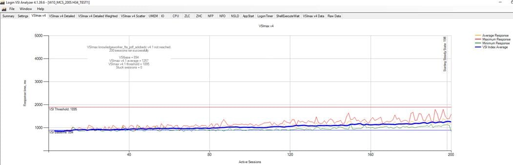
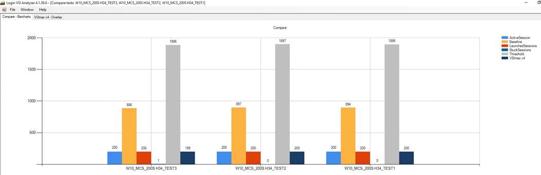
Performance data for the server running the workload is as follows:
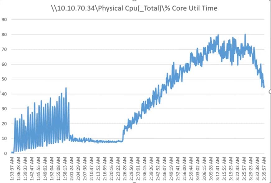
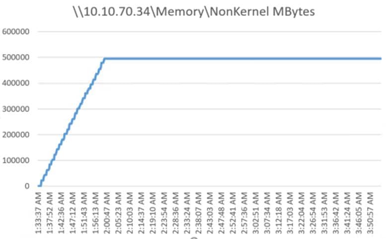
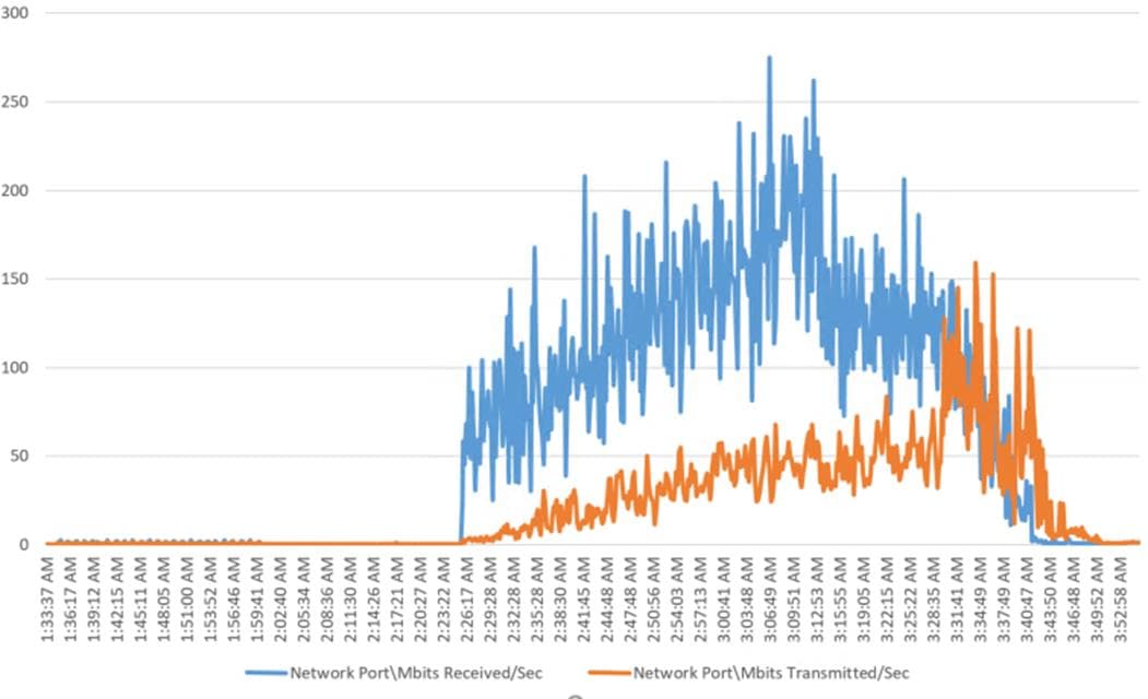
Single-Server Recommended Maximum Workload for HVD Non-Persistent with 210 Users
The recommended maximum workload for a Cisco UCS B200 M5 blade server with dual Intel Xeon Gold 6140 processors, 768GB 2666MHz RAM is 205 Windows 10 64-bit HVD non-persistent virtual machines with 2 vCPU and 2GB RAM.
Login VSI performance data is as follows.
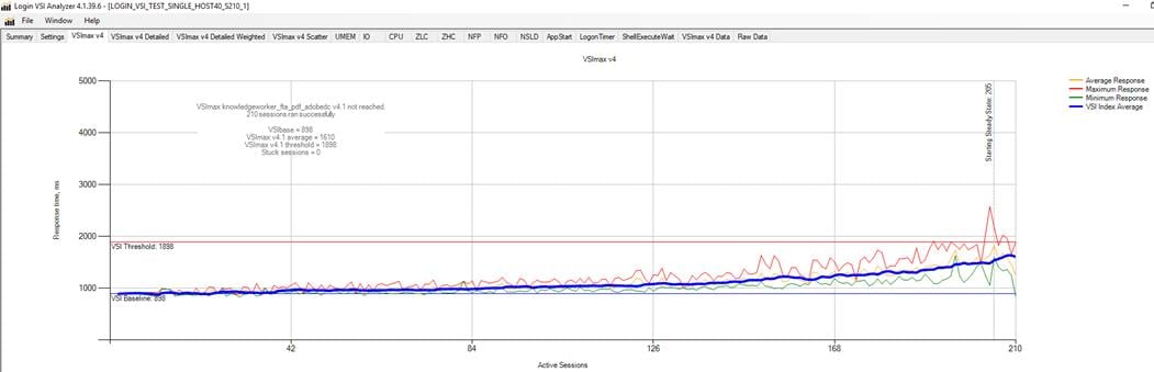
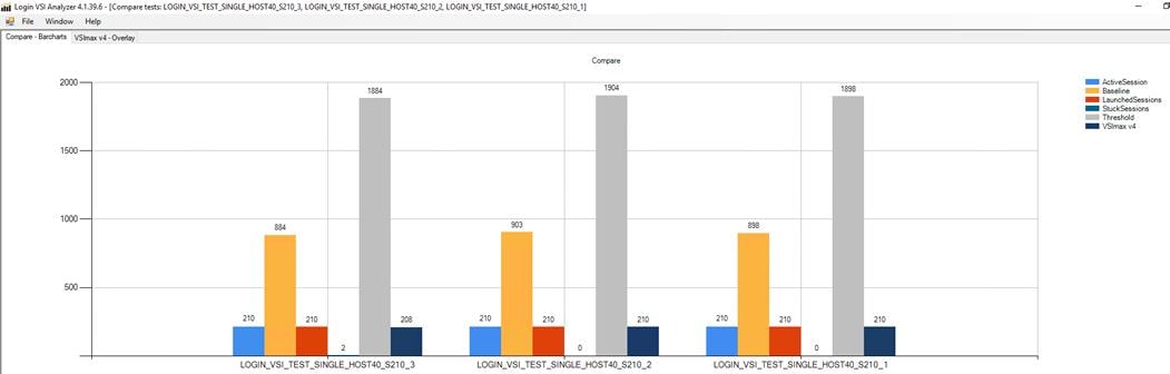
Performance data for the server running the workload is as follows:
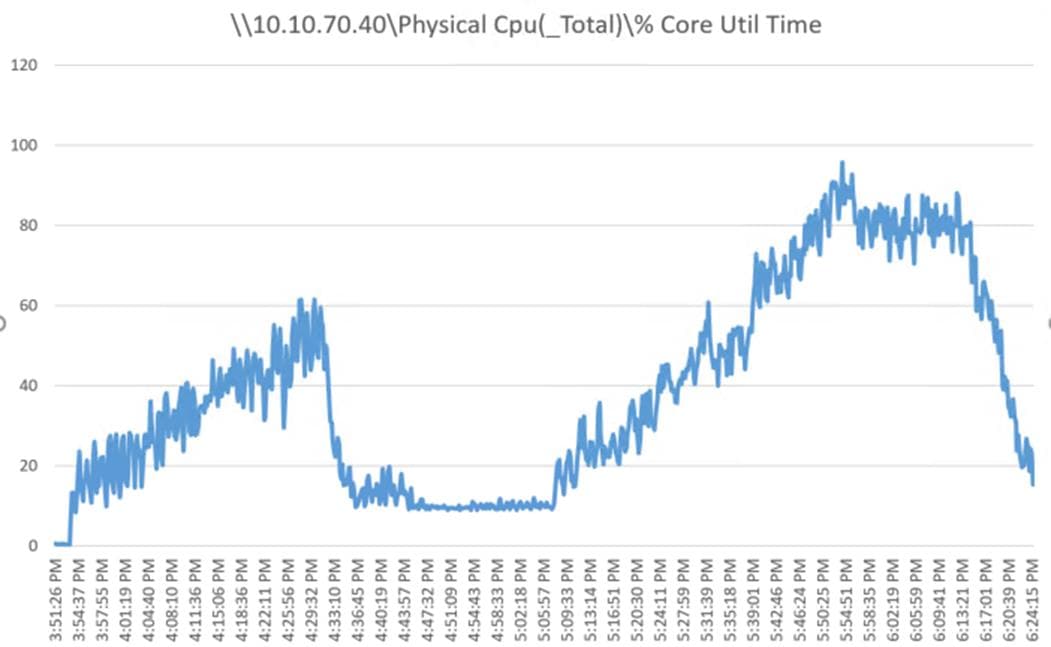
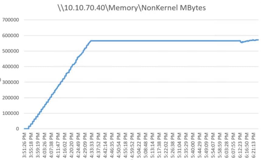
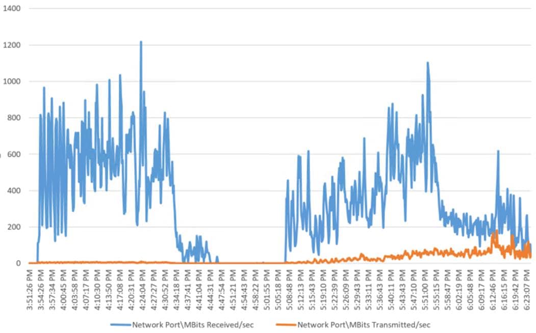
Single-Server Recommended Maximum Workload for HSD with 270 Users
The recommended maximum workload for a Cisco UCS B200 M5 blade server with dual Intel Xeon Gold 6140 processors, 768GB 2666MHz RAM is 270 Server 2016 Hosted Shared Desktops. Each dedicated blade server ran 9 Server 2016 Virtual Machines. Each virtual server was configured with 9 vCPUs and 24GB RAM.
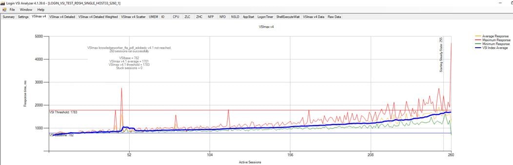
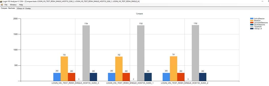
Performance data for the server running the workload is as follows:
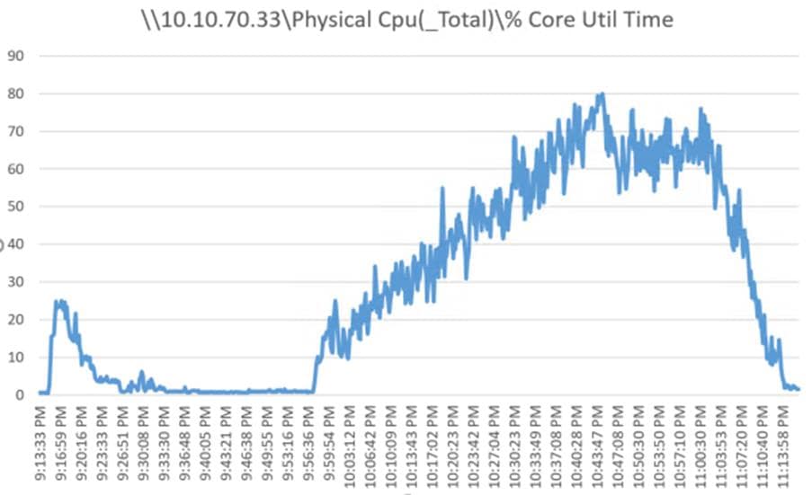
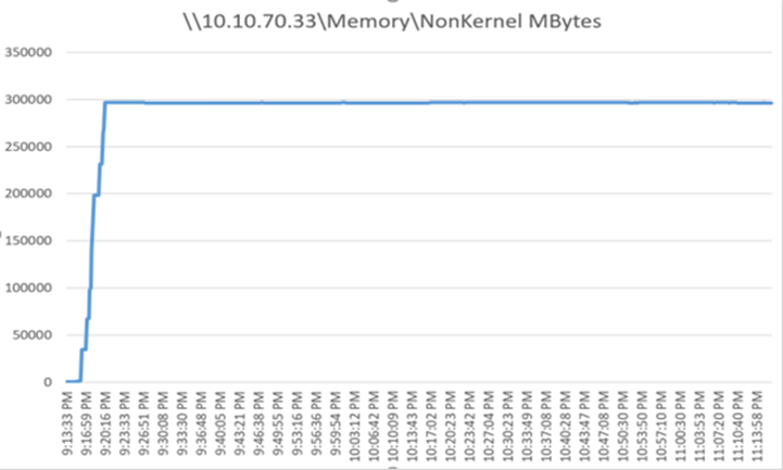
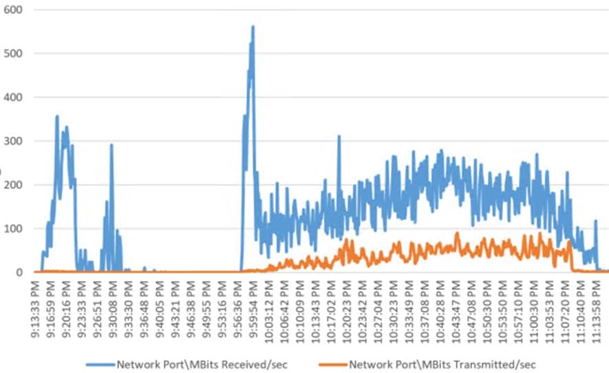
Full-scale Workload Testing
This section describes the key performance metrics that were captured on the Cisco UCS, during the full-scale testing. Full-scale testing was done with following Workloads using 30 Hosts for workload and 2 hosts for Infrastructure VMs:
1. VDI Persistent Desktop test- 5000 users
2. VDI Non-Persistent Desktop test- 5500 Users
3. HSD Test -6500 Sessions
To achieve the target, sessions were launched against each workload set at a time. As per the Cisco Test Protocol for VDI solutions, all sessions were launched within 48 minutes (using the official Knowledge Worker Workload in VSI Benchmark Mode) and all launched sessions became active within two minutes subsequent to the last logged in session.
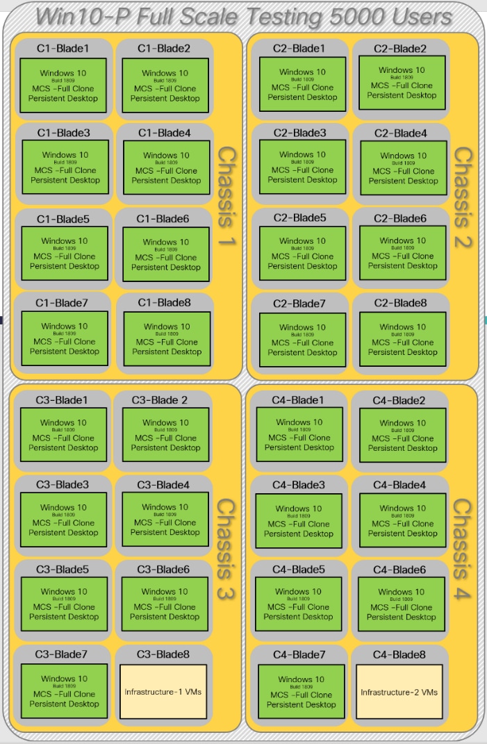
The configured system efficiently and effectively delivered the following results.
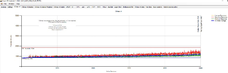
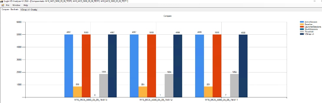
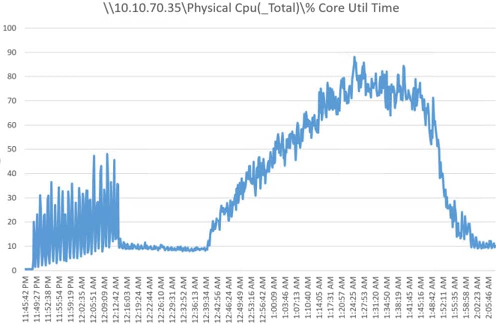
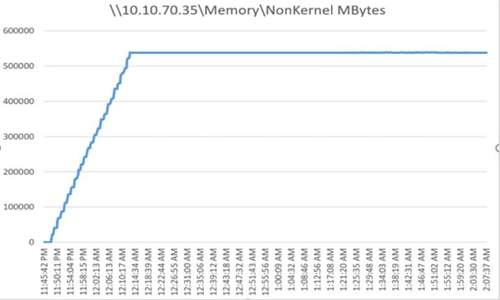
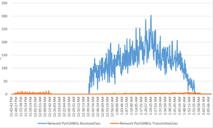
Pure Storage FlashArray//X70 R2 Storage System Graph for 5000 Users Persistent Desktop Workload Test
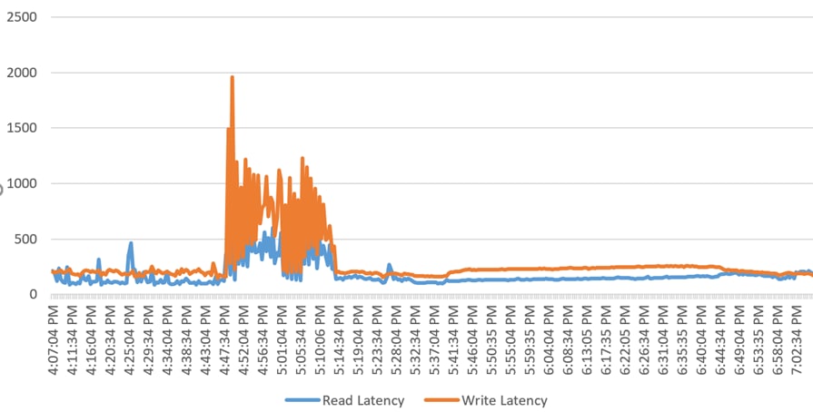
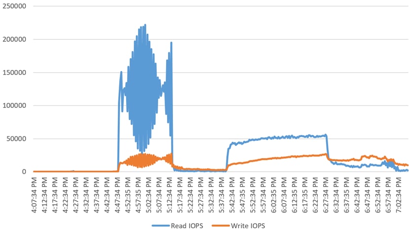
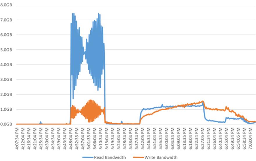
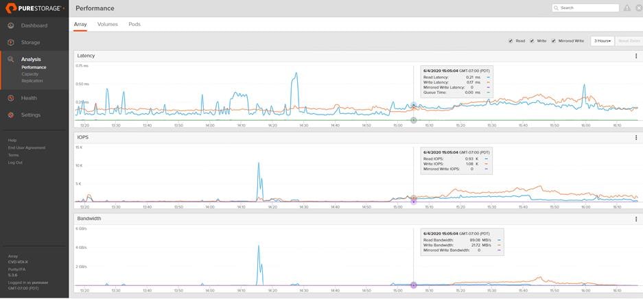
Full-scale VDI Non-Persistent Desktop Test - 5500 Users
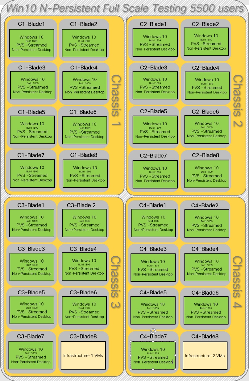
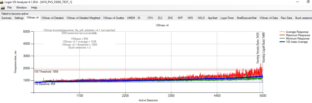
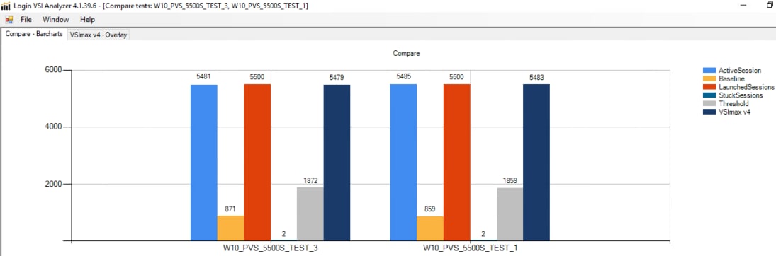
Figure 95 Full-scale | 5500 Users | VDI Non-Persistent VM Hosts | Host CPU Utilization
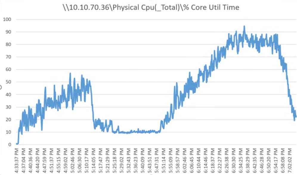
Figure 96 Full-scale | 5500 Mixed Users | HVD Non-Persistent Hosts | Host Memory Utilization
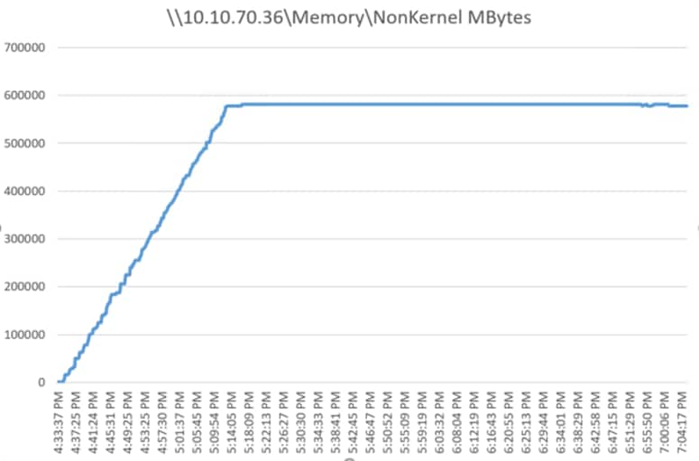
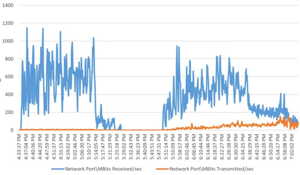
Pure Storage FlashArray//X70 R2 Storage System Graph for 5500 N-Persistent Workload Test
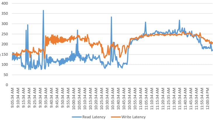
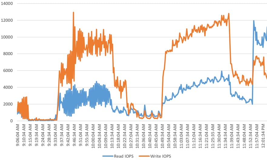
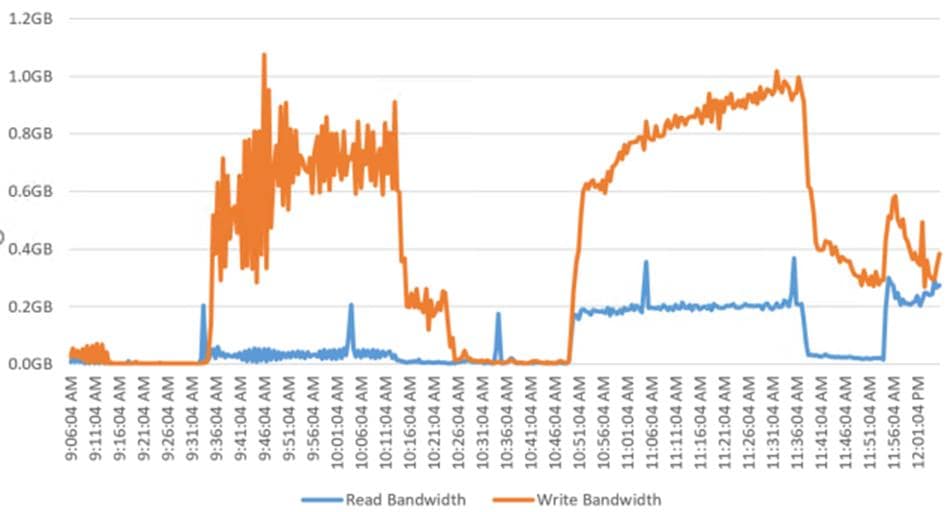
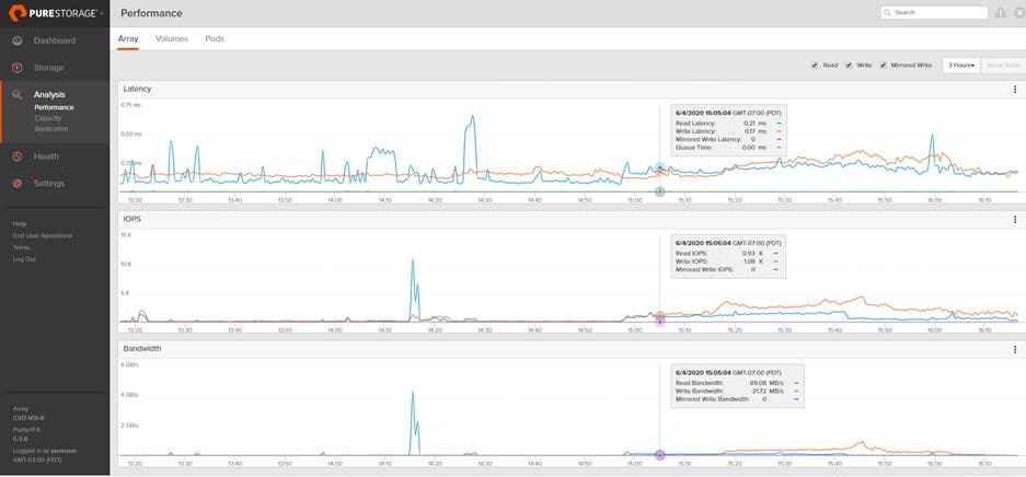
Full-scale HSD Test- 6500 Users
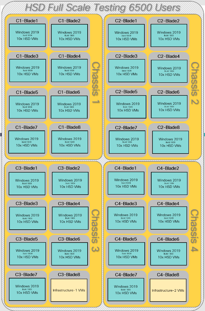
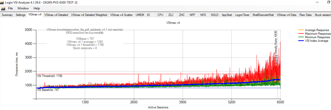
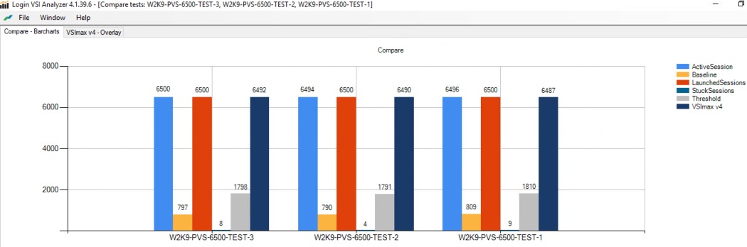
Figure 105 Full-scale | 6500 Users | Win 2019 HSD | Host CPU Utilization
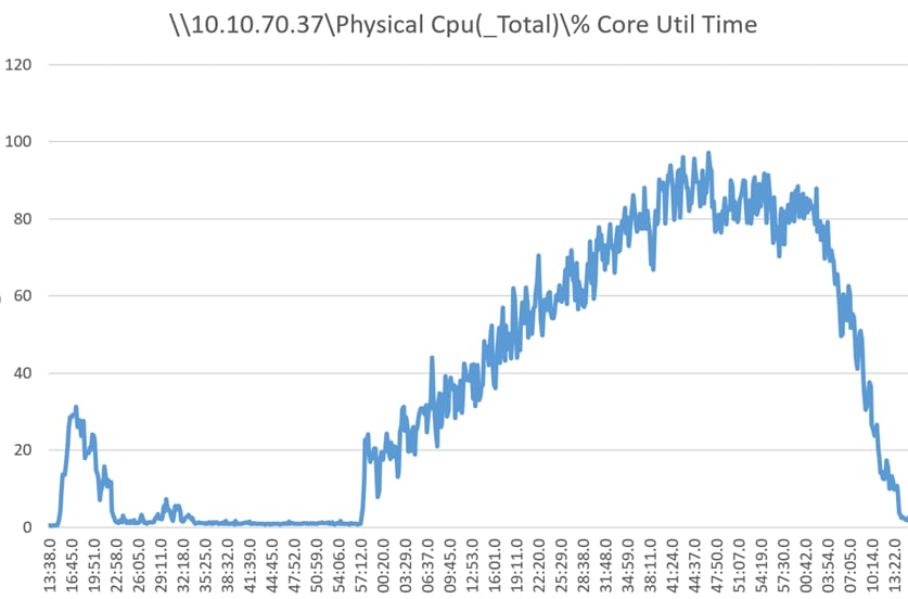
Figure 106 Full-scale | 6500 Users | Win 2019 HSD Hosts | Host Memory Utilization
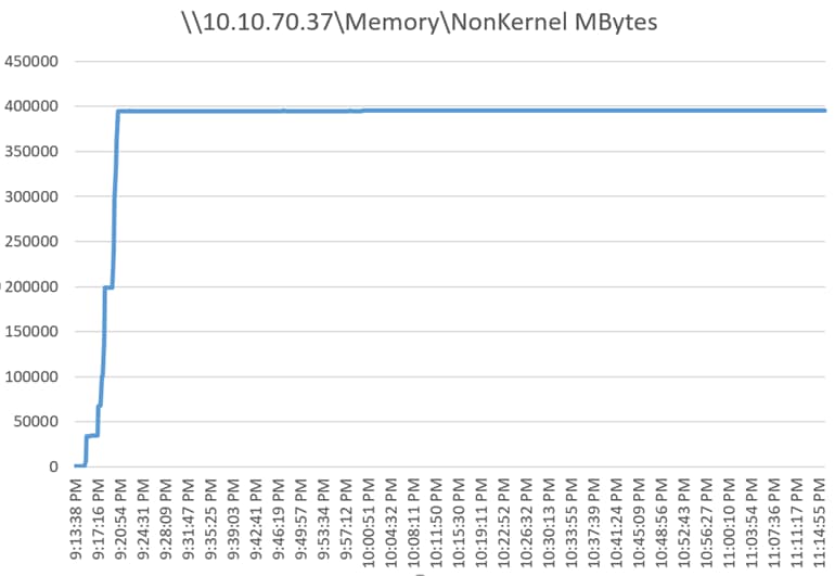
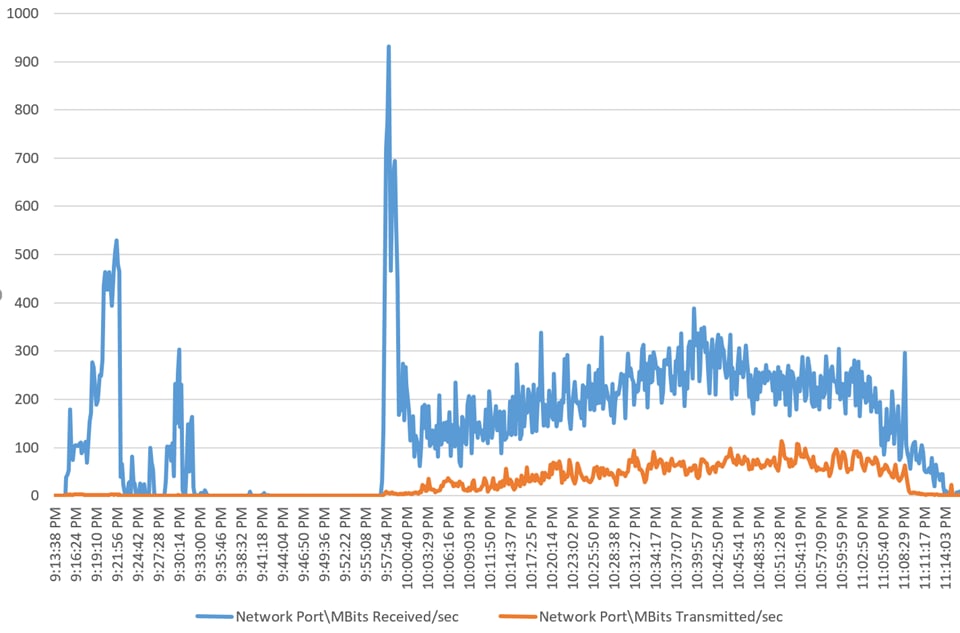
Pure Storage FlashArray//X70 R2 Storage System Graph for 6500 Users HSD Workload Test
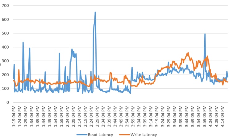
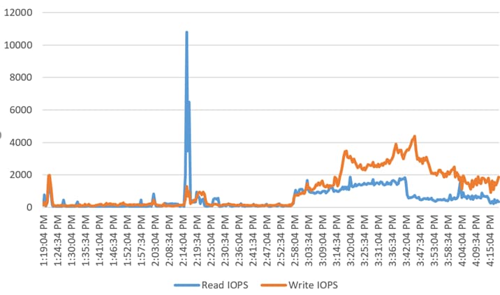
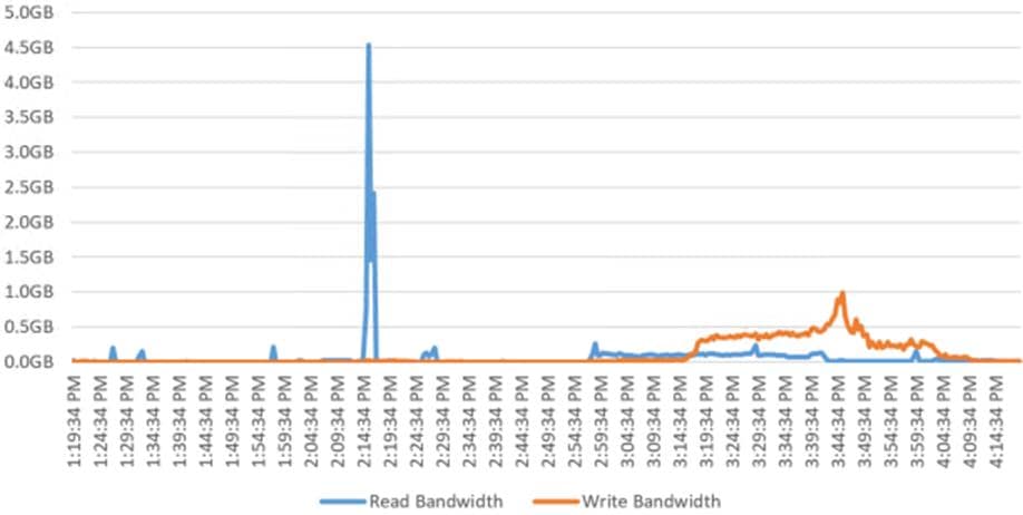

FlashStack delivers a platform for enterprise end-user computing deployments and cloud data centers using Cisco UCS Blade and Rack Servers, Cisco Fabric Interconnects, Cisco Nexus 9000 switches, Cisco MDS 9100 Fibre Channel switches, and Pure Storage FlashArray//X70 R2 Storage Array. FlashStack is designed and validated using compute, network and storage best practices and high availability to reduce deployment time, project risk and IT costs while maintaining scalability and flexibility for addressing a multitude of IT initiatives. This CVD validates the design, performance, management, scalability, and resilience that FlashStack provides to customers wishing to deploy enterprise-class VDI and HSD.
Get More Business Value with Services
Whether you are planning your next-generation environment, need specialized know-how for a major deployment, or want to get the most from your current storage, Cisco Advanced Services, Pure Storage FlashArray//X70 R2 storage and our certified partners can help. We collaborate with you to enhance your IT capabilities through a full portfolio of services that covers your IT lifecycle with:
· Strategy services to align IT with your business goals:
· Design services to architect your best storage environment
· Deploy and transition services to implement validated architectures and prepare your storage environment
· Operations services to deliver continuous operations while driving operational excellence and efficiency.
In addition, Cisco Advanced Services and Pure Storage Support provide in-depth knowledge transfer and education services that give you access to our global technical resources and intellectual property.
Shahed Jalal, Technical Marketing Engineer, Desktop Virtualization and Graphics Solutions, Cisco Systems, Inc.
Shahed Jalal is a member of the Cisco’s Computing Systems Product Group team focusing on design, testing, and solutions validation, technical content creation, and performance testing/benchmarking. He has years of experience in server and desktop virtualization. Shahed is a subject matter expert on Cisco Unified Computing System and Cisco Nexus Switching. He has worked at Cisco Systems, Inc. for more than 10 years in different technologies.
Acknowledgements
For their support and contribution to the design, validation, and creation of this Cisco Validated Design, we would like to acknowledge the following for their contribution and expertise that resulted in developing this document:
· Mike Brennan, Product Manager, Desktop Virtualization and Graphics Solutions, Cisco Systems, Inc.
· Vadim Lebedev, Technical Marketing Engineer, Cisco Systems, Inc.
· Kyle Grossmiller, Solutions Architect, Pure Storage, Inc.
· Craig Waters, Solutions Architect, Pure Storage, Inc.
This section provides links to additional information for each partner’s solution component of this document.
Cisco UCS B-Series Servers
· https://www.cisco.com/c/en/us/support/servers-unified-computing/ucs-b200-m5-blade-server/model.html
· https://www.cisco.com/c/en/us/td/docs/unified_computing/ucs/hw/blade-servers/B200M5.pdf
Cisco UCS Manager Configuration Guides
Cisco UCS Virtual Interface Cards
Cisco Nexus Switching References
· https://www.cisco.com/c/en/us/products/switches/nexus-93180yc-fx-switch/index.html
Cisco MDS 9000 Service Switch References
· http://www.cisco.com/c/en/us/products/storage-networking/product-listing.html
· https://www.cisco.com/c/en/us/products/collateral/storage-networking/mds-9132T 32-Gb-16g-multilayer-fabric-switch/datasheet-c78-731523.html
VMware References
· https://docs.vmware.com/en/VMware-vSphere/index.html
Citrix References
· https://docs.citrix.com/en-us/xenapp-and-xendesktop/7-15-ltsr.html
· https://support.citrix.com/article/CTX249912
· https://support.citrix.com/article/CTX216252?recommended
· https://support.citrix.com/article/CTX117374
Login VSI Documentation
· https://www.loginvsi.com/documentation/Main_Page
· https://www.loginvsi.com/documentation/Start_your_first_test
Pure Storage Reference Documents
· https://www.purestorage.com/content/dam/purestorage/pdf/datasheets/ps_ds_flasharray_03.pdf
· https://www.purestorage.com/products/evergreen-subscriptions.html
· https://www.purestorage.com/solutions/infrastructure/vdi.html
· https://www.purestorage.com/solutions/infrastructure/vdi-calculator.html
Ethernet Network Configuration
The following section provides a detailed procedure for configuring the Cisco Nexus 9000 Switches used in this study.
Cisco Nexus 93180YC-FX-A Configuration
!Command: show running-config
!Time: Fri May 17 19:22:52 2019
version 7.0(3)I7(2)
switchname AAD17-NX9K-A
class-map type network-qos class-fcoe
match qos-group 1
class-map type network-qos class-all-flood
match qos-group 2
class-map type network-qos class-ip-multicast
match qos-group 2
policy-map type network-qos jumbo
class type network-qos class-fcoe
mtu 2158
class type network-qos class-default
mtu 9216
install feature-set fcoe-npv
vdc AAD17-NX9K-A id 1
allow feature-set fcoe-npv
limit-resource vlan minimum 16 maximum 4094
limit-resource vrf minimum 2 maximum 4096
limit-resource port-channel minimum 0 maximum 511
limit-resource u4route-mem minimum 248 maximum 248
limit-resource u6route-mem minimum 96 maximum 96
limit-resource m4route-mem minimum 58 maximum 58
limit-resource m6route-mem minimum 8 maximum 8
feature-set fcoe-npv
feature telnet
cfs eth distribute
feature interface-vlan
feature hsrp
feature lacp
feature dhcp
feature vpc
feature lldp
no password strength-check
username admin password 5 $5$d3vc8gvD$hmf.YoRRPcqZ2dDGV2IaVKYZsPSPls8E9bpUzMciMZ
0 role network-admin
ip domain-lookup
system default switchport
class-map type qos match-all class-fcoe
policy-map type qos jumbo
class class-default
set qos-group 0
system qos
service-policy type network-qos jumbo
copp profile lenient
snmp-server user admin network-admin auth md5 0xc9a73d344387b8db2dc0f3fc624240ac
priv 0xc9a73d344387b8db2dc0f3fc624240ac localizedkey
rmon event 1 description FATAL(1) owner PMON@FATAL
rmon event 2 description CRITICAL(2) owner PMON@CRITICAL
rmon event 3 description ERROR(3) owner PMON@ERROR
rmon event 4 description WARNING(4) owner PMON@WARNING
rmon event 5 description INFORMATION(5) owner PMON@INFO
ntp server 10.10.70.2 use-vrf default
ntp peer 10.10.70.3 use-vrf default
ntp server 72.163.32.44 use-vrf management
ntp logging
ntp master 8
vlan 1,70-76
vlan 70
name InBand-Mgmt-SP
vlan 71
name Infra-Mgmt-SP
vlan 72
name VM-Network-SP
vlan 73
name vMotion-SP
vlan 74
name Storage_A-SP
vlan 75
name Storage_B-SP
vlan 76
name Launcher-SP
service dhcp
ip dhcp relay
ip dhcp relay information option
ipv6 dhcp relay
vrf context management
ip route 0.0.0.0/0 10.29.164.1
hardware access-list tcam region ing-racl 1536
hardware access-list tcam region ing-redirect 256
vpc domain 70
role priority 1000
peer-keepalive destination 10.29.164.234 source 10.29.164.233
interface Vlan1
no shutdown
ip address 10.29.164.241/24
interface Vlan70
no shutdown
ip address 10.10.70.2/24
hsrp version 2
hsrp 70
preempt
priority 110
ip 10.10.70.1
interface Vlan71
no shutdown
ip address 10.10.71.2/24
hsrp version 2
hsrp 71
preempt
priority 110
ip 10.10.71.1
interface Vlan72
no shutdown
ip address 10.72.0.2/19
hsrp version 2
hsrp 72
preempt
priority 110
ip 10.72.0.1
ip dhcp relay address 10.10.71.11
ip dhcp relay address 10.10.71.12
interface Vlan73
no shutdown
ip address 10.10.73.2/24
hsrp version 2
hsrp 73
preempt
priority 110
ip 10.10.73.1
interface Vlan74
no shutdown
ip address 10.10.74.2/24
hsrp version 2
hsrp 74
preempt
priority 110
ip 10.10.74.1
interface Vlan75
no shutdown
ip address 10.10.75.2/24
hsrp version 2
hsrp 75
preempt
priority 110
ip 10.10.75.1
interface Vlan76
no shutdown
ip address 10.10.76.2/23
hsrp version 2
hsrp 76
preempt
priority 110
ip 10.10.76.1
ip dhcp relay address 10.10.71.11
ip dhcp relay address 10.10.71.12
interface port-channel10
interface port-channel11
description FI-Uplink-D17
switchport mode trunk
switchport trunk allowed vlan 1,70-76
spanning-tree port type edge trunk
mtu 9216
service-policy type qos input jumbo
vpc 11
interface port-channel12
description FI-Uplink-D17
switchport mode trunk
switchport trunk allowed vlan 1,70-76
spanning-tree port type edge trunk
mtu 9216
service-policy type qos input jumbo
vpc 12
interface port-channel13
description FI-Uplink-D16
switchport mode trunk
switchport trunk allowed vlan 1,70-76
spanning-tree port type edge trunk
mtu 9216
service-policy type qos input jumbo
vpc 13
interface port-channel14
description FI-Uplink-D16
switchport mode trunk
switchport trunk allowed vlan 1,70-76
spanning-tree port type edge trunk
mtu 9216
service-policy type qos input jumbo
vpc 14
interface port-channel70
description vPC-PeerLink
switchport mode trunk
switchport trunk allowed vlan 1,70-76
spanning-tree port type network
service-policy type qos input jumbo
vpc peer-link
interface Ethernet1/1
interface Ethernet1/2
switchport mode trunk
switchport trunk allowed vlan 1,70-76
interface Ethernet1/3
switchport mode trunk
switchport trunk allowed vlan 1,70-76
mtu 9216
channel-group 13 mode active
interface Ethernet1/4
switchport mode trunk
switchport trunk allowed vlan 1,70-76
mtu 9216
channel-group 13 mode active
interface Ethernet1/5
switchport mode trunk
switchport trunk allowed vlan 1,70-76
mtu 9216
channel-group 14 mode active
interface Ethernet1/6
switchport mode trunk
switchport trunk allowed vlan 1,70-76
mtu 9216
channel-group 14 mode active
interface Ethernet1/7
interface Ethernet1/8
interface Ethernet1/9
interface Ethernet1/10
interface Ethernet1/11
interface Ethernet1/12
interface Ethernet1/13
interface Ethernet1/14
interface Ethernet1/15
interface Ethernet1/16
interface Ethernet1/17
interface Ethernet1/18
interface Ethernet1/19
interface Ethernet1/20
interface Ethernet1/21
interface Ethernet1/22
interface Ethernet1/23
interface Ethernet1/24
interface Ethernet1/25
interface Ethernet1/26
interface Ethernet1/27
interface Ethernet1/28
interface Ethernet1/29
interface Ethernet1/30
interface Ethernet1/31
interface Ethernet1/32
interface Ethernet1/33
interface Ethernet1/34
interface Ethernet1/35
interface Ethernet1/36
interface Ethernet1/37
interface Ethernet1/38
interface Ethernet1/39
interface Ethernet1/40
interface Ethernet1/41
interface Ethernet1/42
interface Ethernet1/43
interface Ethernet1/44
interface Ethernet1/45
interface Ethernet1/46
interface Ethernet1/47
interface Ethernet1/48
interface Ethernet1/49
interface Ethernet1/50
interface Ethernet1/51
switchport mode trunk
switchport trunk allowed vlan 1,70-76
mtu 9216
channel-group 11 mode active
interface Ethernet1/52
switchport mode trunk
switchport trunk allowed vlan 1,70-76
mtu 9216
channel-group 12 mode active
interface Ethernet1/53
switchport mode trunk
switchport trunk allowed vlan 1,70-76
channel-group 70 mode active
interface Ethernet1/54
switchport mode trunk
switchport trunk allowed vlan 1,70-76
channel-group 70 mode active
interface mgmt0
vrf member management
ip address 10.29.164.233/24
line console
line vty
boot nxos bootflash:/nxos.7.0.3.I7.2.bin
no system default switchport shutdown
Cisco Nexus 93180YC-FX-B Configuration
!Command: show running-config
!Time: Fri May 17 19:25:15 2019
version 7.0(3)I7(2)
switchname AAD17-NX9K-B
class-map type network-qos class-fcoe
match qos-group 1
class-map type network-qos class-all-flood
match qos-group 2
class-map type network-qos class-ip-multicast
match qos-group 2
policy-map type network-qos jumbo
class type network-qos class-fcoe
mtu 2158
class type network-qos class-default
mtu 9216
install feature-set fcoe-npv
vdc AAD17-NX9K-B id 1
allow feature-set fcoe-npv
limit-resource vlan minimum 16 maximum 4094
limit-resource vrf minimum 2 maximum 4096
limit-resource port-channel minimum 0 maximum 511
limit-resource u4route-mem minimum 248 maximum 248
limit-resource u6route-mem minimum 96 maximum 96
limit-resource m4route-mem minimum 58 maximum 58
limit-resource m6route-mem minimum 8 maximum 8
feature-set fcoe-npv
feature telnet
cfs eth distribute
feature interface-vlan
feature hsrp
feature lacp
feature dhcp
feature vpc
feature lldp
no password strength-check
username admin password 5 $5$/48.OHa8$g6pOMLIwrzqxJesMYoP5CNphujBksPPRjn4I3iFfOp
. role network-admin
ip domain-lookup
system default switchport
class-map type qos match-all class-fcoe
policy-map type qos jumbo
class class-default
set qos-group 0
system qos
service-policy type network-qos jumbo
copp profile lenient
snmp-server user admin network-admin auth md5 0x6d450e3d5a3927ddee1dadd30e5f616f
priv 0x6d450e3d5a3927ddee1dadd30e5f616f localizedkey
rmon event 1 description FATAL(1) owner PMON@FATAL
rmon event 2 description CRITICAL(2) owner PMON@CRITICAL
rmon event 3 description ERROR(3) owner PMON@ERROR
rmon event 4 description WARNING(4) owner PMON@WARNING
rmon event 5 description INFORMATION(5) owner PMON@INFO
ntp peer 10.10.70.2 use-vrf default
ntp server 10.10.70.3 use-vrf default
ntp server 72.163.32.44 use-vrf management
ntp logging
ntp master 8
vlan 1,70-76
vlan 70
name InBand-Mgmt-SP
vlan 71
name Infra-Mgmt-SP
vlan 72
name VM-Network-SP
vlan 73
name vMotion-SP
vlan 74
name Storage_A-SP
vlan 75
name Storage_B-SP
vlan 76
name Launcher-SP
service dhcp
ip dhcp relay
ip dhcp relay information option
ipv6 dhcp relay
vrf context management
ip route 0.0.0.0/0 10.29.164.1
hardware access-list tcam region ing-racl 1536
hardware access-list tcam region ing-redirect 256
vpc domain 70
role priority 2000
peer-keepalive destination 10.29.164.233 source 10.29.164.234
interface Vlan1
no shutdown
ip address 10.29.164.240/24
interface Vlan70
no shutdown
ip address 10.10.70.3/24
hsrp version 2
hsrp 70
preempt
priority 110
ip 10.10.70.1
interface Vlan71
no shutdown
ip address 10.10.71.3/24
hsrp version 2
hsrp 71
preempt
priority 110
ip 10.10.71.1
interface Vlan72
no shutdown
ip address 10.72.0.2/19
hsrp version 2
hsrp 72
preempt
priority 110
ip 10.72.0.1
ip dhcp relay address 10.10.71.11
ip dhcp relay address 10.10.71.12
interface Vlan73
no shutdown
ip address 10.10.73.3/24
hsrp version 2
hsrp 73
preempt
priority 110
ip 10.10.73.1
interface Vlan74
no shutdown
ip address 10.10.74.3/24
hsrp version 2
hsrp 74
preempt
priority 110
ip 10.10.74.1
interface Vlan75
no shutdown
ip address 10.10.75.3/24
hsrp version 2
hsrp 75
preempt
priority 110
ip 10.10.75.1
interface Vlan76
no shutdown
ip address 10.10.76.3/23
hsrp version 2
hsrp 76
preempt
priority 110
ip 10.10.76.1
ip dhcp relay address 10.10.71.11
ip dhcp relay address 10.10.71.12
interface port-channel10
interface port-channel11
description FI-Uplink-D17
switchport mode trunk
switchport trunk allowed vlan 1,70-76
spanning-tree port type edge trunk
mtu 9216
service-policy type qos input jumbo
vpc 11
interface port-channel12
description FI-Uplink-D17
switchport mode trunk
switchport trunk allowed vlan 1,70-76
spanning-tree port type edge trunk
mtu 9216
service-policy type qos input jumbo
vpc 12
interface port-channel13
description FI-Uplink-D16
switchport mode trunk
switchport trunk allowed vlan 1,70-76
spanning-tree port type edge trunk
mtu 9216
service-policy type qos input jumbo
vpc 13
interface port-channel14
description FI-Uplink-D16
switchport mode trunk
switchport trunk allowed vlan 1,70-76
spanning-tree port type edge trunk
mtu 9216
service-policy type qos input jumbo
vpc 14
interface port-channel70
description vPC-PeerLink
switchport mode trunk
switchport trunk allowed vlan 1,70-76
spanning-tree port type network
service-policy type qos input jumbo
vpc peer-link
interface Ethernet1/1
switchport access vlan 70
speed 1000
interface Ethernet1/2
switchport mode trunk
switchport trunk allowed vlan 1,70-76
interface Ethernet1/3
switchport mode trunk
switchport trunk allowed vlan 1,70-76
mtu 9216
channel-group 13 mode active
interface Ethernet1/4
switchport mode trunk
switchport trunk allowed vlan 1,70-76
mtu 9216
channel-group 13 mode active
interface Ethernet1/5
switchport mode trunk
switchport trunk allowed vlan 1,70-76
mtu 9216
channel-group 14 mode active
interface Ethernet1/6
switchport mode trunk
switchport trunk allowed vlan 1,70-76
mtu 9216
channel-group 14 mode active
interface Ethernet1/7
interface Ethernet1/8
interface Ethernet1/9
interface Ethernet1/10
interface Ethernet1/11
interface Ethernet1/12
interface Ethernet1/13
interface Ethernet1/14
interface Ethernet1/15
interface Ethernet1/16
interface Ethernet1/17
interface Ethernet1/18
interface Ethernet1/19
interface Ethernet1/20
interface Ethernet1/21
interface Ethernet1/22
interface Ethernet1/23
interface Ethernet1/24
interface Ethernet1/25
interface Ethernet1/26
interface Ethernet1/27
interface Ethernet1/28
interface Ethernet1/29
interface Ethernet1/30
interface Ethernet1/31
interface Ethernet1/32
interface Ethernet1/33
interface Ethernet1/34
interface Ethernet1/35
interface Ethernet1/36
interface Ethernet1/37
interface Ethernet1/38
interface Ethernet1/39
interface Ethernet1/40
interface Ethernet1/41
interface Ethernet1/42
interface Ethernet1/43
interface Ethernet1/44
interface Ethernet1/45
interface Ethernet1/46
interface Ethernet1/47
interface Ethernet1/48
interface Ethernet1/49
interface Ethernet1/50
interface Ethernet1/51
switchport mode trunk
switchport trunk allowed vlan 1,70-76
mtu 9216
channel-group 11 mode active
interface Ethernet1/52
switchport mode trunk
switchport trunk allowed vlan 1,70-76
mtu 9216
channel-group 12 mode active
interface Ethernet1/53
switchport mode trunk
switchport trunk allowed vlan 1,70-76
channel-group 70 mode active
interface Ethernet1/54
switchport mode trunk
switchport trunk allowed vlan 1,70-76
channel-group 70 mode active
interface mgmt0
vrf member management
ip address 10.29.164.234/24
line console
line vty
boot nxos bootflash:/nxos.7.0.3.I7.2.bin
Cisco MDS 9132T Fibre Channel Network Configuration
The following section provides a detailed procedure for configuring the Cisco MDS 9100 Switches used in this study.
Cisco MDS 9132T 32-Gb-A Configuration
!Command: show running-config
!Running configuration last done at: Wed Mar 20 04:02:24 2019
!Time: Fri May 17 20:50:47 2019
version 8.3(1)
power redundancy-mode redundant
feature npiv
feature fport-channel-trunk
role name default-role
description This is a system defined role and applies to all users.
rule 5 permit show feature environment
rule 4 permit show feature hardware
rule 3 permit show feature module
rule 2 permit show feature snmp
rule 1 permit show feature system
no password strength-check
username admin password 5 $5$kAIE4kXd$3rDLwb/BjpcAzi.KtGNzxmEWijVraamDzl/xL61as.4 role network-admin
ip domain-lookup
ip name-server 10.10.61.30
ip host ADD16-MDS-A 10.29.164.238
aaa group server radius radius
snmp-server user admin network-admin auth md5 0x3404c40cc872c0c3391c85d64ecdc64e priv 0xf61ac3a6f9d55d71960b617393b98ebe localizedkey
rmon event 1 log trap public description FATAL(1) owner PMON@FATAL
rmon event 2 log trap public description CRITICAL(2) owner PMON@CRITICAL
rmon event 3 log trap public description ERROR(3) owner PMON@ERROR
rmon event 4 log trap public description WARNING(4) owner PMON@WARNING
rmon event 5 log trap public description INFORMATION(5) owner PMON@INFO
ntp server 10.81.254.131
ntp server 10.81.254.202
vsan database
vsan 100 name "FlashStack-VCC-CVD-Fabric-A"
vsan 400 name "FlexPod-A"
device-alias database
device-alias name C480M5-P0 pwwn 21:00:00:0e:1e:10:a2:c0
device-alias name VDI-1-HBA1 pwwn 20:00:00:25:b5:3a:00:3f
device-alias name VDI-2-HBA1 pwwn 20:00:00:25:b5:3a:00:0f
device-alias name VDI-3-HBA1 pwwn 20:00:00:25:b5:3a:00:1f
device-alias name VDI-4-HBA1 pwwn 20:00:00:25:b5:3a:00:4e
device-alias name VDI-5-HBA1 pwwn 20:00:00:25:b5:3a:00:2e
device-alias name VDI-6-HBA1 pwwn 20:00:00:25:b5:3a:00:3e
device-alias name VDI-7-HBA1 pwwn 20:00:00:25:b5:3a:00:0e
device-alias name VDI-9-HBA1 pwwn 20:00:00:25:b5:3a:00:4d
device-alias name CS700-FC1-1 pwwn 56:c9:ce:90:0d:e8:24:02
device-alias name CS700-FC2-1 pwwn 56:c9:ce:90:0d:e8:24:06
device-alias name VDI-10-HBA1 pwwn 20:00:00:25:b5:3a:00:2d
device-alias name VDI-11-HBA1 pwwn 20:00:00:25:b5:3a:00:3d
device-alias name VDI-12-HBA1 pwwn 20:00:00:25:b5:3a:00:0d
device-alias name VDI-13-HBA1 pwwn 20:00:00:25:b5:3a:00:1d
device-alias name VDI-14-HBA1 pwwn 20:00:00:25:b5:3a:00:4c
device-alias name VDI-15-HBA1 pwwn 20:00:00:25:b5:3a:00:2c
device-alias name VDI-17-HBA1 pwwn 20:00:00:25:b5:3a:00:0c
device-alias name VDI-18-HBA1 pwwn 20:00:00:25:b5:3a:00:1c
device-alias name VDI-19-HBA1 pwwn 20:00:00:25:b5:3a:00:4b
device-alias name VDI-20-HBA1 pwwn 20:00:00:25:b5:3a:00:2b
device-alias name VDI-21-HBA1 pwwn 20:00:00:25:b5:3a:00:3b
device-alias name VDI-22-HBA1 pwwn 20:00:00:25:b5:3a:00:0b
device-alias name VDI-23-HBA1 pwwn 20:00:00:25:b5:3a:00:1b
device-alias name VDI-24-HBA1 pwwn 20:00:00:25:b5:3a:00:4a
device-alias name VDI-25-HBA1 pwwn 20:00:00:25:b5:3a:00:2a
device-alias name VDI-26-HBA1 pwwn 20:00:00:25:b5:3a:00:3a
device-alias name VDI-27-HBA1 pwwn 20:00:00:25:b5:3a:00:0a
device-alias name VDI-28-HBA1 pwwn 20:00:00:25:b5:3a:00:1a
device-alias name VDI-29-HBA1 pwwn 20:00:00:25:b5:3a:00:49
device-alias name VDI-30-HBA1 pwwn 20:00:00:25:b5:3a:00:39
device-alias name VDI-31-HBA1 pwwn 20:00:00:25:b5:3a:00:1e
device-alias name VDI-32-HBA1 pwwn 20:00:00:25:b5:3a:00:3c
device-alias name X70-CT0-FC0 pwwn 52:4a:93:75:dd:91:0a:00
device-alias name X70-CT0-FC1 pwwn 52:4a:93:75:dd:91:0a:01
device-alias name X70-CT0-FC8 pwwn 52:4a:93:75:dd:91:0a:06
device-alias name X70-CT1-FC0 pwwn 52:4a:93:75:dd:91:0a:10
device-alias name X70-CT1-FC1 pwwn 52:4a:93:75:dd:91:0a:11
device-alias name X70-CT1-FC8 pwwn 52:4a:93:75:dd:91:0a:16
device-alias name Infra01-8-HBA1 pwwn 20:00:00:25:b5:3a:00:4f
device-alias name Infra02-16-HBA1 pwwn 20:00:00:25:b5:3a:00:2f
device-alias name VCC-Infra01-HBA0 pwwn 20:00:00:25:b5:aa:17:1e
device-alias name VCC-Infra01-HBA2 pwwn 20:00:00:25:b5:aa:17:1f
device-alias name VCC-Infra02-HBA0 pwwn 20:00:00:25:b5:aa:17:3e
device-alias name VCC-Infra02-HBA2 pwwn 20:00:00:25:b5:aa:17:3f
device-alias name VDI-Host01-HBA0 pwwn 20:00:00:25:b5:aa:17:00
device-alias name VDI-Host01-HBA2 pwwn 20:00:00:25:b5:aa:17:01
device-alias name VDI-Host02-HBA0 pwwn 20:00:00:25:b5:aa:17:02
device-alias name VDI-Host02-HBA2 pwwn 20:00:00:25:b5:aa:17:03
device-alias name VDI-Host03-HBA0 pwwn 20:00:00:25:b5:aa:17:04
device-alias name VDI-Host03-HBA2 pwwn 20:00:00:25:b5:aa:17:05
device-alias name VDI-Host04-HBA0 pwwn 20:00:00:25:b5:aa:17:06
device-alias name VDI-Host04-HBA2 pwwn 20:00:00:25:b5:aa:17:07
device-alias name VDI-Host05-HBA0 pwwn 20:00:00:25:b5:aa:17:08
device-alias name VDI-Host05-HBA2 pwwn 20:00:00:25:b5:aa:17:09
device-alias name VDI-Host06-HBA0 pwwn 20:00:00:25:b5:aa:17:0a
device-alias name VDI-Host06-HBA2 pwwn 20:00:00:25:b5:aa:17:0b
device-alias name VDI-Host07-HBA0 pwwn 20:00:00:25:b5:aa:17:0c
device-alias name VDI-Host07-HBA2 pwwn 20:00:00:25:b5:aa:17:0d
device-alias name VDI-Host08-HBA0 pwwn 20:00:00:25:b5:aa:17:0e
device-alias name VDI-Host08-HBA2 pwwn 20:00:00:25:b5:aa:17:0f
device-alias name VDI-Host09-HBA0 pwwn 20:00:00:25:b5:aa:17:10
device-alias name VDI-Host09-HBA2 pwwn 20:00:00:25:b5:aa:17:11
device-alias name VDI-Host10-HBA0 pwwn 20:00:00:25:b5:aa:17:12
device-alias name VDI-Host10-HBA2 pwwn 20:00:00:25:b5:aa:17:13
device-alias name VDI-Host11-HBA0 pwwn 20:00:00:25:b5:aa:17:14
device-alias name VDI-Host11-HBA2 pwwn 20:00:00:25:b5:aa:17:15
device-alias name VDI-Host12-HBA0 pwwn 20:00:00:25:b5:aa:17:16
device-alias name VDI-Host12-HBA2 pwwn 20:00:00:25:b5:aa:17:17
device-alias name VDI-Host13-HBA0 pwwn 20:00:00:25:b5:aa:17:18
device-alias name VDI-Host13-HBA2 pwwn 20:00:00:25:b5:aa:17:19
device-alias name VDI-Host14-HBA0 pwwn 20:00:00:25:b5:aa:17:1a
device-alias name VDI-Host14-HBA2 pwwn 20:00:00:25:b5:aa:17:1b
device-alias name VDI-Host15-HBA0 pwwn 20:00:00:25:b5:aa:17:1c
device-alias name VDI-Host15-HBA2 pwwn 20:00:00:25:b5:aa:17:1d
device-alias name VDI-Host16-HBA0 pwwn 20:00:00:25:b5:aa:17:20
device-alias name VDI-Host16-HBA2 pwwn 20:00:00:25:b5:aa:17:21
device-alias name VDI-Host17-HBA0 pwwn 20:00:00:25:b5:aa:17:22
device-alias name VDI-Host17-HBA2 pwwn 20:00:00:25:b5:aa:17:23
device-alias name VDI-Host18-HBA0 pwwn 20:00:00:25:b5:aa:17:24
device-alias name VDI-Host18-HBA2 pwwn 20:00:00:25:b5:aa:17:25
device-alias name VDI-Host19-HBA0 pwwn 20:00:00:25:b5:aa:17:26
device-alias name VDI-Host19-HBA2 pwwn 20:00:00:25:b5:aa:17:27
device-alias name VDI-Host20-HBA0 pwwn 20:00:00:25:b5:aa:17:28
device-alias name VDI-Host20-HBA2 pwwn 20:00:00:25:b5:aa:17:29
device-alias name VDI-Host21-HBA0 pwwn 20:00:00:25:b5:aa:17:2a
device-alias name VDI-Host21-HBA2 pwwn 20:00:00:25:b5:aa:17:2b
device-alias name VDI-Host22-HBA0 pwwn 20:00:00:25:b5:aa:17:2c
device-alias name VDI-Host22-HBA2 pwwn 20:00:00:25:b5:aa:17:2d
device-alias name VDI-Host23-HBA0 pwwn 20:00:00:25:b5:aa:17:2e
device-alias name VDI-Host23-HBA2 pwwn 20:00:00:25:b5:aa:17:2f
device-alias name VDI-Host24-HBA0 pwwn 20:00:00:25:b5:aa:17:30
device-alias name VDI-Host24-HBA2 pwwn 20:00:00:25:b5:aa:17:31
device-alias name VDI-Host25-HBA0 pwwn 20:00:00:25:b5:aa:17:32
device-alias name VDI-Host25-HBA2 pwwn 20:00:00:25:b5:aa:17:33
device-alias name VDI-Host26-HBA0 pwwn 20:00:00:25:b5:aa:17:34
device-alias name VDI-Host26-HBA2 pwwn 20:00:00:25:b5:aa:17:35
device-alias name VDI-Host27-HBA0 pwwn 20:00:00:25:b5:aa:17:36
device-alias name VDI-Host27-HBA2 pwwn 20:00:00:25:b5:aa:17:37
device-alias name VDI-Host28-HBA0 pwwn 20:00:00:25:b5:aa:17:38
device-alias name VDI-Host28-HBA2 pwwn 20:00:00:25:b5:aa:17:39
device-alias name VDI-Host29-HBA0 pwwn 20:00:00:25:b5:aa:17:3a
device-alias name VDI-Host29-HBA2 pwwn 20:00:00:25:b5:aa:17:3b
device-alias name VDI-Host30-HBA0 pwwn 20:00:00:25:b5:aa:17:3c
device-alias name VDI-Host30-HBA2 pwwn 20:00:00:25:b5:aa:17:3d
device-alias commit
fcdomain fcid database
vsan 100 wwn 20:03:00:de:fb:92:8d:00 fcid 0x300000 dynamic
vsan 100 wwn 52:4a:93:75:dd:91:0a:01 fcid 0x300020 dynamic
! [X70-CT0-FC1]
vsan 100 wwn 52:4a:93:75:dd:91:0a:17 fcid 0x300040 dynamic
vsan 100 wwn 52:4a:93:75:dd:91:0a:06 fcid 0x300041 dynamic
! [X70-CT0-FC8]
vsan 100 wwn 52:4a:93:75:dd:91:0a:07 fcid 0x300042 dynamic
vsan 100 wwn 52:4a:93:75:dd:91:0a:16 fcid 0x300043 dynamic
! [X70-CT1-FC8]
vsan 100 wwn 20:00:00:25:b5:aa:17:3e fcid 0x300060 dynamic
! [VCC-Infra02-HBA0]
vsan 100 wwn 20:00:00:25:b5:aa:17:07 fcid 0x300061 dynamic
! [VDI-Host04-HBA2]
vsan 100 wwn 20:00:00:25:b5:aa:17:06 fcid 0x300062 dynamic
! [VDI-Host04-HBA0]
vsan 100 wwn 20:00:00:25:b5:aa:17:3a fcid 0x300063 dynamic
! [VDI-Host29-HBA0]
vsan 100 wwn 20:00:00:25:b5:aa:17:29 fcid 0x300064 dynamic
! [VDI-Host20-HBA2]
vsan 100 wwn 20:00:00:25:b5:aa:17:13 fcid 0x300065 dynamic
! [VDI-Host10-HBA2]
vsan 100 wwn 20:00:00:25:b5:aa:17:1c fcid 0x300066 dynamic
! [VDI-Host15-HBA0]
vsan 100 wwn 20:00:00:25:b5:aa:17:32 fcid 0x300067 dynamic
! [VDI-Host25-HBA0]
vsan 100 wwn 20:00:00:25:b5:aa:17:17 fcid 0x300068 dynamic
! [VDI-Host12-HBA2]
vsan 100 wwn 20:00:00:25:b5:aa:17:2e fcid 0x300069 dynamic
! [VDI-Host23-HBA0]
vsan 100 wwn 20:00:00:25:b5:aa:17:1f fcid 0x30006a dynamic
! [VCC-Infra01-HBA2]
vsan 100 wwn 20:00:00:25:b5:aa:17:1b fcid 0x30006b dynamic
! [VDI-Host14-HBA2]
vsan 100 wwn 20:00:00:25:b5:aa:17:1a fcid 0x30006c dynamic
! [VDI-Host14-HBA0]
vsan 100 wwn 20:00:00:25:b5:aa:17:0a fcid 0x30006d dynamic
! [VDI-Host06-HBA0]
vsan 100 wwn 20:00:00:25:b5:aa:17:34 fcid 0x30006e dynamic
! [VDI-Host26-HBA0]
vsan 100 wwn 20:00:00:25:b5:aa:17:19 fcid 0x30006f dynamic
! [VDI-Host13-HBA2]
vsan 100 wwn 20:00:00:25:b5:aa:17:36 fcid 0x300070 dynamic
! [VDI-Host27-HBA0]
vsan 100 wwn 20:00:00:25:b5:aa:17:01 fcid 0x300071 dynamic
! [VDI-Host01-HBA2]
vsan 100 wwn 20:00:00:25:b5:aa:17:12 fcid 0x300072 dynamic
! [VDI-Host10-HBA0]
vsan 100 wwn 20:00:00:25:b5:aa:17:16 fcid 0x300073 dynamic
! [VDI-Host12-HBA0]
vsan 100 wwn 20:00:00:25:b5:aa:17:2b fcid 0x300074 dynamic
! [VDI-Host21-HBA2]
vsan 100 wwn 20:00:00:25:b5:aa:17:25 fcid 0x300075 dynamic
! [VDI-Host18-HBA2]
vsan 100 wwn 20:00:00:25:b5:aa:17:27 fcid 0x300076 dynamic
! [VDI-Host19-HBA2]
vsan 100 wwn 20:00:00:25:b5:aa:17:3d fcid 0x300077 dynamic
! [VDI-Host30-HBA2]
vsan 100 wwn 20:00:00:25:b5:aa:17:15 fcid 0x300078 dynamic
! [VDI-Host11-HBA2]
vsan 100 wwn 20:00:00:25:b5:aa:17:38 fcid 0x300079 dynamic
! [VDI-Host28-HBA0]
vsan 100 wwn 20:00:00:25:b5:aa:17:23 fcid 0x30007a dynamic
! [VDI-Host17-HBA2]
vsan 100 wwn 20:00:00:25:b5:aa:17:00 fcid 0x30007b dynamic
! [VDI-Host01-HBA0]
vsan 100 wwn 20:00:00:25:b5:aa:17:04 fcid 0x30007c dynamic
! [VDI-Host03-HBA0]
vsan 100 wwn 20:00:00:25:b5:aa:17:03 fcid 0x30007d dynamic
! [VDI-Host02-HBA2]
vsan 100 wwn 20:00:00:25:b5:aa:17:0f fcid 0x30007e dynamic
! [VDI-Host08-HBA2]
vsan 100 wwn 20:00:00:25:b5:aa:17:1d fcid 0x30007f dynamic
! [VDI-Host15-HBA2]
vsan 100 wwn 20:00:00:25:b5:aa:17:31 fcid 0x300080 dynamic
! [VDI-Host24-HBA2]
vsan 100 wwn 20:00:00:25:b5:aa:17:30 fcid 0x300081 dynamic
! [VDI-Host24-HBA0]
vsan 100 wwn 20:00:00:25:b5:aa:17:02 fcid 0x300082 dynamic
! [VDI-Host02-HBA0]
vsan 100 wwn 20:00:00:25:b5:aa:17:08 fcid 0x300083 dynamic
! [VDI-Host05-HBA0]
vsan 100 wwn 20:00:00:25:b5:aa:17:26 fcid 0x300084 dynamic
! [VDI-Host19-HBA0]
vsan 100 wwn 20:00:00:25:b5:aa:17:22 fcid 0x300085 dynamic
! [VDI-Host17-HBA0]
vsan 100 wwn 20:00:00:25:b5:aa:17:2c fcid 0x300086 dynamic
! [VDI-Host22-HBA0]
vsan 100 wwn 20:00:00:25:b5:aa:17:33 fcid 0x300087 dynamic
! [VDI-Host25-HBA2]
vsan 100 wwn 20:00:00:25:b5:aa:17:21 fcid 0x300088 dynamic
! [VDI-Host16-HBA2]
vsan 100 wwn 20:00:00:25:b5:aa:17:2d fcid 0x300089 dynamic
! [VDI-Host22-HBA2]
vsan 100 wwn 20:00:00:25:b5:aa:17:24 fcid 0x30008a dynamic
! [VDI-Host18-HBA0]
vsan 100 wwn 20:00:00:25:b5:aa:17:3f fcid 0x30008b dynamic
! [VCC-Infra02-HBA2]
vsan 100 wwn 20:00:00:25:b5:aa:17:39 fcid 0x30008c dynamic
! [VDI-Host28-HBA2]
vsan 100 wwn 20:00:00:25:b5:aa:17:3c fcid 0x30008d dynamic
! [VDI-Host30-HBA0]
vsan 100 wwn 20:00:00:25:b5:aa:17:14 fcid 0x30008e dynamic
! [VDI-Host11-HBA0]
vsan 100 wwn 20:00:00:25:b5:aa:17:11 fcid 0x30008f dynamic
! [VDI-Host09-HBA2]
vsan 100 wwn 20:00:00:25:b5:aa:17:10 fcid 0x300090 dynamic
! [VDI-Host09-HBA0]
vsan 100 wwn 20:00:00:25:b5:aa:17:05 fcid 0x300091 dynamic
! [VDI-Host03-HBA2]
vsan 100 wwn 20:00:00:25:b5:aa:17:0e fcid 0x300092 dynamic
! [VDI-Host08-HBA0]
vsan 100 wwn 20:00:00:25:b5:aa:17:0d fcid 0x300093 dynamic
! [VDI-Host07-HBA2]
vsan 100 wwn 20:00:00:25:b5:aa:17:0c fcid 0x300094 dynamic
! [VDI-Host07-HBA0]
vsan 100 wwn 20:00:00:25:b5:aa:17:1e fcid 0x300095 dynamic
! [VCC-Infra01-HBA0]
vsan 100 wwn 20:00:00:25:b5:aa:17:0b fcid 0x300096 dynamic
! [VDI-Host06-HBA2]
vsan 100 wwn 20:00:00:25:b5:aa:17:28 fcid 0x300097 dynamic
! [VDI-Host20-HBA0]
vsan 100 wwn 20:00:00:25:b5:aa:17:37 fcid 0x300098 dynamic
! [VDI-Host27-HBA2]
vsan 100 wwn 20:00:00:25:b5:aa:17:3b fcid 0x300099 dynamic
! [VDI-Host29-HBA2]
vsan 100 wwn 20:00:00:25:b5:aa:17:09 fcid 0x30009a dynamic
! [VDI-Host05-HBA2]
vsan 100 wwn 20:00:00:25:b5:aa:17:2a fcid 0x30009b dynamic
! [VDI-Host21-HBA0]
vsan 100 wwn 20:00:00:25:b5:aa:17:2f fcid 0x30009c dynamic
! [VDI-Host23-HBA2]
vsan 100 wwn 20:00:00:25:b5:aa:17:20 fcid 0x30009d dynamic
! [VDI-Host16-HBA0]
vsan 100 wwn 20:00:00:25:b5:aa:17:35 fcid 0x30009e dynamic
! [VDI-Host26-HBA2]
vsan 100 wwn 20:00:00:25:b5:aa:17:18 fcid 0x30009f dynamic
! [VDI-Host13-HBA0]
vsan 100 wwn 20:02:00:de:fb:92:8d:00 fcid 0x3000a0 dynamic
vsan 100 wwn 20:04:00:de:fb:92:8d:00 fcid 0x3000c0 dynamic
vsan 100 wwn 20:01:00:de:fb:92:8d:00 fcid 0x3000e0 dynamic
vsan 100 wwn 52:4a:93:75:dd:91:0a:00 fcid 0x300044 dynamic
! [X70-CT0-FC0]
!Active Zone Database Section for vsan 100
zone name FlaskStack-VDI-CVD-Host01 vsan 100
member pwwn 52:4a:93:75:dd:91:0a:00
! [X70-CT0-FC0]
member pwwn 52:4a:93:75:dd:91:0a:01
! [X70-CT0-FC1]
member pwwn 52:4a:93:75:dd:91:0a:10
! [X70-CT1-FC0]
member pwwn 52:4a:93:75:dd:91:0a:11
! [X70-CT1-FC1]
member pwwn 20:00:00:25:b5:aa:17:00
! [VDI-Host01-HBA0]
member pwwn 20:00:00:25:b5:aa:17:01
! [VDI-Host01-HBA2]
zone name FlaskStack-VDI-CVD-Host02 vsan 100
member pwwn 52:4a:93:75:dd:91:0a:00
! [X70-CT0-FC0]
member pwwn 52:4a:93:75:dd:91:0a:01
! [X70-CT0-FC1]
member pwwn 52:4a:93:75:dd:91:0a:10
! [X70-CT1-FC0]
member pwwn 52:4a:93:75:dd:91:0a:11
! [X70-CT1-FC1]
member pwwn 20:00:00:25:b5:aa:17:02
! [VDI-Host02-HBA0]
member pwwn 20:00:00:25:b5:aa:17:03
! [VDI-Host02-HBA2]
zone name FlaskStack-VDI-CVD-Host03 vsan 100
member pwwn 52:4a:93:75:dd:91:0a:00
! [X70-CT0-FC0]
member pwwn 52:4a:93:75:dd:91:0a:01
! [X70-CT0-FC1]
member pwwn 52:4a:93:75:dd:91:0a:10
! [X70-CT1-FC0]
member pwwn 52:4a:93:75:dd:91:0a:11
! [X70-CT1-FC1]
member pwwn 20:00:00:25:b5:aa:17:04
! [VDI-Host03-HBA0]
member pwwn 20:00:00:25:b5:aa:17:05
! [VDI-Host03-HBA2]
zone name FlaskStack-VDI-CVD-Host04 vsan 100
member pwwn 52:4a:93:75:dd:91:0a:00
! [X70-CT0-FC0]
member pwwn 52:4a:93:75:dd:91:0a:01
! [X70-CT0-FC1]
member pwwn 52:4a:93:75:dd:91:0a:10
! [X70-CT1-FC0]
member pwwn 52:4a:93:75:dd:91:0a:11
! [X70-CT1-FC1]
member pwwn 20:00:00:25:b5:aa:17:06
! [VDI-Host04-HBA0]
member pwwn 20:00:00:25:b5:aa:17:07
! [VDI-Host04-HBA2]
zone name FlaskStack-VDI-CVD-Host05 vsan 100
member pwwn 52:4a:93:75:dd:91:0a:00
! [X70-CT0-FC0]
member pwwn 52:4a:93:75:dd:91:0a:01
! [X70-CT0-FC1]
member pwwn 52:4a:93:75:dd:91:0a:10
! [X70-CT1-FC0]
member pwwn 52:4a:93:75:dd:91:0a:11
! [X70-CT1-FC1]
member pwwn 20:00:00:25:b5:aa:17:08
! [VDI-Host05-HBA0]
member pwwn 20:00:00:25:b5:aa:17:09
! [VDI-Host05-HBA2]
zone name FlaskStack-VDI-CVD-Host06 vsan 100
member pwwn 52:4a:93:75:dd:91:0a:00
! [X70-CT0-FC0]
member pwwn 52:4a:93:75:dd:91:0a:01
! [X70-CT0-FC1]
member pwwn 52:4a:93:75:dd:91:0a:10
! [X70-CT1-FC0]
member pwwn 52:4a:93:75:dd:91:0a:11
! [X70-CT1-FC1]
member pwwn 20:00:00:25:b5:aa:17:0a
! [VDI-Host06-HBA0]
member pwwn 20:00:00:25:b5:aa:17:0b
! [VDI-Host06-HBA2]
zone name FlaskStack-VDI-CVD-Host07 vsan 100
member pwwn 52:4a:93:75:dd:91:0a:00
! [X70-CT0-FC0]
member pwwn 52:4a:93:75:dd:91:0a:01
! [X70-CT0-FC1]
member pwwn 52:4a:93:75:dd:91:0a:10
! [X70-CT1-FC0]
member pwwn 52:4a:93:75:dd:91:0a:11
! [X70-CT1-FC1]
member pwwn 20:00:00:25:b5:aa:17:0c
! [VDI-Host07-HBA0]
member pwwn 20:00:00:25:b5:aa:17:0d
! [VDI-Host07-HBA2]
zone name FlaskStack-VDI-CVD-Host08 vsan 100
member pwwn 52:4a:93:75:dd:91:0a:00
! [X70-CT0-FC0]
member pwwn 52:4a:93:75:dd:91:0a:01
! [X70-CT0-FC1]
member pwwn 52:4a:93:75:dd:91:0a:10
! [X70-CT1-FC0]
member pwwn 52:4a:93:75:dd:91:0a:11
! [X70-CT1-FC1]
member pwwn 20:00:00:25:b5:aa:17:0e
! [VDI-Host08-HBA0]
member pwwn 20:00:00:25:b5:aa:17:0f
! [VDI-Host08-HBA2]
zone name FlaskStack-VDI-CVD-Host09 vsan 100
member pwwn 52:4a:93:75:dd:91:0a:00
! [X70-CT0-FC0]
member pwwn 52:4a:93:75:dd:91:0a:01
! [X70-CT0-FC1]
member pwwn 52:4a:93:75:dd:91:0a:10
! [X70-CT1-FC0]
member pwwn 52:4a:93:75:dd:91:0a:11
! [X70-CT1-FC1]
member pwwn 20:00:00:25:b5:aa:17:10
! [VDI-Host09-HBA0]
member pwwn 20:00:00:25:b5:aa:17:11
! [VDI-Host09-HBA2]
zone name FlaskStack-VDI-CVD-Host10 vsan 100
member pwwn 52:4a:93:75:dd:91:0a:00
! [X70-CT0-FC0]
member pwwn 52:4a:93:75:dd:91:0a:01
! [X70-CT0-FC1]
member pwwn 52:4a:93:75:dd:91:0a:10
! [X70-CT1-FC0]
member pwwn 52:4a:93:75:dd:91:0a:11
! [X70-CT1-FC1]
member pwwn 20:00:00:25:b5:aa:17:12
! [VDI-Host10-HBA0]
member pwwn 20:00:00:25:b5:aa:17:13
! [VDI-Host10-HBA2]
zone name FlaskStack-VDI-CVD-Host11 vsan 100
member pwwn 52:4a:93:75:dd:91:0a:00
! [X70-CT0-FC0]
member pwwn 52:4a:93:75:dd:91:0a:01
! [X70-CT0-FC1]
member pwwn 52:4a:93:75:dd:91:0a:10
! [X70-CT1-FC0]
member pwwn 52:4a:93:75:dd:91:0a:11
! [X70-CT1-FC1]
member pwwn 20:00:00:25:b5:aa:17:14
! [VDI-Host11-HBA0]
member pwwn 20:00:00:25:b5:aa:17:15
! [VDI-Host11-HBA2]
zone name FlaskStack-VDI-CVD-Host12 vsan 100
member pwwn 52:4a:93:75:dd:91:0a:00
! [X70-CT0-FC0]
member pwwn 52:4a:93:75:dd:91:0a:01
! [X70-CT0-FC1]
member pwwn 52:4a:93:75:dd:91:0a:10
! [X70-CT1-FC0]
member pwwn 52:4a:93:75:dd:91:0a:11
! [X70-CT1-FC1]
member pwwn 20:00:00:25:b5:aa:17:16
! [VDI-Host12-HBA0]
member pwwn 20:00:00:25:b5:aa:17:17
! [VDI-Host12-HBA2]
zone name FlaskStack-VDI-CVD-Host13 vsan 100
member pwwn 52:4a:93:75:dd:91:0a:00
! [X70-CT0-FC0]
member pwwn 52:4a:93:75:dd:91:0a:01
! [X70-CT0-FC1]
member pwwn 52:4a:93:75:dd:91:0a:10
! [X70-CT1-FC0]
member pwwn 52:4a:93:75:dd:91:0a:11
! [X70-CT1-FC1]
member pwwn 20:00:00:25:b5:aa:17:18
! [VDI-Host13-HBA0]
member pwwn 20:00:00:25:b5:aa:17:19
! [VDI-Host13-HBA2]
zone name FlaskStack-VDI-CVD-Host14 vsan 100
member pwwn 52:4a:93:75:dd:91:0a:00
! [X70-CT0-FC0]
member pwwn 52:4a:93:75:dd:91:0a:01
! [X70-CT0-FC1]
member pwwn 52:4a:93:75:dd:91:0a:10
! [X70-CT1-FC0]
member pwwn 52:4a:93:75:dd:91:0a:11
! [X70-CT1-FC1]
member pwwn 20:00:00:25:b5:aa:17:1a
! [VDI-Host14-HBA0]
member pwwn 20:00:00:25:b5:aa:17:1b
! [VDI-Host14-HBA2]
zone name FlaskStack-VDI-CVD-Host15 vsan 100
member pwwn 52:4a:93:75:dd:91:0a:00
! [X70-CT0-FC0]
member pwwn 52:4a:93:75:dd:91:0a:01
! [X70-CT0-FC1]
member pwwn 52:4a:93:75:dd:91:0a:10
! [X70-CT1-FC0]
member pwwn 52:4a:93:75:dd:91:0a:11
! [X70-CT1-FC1]
member pwwn 20:00:00:25:b5:aa:17:1c
! [VDI-Host15-HBA0]
member pwwn 20:00:00:25:b5:aa:17:1d
! [VDI-Host15-HBA2]
zone name FlaskStack-VCC-CVD-Infra01 vsan 100
member pwwn 52:4a:93:75:dd:91:0a:00
! [X70-CT0-FC0]
member pwwn 52:4a:93:75:dd:91:0a:01
! [X70-CT0-FC1]
member pwwn 52:4a:93:75:dd:91:0a:10
! [X70-CT1-FC0]
member pwwn 52:4a:93:75:dd:91:0a:11
! [X70-CT1-FC1]
member pwwn 20:00:00:25:b5:aa:17:1e
! [VCC-Infra01-HBA0]
member pwwn 20:00:00:25:b5:aa:17:1f
! [VCC-Infra01-HBA2]
zone name FlaskStack-VDI-CVD-Host16 vsan 100
member pwwn 52:4a:93:75:dd:91:0a:00
! [X70-CT0-FC0]
member pwwn 52:4a:93:75:dd:91:0a:01
! [X70-CT0-FC1]
member pwwn 52:4a:93:75:dd:91:0a:10
! [X70-CT1-FC0]
member pwwn 52:4a:93:75:dd:91:0a:11
! [X70-CT1-FC1]
member pwwn 20:00:00:25:b5:aa:17:20
! [VDI-Host16-HBA0]
member pwwn 20:00:00:25:b5:aa:17:21
! [VDI-Host16-HBA2]
zone name FlaskStack-VDI-CVD-Host17 vsan 100
member pwwn 52:4a:93:75:dd:91:0a:00
! [X70-CT0-FC0]
member pwwn 52:4a:93:75:dd:91:0a:01
! [X70-CT0-FC1]
member pwwn 52:4a:93:75:dd:91:0a:10
! [X70-CT1-FC0]
member pwwn 52:4a:93:75:dd:91:0a:11
! [X70-CT1-FC1]
member pwwn 20:00:00:25:b5:aa:17:22
! [VDI-Host17-HBA0]
member pwwn 20:00:00:25:b5:aa:17:23
! [VDI-Host17-HBA2]
zone name FlaskStack-VDI-CVD-Host18 vsan 100
member pwwn 52:4a:93:75:dd:91:0a:00
! [X70-CT0-FC0]
member pwwn 52:4a:93:75:dd:91:0a:01
! [X70-CT0-FC1]
member pwwn 52:4a:93:75:dd:91:0a:10
! [X70-CT1-FC0]
member pwwn 52:4a:93:75:dd:91:0a:11
! [X70-CT1-FC1]
member pwwn 20:00:00:25:b5:aa:17:24
! [VDI-Host18-HBA0]
member pwwn 20:00:00:25:b5:aa:17:25
! [VDI-Host18-HBA2]
zone name FlaskStack-VDI-CVD-Host19 vsan 100
member pwwn 52:4a:93:75:dd:91:0a:00
! [X70-CT0-FC0]
member pwwn 52:4a:93:75:dd:91:0a:01
! [X70-CT0-FC1]
member pwwn 52:4a:93:75:dd:91:0a:10
! [X70-CT1-FC0]
member pwwn 52:4a:93:75:dd:91:0a:11
! [X70-CT1-FC1]
member pwwn 20:00:00:25:b5:aa:17:26
! [VDI-Host19-HBA0]
member pwwn 20:00:00:25:b5:aa:17:27
! [VDI-Host19-HBA2]
zone name FlaskStack-VDI-CVD-Host20 vsan 100
member pwwn 52:4a:93:75:dd:91:0a:00
! [X70-CT0-FC0]
member pwwn 52:4a:93:75:dd:91:0a:01
! [X70-CT0-FC1]
member pwwn 52:4a:93:75:dd:91:0a:10
! [X70-CT1-FC0]
member pwwn 52:4a:93:75:dd:91:0a:11
! [X70-CT1-FC1]
member pwwn 20:00:00:25:b5:aa:17:28
! [VDI-Host20-HBA0]
member pwwn 20:00:00:25:b5:aa:17:29
! [VDI-Host20-HBA2]
zone name FlaskStack-VDI-CVD-Host21 vsan 100
member pwwn 52:4a:93:75:dd:91:0a:00
! [X70-CT0-FC0]
member pwwn 52:4a:93:75:dd:91:0a:01
! [X70-CT0-FC1]
member pwwn 52:4a:93:75:dd:91:0a:10
! [X70-CT1-FC0]
member pwwn 52:4a:93:75:dd:91:0a:11
! [X70-CT1-FC1]
member pwwn 20:00:00:25:b5:aa:17:2a
! [VDI-Host21-HBA0]
member pwwn 20:00:00:25:b5:aa:17:2b
! [VDI-Host21-HBA2]
zone name FlaskStack-VDI-CVD-Host22 vsan 100
member pwwn 52:4a:93:75:dd:91:0a:00
! [X70-CT0-FC0]
member pwwn 52:4a:93:75:dd:91:0a:01
! [X70-CT0-FC1]
member pwwn 52:4a:93:75:dd:91:0a:10
! [X70-CT1-FC0]
member pwwn 52:4a:93:75:dd:91:0a:11
! [X70-CT1-FC1]
member pwwn 20:00:00:25:b5:aa:17:2c
! [VDI-Host22-HBA0]
member pwwn 20:00:00:25:b5:aa:17:2d
! [VDI-Host22-HBA2]
zone name FlaskStack-VDI-CVD-Host23 vsan 100
member pwwn 52:4a:93:75:dd:91:0a:00
! [X70-CT0-FC0]
member pwwn 52:4a:93:75:dd:91:0a:01
! [X70-CT0-FC1]
member pwwn 52:4a:93:75:dd:91:0a:10
! [X70-CT1-FC0]
member pwwn 52:4a:93:75:dd:91:0a:11
! [X70-CT1-FC1]
member pwwn 20:00:00:25:b5:aa:17:2e
! [VDI-Host23-HBA0]
member pwwn 20:00:00:25:b5:aa:17:2f
! [VDI-Host23-HBA2]
zone name FlaskStack-VDI-CVD-Host24 vsan 100
member pwwn 52:4a:93:75:dd:91:0a:00
! [X70-CT0-FC0]
member pwwn 52:4a:93:75:dd:91:0a:01
! [X70-CT0-FC1]
member pwwn 52:4a:93:75:dd:91:0a:10
! [X70-CT1-FC0]
member pwwn 52:4a:93:75:dd:91:0a:11
! [X70-CT1-FC1]
member pwwn 20:00:00:25:b5:aa:17:30
! [VDI-Host24-HBA0]
member pwwn 20:00:00:25:b5:aa:17:31
! [VDI-Host24-HBA2]
zone name FlaskStack-VDI-CVD-Host25 vsan 100
member pwwn 52:4a:93:75:dd:91:0a:00
! [X70-CT0-FC0]
member pwwn 52:4a:93:75:dd:91:0a:01
! [X70-CT0-FC1]
member pwwn 52:4a:93:75:dd:91:0a:10
! [X70-CT1-FC0]
member pwwn 52:4a:93:75:dd:91:0a:11
! [X70-CT1-FC1]
member pwwn 20:00:00:25:b5:aa:17:32
! [VDI-Host25-HBA0]
member pwwn 20:00:00:25:b5:aa:17:33
! [VDI-Host25-HBA2]
zone name FlaskStack-VDI-CVD-Host26 vsan 100
member pwwn 52:4a:93:75:dd:91:0a:00
! [X70-CT0-FC0]
member pwwn 52:4a:93:75:dd:91:0a:01
! [X70-CT0-FC1]
member pwwn 52:4a:93:75:dd:91:0a:10
! [X70-CT1-FC0]
member pwwn 52:4a:93:75:dd:91:0a:11
! [X70-CT1-FC1]
member pwwn 20:00:00:25:b5:aa:17:34
! [VDI-Host26-HBA0]
member pwwn 20:00:00:25:b5:aa:17:35
! [VDI-Host26-HBA2]
zone name FlaskStack-VDI-CVD-Host27 vsan 100
member pwwn 52:4a:93:75:dd:91:0a:00
! [X70-CT0-FC0]
member pwwn 52:4a:93:75:dd:91:0a:01
! [X70-CT0-FC1]
member pwwn 52:4a:93:75:dd:91:0a:10
! [X70-CT1-FC0]
member pwwn 52:4a:93:75:dd:91:0a:11
! [X70-CT1-FC1]
member pwwn 20:00:00:25:b5:aa:17:36
! [VDI-Host27-HBA0]
member pwwn 20:00:00:25:b5:aa:17:37
! [VDI-Host27-HBA2]
zone name FlaskStack-VDI-CVD-Host28 vsan 100
member pwwn 52:4a:93:75:dd:91:0a:00
! [X70-CT0-FC0]
member pwwn 52:4a:93:75:dd:91:0a:01
! [X70-CT0-FC1]
member pwwn 52:4a:93:75:dd:91:0a:10
! [X70-CT1-FC0]
member pwwn 52:4a:93:75:dd:91:0a:11
! [X70-CT1-FC1]
member pwwn 20:00:00:25:b5:aa:17:38
! [VDI-Host28-HBA0]
member pwwn 20:00:00:25:b5:aa:17:39
! [VDI-Host28-HBA2]
zone name FlaskStack-VDI-CVD-Host29 vsan 100
member pwwn 52:4a:93:75:dd:91:0a:00
! [X70-CT0-FC0]
member pwwn 52:4a:93:75:dd:91:0a:01
! [X70-CT0-FC1]
member pwwn 52:4a:93:75:dd:91:0a:10
! [X70-CT1-FC0]
member pwwn 52:4a:93:75:dd:91:0a:11
! [X70-CT1-FC1]
member pwwn 20:00:00:25:b5:aa:17:3a
! [VDI-Host29-HBA0]
member pwwn 20:00:00:25:b5:aa:17:3b
! [VDI-Host29-HBA2]
zone name FlaskStack-VDI-CVD-Host30 vsan 100
member pwwn 52:4a:93:75:dd:91:0a:00
! [X70-CT0-FC0]
member pwwn 52:4a:93:75:dd:91:0a:01
! [X70-CT0-FC1]
member pwwn 52:4a:93:75:dd:91:0a:10
! [X70-CT1-FC0]
member pwwn 52:4a:93:75:dd:91:0a:11
! [X70-CT1-FC1]
member pwwn 20:00:00:25:b5:aa:17:3c
! [VDI-Host30-HBA0]
member pwwn 20:00:00:25:b5:aa:17:3d
! [VDI-Host30-HBA2]
zone name FlaskStack-VCC-CVD-Infra02 vsan 100
member pwwn 52:4a:93:75:dd:91:0a:00
! [X70-CT0-FC0]
member pwwn 52:4a:93:75:dd:91:0a:01
! [X70-CT0-FC1]
member pwwn 52:4a:93:75:dd:91:0a:10
! [X70-CT1-FC0]
member pwwn 52:4a:93:75:dd:91:0a:11
! [X70-CT1-FC1]
member pwwn 20:00:00:25:b5:aa:17:3e
! [VCC-Infra02-HBA0]
member pwwn 20:00:00:25:b5:aa:17:3f
! [VCC-Infra02-HBA2]
zoneset name FlashStack-VCC-CVD vsan 100
member FlaskStack-VDI-CVD-Host01
member FlaskStack-VDI-CVD-Host02
member FlaskStack-VDI-CVD-Host03
member FlaskStack-VDI-CVD-Host04
member FlaskStack-VDI-CVD-Host05
member FlaskStack-VDI-CVD-Host06
member FlaskStack-VDI-CVD-Host07
member FlaskStack-VDI-CVD-Host08
member FlaskStack-VDI-CVD-Host09
member FlaskStack-VDI-CVD-Host10
member FlaskStack-VDI-CVD-Host11
member FlaskStack-VDI-CVD-Host12
member FlaskStack-VDI-CVD-Host13
member FlaskStack-VDI-CVD-Host14
member FlaskStack-VDI-CVD-Host15
member FlaskStack-VCC-CVD-Infra01
member FlaskStack-VDI-CVD-Host16
member FlaskStack-VDI-CVD-Host17
member FlaskStack-VDI-CVD-Host18
member FlaskStack-VDI-CVD-Host19
member FlaskStack-VDI-CVD-Host20
member FlaskStack-VDI-CVD-Host21
member FlaskStack-VDI-CVD-Host22
member FlaskStack-VDI-CVD-Host23
member FlaskStack-VDI-CVD-Host24
member FlaskStack-VDI-CVD-Host25
member FlaskStack-VDI-CVD-Host26
member FlaskStack-VDI-CVD-Host27
member FlaskStack-VDI-CVD-Host28
member FlaskStack-VDI-CVD-Host29
member FlaskStack-VDI-CVD-Host30
member FlaskStack-VCC-CVD-Infra02
zoneset activate name FlashStack-VCC-CVD vsan 100
do clear zone database vsan 100
!Full Zone Database Section for vsan 100
zone name FlaskStack-VDI-CVD-Host01 vsan 100
member pwwn 52:4a:93:75:dd:91:0a:00
! [X70-CT0-FC0]
member pwwn 52:4a:93:75:dd:91:0a:01
! [X70-CT0-FC1]
member pwwn 52:4a:93:75:dd:91:0a:10
! [X70-CT1-FC0]
member pwwn 52:4a:93:75:dd:91:0a:11
! [X70-CT1-FC1]
member pwwn 20:00:00:25:b5:aa:17:00
! [VDI-Host01-HBA0]
member pwwn 20:00:00:25:b5:aa:17:01
! [VDI-Host01-HBA2]
zone name FlaskStack-VDI-CVD-Host02 vsan 100
member pwwn 52:4a:93:75:dd:91:0a:00
! [X70-CT0-FC0]
member pwwn 52:4a:93:75:dd:91:0a:01
! [X70-CT0-FC1]
member pwwn 52:4a:93:75:dd:91:0a:10
! [X70-CT1-FC0]
member pwwn 52:4a:93:75:dd:91:0a:11
! [X70-CT1-FC1]
member pwwn 20:00:00:25:b5:aa:17:02
! [VDI-Host02-HBA0]
member pwwn 20:00:00:25:b5:aa:17:03
! [VDI-Host02-HBA2]
zone name FlaskStack-VDI-CVD-Host03 vsan 100
member pwwn 52:4a:93:75:dd:91:0a:00
! [X70-CT0-FC0]
member pwwn 52:4a:93:75:dd:91:0a:01
! [X70-CT0-FC1]
member pwwn 52:4a:93:75:dd:91:0a:10
! [X70-CT1-FC0]
member pwwn 52:4a:93:75:dd:91:0a:11
! [X70-CT1-FC1]
member pwwn 20:00:00:25:b5:aa:17:04
! [VDI-Host03-HBA0]
member pwwn 20:00:00:25:b5:aa:17:05
! [VDI-Host03-HBA2]
zone name FlaskStack-VDI-CVD-Host04 vsan 100
member pwwn 52:4a:93:75:dd:91:0a:00
! [X70-CT0-FC0]
member pwwn 52:4a:93:75:dd:91:0a:01
! [X70-CT0-FC1]
member pwwn 52:4a:93:75:dd:91:0a:10
! [X70-CT1-FC0]
member pwwn 52:4a:93:75:dd:91:0a:11
! [X70-CT1-FC1]
member pwwn 20:00:00:25:b5:aa:17:06
! [VDI-Host04-HBA0]
member pwwn 20:00:00:25:b5:aa:17:07
! [VDI-Host04-HBA2]
zone name FlaskStack-VDI-CVD-Host05 vsan 100
member pwwn 52:4a:93:75:dd:91:0a:00
! [X70-CT0-FC0]
member pwwn 52:4a:93:75:dd:91:0a:01
! [X70-CT0-FC1]
member pwwn 52:4a:93:75:dd:91:0a:10
! [X70-CT1-FC0]
member pwwn 52:4a:93:75:dd:91:0a:11
! [X70-CT1-FC1]
member pwwn 20:00:00:25:b5:aa:17:08
! [VDI-Host05-HBA0]
member pwwn 20:00:00:25:b5:aa:17:09
! [VDI-Host05-HBA2]
zone name FlaskStack-VDI-CVD-Host06 vsan 100
member pwwn 52:4a:93:75:dd:91:0a:00
! [X70-CT0-FC0]
member pwwn 52:4a:93:75:dd:91:0a:01
! [X70-CT0-FC1]
member pwwn 52:4a:93:75:dd:91:0a:10
! [X70-CT1-FC0]
member pwwn 52:4a:93:75:dd:91:0a:11
! [X70-CT1-FC1]
member pwwn 20:00:00:25:b5:aa:17:0a
! [VDI-Host06-HBA0]
member pwwn 20:00:00:25:b5:aa:17:0b
! [VDI-Host06-HBA2]
zone name FlaskStack-VDI-CVD-Host07 vsan 100
member pwwn 52:4a:93:75:dd:91:0a:00
! [X70-CT0-FC0]
member pwwn 52:4a:93:75:dd:91:0a:01
! [X70-CT0-FC1]
member pwwn 52:4a:93:75:dd:91:0a:10
! [X70-CT1-FC0]
member pwwn 52:4a:93:75:dd:91:0a:11
! [X70-CT1-FC1]
member pwwn 20:00:00:25:b5:aa:17:0c
! [VDI-Host07-HBA0]
member pwwn 20:00:00:25:b5:aa:17:0d
! [VDI-Host07-HBA2]
zone name FlaskStack-VDI-CVD-Host08 vsan 100
member pwwn 52:4a:93:75:dd:91:0a:00
! [X70-CT0-FC0]
member pwwn 52:4a:93:75:dd:91:0a:01
! [X70-CT0-FC1]
member pwwn 52:4a:93:75:dd:91:0a:10
! [X70-CT1-FC0]
member pwwn 52:4a:93:75:dd:91:0a:11
! [X70-CT1-FC1]
member pwwn 20:00:00:25:b5:aa:17:0e
! [VDI-Host08-HBA0]
member pwwn 20:00:00:25:b5:aa:17:0f
! [VDI-Host08-HBA2]
zone name FlaskStack-VDI-CVD-Host09 vsan 100
member pwwn 52:4a:93:75:dd:91:0a:00
! [X70-CT0-FC0]
member pwwn 52:4a:93:75:dd:91:0a:01
! [X70-CT0-FC1]
member pwwn 52:4a:93:75:dd:91:0a:10
! [X70-CT1-FC0]
member pwwn 52:4a:93:75:dd:91:0a:11
! [X70-CT1-FC1]
member pwwn 20:00:00:25:b5:aa:17:10
! [VDI-Host09-HBA0]
member pwwn 20:00:00:25:b5:aa:17:11
! [VDI-Host09-HBA2]
zone name FlaskStack-VDI-CVD-Host10 vsan 100
member pwwn 52:4a:93:75:dd:91:0a:00
! [X70-CT0-FC0]
member pwwn 52:4a:93:75:dd:91:0a:01
! [X70-CT0-FC1]
member pwwn 52:4a:93:75:dd:91:0a:10
! [X70-CT1-FC0]
member pwwn 52:4a:93:75:dd:91:0a:11
! [X70-CT1-FC1]
member pwwn 20:00:00:25:b5:aa:17:12
! [VDI-Host10-HBA0]
member pwwn 20:00:00:25:b5:aa:17:13
! [VDI-Host10-HBA2]
zone name FlaskStack-VDI-CVD-Host11 vsan 100
member pwwn 52:4a:93:75:dd:91:0a:00
! [X70-CT0-FC0]
member pwwn 52:4a:93:75:dd:91:0a:01
! [X70-CT0-FC1]
member pwwn 52:4a:93:75:dd:91:0a:10
! [X70-CT1-FC0]
member pwwn 52:4a:93:75:dd:91:0a:11
! [X70-CT1-FC1]
member pwwn 20:00:00:25:b5:aa:17:14
! [VDI-Host11-HBA0]
member pwwn 20:00:00:25:b5:aa:17:15
! [VDI-Host11-HBA2]
zone name FlaskStack-VDI-CVD-Host12 vsan 100
member pwwn 52:4a:93:75:dd:91:0a:00
! [X70-CT0-FC0]
member pwwn 52:4a:93:75:dd:91:0a:01
! [X70-CT0-FC1]
member pwwn 52:4a:93:75:dd:91:0a:10
! [X70-CT1-FC0]
member pwwn 52:4a:93:75:dd:91:0a:11
! [X70-CT1-FC1]
member pwwn 20:00:00:25:b5:aa:17:16
! [VDI-Host12-HBA0]
member pwwn 20:00:00:25:b5:aa:17:17
! [VDI-Host12-HBA2]
zone name FlaskStack-VDI-CVD-Host13 vsan 100
member pwwn 52:4a:93:75:dd:91:0a:00
! [X70-CT0-FC0]
member pwwn 52:4a:93:75:dd:91:0a:01
! [X70-CT0-FC1]
member pwwn 52:4a:93:75:dd:91:0a:10
! [X70-CT1-FC0]
member pwwn 52:4a:93:75:dd:91:0a:11
! [X70-CT1-FC1]
member pwwn 20:00:00:25:b5:aa:17:18
! [VDI-Host13-HBA0]
member pwwn 20:00:00:25:b5:aa:17:19
! [VDI-Host13-HBA2]
zone name FlaskStack-VDI-CVD-Host14 vsan 100
member pwwn 52:4a:93:75:dd:91:0a:00
! [X70-CT0-FC0]
member pwwn 52:4a:93:75:dd:91:0a:01
! [X70-CT0-FC1]
member pwwn 52:4a:93:75:dd:91:0a:10
! [X70-CT1-FC0]
member pwwn 52:4a:93:75:dd:91:0a:11
! [X70-CT1-FC1]
member pwwn 20:00:00:25:b5:aa:17:1a
! [VDI-Host14-HBA0]
member pwwn 20:00:00:25:b5:aa:17:1b
! [VDI-Host14-HBA2]
zone name FlaskStack-VDI-CVD-Host15 vsan 100
member pwwn 52:4a:93:75:dd:91:0a:00
! [X70-CT0-FC0]
member pwwn 52:4a:93:75:dd:91:0a:01
! [X70-CT0-FC1]
member pwwn 52:4a:93:75:dd:91:0a:10
! [X70-CT1-FC0]
member pwwn 52:4a:93:75:dd:91:0a:11
! [X70-CT1-FC1]
member pwwn 20:00:00:25:b5:aa:17:1c
! [VDI-Host15-HBA0]
member pwwn 20:00:00:25:b5:aa:17:1d
! [VDI-Host15-HBA2]
zone name FlaskStack-VCC-CVD-Infra01 vsan 100
member pwwn 52:4a:93:75:dd:91:0a:00
! [X70-CT0-FC0]
member pwwn 52:4a:93:75:dd:91:0a:01
! [X70-CT0-FC1]
member pwwn 52:4a:93:75:dd:91:0a:10
! [X70-CT1-FC0]
member pwwn 52:4a:93:75:dd:91:0a:11
! [X70-CT1-FC1]
member pwwn 20:00:00:25:b5:aa:17:1e
! [VCC-Infra01-HBA0]
member pwwn 20:00:00:25:b5:aa:17:1f
! [VCC-Infra01-HBA2]
zone name FlaskStack-VDI-CVD-Host16 vsan 100
member pwwn 52:4a:93:75:dd:91:0a:00
! [X70-CT0-FC0]
member pwwn 52:4a:93:75:dd:91:0a:01
! [X70-CT0-FC1]
member pwwn 52:4a:93:75:dd:91:0a:10
! [X70-CT1-FC0]
member pwwn 52:4a:93:75:dd:91:0a:11
! [X70-CT1-FC1]
member pwwn 20:00:00:25:b5:aa:17:20
! [VDI-Host16-HBA0]
member pwwn 20:00:00:25:b5:aa:17:21
! [VDI-Host16-HBA2]
zone name FlaskStack-VDI-CVD-Host17 vsan 100
member pwwn 52:4a:93:75:dd:91:0a:00
! [X70-CT0-FC0]
member pwwn 52:4a:93:75:dd:91:0a:01
! [X70-CT0-FC1]
member pwwn 52:4a:93:75:dd:91:0a:10
! [X70-CT1-FC0]
member pwwn 52:4a:93:75:dd:91:0a:11
! [X70-CT1-FC1]
member pwwn 20:00:00:25:b5:aa:17:22
! [VDI-Host17-HBA0]
member pwwn 20:00:00:25:b5:aa:17:23
! [VDI-Host17-HBA2]
zone name FlaskStack-VDI-CVD-Host18 vsan 100
member pwwn 52:4a:93:75:dd:91:0a:00
! [X70-CT0-FC0]
member pwwn 52:4a:93:75:dd:91:0a:01
! [X70-CT0-FC1]
member pwwn 52:4a:93:75:dd:91:0a:10
! [X70-CT1-FC0]
member pwwn 52:4a:93:75:dd:91:0a:11
! [X70-CT1-FC1]
member pwwn 20:00:00:25:b5:aa:17:24
! [VDI-Host18-HBA0]
member pwwn 20:00:00:25:b5:aa:17:25
! [VDI-Host18-HBA2]
zone name FlaskStack-VDI-CVD-Host19 vsan 100
member pwwn 52:4a:93:75:dd:91:0a:00
! [X70-CT0-FC0]
member pwwn 52:4a:93:75:dd:91:0a:01
! [X70-CT0-FC1]
member pwwn 52:4a:93:75:dd:91:0a:10
! [X70-CT1-FC0]
member pwwn 52:4a:93:75:dd:91:0a:11
! [X70-CT1-FC1]
member pwwn 20:00:00:25:b5:aa:17:26
! [VDI-Host19-HBA0]
member pwwn 20:00:00:25:b5:aa:17:27
! [VDI-Host19-HBA2]
zone name FlaskStack-VDI-CVD-Host20 vsan 100
member pwwn 52:4a:93:75:dd:91:0a:00
! [X70-CT0-FC0]
member pwwn 52:4a:93:75:dd:91:0a:01
! [X70-CT0-FC1]
member pwwn 52:4a:93:75:dd:91:0a:10
! [X70-CT1-FC0]
member pwwn 52:4a:93:75:dd:91:0a:11
! [X70-CT1-FC1]
member pwwn 20:00:00:25:b5:aa:17:28
! [VDI-Host20-HBA0]
member pwwn 20:00:00:25:b5:aa:17:29
! [VDI-Host20-HBA2]
zone name FlaskStack-VDI-CVD-Host21 vsan 100
member pwwn 52:4a:93:75:dd:91:0a:00
! [X70-CT0-FC0]
member pwwn 52:4a:93:75:dd:91:0a:01
! [X70-CT0-FC1]
member pwwn 52:4a:93:75:dd:91:0a:10
! [X70-CT1-FC0]
member pwwn 52:4a:93:75:dd:91:0a:11
! [X70-CT1-FC1]
member pwwn 20:00:00:25:b5:aa:17:2a
! [VDI-Host21-HBA0]
member pwwn 20:00:00:25:b5:aa:17:2b
! [VDI-Host21-HBA2]
zone name FlaskStack-VDI-CVD-Host22 vsan 100
member pwwn 52:4a:93:75:dd:91:0a:00
! [X70-CT0-FC0]
member pwwn 52:4a:93:75:dd:91:0a:01
! [X70-CT0-FC1]
member pwwn 52:4a:93:75:dd:91:0a:10
! [X70-CT1-FC0]
member pwwn 52:4a:93:75:dd:91:0a:11
! [X70-CT1-FC1]
member pwwn 20:00:00:25:b5:aa:17:2c
! [VDI-Host22-HBA0]
member pwwn 20:00:00:25:b5:aa:17:2d
! [VDI-Host22-HBA2]
zone name FlaskStack-VDI-CVD-Host23 vsan 100
member pwwn 52:4a:93:75:dd:91:0a:00
! [X70-CT0-FC0]
member pwwn 52:4a:93:75:dd:91:0a:01
! [X70-CT0-FC1]
member pwwn 52:4a:93:75:dd:91:0a:10
! [X70-CT1-FC0]
member pwwn 52:4a:93:75:dd:91:0a:11
! [X70-CT1-FC1]
member pwwn 20:00:00:25:b5:aa:17:2e
! [VDI-Host23-HBA0]
member pwwn 20:00:00:25:b5:aa:17:2f
! [VDI-Host23-HBA2]
zone name FlaskStack-VDI-CVD-Host24 vsan 100
member pwwn 52:4a:93:75:dd:91:0a:00
! [X70-CT0-FC0]
member pwwn 52:4a:93:75:dd:91:0a:01
! [X70-CT0-FC1]
member pwwn 52:4a:93:75:dd:91:0a:10
! [X70-CT1-FC0]
member pwwn 52:4a:93:75:dd:91:0a:11
! [X70-CT1-FC1]
member pwwn 20:00:00:25:b5:aa:17:30
! [VDI-Host24-HBA0]
member pwwn 20:00:00:25:b5:aa:17:31
! [VDI-Host24-HBA2]
zone name FlaskStack-VDI-CVD-Host25 vsan 100
member pwwn 52:4a:93:75:dd:91:0a:00
! [X70-CT0-FC0]
member pwwn 52:4a:93:75:dd:91:0a:01
! [X70-CT0-FC1]
member pwwn 52:4a:93:75:dd:91:0a:10
! [X70-CT1-FC0]
member pwwn 52:4a:93:75:dd:91:0a:11
! [X70-CT1-FC1]
member pwwn 20:00:00:25:b5:aa:17:32
! [VDI-Host25-HBA0]
member pwwn 20:00:00:25:b5:aa:17:33
! [VDI-Host25-HBA2]
zone name FlaskStack-VDI-CVD-Host26 vsan 100
member pwwn 52:4a:93:75:dd:91:0a:00
! [X70-CT0-FC0]
member pwwn 52:4a:93:75:dd:91:0a:01
! [X70-CT0-FC1]
member pwwn 52:4a:93:75:dd:91:0a:10
! [X70-CT1-FC0]
member pwwn 52:4a:93:75:dd:91:0a:11
! [X70-CT1-FC1]
member pwwn 20:00:00:25:b5:aa:17:34
! [VDI-Host26-HBA0]
member pwwn 20:00:00:25:b5:aa:17:35
! [VDI-Host26-HBA2]
zone name FlaskStack-VDI-CVD-Host27 vsan 100
member pwwn 52:4a:93:75:dd:91:0a:00
! [X70-CT0-FC0]
member pwwn 52:4a:93:75:dd:91:0a:01
! [X70-CT0-FC1]
member pwwn 52:4a:93:75:dd:91:0a:10
! [X70-CT1-FC0]
member pwwn 52:4a:93:75:dd:91:0a:11
! [X70-CT1-FC1]
member pwwn 20:00:00:25:b5:aa:17:36
! [VDI-Host27-HBA0]
member pwwn 20:00:00:25:b5:aa:17:37
! [VDI-Host27-HBA2]
zone name FlaskStack-VDI-CVD-Host28 vsan 100
member pwwn 52:4a:93:75:dd:91:0a:00
! [X70-CT0-FC0]
member pwwn 52:4a:93:75:dd:91:0a:01
! [X70-CT0-FC1]
member pwwn 52:4a:93:75:dd:91:0a:10
! [X70-CT1-FC0]
member pwwn 52:4a:93:75:dd:91:0a:11
! [X70-CT1-FC1]
member pwwn 20:00:00:25:b5:aa:17:38
! [VDI-Host28-HBA0]
member pwwn 20:00:00:25:b5:aa:17:39
! [VDI-Host28-HBA2]
zone name FlaskStack-VDI-CVD-Host29 vsan 100
member pwwn 52:4a:93:75:dd:91:0a:00
! [X70-CT0-FC0]
member pwwn 52:4a:93:75:dd:91:0a:01
! [X70-CT0-FC1]
member pwwn 52:4a:93:75:dd:91:0a:10
! [X70-CT1-FC0]
member pwwn 52:4a:93:75:dd:91:0a:11
! [X70-CT1-FC1]
member pwwn 20:00:00:25:b5:aa:17:3a
! [VDI-Host29-HBA0]
member pwwn 20:00:00:25:b5:aa:17:3b
! [VDI-Host29-HBA2]
zone name FlaskStack-VDI-CVD-Host30 vsan 100
member pwwn 52:4a:93:75:dd:91:0a:00
! [X70-CT0-FC0]
member pwwn 52:4a:93:75:dd:91:0a:01
! [X70-CT0-FC1]
member pwwn 52:4a:93:75:dd:91:0a:10
! [X70-CT1-FC0]
member pwwn 52:4a:93:75:dd:91:0a:11
! [X70-CT1-FC1]
member pwwn 20:00:00:25:b5:aa:17:3c
! [VDI-Host30-HBA0]
member pwwn 20:00:00:25:b5:aa:17:3d
! [VDI-Host30-HBA2]
zone name FlaskStack-VCC-CVD-Infra02 vsan 100
member pwwn 52:4a:93:75:dd:91:0a:00
! [X70-CT0-FC0]
member pwwn 52:4a:93:75:dd:91:0a:01
! [X70-CT0-FC1]
member pwwn 52:4a:93:75:dd:91:0a:10
! [X70-CT1-FC0]
member pwwn 52:4a:93:75:dd:91:0a:11
! [X70-CT1-FC1]
member pwwn 20:00:00:25:b5:aa:17:3e
! [VCC-Infra02-HBA0]
member pwwn 20:00:00:25:b5:aa:17:3f
! [VCC-Infra02-HBA2]
zoneset name FlashStack-VCC-CVD vsan 100
member FlaskStack-VDI-CVD-Host01
member FlaskStack-VDI-CVD-Host02
member FlaskStack-VDI-CVD-Host03
member FlaskStack-VDI-CVD-Host04
member FlaskStack-VDI-CVD-Host05
member FlaskStack-VDI-CVD-Host06
member FlaskStack-VDI-CVD-Host07
member FlaskStack-VDI-CVD-Host08
member FlaskStack-VDI-CVD-Host09
member FlaskStack-VDI-CVD-Host10
member FlaskStack-VDI-CVD-Host11
member FlaskStack-VDI-CVD-Host12
member FlaskStack-VDI-CVD-Host13
member FlaskStack-VDI-CVD-Host14
member FlaskStack-VDI-CVD-Host15
member FlaskStack-VCC-CVD-Infra01
member FlaskStack-VDI-CVD-Host16
member FlaskStack-VDI-CVD-Host17
member FlaskStack-VDI-CVD-Host18
member FlaskStack-VDI-CVD-Host19
member FlaskStack-VDI-CVD-Host20
member FlaskStack-VDI-CVD-Host21
member FlaskStack-VDI-CVD-Host22
member FlaskStack-VDI-CVD-Host23
member FlaskStack-VDI-CVD-Host24
member FlaskStack-VDI-CVD-Host25
member FlaskStack-VDI-CVD-Host26
member FlaskStack-VDI-CVD-Host27
member FlaskStack-VDI-CVD-Host28
member FlaskStack-VDI-CVD-Host29
member FlaskStack-VDI-CVD-Host30
member FlaskStack-VCC-CVD-Infra02
!Active Zone Database Section for vsan 400
zone name a300_VDI-2-HBA1 vsan 400
member pwwn 20:01:00:a0:98:af:bd:e8
! [a300-01-0g]
member pwwn 20:03:00:a0:98:af:bd:e8
! [a300-02-0g]
member pwwn 20:00:00:25:b5:3a:00:0f
! [VDI-2-HBA1]
zone name a300_VDI-3-HBA1 vsan 400
member pwwn 20:01:00:a0:98:af:bd:e8
! [a300-01-0g]
member pwwn 20:03:00:a0:98:af:bd:e8
! [a300-02-0g]
member pwwn 20:00:00:25:b5:3a:00:1f
! [VDI-3-HBA1]
zone name a300_VDI-4-HBA1 vsan 400
member pwwn 20:01:00:a0:98:af:bd:e8
! [a300-01-0g]
member pwwn 20:03:00:a0:98:af:bd:e8
! [a300-02-0g]
member pwwn 20:00:00:25:b5:3a:00:4e
! [VDI-4-HBA1]
zone name a300_VDI-5-HBA1 vsan 400
member pwwn 20:01:00:a0:98:af:bd:e8
! [a300-01-0g]
member pwwn 20:03:00:a0:98:af:bd:e8
! [a300-02-0g]
member pwwn 20:00:00:25:b5:3a:00:2e
! [VDI-5-HBA1]
zone name a300_VDI-6-HBA1 vsan 400
member pwwn 20:01:00:a0:98:af:bd:e8
! [a300-01-0g]
member pwwn 20:03:00:a0:98:af:bd:e8
! [a300-02-0g]
member pwwn 20:00:00:25:b5:3a:00:3e
! [VDI-6-HBA1]
zone name a300_VDI-7-HBA1 vsan 400
member pwwn 20:01:00:a0:98:af:bd:e8
! [a300-01-0g]
member pwwn 20:03:00:a0:98:af:bd:e8
! [a300-02-0g]
member pwwn 20:00:00:25:b5:3a:00:0e
! [VDI-7-HBA1]
zone name a300_Infra01-8-HBA1 vsan 400
member pwwn 20:01:00:a0:98:af:bd:e8
! [a300-01-0g]
member pwwn 20:03:00:a0:98:af:bd:e8
! [a300-02-0g]
member pwwn 20:00:00:25:b5:3a:00:4f
! [Infra01-8-HBA1]
zone name a300_VDI-9-HBA1 vsan 400
member pwwn 20:01:00:a0:98:af:bd:e8
! [a300-01-0g]
member pwwn 20:03:00:a0:98:af:bd:e8
! [a300-02-0g]
member pwwn 20:00:00:25:b5:3a:00:4d
! [VDI-9-HBA1]
zone name a300_VDI-10-HBA1 vsan 400
member pwwn 20:01:00:a0:98:af:bd:e8
! [a300-01-0g]
member pwwn 20:03:00:a0:98:af:bd:e8
! [a300-02-0g]
member pwwn 20:00:00:25:b5:3a:00:2d
! [VDI-10-HBA1]
zone name a300_VDI-11-HBA1 vsan 400
member pwwn 20:01:00:a0:98:af:bd:e8
! [a300-01-0g]
member pwwn 20:03:00:a0:98:af:bd:e8
! [a300-02-0g]
member pwwn 20:00:00:25:b5:3a:00:3d
! [VDI-11-HBA1]
zone name a300_VDI-12-HBA1 vsan 400
member pwwn 20:01:00:a0:98:af:bd:e8
! [a300-01-0g]
member pwwn 20:03:00:a0:98:af:bd:e8
! [a300-02-0g]
member pwwn 20:00:00:25:b5:3a:00:0d
! [VDI-12-HBA1]
zone name a300_VDI-13-HBA1 vsan 400
member pwwn 20:01:00:a0:98:af:bd:e8
! [a300-01-0g]
member pwwn 20:03:00:a0:98:af:bd:e8
! [a300-02-0g]
member pwwn 20:00:00:25:b5:3a:00:1d
! [VDI-13-HBA1]
zone name a300_VDI-14-HBA1 vsan 400
member pwwn 20:01:00:a0:98:af:bd:e8
! [a300-01-0g]
member pwwn 20:03:00:a0:98:af:bd:e8
! [a300-02-0g]
member pwwn 20:00:00:25:b5:3a:00:4c
! [VDI-14-HBA1]
zone name a300_VDI-15-HBA1 vsan 400
member pwwn 20:01:00:a0:98:af:bd:e8
! [a300-01-0g]
member pwwn 20:03:00:a0:98:af:bd:e8
! [a300-02-0g]
member pwwn 20:00:00:25:b5:3a:00:2c
! [VDI-15-HBA1]
zone name a300_Infra02-16-HBA1 vsan 400
member pwwn 20:01:00:a0:98:af:bd:e8
! [a300-01-0g]
member pwwn 20:03:00:a0:98:af:bd:e8
! [a300-02-0g]
member pwwn 20:00:00:25:b5:3a:00:2f
! [Infra02-16-HBA1]
zone name a300_VDI-17-HBA1 vsan 400
member pwwn 20:01:00:a0:98:af:bd:e8
! [a300-01-0g]
member pwwn 20:03:00:a0:98:af:bd:e8
! [a300-02-0g]
member pwwn 20:00:00:25:b5:3a:00:0c
! [VDI-17-HBA1]
zone name a300_VDI-18-HBA1 vsan 400
member pwwn 20:01:00:a0:98:af:bd:e8
! [a300-01-0g]
member pwwn 20:03:00:a0:98:af:bd:e8
! [a300-02-0g]
member pwwn 20:00:00:25:b5:3a:00:1c
! [VDI-18-HBA1]
zone name a300_VDI-19-HBA1 vsan 400
member pwwn 20:01:00:a0:98:af:bd:e8
! [a300-01-0g]
member pwwn 20:03:00:a0:98:af:bd:e8
! [a300-02-0g]
member pwwn 20:00:00:25:b5:3a:00:4b
! [VDI-19-HBA1]
zone name a300_VDI-20-HBA1 vsan 400
member pwwn 20:01:00:a0:98:af:bd:e8
! [a300-01-0g]
member pwwn 20:03:00:a0:98:af:bd:e8
! [a300-02-0g]
member pwwn 20:00:00:25:b5:3a:00:2b
! [VDI-20-HBA1]
zone name a300_VDI-21-HBA1 vsan 400
member pwwn 20:01:00:a0:98:af:bd:e8
! [a300-01-0g]
member pwwn 20:03:00:a0:98:af:bd:e8
! [a300-02-0g]
member pwwn 20:00:00:25:b5:3a:00:3b
! [VDI-21-HBA1]
zone name a300_VDI-22-HBA1 vsan 400
member pwwn 20:01:00:a0:98:af:bd:e8
! [a300-01-0g]
member pwwn 20:03:00:a0:98:af:bd:e8
! [a300-02-0g]
member pwwn 20:00:00:25:b5:3a:00:0b
! [VDI-22-HBA1]
zone name a300_VDI-23-HBA1 vsan 400
member pwwn 20:01:00:a0:98:af:bd:e8
! [a300-01-0g]
member pwwn 20:03:00:a0:98:af:bd:e8
! [a300-02-0g]
member pwwn 20:00:00:25:b5:3a:00:1b
! [VDI-23-HBA1]
zone name a300_VDI-24-HBA1 vsan 400
member pwwn 20:01:00:a0:98:af:bd:e8
! [a300-01-0g]
member pwwn 20:03:00:a0:98:af:bd:e8
! [a300-02-0g]
member pwwn 20:00:00:25:b5:3a:00:4a
! [VDI-24-HBA1]
zone name a300_VDI-25-HBA1 vsan 400
member pwwn 20:01:00:a0:98:af:bd:e8
! [a300-01-0g]
member pwwn 20:03:00:a0:98:af:bd:e8
! [a300-02-0g]
member pwwn 20:00:00:25:b5:3a:00:2a
! [VDI-25-HBA1]
zone name a300_VDI-26-HBA1 vsan 400
member pwwn 20:01:00:a0:98:af:bd:e8
! [a300-01-0g]
member pwwn 20:03:00:a0:98:af:bd:e8
! [a300-02-0g]
member pwwn 20:00:00:25:b5:3a:00:3a
! [VDI-26-HBA1]
zone name a300_VDI-27-HBA1 vsan 400
member pwwn 20:01:00:a0:98:af:bd:e8
! [a300-01-0g]
member pwwn 20:03:00:a0:98:af:bd:e8
! [a300-02-0g]
member pwwn 20:00:00:25:b5:3a:00:0a
! [VDI-27-HBA1]
zone name a300_VDI-28-HBA1 vsan 400
member pwwn 20:01:00:a0:98:af:bd:e8
! [a300-01-0g]
member pwwn 20:03:00:a0:98:af:bd:e8
! [a300-02-0g]
member pwwn 20:00:00:25:b5:3a:00:1a
! [VDI-28-HBA1]
zone name a300_VDI-29-HBA1 vsan 400
member pwwn 20:01:00:a0:98:af:bd:e8
! [a300-01-0g]
member pwwn 20:03:00:a0:98:af:bd:e8
! [a300-02-0g]
member pwwn 20:00:00:25:b5:3a:00:49
! [VDI-29-HBA1]
zone name a300_VDI-30-HBA1 vsan 400
member pwwn 20:01:00:a0:98:af:bd:e8
! [a300-01-0g]
member pwwn 20:03:00:a0:98:af:bd:e8
! [a300-02-0g]
member pwwn 20:00:00:25:b5:3a:00:39
! [VDI-30-HBA1]
zone name a300_VDI-31-HBA1 vsan 400
member pwwn 20:01:00:a0:98:af:bd:e8
! [a300-01-0g]
member pwwn 20:03:00:a0:98:af:bd:e8
! [a300-02-0g]
member pwwn 20:00:00:25:b5:3a:00:1e
! [VDI-31-HBA1]
zone name a300_VDI-32-HBA1 vsan 400
member pwwn 20:01:00:a0:98:af:bd:e8
! [a300-01-0g]
member pwwn 20:03:00:a0:98:af:bd:e8
! [a300-02-0g]
member pwwn 20:00:00:25:b5:3a:00:3c
! [VDI-32-HBA1]
zone name a300-GPU1-HBA1 vsan 400
member pwwn 20:00:00:25:b5:3a:00:29
! [VCC-GPU1-HBA1]
member pwwn 20:01:00:a0:98:af:bd:e8
! [a300-01-0g]
member pwwn 20:03:00:a0:98:af:bd:e8
! [a300-02-0g]
zone name a300-GPU2-HBA1 vsan 400
member pwwn 20:00:00:25:b5:3a:00:19
! [VCC-GPU2-HBA1]
member pwwn 20:01:00:a0:98:af:bd:e8
! [a300-01-0g]
member pwwn 20:03:00:a0:98:af:bd:e8
! [a300-02-0g]
zone name a300-GPU3-HBA1 vsan 400
member pwwn 20:00:00:25:b5:3a:00:09
! [VCC-GPU3-HBA1]
member pwwn 20:01:00:a0:98:af:bd:e8
! [a300-01-0g]
member pwwn 20:03:00:a0:98:af:bd:e8
! [a300-02-0g]
zone name a300-GPU4-HBA1 vsan 400
member pwwn 20:00:00:25:b5:3a:00:48
! [VCC-GPU4-HBA1]
member pwwn 20:01:00:a0:98:af:bd:e8
! [a300-01-0g]
member pwwn 20:03:00:a0:98:af:bd:e8
! [a300-02-0g]
zoneset name testpod vsan 400
member a300_VDI-1-HBA1
member a300_VDI-2-HBA1
member a300_VDI-3-HBA1
member a300_VDI-4-HBA1
member a300_VDI-5-HBA1
member a300_VDI-6-HBA1
member a300_VDI-7-HBA1
member a300_Infra01-8-HBA1
member a300_VDI-9-HBA1
member a300_VDI-10-HBA1
member a300_VDI-11-HBA1
member a300_VDI-12-HBA1
member a300_VDI-13-HBA1
member a300_VDI-14-HBA1
member a300_VDI-15-HBA1
member a300_Infra02-16-HBA1
member a300_VDI-17-HBA1
member a300_VDI-18-HBA1
member a300_VDI-19-HBA1
member a300_VDI-20-HBA1
member a300_VDI-21-HBA1
member a300_VDI-22-HBA1
member a300_VDI-23-HBA1
member a300_VDI-24-HBA1
member a300_VDI-25-HBA1
member a300_VDI-26-HBA1
member a300_VDI-27-HBA1
member a300_VDI-28-HBA1
member a300_VDI-29-HBA1
member a300_VDI-30-HBA1
member a300_VDI-31-HBA1
member a300_VDI-32-HBA1
member a300-GPU1-HBA1
member a300-GPU2-HBA1
member a300-GPU3-HBA1
member a300-GPU4-HBA1
zoneset activate name testpod vsan 400
do clear zone database vsan 400
!Full Zone Database Section for vsan 400
zone name a300_VDI-1-HBA1 vsan 400
member pwwn 20:00:00:25:b5:3a:00:3f
! [VDI-1-HBA1]
member pwwn 20:01:00:a0:98:af:bd:e8
! [a300-01-0g]
member pwwn 20:03:00:a0:98:af:bd:e8
! [a300-02-0g]
zone name a300_VDI-2-HBA1 vsan 400
member pwwn 20:01:00:a0:98:af:bd:e8
! [a300-01-0g]
member pwwn 20:03:00:a0:98:af:bd:e8
! [a300-02-0g]
member pwwn 20:00:00:25:b5:3a:00:0f
! [VDI-2-HBA1]
zone name a300_VDI-3-HBA1 vsan 400
member pwwn 20:01:00:a0:98:af:bd:e8
! [a300-01-0g]
member pwwn 20:03:00:a0:98:af:bd:e8
! [a300-02-0g]
member pwwn 20:00:00:25:b5:3a:00:1f
! [VDI-3-HBA1]
zone name a300_VDI-4-HBA1 vsan 400
member pwwn 20:01:00:a0:98:af:bd:e8
! [a300-01-0g]
member pwwn 20:03:00:a0:98:af:bd:e8
! [a300-02-0g]
member pwwn 20:00:00:25:b5:3a:00:4e
! [VDI-4-HBA1]
zone name a300_VDI-5-HBA1 vsan 400
member pwwn 20:01:00:a0:98:af:bd:e8
! [a300-01-0g]
member pwwn 20:03:00:a0:98:af:bd:e8
! [a300-02-0g]
member pwwn 20:00:00:25:b5:3a:00:2e
! [VDI-5-HBA1]
zone name a300_VDI-6-HBA1 vsan 400
member pwwn 20:01:00:a0:98:af:bd:e8
! [a300-01-0g]
member pwwn 20:03:00:a0:98:af:bd:e8
! [a300-02-0g]
member pwwn 20:00:00:25:b5:3a:00:3e
! [VDI-6-HBA1]
zone name a300_VDI-7-HBA1 vsan 400
member pwwn 20:01:00:a0:98:af:bd:e8
! [a300-01-0g]
member pwwn 20:03:00:a0:98:af:bd:e8
! [a300-02-0g]
member pwwn 20:00:00:25:b5:3a:00:0e
! [VDI-7-HBA1]
zone name a300_Infra01-8-HBA1 vsan 400
member pwwn 20:01:00:a0:98:af:bd:e8
! [a300-01-0g]
member pwwn 20:03:00:a0:98:af:bd:e8
! [a300-02-0g]
member pwwn 20:00:00:25:b5:3a:00:4f
! [Infra01-8-HBA1]
zone name a300_VDI-9-HBA1 vsan 400
member pwwn 20:01:00:a0:98:af:bd:e8
! [a300-01-0g]
member pwwn 20:03:00:a0:98:af:bd:e8
! [a300-02-0g]
member pwwn 20:00:00:25:b5:3a:00:4d
! [VDI-9-HBA1]
zone name a300_VDI-10-HBA1 vsan 400
member pwwn 20:01:00:a0:98:af:bd:e8
! [a300-01-0g]
member pwwn 20:03:00:a0:98:af:bd:e8
! [a300-02-0g]
member pwwn 20:00:00:25:b5:3a:00:2d
! [VDI-10-HBA1]
zone name a300_VDI-11-HBA1 vsan 400
member pwwn 20:01:00:a0:98:af:bd:e8
! [a300-01-0g]
member pwwn 20:03:00:a0:98:af:bd:e8
! [a300-02-0g]
member pwwn 20:00:00:25:b5:3a:00:3d
! [VDI-11-HBA1]
zone name a300_VDI-12-HBA1 vsan 400
member pwwn 20:01:00:a0:98:af:bd:e8
! [a300-01-0g]
member pwwn 20:03:00:a0:98:af:bd:e8
! [a300-02-0g]
member pwwn 20:00:00:25:b5:3a:00:0d
! [VDI-12-HBA1]
zone name a300_VDI-13-HBA1 vsan 400
member pwwn 20:01:00:a0:98:af:bd:e8
! [a300-01-0g]
member pwwn 20:03:00:a0:98:af:bd:e8
! [a300-02-0g]
member pwwn 20:00:00:25:b5:3a:00:1d
! [VDI-13-HBA1]
zone name a300_VDI-14-HBA1 vsan 400
member pwwn 20:01:00:a0:98:af:bd:e8
! [a300-01-0g]
member pwwn 20:03:00:a0:98:af:bd:e8
! [a300-02-0g]
member pwwn 20:00:00:25:b5:3a:00:4c
! [VDI-14-HBA1]
zone name a300_VDI-15-HBA1 vsan 400
member pwwn 20:01:00:a0:98:af:bd:e8
! [a300-01-0g]
member pwwn 20:03:00:a0:98:af:bd:e8
! [a300-02-0g]
member pwwn 20:00:00:25:b5:3a:00:2c
! [VDI-15-HBA1]
zone name a300_Infra02-16-HBA1 vsan 400
member pwwn 20:01:00:a0:98:af:bd:e8
! [a300-01-0g]
member pwwn 20:03:00:a0:98:af:bd:e8
! [a300-02-0g]
member pwwn 20:00:00:25:b5:3a:00:2f
! [Infra02-16-HBA1]
zone name a300_VDI-17-HBA1 vsan 400
member pwwn 20:01:00:a0:98:af:bd:e8
! [a300-01-0g]
member pwwn 20:03:00:a0:98:af:bd:e8
! [a300-02-0g]
member pwwn 20:00:00:25:b5:3a:00:0c
! [VDI-17-HBA1]
zone name a300_VDI-18-HBA1 vsan 400
member pwwn 20:01:00:a0:98:af:bd:e8
! [a300-01-0g]
member pwwn 20:03:00:a0:98:af:bd:e8
! [a300-02-0g]
member pwwn 20:00:00:25:b5:3a:00:1c
! [VDI-18-HBA1]
zone name a300_VDI-19-HBA1 vsan 400
member pwwn 20:01:00:a0:98:af:bd:e8
! [a300-01-0g]
member pwwn 20:03:00:a0:98:af:bd:e8
! [a300-02-0g]
member pwwn 20:00:00:25:b5:3a:00:4b
! [VDI-19-HBA1]
zone name a300_VDI-20-HBA1 vsan 400
member pwwn 20:01:00:a0:98:af:bd:e8
! [a300-01-0g]
member pwwn 20:03:00:a0:98:af:bd:e8
! [a300-02-0g]
member pwwn 20:00:00:25:b5:3a:00:2b
! [VDI-20-HBA1]
zone name a300_VDI-21-HBA1 vsan 400
member pwwn 20:01:00:a0:98:af:bd:e8
! [a300-01-0g]
member pwwn 20:03:00:a0:98:af:bd:e8
! [a300-02-0g]
member pwwn 20:00:00:25:b5:3a:00:3b
! [VDI-21-HBA1]
zone name a300_VDI-22-HBA1 vsan 400
member pwwn 20:01:00:a0:98:af:bd:e8
! [a300-01-0g]
member pwwn 20:03:00:a0:98:af:bd:e8
! [a300-02-0g]
member pwwn 20:00:00:25:b5:3a:00:0b
! [VDI-22-HBA1]
zone name a300_VDI-23-HBA1 vsan 400
member pwwn 20:01:00:a0:98:af:bd:e8
! [a300-01-0g]
member pwwn 20:03:00:a0:98:af:bd:e8
! [a300-02-0g]
member pwwn 20:00:00:25:b5:3a:00:1b
! [VDI-23-HBA1]
zone name a300_VDI-24-HBA1 vsan 400
member pwwn 20:01:00:a0:98:af:bd:e8
! [a300-01-0g]
member pwwn 20:03:00:a0:98:af:bd:e8
! [a300-02-0g]
member pwwn 20:00:00:25:b5:3a:00:4a
! [VDI-24-HBA1]
zone name a300_VDI-25-HBA1 vsan 400
member pwwn 20:01:00:a0:98:af:bd:e8
! [a300-01-0g]
member pwwn 20:03:00:a0:98:af:bd:e8
! [a300-02-0g]
member pwwn 20:00:00:25:b5:3a:00:2a
! [VDI-25-HBA1]
zone name a300_VDI-26-HBA1 vsan 400
member pwwn 20:01:00:a0:98:af:bd:e8
! [a300-01-0g]
member pwwn 20:03:00:a0:98:af:bd:e8
! [a300-02-0g]
member pwwn 20:00:00:25:b5:3a:00:3a
! [VDI-26-HBA1]
zone name a300_VDI-27-HBA1 vsan 400
member pwwn 20:01:00:a0:98:af:bd:e8
! [a300-01-0g]
member pwwn 20:03:00:a0:98:af:bd:e8
! [a300-02-0g]
member pwwn 20:00:00:25:b5:3a:00:0a
! [VDI-27-HBA1]
zone name a300_VDI-28-HBA1 vsan 400
member pwwn 20:01:00:a0:98:af:bd:e8
! [a300-01-0g]
member pwwn 20:03:00:a0:98:af:bd:e8
! [a300-02-0g]
member pwwn 20:00:00:25:b5:3a:00:1a
! [VDI-28-HBA1]
zone name a300_VDI-29-HBA1 vsan 400
member pwwn 20:01:00:a0:98:af:bd:e8
! [a300-01-0g]
member pwwn 20:03:00:a0:98:af:bd:e8
! [a300-02-0g]
member pwwn 20:00:00:25:b5:3a:00:49
! [VDI-29-HBA1]
zone name a300_VDI-30-HBA1 vsan 400
member pwwn 20:01:00:a0:98:af:bd:e8
! [a300-01-0g]
member pwwn 20:03:00:a0:98:af:bd:e8
! [a300-02-0g]
member pwwn 20:00:00:25:b5:3a:00:39
! [VDI-30-HBA1]
zone name a300_VDI-31-HBA1 vsan 400
member pwwn 20:01:00:a0:98:af:bd:e8
! [a300-01-0g]
member pwwn 20:03:00:a0:98:af:bd:e8
! [a300-02-0g]
member pwwn 20:00:00:25:b5:3a:00:1e
! [VDI-31-HBA1]
zone name a300_VDI-32-HBA1 vsan 400
member pwwn 20:01:00:a0:98:af:bd:e8
! [a300-01-0g]
member pwwn 20:03:00:a0:98:af:bd:e8
! [a300-02-0g]
member pwwn 20:00:00:25:b5:3a:00:3c
! [VDI-32-HBA1]
zone name a300-GPU1-HBA1 vsan 400
member pwwn 20:00:00:25:b5:3a:00:29
! [VCC-GPU1-HBA1]
member pwwn 20:01:00:a0:98:af:bd:e8
! [a300-01-0g]
member pwwn 20:03:00:a0:98:af:bd:e8
! [a300-02-0g]
zone name a300-GPU2-HBA1 vsan 400
member pwwn 20:00:00:25:b5:3a:00:19
! [VCC-GPU2-HBA1]
member pwwn 20:01:00:a0:98:af:bd:e8
! [a300-01-0g]
member pwwn 20:03:00:a0:98:af:bd:e8
! [a300-02-0g]
zone name a300-GPU3-HBA1 vsan 400
member pwwn 20:00:00:25:b5:3a:00:09
! [VCC-GPU3-HBA1]
member pwwn 20:01:00:a0:98:af:bd:e8
! [a300-01-0g]
member pwwn 20:03:00:a0:98:af:bd:e8
! [a300-02-0g]
zone name a300-GPU4-HBA1 vsan 400
member pwwn 20:00:00:25:b5:3a:00:48
! [VCC-GPU4-HBA1]
member pwwn 20:01:00:a0:98:af:bd:e8
! [a300-01-0g]
member pwwn 20:03:00:a0:98:af:bd:e8
! [a300-02-0g]
zoneset name testpod vsan 400
member a300_VDI-1-HBA1
member a300_VDI-2-HBA1
member a300_VDI-3-HBA1
member a300_VDI-4-HBA1
member a300_VDI-5-HBA1
member a300_VDI-6-HBA1
member a300_VDI-7-HBA1
member a300_Infra01-8-HBA1
member a300_VDI-9-HBA1
member a300_VDI-10-HBA1
member a300_VDI-11-HBA1
member a300_VDI-12-HBA1
member a300_VDI-13-HBA1
member a300_VDI-14-HBA1
member a300_VDI-15-HBA1
member a300_Infra02-16-HBA1
member a300_VDI-17-HBA1
member a300_VDI-18-HBA1
member a300_VDI-19-HBA1
member a300_VDI-20-HBA1
member a300_VDI-21-HBA1
member a300_VDI-22-HBA1
member a300_VDI-23-HBA1
member a300_VDI-24-HBA1
member a300_VDI-25-HBA1
member a300_VDI-26-HBA1
member a300_VDI-27-HBA1
member a300_VDI-28-HBA1
member a300_VDI-29-HBA1
member a300_VDI-30-HBA1
member a300_VDI-31-HBA1
member a300_VDI-32-HBA1
interface mgmt0
ip address 10.29.164.238 255.255.255.0
vsan database
vsan 400 interface fc1/1
vsan 400 interface fc1/2
vsan 400 interface fc1/3
vsan 400 interface fc1/4
vsan 400 interface fc1/5
vsan 400 interface fc1/6
vsan 400 interface fc1/7
vsan 400 interface fc1/8
vsan 100 interface fc1/9
vsan 100 interface fc1/10
vsan 100 interface fc1/11
vsan 100 interface fc1/12
vsan 100 interface fc1/13
vsan 100 interface fc1/14
vsan 100 interface fc1/15
vsan 100 interface fc1/16
clock timezone PST 0 0
clock summer-time PDT 2 Sun Mar 02:00 1 Sun Nov 02:00 60
switchname ADD16-MDS-A
cli alias name autozone source sys/autozone.py
line console
line vty
boot kickstart bootflash:/m9100-s6ek9-kickstart-mz.8.3.1.bin
boot system bootflash:/m9100-s6ek9-mz.8.3.1.bin
interface fc1/1
interface fc1/2
interface fc1/3
interface fc1/4
interface fc1/5
interface fc1/6
interface fc1/7
interface fc1/8
interface fc1/9
interface fc1/10
interface fc1/11
interface fc1/12
interface fc1/13
interface fc1/14
interface fc1/15
interface fc1/16
interface fc1/1
no port-license
interface fc1/2
no port-license
interface fc1/3
no port-license
interface fc1/4
no port-license
interface fc1/5
no port-license
interface fc1/6
no port-license
interface fc1/7
no port-license
interface fc1/8
no port-license
interface fc1/9
switchport trunk allowed vsan 100
switchport trunk mode off
port-license acquire
no shutdown
interface fc1/10
switchport trunk allowed vsan 100
switchport trunk mode off
port-license acquire
no shutdown
interface fc1/11
switchport trunk allowed vsan 100
switchport trunk mode off
port-license acquire
no shutdown
interface fc1/12
switchport trunk allowed vsan 100
switchport trunk mode off
port-license acquire
no shutdown
interface fc1/13
switchport trunk allowed vsan 100
switchport trunk mode off
port-license acquire
no shutdown
interface fc1/14
switchport trunk allowed vsan 100
switchport trunk mode off
port-license acquire
no shutdown
interface fc1/15
switchport trunk allowed vsan 100
switchport trunk mode off
port-license acquire
no shutdown
interface fc1/16
switchport trunk allowed vsan 100
switchport trunk mode off
port-license acquire
no shutdown
ip default-gateway 10.29.164.1
Cisco MDS 9132T 32-Gb-B Configuration
login as: admin
Pre-authentication banner message from server:
| User Access Verification
End of banner message from server
Keyboard-interactive authentication prompts from server:
| Password:
End of keyboard-interactive prompts from server
Access denied
Keyboard-interactive authentication prompts from server:
| Password:
End of keyboard-interactive prompts from server
Access denied
Keyboard-interactive authentication prompts from server:
| Password:
login as: admin
Pre-authentication banner message from server:
| User Access Verification
End of banner message from server
Keyboard-interactive authentication prompts from server:
| Password:
End of keyboard-interactive prompts from server
Cisco Nexus Operating System (NX-OS) Software
TAC support: http://www.cisco.com/tac
Copyright (c) 2002-2018, Cisco Systems, Inc. All rights reserved.
The copyrights to certain works contained in this software are
owned by other third parties and used and distributed under
license. Certain components of this software are licensed under
the GNU General Public License (GPL) version 2.0 or the GNU
Lesser General Public License (LGPL) Version 2.1. A copy of each
such license is available at
http://www.opensource.org/licenses/gpl-2.0.php and
http://www.opensource.org/licenses/lgpl-2.1.php
ADD16-MDS-B# show rum
^
% Invalid command at '^' marker.
ADD16-MDS-B# show running-config
!Command: show running-config
!Running configuration last done at: Thu Feb 28 23:15:58 2019
!Time: Fri May 17 20:58:34 2019
version 8.3(1)
power redundancy-mode redundant
feature npiv
feature fport-channel-trunk
role name default-role
description This is a system defined role and applies to all users.
rule 5 permit show feature environment
rule 4 permit show feature hardware
rule 3 permit show feature module
rule 2 permit show feature snmp
rule 1 permit show feature system
no password strength-check
username admin password 5 $5$1qs42bIH$hp2kMO3FA/4Zzg6EekVHWpA8lA7Mc/kBsFZVU8q1uU7 role network-admin
ip domain-lookup
ip host ADD16-MDS-B 10.29.164.239
aaa group server radius radius
snmp-server user admin network-admin auth md5 0x6fa97f514b0cdf3638e31dfd0bd19c71 priv 0x6fa97f514b0cdf3638e31dfd0bd19c71 localizedkey
snmp-server host 10.155.160.97 traps version 2c public udp-port 1164
rmon event 1 log trap public description FATAL(1) owner PMON@FATAL
rmon event 2 log trap public description CRITICAL(2) owner PMON@CRITICAL
rmon event 3 log trap public description ERROR(3) owner PMON@ERROR
rmon event 4 log trap public description WARNING(4) owner PMON@WARNING
rmon event 5 log trap public description INFORMATION(5) owner PMON@INFO
ntp server 10.81.254.131
ntp server 10.81.254.202
vsan database
vsan 101 name "FlashStack-VCC-CVD-Fabric-B"
vsan 401 name "FlexPod-B"
device-alias database
device-alias name C480M5-P1 pwwn 21:00:00:0e:1e:10:a2:c1
device-alias name VDI-1-HBA2 pwwn 20:00:00:25:d5:06:00:3f
device-alias name VDI-2-HBA2 pwwn 20:00:00:25:d5:06:00:0f
device-alias name VDI-3-HBA2 pwwn 20:00:00:25:d5:06:00:1f
device-alias name VDI-4-HBA2 pwwn 20:00:00:25:d5:06:00:4e
device-alias name VDI-5-HBA2 pwwn 20:00:00:25:d5:06:00:2e
device-alias name VDI-6-HBA2 pwwn 20:00:00:25:d5:06:00:3e
device-alias name VDI-7-HBA2 pwwn 20:00:00:25:d5:06:00:0e
device-alias name VDI-9-HBA2 pwwn 20:00:00:25:d5:06:00:4d
device-alias name a300-01-0h pwwn 20:02:00:a0:98:af:bd:e8
device-alias name a300-02-0h pwwn 20:04:00:a0:98:af:bd:e8
device-alias name CS700-FC1-2 pwwn 56:c9:ce:90:0d:e8:24:01
device-alias name CS700-FC2-2 pwwn 56:c9:ce:90:0d:e8:24:05
device-alias name VDI-10-HBA2 pwwn 20:00:00:25:d5:06:00:2d
device-alias name VDI-11-HBA2 pwwn 20:00:00:25:d5:06:00:3d
device-alias name VDI-12-HBA2 pwwn 20:00:00:25:d5:06:00:0d
device-alias name VDI-13-HBA2 pwwn 20:00:00:25:d5:06:00:1d
device-alias name VDI-14-HBA2 pwwn 20:00:00:25:d5:06:00:4c
device-alias name VDI-15-HBA2 pwwn 20:00:00:25:d5:06:00:2c
device-alias name VDI-17-HBA2 pwwn 20:00:00:25:d5:06:00:0c
device-alias name VDI-18-HBA2 pwwn 20:00:00:25:d5:06:00:1c
device-alias name VDI-19-HBA2 pwwn 20:00:00:25:d5:06:00:4b
device-alias name VDI-20-HBA2 pwwn 20:00:00:25:d5:06:00:2b
device-alias name VDI-21-HBA2 pwwn 20:00:00:25:d5:06:00:3b
device-alias name VDI-22-HBA2 pwwn 20:00:00:25:d5:06:00:6b
device-alias name VDI-23-HBA2 pwwn 20:00:00:25:d5:06:00:1b
device-alias name VDI-24-HBA2 pwwn 20:00:00:25:d5:06:00:4a
device-alias name VDI-25-HBA2 pwwn 20:00:00:25:d5:06:00:2a
device-alias name VDI-26-HBA2 pwwn 20:00:00:25:d5:06:00:3a
device-alias name VDI-27-HBA2 pwwn 20:00:00:25:d5:06:00:0a
device-alias name VDI-28-HBA2 pwwn 20:00:00:25:d5:06:00:1a
device-alias name VDI-29-HBA2 pwwn 20:00:00:25:d5:06:00:49
device-alias name VDI-30-HBA2 pwwn 20:00:00:25:d5:06:00:39
device-alias name VDI-31-HBA2 pwwn 20:00:00:25:d5:06:00:1e
device-alias name VDI-32-HBA2 pwwn 20:00:00:25:d5:06:00:3c
device-alias name X70-CT0-FC0 pwwn 52:4a:93:75:dd:91:0a:00
device-alias name X70-CT0-FC1 pwwn 52:4a:93:75:dd:91:0a:01
device-alias name X70-CT1-FC0 pwwn 52:4a:93:75:dd:91:0a:10
device-alias name X70-CT1-FC1 pwwn 52:4a:93:75:dd:91:0a:11
device-alias name Infra01-8-HBA2 pwwn 20:00:00:25:d5:06:00:4f
device-alias name Infra02-16-HBA2 pwwn 20:00:00:25:d5:06:00:2f
device-alias name VCC-Infra01-HBA1 pwwn 20:00:00:25:b5:bb:17:1e
device-alias name VCC-Infra01-HBA3 pwwn 20:00:00:25:b5:bb:17:1f
device-alias name VCC-Infra02-HBA1 pwwn 20:00:00:25:b5:bb:17:3e
device-alias name VCC-Infra02-HBA3 pwwn 20:00:00:25:b5:bb:17:3f
device-alias name VDI-Host01-HBA1 pwwn 20:00:00:25:b5:bb:17:00
device-alias name VDI-Host01-HBA3 pwwn 20:00:00:25:b5:bb:17:01
device-alias name VDI-Host02-HBA1 pwwn 20:00:00:25:b5:bb:17:02
device-alias name VDI-Host02-HBA3 pwwn 20:00:00:25:b5:bb:17:03
device-alias name VDI-Host03-HBA1 pwwn 20:00:00:25:b5:bb:17:04
device-alias name VDI-Host03-HBA3 pwwn 20:00:00:25:b5:bb:17:05
device-alias name VDI-Host04-HBA1 pwwn 20:00:00:25:b5:bb:17:06
device-alias name VDI-Host04-HBA3 pwwn 20:00:00:25:b5:bb:17:07
device-alias name VDI-Host05-HBA1 pwwn 20:00:00:25:b5:bb:17:08
device-alias name VDI-Host05-HBA3 pwwn 20:00:00:25:b5:bb:17:09
device-alias name VDI-Host06-HBA1 pwwn 20:00:00:25:b5:bb:17:0a
device-alias name VDI-Host06-HBA3 pwwn 20:00:00:25:b5:bb:17:0b
device-alias name VDI-Host07-HBA1 pwwn 20:00:00:25:b5:bb:17:0c
device-alias name VDI-Host07-HBA3 pwwn 20:00:00:25:b5:bb:17:0d
device-alias name VDI-Host08-HBA1 pwwn 20:00:00:25:b5:bb:17:0e
device-alias name VDI-Host08-HBA3 pwwn 20:00:00:25:b5:bb:17:0f
device-alias name VDI-Host09-HBA1 pwwn 20:00:00:25:b5:bb:17:10
device-alias name VDI-Host09-HBA3 pwwn 20:00:00:25:b5:bb:17:11
device-alias name VDI-Host10-HBA1 pwwn 20:00:00:25:b5:bb:17:12
device-alias name VDI-Host10-HBA3 pwwn 20:00:00:25:b5:bb:17:13
device-alias name VDI-Host11-HBA1 pwwn 20:00:00:25:b5:bb:17:14
device-alias name VDI-Host11-HBA3 pwwn 20:00:00:25:b5:bb:17:15
device-alias name VDI-Host12-HBA1 pwwn 20:00:00:25:b5:bb:17:16
device-alias name VDI-Host12-HBA3 pwwn 20:00:00:25:b5:bb:17:17
device-alias name VDI-Host13-HBA1 pwwn 20:00:00:25:b5:bb:17:18
device-alias name VDI-Host13-HBA3 pwwn 20:00:00:25:b5:bb:17:19
device-alias name VDI-Host14-HBA1 pwwn 20:00:00:25:b5:bb:17:1a
device-alias name VDI-Host14-HBA3 pwwn 20:00:00:25:b5:bb:17:1b
device-alias name VDI-Host15-HBA1 pwwn 20:00:00:25:b5:bb:17:1c
device-alias name VDI-Host15-HBA3 pwwn 20:00:00:25:b5:bb:17:1d
device-alias name VDI-Host16-HBA1 pwwn 20:00:00:25:b5:bb:17:20
device-alias name VDI-Host16-HBA3 pwwn 20:00:00:25:b5:bb:17:21
device-alias name VDI-Host17-HBA1 pwwn 20:00:00:25:b5:bb:17:22
device-alias name VDI-Host17-HBA3 pwwn 20:00:00:25:b5:bb:17:23
device-alias name VDI-Host18-HBA1 pwwn 20:00:00:25:b5:bb:17:24
device-alias name VDI-Host18-HBA3 pwwn 20:00:00:25:b5:bb:17:25
device-alias name VDI-Host19-HBA1 pwwn 20:00:00:25:b5:bb:17:26
device-alias name VDI-Host19-HBA3 pwwn 20:00:00:25:b5:bb:17:27
device-alias name VDI-Host20-HBA1 pwwn 20:00:00:25:b5:bb:17:28
device-alias name VDI-Host20-HBA3 pwwn 20:00:00:25:b5:bb:17:29
device-alias name VDI-Host21-HBA1 pwwn 20:00:00:25:b5:bb:17:2a
device-alias name VDI-Host21-HBA3 pwwn 20:00:00:25:b5:bb:17:2b
device-alias name VDI-Host22-HBA1 pwwn 20:00:00:25:b5:bb:17:2c
device-alias name VDI-Host22-HBA3 pwwn 20:00:00:25:b5:bb:17:2d
device-alias name VDI-Host23-HBA1 pwwn 20:00:00:25:b5:bb:17:2e
device-alias name VDI-Host23-HBA3 pwwn 20:00:00:25:b5:bb:17:2f
device-alias name VDI-Host24-HBA1 pwwn 20:00:00:25:b5:bb:17:30
device-alias name VDI-Host24-HBA3 pwwn 20:00:00:25:b5:bb:17:31
device-alias name VDI-Host25-HBA1 pwwn 20:00:00:25:b5:bb:17:32
device-alias name VDI-Host25-HBA3 pwwn 20:00:00:25:b5:bb:17:33
device-alias name VDI-Host26-HBA1 pwwn 20:00:00:25:b5:bb:17:34
device-alias name VDI-Host26-HBA3 pwwn 20:00:00:25:b5:bb:17:35
device-alias name VDI-Host27-HBA1 pwwn 20:00:00:25:b5:bb:17:36
device-alias name VDI-Host27-HBA3 pwwn 20:00:00:25:b5:bb:17:37
device-alias name VDI-Host28-HBA1 pwwn 20:00:00:25:b5:bb:17:38
device-alias name VDI-Host28-HBA3 pwwn 20:00:00:25:b5:bb:17:39
device-alias name VDI-Host29-HBA1 pwwn 20:00:00:25:b5:bb:17:3a
device-alias name VDI-Host29-HBA3 pwwn 20:00:00:25:b5:bb:17:3b
device-alias name VDI-Host30-HBA1 pwwn 20:00:00:25:b5:bb:17:3c
device-alias name VDI-Host30-HBA3 pwwn 20:00:00:25:b5:bb:17:3d
device-alias commit
fcdomain fcid database
vsan 101 wwn 20:03:00:de:fb:90:a4:40 fcid 0xc40000 dynamic
vsan 101 wwn 52:4a:93:75:dd:91:0a:16 fcid 0xc40021 dynamic
vsan 101 wwn 52:4a:93:75:dd:91:0a:11 fcid 0xc40041 dynamic
! [X70-CT1-FC1]
vsan 101 wwn 20:00:00:25:b5:bb:17:3e fcid 0xc40060 dynamic
! [VCC-Infra02-HBA1]
vsan 101 wwn 20:00:00:25:b5:bb:17:07 fcid 0xc40061 dynamic
! [VDI-Host04-HBA3]
vsan 101 wwn 20:00:00:25:b5:bb:17:3c fcid 0xc40062 dynamic
! [VDI-Host30-HBA1]
vsan 101 wwn 20:00:00:25:b5:bb:17:11 fcid 0xc40063 dynamic
! [VDI-Host09-HBA3]
vsan 101 wwn 20:00:00:25:b5:bb:17:01 fcid 0xc40064 dynamic
! [VDI-Host01-HBA3]
vsan 101 wwn 20:00:00:25:b5:bb:17:00 fcid 0xc40065 dynamic
! [VDI-Host01-HBA1]
vsan 101 wwn 20:00:00:25:b5:bb:17:13 fcid 0xc40066 dynamic
! [VDI-Host10-HBA3]
vsan 101 wwn 20:00:00:25:b5:bb:17:04 fcid 0xc40067 dynamic
! [VDI-Host03-HBA1]
vsan 101 wwn 20:00:00:25:b5:bb:17:17 fcid 0xc40068 dynamic
! [VDI-Host12-HBA3]
vsan 101 wwn 20:00:00:25:b5:bb:17:16 fcid 0xc40069 dynamic
! [VDI-Host12-HBA1]
vsan 101 wwn 20:00:00:25:b5:bb:17:30 fcid 0xc4006a dynamic
! [VDI-Host24-HBA1]
vsan 101 wwn 20:00:00:25:b5:bb:17:21 fcid 0xc4006b dynamic
! [VDI-Host16-HBA3]
vsan 101 wwn 20:00:00:25:b5:bb:17:1f fcid 0xc4006c dynamic
! [VCC-Infra01-HBA3]
vsan 101 wwn 20:00:00:25:b5:bb:17:1a fcid 0xc4006d dynamic
! [VDI-Host14-HBA1]
vsan 101 wwn 20:00:00:25:b5:bb:17:3f fcid 0xc4006e dynamic
! [VCC-Infra02-HBA3]
vsan 101 wwn 20:00:00:25:b5:bb:17:0a fcid 0xc4006f dynamic
! [VDI-Host06-HBA1]
vsan 101 wwn 20:00:00:25:b5:bb:17:38 fcid 0xc40070 dynamic
! [VDI-Host28-HBA1]
vsan 101 wwn 20:00:00:25:b5:bb:17:19 fcid 0xc40071 dynamic
! [VDI-Host13-HBA3]
vsan 101 wwn 20:00:00:25:b5:bb:17:22 fcid 0xc40072 dynamic
! [VDI-Host17-HBA1]
vsan 101 wwn 20:00:00:25:b5:bb:17:2f fcid 0xc40073 dynamic
! [VDI-Host23-HBA3]
vsan 101 wwn 20:00:00:25:b5:bb:17:1b fcid 0xc40074 dynamic
! [VDI-Host14-HBA3]
vsan 101 wwn 20:00:00:25:b5:bb:17:3b fcid 0xc40075 dynamic
! [VDI-Host29-HBA3]
vsan 101 wwn 20:00:00:25:b5:bb:17:2a fcid 0xc40076 dynamic
! [VDI-Host21-HBA1]
vsan 101 wwn 20:00:00:25:b5:bb:17:29 fcid 0xc40077 dynamic
! [VDI-Host20-HBA3]
vsan 101 wwn 20:00:00:25:b5:bb:17:1c fcid 0xc40078 dynamic
! [VDI-Host15-HBA1]
vsan 101 wwn 20:00:00:25:b5:bb:17:0b fcid 0xc40079 dynamic
! [VDI-Host06-HBA3]
vsan 101 wwn 20:00:00:25:b5:bb:17:0d fcid 0xc4007a dynamic
! [VDI-Host07-HBA3]
vsan 101 wwn 20:00:00:25:b5:bb:17:37 fcid 0xc4007b dynamic
! [VDI-Host27-HBA3]
vsan 101 wwn 20:00:00:25:b5:bb:17:31 fcid 0xc4007c dynamic
! [VDI-Host24-HBA3]
vsan 101 wwn 20:00:00:25:b5:bb:17:08 fcid 0xc4007d dynamic
! [VDI-Host05-HBA1]
vsan 101 wwn 20:00:00:25:b5:bb:17:10 fcid 0xc4007e dynamic
! [VDI-Host09-HBA1]
vsan 101 wwn 20:00:00:25:b5:bb:17:34 fcid 0xc4007f dynamic
! [VDI-Host26-HBA1]
vsan 101 wwn 20:00:00:25:b5:bb:17:25 fcid 0xc40080 dynamic
! [VDI-Host18-HBA3]
vsan 101 wwn 20:00:00:25:b5:bb:17:3d fcid 0xc40081 dynamic
! [VDI-Host30-HBA3]
vsan 101 wwn 20:00:00:25:b5:bb:17:15 fcid 0xc40082 dynamic
! [VDI-Host11-HBA3]
vsan 101 wwn 20:00:00:25:b5:bb:17:23 fcid 0xc40083 dynamic
! [VDI-Host17-HBA3]
vsan 101 wwn 20:00:00:25:b5:bb:17:3a fcid 0xc40084 dynamic
! [VDI-Host29-HBA1]
vsan 101 wwn 20:00:00:25:b5:bb:17:28 fcid 0xc40085 dynamic
! [VDI-Host20-HBA1]
vsan 101 wwn 20:00:00:25:b5:bb:17:32 fcid 0xc40086 dynamic
! [VDI-Host25-HBA1]
vsan 101 wwn 20:00:00:25:b5:bb:17:0f fcid 0xc40087 dynamic
! [VDI-Host08-HBA3]
vsan 101 wwn 20:00:00:25:b5:bb:17:0c fcid 0xc40088 dynamic
! [VDI-Host07-HBA1]
vsan 101 wwn 20:00:00:25:b5:bb:17:2e fcid 0xc40089 dynamic
! [VDI-Host23-HBA1]
vsan 101 wwn 20:00:00:25:b5:bb:17:03 fcid 0xc4008a dynamic
! [VDI-Host02-HBA3]
vsan 101 wwn 20:00:00:25:b5:bb:17:02 fcid 0xc4008b dynamic
! [VDI-Host02-HBA1]
vsan 101 wwn 20:00:00:25:b5:bb:17:2b fcid 0xc4008c dynamic
! [VDI-Host21-HBA3]
vsan 101 wwn 20:00:00:25:b5:bb:17:35 fcid 0xc4008d dynamic
! [VDI-Host26-HBA3]
vsan 101 wwn 20:00:00:25:b5:bb:17:2c fcid 0xc4008e dynamic
! [VDI-Host22-HBA1]
vsan 101 wwn 20:00:00:25:b5:bb:17:27 fcid 0xc4008f dynamic
! [VDI-Host19-HBA3]
vsan 101 wwn 20:00:00:25:b5:bb:17:18 fcid 0xc40090 dynamic
! [VDI-Host13-HBA1]
vsan 101 wwn 20:00:00:25:b5:bb:17:14 fcid 0xc40091 dynamic
! [VDI-Host11-HBA1]
vsan 101 wwn 20:00:00:25:b5:bb:17:0e fcid 0xc40092 dynamic
! [VDI-Host08-HBA1]
vsan 101 wwn 20:00:00:25:b5:bb:17:1e fcid 0xc40093 dynamic
! [VCC-Infra01-HBA1]
vsan 101 wwn 20:00:00:25:b5:bb:17:06 fcid 0xc40094 dynamic
! [VDI-Host04-HBA1]
vsan 101 wwn 20:00:00:25:b5:bb:17:09 fcid 0xc40095 dynamic
! [VDI-Host05-HBA3]
vsan 101 wwn 20:00:00:25:b5:bb:17:26 fcid 0xc40096 dynamic
! [VDI-Host19-HBA1]
vsan 101 wwn 20:00:00:25:b5:bb:17:24 fcid 0xc40097 dynamic
! [VDI-Host18-HBA1]
vsan 101 wwn 20:00:00:25:b5:bb:17:20 fcid 0xc40098 dynamic
! [VDI-Host16-HBA1]
vsan 101 wwn 20:00:00:25:b5:bb:17:1d fcid 0xc40099 dynamic
! [VDI-Host15-HBA3]
vsan 101 wwn 20:00:00:25:b5:bb:17:33 fcid 0xc4009a dynamic
! [VDI-Host25-HBA3]
vsan 101 wwn 20:00:00:25:b5:bb:17:36 fcid 0xc4009b dynamic
! [VDI-Host27-HBA1]
vsan 101 wwn 20:00:00:25:b5:bb:17:39 fcid 0xc4009c dynamic
! [VDI-Host28-HBA3]
vsan 101 wwn 20:00:00:25:b5:bb:17:2d fcid 0xc4009d dynamic
! [VDI-Host22-HBA3]
vsan 101 wwn 20:00:00:25:b5:bb:17:12 fcid 0xc4009e dynamic
! [VDI-Host10-HBA1]
vsan 101 wwn 20:00:00:25:b5:bb:17:05 fcid 0xc4009f dynamic
! [VDI-Host03-HBA3]
vsan 101 wwn 20:02:00:de:fb:90:a4:40 fcid 0xc400a0 dynamic
vsan 101 wwn 20:01:00:de:fb:90:a4:40 fcid 0xc400c0 dynamic
vsan 101 wwn 20:04:00:de:fb:90:a4:40 fcid 0xc400e0 dynamic
vsan 101 wwn 52:4a:93:75:dd:91:0a:00 fcid 0xc40022 dynamic
vsan 101 wwn 52:4a:93:75:dd:91:0a:11 fcid 0xc40042 dynamic
vsan 101 wwn 52:4a:93:75:dd:91:0a:11 fcid 0xc40023 dynamic
! [X70-CT1-FC1]
!Active Zone Database Section for vsan 101
zone name FlaskStack-VDI-CVD-Host01 vsan 101
member pwwn 52:4a:93:75:dd:91:0a:01
! [X70-CT0-FC1]
member pwwn 52:4a:93:75:dd:91:0a:00
! [X70-CT0-FC0]
member pwwn 52:4a:93:75:dd:91:0a:11
! [X70-CT1-FC1]
member pwwn 52:4a:93:75:dd:91:0a:10
! [X70-CT1-FC0]
member pwwn 20:00:00:25:b5:bb:17:00
! [VDI-Host01-HBA1]
member pwwn 20:00:00:25:b5:bb:17:01
! [VDI-Host01-HBA3]
zone name FlaskStack-VDI-CVD-Host02 vsan 101
member pwwn 52:4a:93:75:dd:91:0a:01
! [X70-CT0-FC1]
member pwwn 52:4a:93:75:dd:91:0a:00
! [X70-CT0-FC0]
member pwwn 52:4a:93:75:dd:91:0a:11
! [X70-CT1-FC1]
member pwwn 52:4a:93:75:dd:91:0a:10
! [X70-CT1-FC0]
member pwwn 20:00:00:25:b5:bb:17:02
! [VDI-Host02-HBA1]
member pwwn 20:00:00:25:b5:bb:17:03
! [VDI-Host02-HBA3]
zone name FlaskStack-VDI-CVD-Host03 vsan 101
member pwwn 52:4a:93:75:dd:91:0a:01
! [X70-CT0-FC1]
member pwwn 52:4a:93:75:dd:91:0a:00
! [X70-CT0-FC0]
member pwwn 52:4a:93:75:dd:91:0a:11
! [X70-CT1-FC1]
member pwwn 52:4a:93:75:dd:91:0a:10
! [X70-CT1-FC0]
member pwwn 20:00:00:25:b5:bb:17:04
! [VDI-Host03-HBA1]
member pwwn 20:00:00:25:b5:bb:17:05
! [VDI-Host03-HBA3]
zone name FlaskStack-VDI-CVD-Host04 vsan 101
member pwwn 52:4a:93:75:dd:91:0a:01
! [X70-CT0-FC1]
member pwwn 52:4a:93:75:dd:91:0a:00
! [X70-CT0-FC0]
member pwwn 52:4a:93:75:dd:91:0a:11
! [X70-CT1-FC1]
member pwwn 52:4a:93:75:dd:91:0a:10
! [X70-CT1-FC0]
member pwwn 20:00:00:25:b5:bb:17:06
! [VDI-Host04-HBA1]
member pwwn 20:00:00:25:b5:bb:17:07
! [VDI-Host04-HBA3]
zone name FlaskStack-VDI-CVD-Host05 vsan 101
member pwwn 52:4a:93:75:dd:91:0a:01
! [X70-CT0-FC1]
member pwwn 52:4a:93:75:dd:91:0a:00
! [X70-CT0-FC0]
member pwwn 52:4a:93:75:dd:91:0a:11
! [X70-CT1-FC1]
member pwwn 52:4a:93:75:dd:91:0a:10
! [X70-CT1-FC0]
member pwwn 20:00:00:25:b5:bb:17:08
! [VDI-Host05-HBA1]
member pwwn 20:00:00:25:b5:bb:17:09
! [VDI-Host05-HBA3]
zone name FlaskStack-VDI-CVD-Host06 vsan 101
member pwwn 52:4a:93:75:dd:91:0a:01
! [X70-CT0-FC1]
member pwwn 52:4a:93:75:dd:91:0a:00
! [X70-CT0-FC0]
member pwwn 52:4a:93:75:dd:91:0a:11
! [X70-CT1-FC1]
member pwwn 52:4a:93:75:dd:91:0a:10
! [X70-CT1-FC0]
member pwwn 20:00:00:25:b5:bb:17:0a
! [VDI-Host06-HBA1]
member pwwn 20:00:00:25:b5:bb:17:0b
! [VDI-Host06-HBA3]
zone name FlaskStack-VDI-CVD-Host07 vsan 101
member pwwn 52:4a:93:75:dd:91:0a:01
! [X70-CT0-FC1]
member pwwn 52:4a:93:75:dd:91:0a:00
! [X70-CT0-FC0]
member pwwn 52:4a:93:75:dd:91:0a:11
! [X70-CT1-FC1]
member pwwn 52:4a:93:75:dd:91:0a:10
! [X70-CT1-FC0]
member pwwn 20:00:00:25:b5:bb:17:0c
! [VDI-Host07-HBA1]
member pwwn 20:00:00:25:b5:bb:17:0d
! [VDI-Host07-HBA3]
zone name FlaskStack-VDI-CVD-Host08 vsan 101
member pwwn 52:4a:93:75:dd:91:0a:01
! [X70-CT0-FC1]
member pwwn 52:4a:93:75:dd:91:0a:00
! [X70-CT0-FC0]
member pwwn 52:4a:93:75:dd:91:0a:11
! [X70-CT1-FC1]
member pwwn 52:4a:93:75:dd:91:0a:10
! [X70-CT1-FC0]
member pwwn 20:00:00:25:b5:bb:17:0e
! [VDI-Host08-HBA1]
member pwwn 20:00:00:25:b5:bb:17:0f
! [VDI-Host08-HBA3]
zone name FlaskStack-VDI-CVD-Host09 vsan 101
member pwwn 52:4a:93:75:dd:91:0a:01
! [X70-CT0-FC1]
member pwwn 52:4a:93:75:dd:91:0a:00
! [X70-CT0-FC0]
member pwwn 52:4a:93:75:dd:91:0a:11
! [X70-CT1-FC1]
member pwwn 52:4a:93:75:dd:91:0a:10
! [X70-CT1-FC0]
member pwwn 20:00:00:25:b5:bb:17:10
! [VDI-Host09-HBA1]
member pwwn 20:00:00:25:b5:bb:17:11
! [VDI-Host09-HBA3]
zone name FlaskStack-VDI-CVD-Host10 vsan 101
member pwwn 52:4a:93:75:dd:91:0a:01
! [X70-CT0-FC1]
member pwwn 52:4a:93:75:dd:91:0a:00
! [X70-CT0-FC0]
member pwwn 52:4a:93:75:dd:91:0a:11
! [X70-CT1-FC1]
member pwwn 52:4a:93:75:dd:91:0a:10
! [X70-CT1-FC0]
member pwwn 20:00:00:25:b5:bb:17:12
! [VDI-Host10-HBA1]
member pwwn 20:00:00:25:b5:bb:17:13
! [VDI-Host10-HBA3]
zone name FlaskStack-VDI-CVD-Host11 vsan 101
member pwwn 52:4a:93:75:dd:91:0a:01
! [X70-CT0-FC1]
member pwwn 52:4a:93:75:dd:91:0a:00
! [X70-CT0-FC0]
member pwwn 52:4a:93:75:dd:91:0a:11
! [X70-CT1-FC1]
member pwwn 52:4a:93:75:dd:91:0a:10
! [X70-CT1-FC0]
member pwwn 20:00:00:25:b5:bb:17:14
! [VDI-Host11-HBA1]
member pwwn 20:00:00:25:b5:bb:17:15
! [VDI-Host11-HBA3]
zone name FlaskStack-VDI-CVD-Host12 vsan 101
member pwwn 52:4a:93:75:dd:91:0a:01
! [X70-CT0-FC1]
member pwwn 52:4a:93:75:dd:91:0a:00
! [X70-CT0-FC0]
member pwwn 52:4a:93:75:dd:91:0a:11
! [X70-CT1-FC1]
member pwwn 52:4a:93:75:dd:91:0a:10
! [X70-CT1-FC0]
member pwwn 20:00:00:25:b5:bb:17:16
! [VDI-Host12-HBA1]
member pwwn 20:00:00:25:b5:bb:17:17
! [VDI-Host12-HBA3]
zone name FlaskStack-VDI-CVD-Host13 vsan 101
member pwwn 52:4a:93:75:dd:91:0a:01
! [X70-CT0-FC1]
member pwwn 52:4a:93:75:dd:91:0a:00
! [X70-CT0-FC0]
member pwwn 52:4a:93:75:dd:91:0a:11
! [X70-CT1-FC1]
member pwwn 52:4a:93:75:dd:91:0a:10
! [X70-CT1-FC0]
member pwwn 20:00:00:25:b5:bb:17:18
! [VDI-Host13-HBA1]
member pwwn 20:00:00:25:b5:bb:17:19
! [VDI-Host13-HBA3]
zone name FlaskStack-VDI-CVD-Host14 vsan 101
member pwwn 52:4a:93:75:dd:91:0a:01
! [X70-CT0-FC1]
member pwwn 52:4a:93:75:dd:91:0a:00
! [X70-CT0-FC0]
member pwwn 52:4a:93:75:dd:91:0a:11
! [X70-CT1-FC1]
member pwwn 52:4a:93:75:dd:91:0a:10
! [X70-CT1-FC0]
member pwwn 20:00:00:25:b5:bb:17:1a
! [VDI-Host14-HBA1]
member pwwn 20:00:00:25:b5:bb:17:1b
! [VDI-Host14-HBA3]
zone name FlaskStack-VDI-CVD-Host15 vsan 101
member pwwn 52:4a:93:75:dd:91:0a:01
! [X70-CT0-FC1]
member pwwn 52:4a:93:75:dd:91:0a:00
! [X70-CT0-FC0]
member pwwn 52:4a:93:75:dd:91:0a:11
! [X70-CT1-FC1]
member pwwn 52:4a:93:75:dd:91:0a:10
! [X70-CT1-FC0]
member pwwn 20:00:00:25:b5:bb:17:1c
! [VDI-Host15-HBA1]
member pwwn 20:00:00:25:b5:bb:17:1d
! [VDI-Host15-HBA3]
zone name FlaskStack-VCC-CVD-Infra01 vsan 101
member pwwn 52:4a:93:75:dd:91:0a:01
! [X70-CT0-FC1]
member pwwn 52:4a:93:75:dd:91:0a:00
! [X70-CT0-FC0]
member pwwn 52:4a:93:75:dd:91:0a:11
! [X70-CT1-FC1]
member pwwn 52:4a:93:75:dd:91:0a:10
! [X70-CT1-FC0]
member pwwn 20:00:00:25:b5:bb:17:1e
! [VCC-Infra01-HBA1]
member pwwn 20:00:00:25:b5:bb:17:1f
! [VCC-Infra01-HBA3]
zone name FlaskStack-VDI-CVD-Host16 vsan 101
member pwwn 52:4a:93:75:dd:91:0a:01
! [X70-CT0-FC1]
member pwwn 52:4a:93:75:dd:91:0a:00
! [X70-CT0-FC0]
member pwwn 52:4a:93:75:dd:91:0a:11
! [X70-CT1-FC1]
member pwwn 52:4a:93:75:dd:91:0a:10
! [X70-CT1-FC0]
member pwwn 20:00:00:25:b5:bb:17:20
! [VDI-Host16-HBA1]
member pwwn 20:00:00:25:b5:bb:17:21
! [VDI-Host16-HBA3]
zone name FlaskStack-VDI-CVD-Host17 vsan 101
member pwwn 52:4a:93:75:dd:91:0a:01
! [X70-CT0-FC1]
member pwwn 52:4a:93:75:dd:91:0a:00
! [X70-CT0-FC0]
member pwwn 52:4a:93:75:dd:91:0a:11
! [X70-CT1-FC1]
member pwwn 52:4a:93:75:dd:91:0a:10
! [X70-CT1-FC0]
member pwwn 20:00:00:25:b5:bb:17:22
! [VDI-Host17-HBA1]
member pwwn 20:00:00:25:b5:bb:17:23
! [VDI-Host17-HBA3]
zone name FlaskStack-VDI-CVD-Host18 vsan 101
member pwwn 52:4a:93:75:dd:91:0a:01
! [X70-CT0-FC1]
member pwwn 52:4a:93:75:dd:91:0a:00
! [X70-CT0-FC0]
member pwwn 52:4a:93:75:dd:91:0a:11
! [X70-CT1-FC1]
member pwwn 52:4a:93:75:dd:91:0a:10
! [X70-CT1-FC0]
member pwwn 20:00:00:25:b5:bb:17:24
! [VDI-Host18-HBA1]
member pwwn 20:00:00:25:b5:bb:17:25
! [VDI-Host18-HBA3]
zone name FlaskStack-VDI-CVD-Host19 vsan 101
member pwwn 52:4a:93:75:dd:91:0a:01
! [X70-CT0-FC1]
member pwwn 52:4a:93:75:dd:91:0a:00
! [X70-CT0-FC0]
member pwwn 52:4a:93:75:dd:91:0a:11
! [X70-CT1-FC1]
member pwwn 52:4a:93:75:dd:91:0a:10
! [X70-CT1-FC0]
member pwwn 20:00:00:25:b5:bb:17:26
! [VDI-Host19-HBA1]
member pwwn 20:00:00:25:b5:bb:17:27
! [VDI-Host19-HBA3]
zone name FlaskStack-VDI-CVD-Host20 vsan 101
member pwwn 52:4a:93:75:dd:91:0a:01
! [X70-CT0-FC1]
member pwwn 52:4a:93:75:dd:91:0a:00
! [X70-CT0-FC0]
member pwwn 52:4a:93:75:dd:91:0a:11
! [X70-CT1-FC1]
member pwwn 52:4a:93:75:dd:91:0a:10
! [X70-CT1-FC0]
member pwwn 20:00:00:25:b5:bb:17:28
! [VDI-Host20-HBA1]
member pwwn 20:00:00:25:b5:bb:17:29
! [VDI-Host20-HBA3]
zone name FlaskStack-VDI-CVD-Host21 vsan 101
member pwwn 52:4a:93:75:dd:91:0a:01
! [X70-CT0-FC1]
member pwwn 52:4a:93:75:dd:91:0a:00
! [X70-CT0-FC0]
member pwwn 52:4a:93:75:dd:91:0a:11
! [X70-CT1-FC1]
member pwwn 52:4a:93:75:dd:91:0a:10
! [X70-CT1-FC0]
member pwwn 20:00:00:25:b5:bb:17:2a
! [VDI-Host21-HBA1]
member pwwn 20:00:00:25:b5:bb:17:2b
! [VDI-Host21-HBA3]
zone name FlaskStack-VDI-CVD-Host22 vsan 101
member pwwn 52:4a:93:75:dd:91:0a:01
! [X70-CT0-FC1]
member pwwn 52:4a:93:75:dd:91:0a:00
! [X70-CT0-FC0]
member pwwn 52:4a:93:75:dd:91:0a:11
! [X70-CT1-FC1]
member pwwn 52:4a:93:75:dd:91:0a:10
! [X70-CT1-FC0]
member pwwn 20:00:00:25:b5:bb:17:2c
! [VDI-Host22-HBA1]
member pwwn 20:00:00:25:b5:bb:17:2d
! [VDI-Host22-HBA3]
zone name FlaskStack-VDI-CVD-Host23 vsan 101
member pwwn 52:4a:93:75:dd:91:0a:01
! [X70-CT0-FC1]
member pwwn 52:4a:93:75:dd:91:0a:00
! [X70-CT0-FC0]
member pwwn 52:4a:93:75:dd:91:0a:11
! [X70-CT1-FC1]
member pwwn 52:4a:93:75:dd:91:0a:10
! [X70-CT1-FC0]
member pwwn 20:00:00:25:b5:bb:17:2e
! [VDI-Host23-HBA1]
member pwwn 20:00:00:25:b5:bb:17:2f
! [VDI-Host23-HBA3]
zone name FlaskStack-VDI-CVD-Host24 vsan 101
member pwwn 52:4a:93:75:dd:91:0a:01
! [X70-CT0-FC1]
member pwwn 52:4a:93:75:dd:91:0a:00
! [X70-CT0-FC0]
member pwwn 52:4a:93:75:dd:91:0a:11
! [X70-CT1-FC1]
member pwwn 52:4a:93:75:dd:91:0a:10
! [X70-CT1-FC0]
member pwwn 20:00:00:25:b5:bb:17:30
! [VDI-Host24-HBA1]
member pwwn 20:00:00:25:b5:bb:17:31
! [VDI-Host24-HBA3]
zone name FlaskStack-VDI-CVD-Host25 vsan 101
member pwwn 52:4a:93:75:dd:91:0a:01
! [X70-CT0-FC1]
member pwwn 52:4a:93:75:dd:91:0a:00
! [X70-CT0-FC0]
member pwwn 52:4a:93:75:dd:91:0a:11
! [X70-CT1-FC1]
member pwwn 52:4a:93:75:dd:91:0a:10
! [X70-CT1-FC0]
member pwwn 20:00:00:25:b5:bb:17:32
! [VDI-Host25-HBA1]
member pwwn 20:00:00:25:b5:bb:17:33
! [VDI-Host25-HBA3]
zone name FlaskStack-VDI-CVD-Host26 vsan 101
member pwwn 52:4a:93:75:dd:91:0a:01
! [X70-CT0-FC1]
member pwwn 52:4a:93:75:dd:91:0a:00
! [X70-CT0-FC0]
member pwwn 52:4a:93:75:dd:91:0a:11
! [X70-CT1-FC1]
member pwwn 52:4a:93:75:dd:91:0a:10
! [X70-CT1-FC0]
member pwwn 20:00:00:25:b5:bb:17:34
! [VDI-Host26-HBA1]
member pwwn 20:00:00:25:b5:bb:17:35
! [VDI-Host26-HBA3]
zone name FlaskStack-VDI-CVD-Host27 vsan 101
member pwwn 52:4a:93:75:dd:91:0a:01
! [X70-CT0-FC1]
member pwwn 52:4a:93:75:dd:91:0a:00
! [X70-CT0-FC0]
member pwwn 52:4a:93:75:dd:91:0a:11
! [X70-CT1-FC1]
member pwwn 52:4a:93:75:dd:91:0a:10
! [X70-CT1-FC0]
member pwwn 20:00:00:25:b5:bb:17:36
! [VDI-Host27-HBA1]
member pwwn 20:00:00:25:b5:bb:17:37
! [VDI-Host27-HBA3]
zone name FlaskStack-VDI-CVD-Host28 vsan 101
member pwwn 52:4a:93:75:dd:91:0a:01
! [X70-CT0-FC1]
member pwwn 52:4a:93:75:dd:91:0a:00
! [X70-CT0-FC0]
member pwwn 52:4a:93:75:dd:91:0a:11
! [X70-CT1-FC1]
member pwwn 52:4a:93:75:dd:91:0a:10
! [X70-CT1-FC0]
member pwwn 20:00:00:25:b5:bb:17:38
! [VDI-Host28-HBA1]
member pwwn 20:00:00:25:b5:bb:17:39
! [VDI-Host28-HBA3]
zone name FlaskStack-VDI-CVD-Host29 vsan 101
member pwwn 52:4a:93:75:dd:91:0a:01
! [X70-CT0-FC1]
member pwwn 52:4a:93:75:dd:91:0a:00
! [X70-CT0-FC0]
member pwwn 52:4a:93:75:dd:91:0a:11
! [X70-CT1-FC1]
member pwwn 52:4a:93:75:dd:91:0a:10
! [X70-CT1-FC0]
member pwwn 20:00:00:25:b5:bb:17:3a
! [VDI-Host29-HBA1]
member pwwn 20:00:00:25:b5:bb:17:3b
! [VDI-Host29-HBA3]
zone name FlaskStack-VDI-CVD-Host30 vsan 101
member pwwn 52:4a:93:75:dd:91:0a:01
! [X70-CT0-FC1]
member pwwn 52:4a:93:75:dd:91:0a:00
! [X70-CT0-FC0]
member pwwn 52:4a:93:75:dd:91:0a:11
! [X70-CT1-FC1]
member pwwn 52:4a:93:75:dd:91:0a:10
! [X70-CT1-FC0]
member pwwn 20:00:00:25:b5:bb:17:3c
! [VDI-Host30-HBA1]
member pwwn 20:00:00:25:b5:bb:17:3d
! [VDI-Host30-HBA3]
zone name FlaskStack-VCC-CVD-Infra02 vsan 101
member pwwn 52:4a:93:75:dd:91:0a:01
! [X70-CT0-FC1]
member pwwn 52:4a:93:75:dd:91:0a:00
! [X70-CT0-FC0]
member pwwn 52:4a:93:75:dd:91:0a:11
! [X70-CT1-FC1]
member pwwn 52:4a:93:75:dd:91:0a:10
! [X70-CT1-FC0]
member pwwn 20:00:00:25:b5:bb:17:3e
! [VCC-Infra02-HBA1]
member pwwn 20:00:00:25:b5:bb:17:3f
! [VCC-Infra02-HBA3]
zoneset name FlashStack-VCC-CVD vsan 101
member FlaskStack-VDI-CVD-Host01
member FlaskStack-VDI-CVD-Host02
member FlaskStack-VDI-CVD-Host03
member FlaskStack-VDI-CVD-Host04
member FlaskStack-VDI-CVD-Host05
member FlaskStack-VDI-CVD-Host06
member FlaskStack-VDI-CVD-Host07
member FlaskStack-VDI-CVD-Host08
member FlaskStack-VDI-CVD-Host09
member FlaskStack-VDI-CVD-Host10
member FlaskStack-VDI-CVD-Host11
member FlaskStack-VDI-CVD-Host12
member FlaskStack-VDI-CVD-Host13
member FlaskStack-VDI-CVD-Host14
member FlaskStack-VDI-CVD-Host15
member FlaskStack-VCC-CVD-Infra01
member FlaskStack-VDI-CVD-Host16
member FlaskStack-VDI-CVD-Host17
member FlaskStack-VDI-CVD-Host18
member FlaskStack-VDI-CVD-Host19
member FlaskStack-VDI-CVD-Host20
member FlaskStack-VDI-CVD-Host21
member FlaskStack-VDI-CVD-Host22
member FlaskStack-VDI-CVD-Host23
member FlaskStack-VDI-CVD-Host24
member FlaskStack-VDI-CVD-Host25
member FlaskStack-VDI-CVD-Host26
member FlaskStack-VDI-CVD-Host27
member FlaskStack-VDI-CVD-Host28
member FlaskStack-VDI-CVD-Host29
member FlaskStack-VDI-CVD-Host30
member FlaskStack-VCC-CVD-Infra02
zoneset activate name FlashStack-VCC-CVD vsan 101
do clear zone database vsan 101
!Full Zone Database Section for vsan 101
zone name FlaskStack-VDI-CVD-Host01 vsan 101
member pwwn 52:4a:93:75:dd:91:0a:01
! [X70-CT0-FC1]
member pwwn 52:4a:93:75:dd:91:0a:00
! [X70-CT0-FC0]
member pwwn 52:4a:93:75:dd:91:0a:11
! [X70-CT1-FC1]
member pwwn 52:4a:93:75:dd:91:0a:10
! [X70-CT1-FC0]
member pwwn 20:00:00:25:b5:bb:17:00
! [VDI-Host01-HBA1]
member pwwn 20:00:00:25:b5:bb:17:01
! [VDI-Host01-HBA3]
zone name FlaskStack-VDI-CVD-Host02 vsan 101
member pwwn 52:4a:93:75:dd:91:0a:01
! [X70-CT0-FC1]
member pwwn 52:4a:93:75:dd:91:0a:00
! [X70-CT0-FC0]
member pwwn 52:4a:93:75:dd:91:0a:11
! [X70-CT1-FC1]
member pwwn 52:4a:93:75:dd:91:0a:10
! [X70-CT1-FC0]
member pwwn 20:00:00:25:b5:bb:17:02
! [VDI-Host02-HBA1]
member pwwn 20:00:00:25:b5:bb:17:03
! [VDI-Host02-HBA3]
zone name FlaskStack-VDI-CVD-Host03 vsan 101
member pwwn 52:4a:93:75:dd:91:0a:01
! [X70-CT0-FC1]
member pwwn 52:4a:93:75:dd:91:0a:00
! [X70-CT0-FC0]
member pwwn 52:4a:93:75:dd:91:0a:11
! [X70-CT1-FC1]
member pwwn 52:4a:93:75:dd:91:0a:10
! [X70-CT1-FC0]
member pwwn 20:00:00:25:b5:bb:17:04
! [VDI-Host03-HBA1]
member pwwn 20:00:00:25:b5:bb:17:05
! [VDI-Host03-HBA3]
zone name FlaskStack-VDI-CVD-Host04 vsan 101
member pwwn 52:4a:93:75:dd:91:0a:01
! [X70-CT0-FC1]
member pwwn 52:4a:93:75:dd:91:0a:00
! [X70-CT0-FC0]
member pwwn 52:4a:93:75:dd:91:0a:11
! [X70-CT1-FC1]
member pwwn 52:4a:93:75:dd:91:0a:10
! [X70-CT1-FC0]
member pwwn 20:00:00:25:b5:bb:17:06
! [VDI-Host04-HBA1]
member pwwn 20:00:00:25:b5:bb:17:07
! [VDI-Host04-HBA3]
zone name FlaskStack-VDI-CVD-Host05 vsan 101
member pwwn 52:4a:93:75:dd:91:0a:01
! [X70-CT0-FC1]
member pwwn 52:4a:93:75:dd:91:0a:00
! [X70-CT0-FC0]
member pwwn 52:4a:93:75:dd:91:0a:11
! [X70-CT1-FC1]
member pwwn 52:4a:93:75:dd:91:0a:10
! [X70-CT1-FC0]
member pwwn 20:00:00:25:b5:bb:17:08
! [VDI-Host05-HBA1]
member pwwn 20:00:00:25:b5:bb:17:09
! [VDI-Host05-HBA3]
zone name FlaskStack-VDI-CVD-Host06 vsan 101
member pwwn 52:4a:93:75:dd:91:0a:01
! [X70-CT0-FC1]
member pwwn 52:4a:93:75:dd:91:0a:00
! [X70-CT0-FC0]
member pwwn 52:4a:93:75:dd:91:0a:11
! [X70-CT1-FC1]
member pwwn 52:4a:93:75:dd:91:0a:10
! [X70-CT1-FC0]
member pwwn 20:00:00:25:b5:bb:17:0a
! [VDI-Host06-HBA1]
member pwwn 20:00:00:25:b5:bb:17:0b
! [VDI-Host06-HBA3]
zone name FlaskStack-VDI-CVD-Host07 vsan 101
member pwwn 52:4a:93:75:dd:91:0a:01
! [X70-CT0-FC1]
member pwwn 52:4a:93:75:dd:91:0a:00
! [X70-CT0-FC0]
member pwwn 52:4a:93:75:dd:91:0a:11
! [X70-CT1-FC1]
member pwwn 52:4a:93:75:dd:91:0a:10
! [X70-CT1-FC0]
member pwwn 20:00:00:25:b5:bb:17:0c
! [VDI-Host07-HBA1]
member pwwn 20:00:00:25:b5:bb:17:0d
! [VDI-Host07-HBA3]
zone name FlaskStack-VDI-CVD-Host08 vsan 101
member pwwn 52:4a:93:75:dd:91:0a:01
! [X70-CT0-FC1]
member pwwn 52:4a:93:75:dd:91:0a:00
! [X70-CT0-FC0]
member pwwn 52:4a:93:75:dd:91:0a:11
! [X70-CT1-FC1]
member pwwn 52:4a:93:75:dd:91:0a:10
! [X70-CT1-FC0]
member pwwn 20:00:00:25:b5:bb:17:0e
! [VDI-Host08-HBA1]
member pwwn 20:00:00:25:b5:bb:17:0f
! [VDI-Host08-HBA3]
zone name FlaskStack-VDI-CVD-Host09 vsan 101
member pwwn 52:4a:93:75:dd:91:0a:01
! [X70-CT0-FC1]
member pwwn 52:4a:93:75:dd:91:0a:00
! [X70-CT0-FC0]
member pwwn 52:4a:93:75:dd:91:0a:11
! [X70-CT1-FC1]
member pwwn 52:4a:93:75:dd:91:0a:10
! [X70-CT1-FC0]
member pwwn 20:00:00:25:b5:bb:17:10
! [VDI-Host09-HBA1]
member pwwn 20:00:00:25:b5:bb:17:11
! [VDI-Host09-HBA3]
zone name FlaskStack-VDI-CVD-Host10 vsan 101
member pwwn 52:4a:93:75:dd:91:0a:01
! [X70-CT0-FC1]
member pwwn 52:4a:93:75:dd:91:0a:00
! [X70-CT0-FC0]
member pwwn 52:4a:93:75:dd:91:0a:11
! [X70-CT1-FC1]
member pwwn 52:4a:93:75:dd:91:0a:10
! [X70-CT1-FC0]
member pwwn 20:00:00:25:b5:bb:17:12
! [VDI-Host10-HBA1]
member pwwn 20:00:00:25:b5:bb:17:13
! [VDI-Host10-HBA3]
zone name FlaskStack-VDI-CVD-Host11 vsan 101
member pwwn 52:4a:93:75:dd:91:0a:01
! [X70-CT0-FC1]
member pwwn 52:4a:93:75:dd:91:0a:00
! [X70-CT0-FC0]
member pwwn 52:4a:93:75:dd:91:0a:11
! [X70-CT1-FC1]
member pwwn 52:4a:93:75:dd:91:0a:10
! [X70-CT1-FC0]
member pwwn 20:00:00:25:b5:bb:17:14
! [VDI-Host11-HBA1]
member pwwn 20:00:00:25:b5:bb:17:15
! [VDI-Host11-HBA3]
zone name FlaskStack-VDI-CVD-Host12 vsan 101
member pwwn 52:4a:93:75:dd:91:0a:01
! [X70-CT0-FC1]
member pwwn 52:4a:93:75:dd:91:0a:00
! [X70-CT0-FC0]
member pwwn 52:4a:93:75:dd:91:0a:11
! [X70-CT1-FC1]
member pwwn 52:4a:93:75:dd:91:0a:10
! [X70-CT1-FC0]
member pwwn 20:00:00:25:b5:bb:17:16
! [VDI-Host12-HBA1]
member pwwn 20:00:00:25:b5:bb:17:17
! [VDI-Host12-HBA3]
zone name FlaskStack-VDI-CVD-Host13 vsan 101
member pwwn 52:4a:93:75:dd:91:0a:01
! [X70-CT0-FC1]
member pwwn 52:4a:93:75:dd:91:0a:00
! [X70-CT0-FC0]
member pwwn 52:4a:93:75:dd:91:0a:11
! [X70-CT1-FC1]
member pwwn 52:4a:93:75:dd:91:0a:10
! [X70-CT1-FC0]
member pwwn 20:00:00:25:b5:bb:17:18
! [VDI-Host13-HBA1]
member pwwn 20:00:00:25:b5:bb:17:19
! [VDI-Host13-HBA3]
zone name FlaskStack-VDI-CVD-Host14 vsan 101
member pwwn 52:4a:93:75:dd:91:0a:01
! [X70-CT0-FC1]
member pwwn 52:4a:93:75:dd:91:0a:00
! [X70-CT0-FC0]
member pwwn 52:4a:93:75:dd:91:0a:11
! [X70-CT1-FC1]
member pwwn 52:4a:93:75:dd:91:0a:10
! [X70-CT1-FC0]
member pwwn 20:00:00:25:b5:bb:17:1a
! [VDI-Host14-HBA1]
member pwwn 20:00:00:25:b5:bb:17:1b
! [VDI-Host14-HBA3]
zone name FlaskStack-VDI-CVD-Host15 vsan 101
member pwwn 52:4a:93:75:dd:91:0a:01
! [X70-CT0-FC1]
member pwwn 52:4a:93:75:dd:91:0a:00
! [X70-CT0-FC0]
member pwwn 52:4a:93:75:dd:91:0a:11
! [X70-CT1-FC1]
member pwwn 52:4a:93:75:dd:91:0a:10
! [X70-CT1-FC0]
member pwwn 20:00:00:25:b5:bb:17:1c
! [VDI-Host15-HBA1]
member pwwn 20:00:00:25:b5:bb:17:1d
! [VDI-Host15-HBA3]
zone name FlaskStack-VCC-CVD-Infra01 vsan 101
member pwwn 52:4a:93:75:dd:91:0a:01
! [X70-CT0-FC1]
member pwwn 52:4a:93:75:dd:91:0a:00
! [X70-CT0-FC0]
member pwwn 52:4a:93:75:dd:91:0a:11
! [X70-CT1-FC1]
member pwwn 52:4a:93:75:dd:91:0a:10
! [X70-CT1-FC0]
member pwwn 20:00:00:25:b5:bb:17:1e
! [VCC-Infra01-HBA1]
member pwwn 20:00:00:25:b5:bb:17:1f
! [VCC-Infra01-HBA3]
zone name FlaskStack-VDI-CVD-Host16 vsan 101
member pwwn 52:4a:93:75:dd:91:0a:01
! [X70-CT0-FC1]
member pwwn 52:4a:93:75:dd:91:0a:00
! [X70-CT0-FC0]
member pwwn 52:4a:93:75:dd:91:0a:11
! [X70-CT1-FC1]
member pwwn 52:4a:93:75:dd:91:0a:10
! [X70-CT1-FC0]
member pwwn 20:00:00:25:b5:bb:17:20
! [VDI-Host16-HBA1]
member pwwn 20:00:00:25:b5:bb:17:21
! [VDI-Host16-HBA3]
zone name FlaskStack-VDI-CVD-Host17 vsan 101
member pwwn 52:4a:93:75:dd:91:0a:01
! [X70-CT0-FC1]
member pwwn 52:4a:93:75:dd:91:0a:00
! [X70-CT0-FC0]
member pwwn 52:4a:93:75:dd:91:0a:11
! [X70-CT1-FC1]
member pwwn 52:4a:93:75:dd:91:0a:10
! [X70-CT1-FC0]
member pwwn 20:00:00:25:b5:bb:17:22
! [VDI-Host17-HBA1]
member pwwn 20:00:00:25:b5:bb:17:23
! [VDI-Host17-HBA3]
zone name FlaskStack-VDI-CVD-Host18 vsan 101
member pwwn 52:4a:93:75:dd:91:0a:01
! [X70-CT0-FC1]
member pwwn 52:4a:93:75:dd:91:0a:00
! [X70-CT0-FC0]
member pwwn 52:4a:93:75:dd:91:0a:11
! [X70-CT1-FC1]
member pwwn 52:4a:93:75:dd:91:0a:10
! [X70-CT1-FC0]
member pwwn 20:00:00:25:b5:bb:17:24
! [VDI-Host18-HBA1]
member pwwn 20:00:00:25:b5:bb:17:25
! [VDI-Host18-HBA3]
zone name FlaskStack-VDI-CVD-Host19 vsan 101
member pwwn 52:4a:93:75:dd:91:0a:01
! [X70-CT0-FC1]
member pwwn 52:4a:93:75:dd:91:0a:00
! [X70-CT0-FC0]
member pwwn 52:4a:93:75:dd:91:0a:11
! [X70-CT1-FC1]
member pwwn 52:4a:93:75:dd:91:0a:10
! [X70-CT1-FC0]
member pwwn 20:00:00:25:b5:bb:17:26
! [VDI-Host19-HBA1]
member pwwn 20:00:00:25:b5:bb:17:27
! [VDI-Host19-HBA3]
zone name FlaskStack-VDI-CVD-Host20 vsan 101
member pwwn 52:4a:93:75:dd:91:0a:01
! [X70-CT0-FC1]
member pwwn 52:4a:93:75:dd:91:0a:00
! [X70-CT0-FC0]
member pwwn 52:4a:93:75:dd:91:0a:11
! [X70-CT1-FC1]
member pwwn 52:4a:93:75:dd:91:0a:10
! [X70-CT1-FC0]
member pwwn 20:00:00:25:b5:bb:17:28
! [VDI-Host20-HBA1]
member pwwn 20:00:00:25:b5:bb:17:29
! [VDI-Host20-HBA3]
zone name FlaskStack-VDI-CVD-Host21 vsan 101
member pwwn 52:4a:93:75:dd:91:0a:01
! [X70-CT0-FC1]
member pwwn 52:4a:93:75:dd:91:0a:00
! [X70-CT0-FC0]
member pwwn 52:4a:93:75:dd:91:0a:11
! [X70-CT1-FC1]
member pwwn 52:4a:93:75:dd:91:0a:10
! [X70-CT1-FC0]
member pwwn 20:00:00:25:b5:bb:17:2a
! [VDI-Host21-HBA1]
member pwwn 20:00:00:25:b5:bb:17:2b
! [VDI-Host21-HBA3]
zone name FlaskStack-VDI-CVD-Host22 vsan 101
member pwwn 52:4a:93:75:dd:91:0a:01
! [X70-CT0-FC1]
member pwwn 52:4a:93:75:dd:91:0a:00
! [X70-CT0-FC0]
member pwwn 52:4a:93:75:dd:91:0a:11
! [X70-CT1-FC1]
member pwwn 52:4a:93:75:dd:91:0a:10
! [X70-CT1-FC0]
member pwwn 20:00:00:25:b5:bb:17:2c
! [VDI-Host22-HBA1]
member pwwn 20:00:00:25:b5:bb:17:2d
! [VDI-Host22-HBA3]
zone name FlaskStack-VDI-CVD-Host23 vsan 101
member pwwn 52:4a:93:75:dd:91:0a:01
! [X70-CT0-FC1]
member pwwn 52:4a:93:75:dd:91:0a:00
! [X70-CT0-FC0]
member pwwn 52:4a:93:75:dd:91:0a:11
! [X70-CT1-FC1]
member pwwn 52:4a:93:75:dd:91:0a:10
! [X70-CT1-FC0]
member pwwn 20:00:00:25:b5:bb:17:2e
! [VDI-Host23-HBA1]
member pwwn 20:00:00:25:b5:bb:17:2f
! [VDI-Host23-HBA3]
zone name FlaskStack-VDI-CVD-Host24 vsan 101
member pwwn 52:4a:93:75:dd:91:0a:01
! [X70-CT0-FC1]
member pwwn 52:4a:93:75:dd:91:0a:00
! [X70-CT0-FC0]
member pwwn 52:4a:93:75:dd:91:0a:11
! [X70-CT1-FC1]
member pwwn 52:4a:93:75:dd:91:0a:10
! [X70-CT1-FC0]
member pwwn 20:00:00:25:b5:bb:17:30
! [VDI-Host24-HBA1]
member pwwn 20:00:00:25:b5:bb:17:31
! [VDI-Host24-HBA3]
zone name FlaskStack-VDI-CVD-Host25 vsan 101
member pwwn 52:4a:93:75:dd:91:0a:01
! [X70-CT0-FC1]
member pwwn 52:4a:93:75:dd:91:0a:00
! [X70-CT0-FC0]
member pwwn 52:4a:93:75:dd:91:0a:11
! [X70-CT1-FC1]
member pwwn 52:4a:93:75:dd:91:0a:10
! [X70-CT1-FC0]
member pwwn 20:00:00:25:b5:bb:17:32
! [VDI-Host25-HBA1]
member pwwn 20:00:00:25:b5:bb:17:33
! [VDI-Host25-HBA3]
zone name FlaskStack-VDI-CVD-Host26 vsan 101
member pwwn 52:4a:93:75:dd:91:0a:01
! [X70-CT0-FC1]
member pwwn 52:4a:93:75:dd:91:0a:00
! [X70-CT0-FC0]
member pwwn 52:4a:93:75:dd:91:0a:11
! [X70-CT1-FC1]
member pwwn 52:4a:93:75:dd:91:0a:10
! [X70-CT1-FC0]
member pwwn 20:00:00:25:b5:bb:17:34
! [VDI-Host26-HBA1]
member pwwn 20:00:00:25:b5:bb:17:35
! [VDI-Host26-HBA3]
zone name FlaskStack-VDI-CVD-Host27 vsan 101
member pwwn 52:4a:93:75:dd:91:0a:01
! [X70-CT0-FC1]
member pwwn 52:4a:93:75:dd:91:0a:00
! [X70-CT0-FC0]
member pwwn 52:4a:93:75:dd:91:0a:11
! [X70-CT1-FC1]
member pwwn 52:4a:93:75:dd:91:0a:10
! [X70-CT1-FC0]
member pwwn 20:00:00:25:b5:bb:17:36
! [VDI-Host27-HBA1]
member pwwn 20:00:00:25:b5:bb:17:37
! [VDI-Host27-HBA3]
zone name FlaskStack-VDI-CVD-Host28 vsan 101
member pwwn 52:4a:93:75:dd:91:0a:01
! [X70-CT0-FC1]
member pwwn 52:4a:93:75:dd:91:0a:00
! [X70-CT0-FC0]
member pwwn 52:4a:93:75:dd:91:0a:11
! [X70-CT1-FC1]
member pwwn 52:4a:93:75:dd:91:0a:10
! [X70-CT1-FC0]
member pwwn 20:00:00:25:b5:bb:17:38
! [VDI-Host28-HBA1]
member pwwn 20:00:00:25:b5:bb:17:39
! [VDI-Host28-HBA3]
zone name FlaskStack-VDI-CVD-Host29 vsan 101
member pwwn 52:4a:93:75:dd:91:0a:01
! [X70-CT0-FC1]
member pwwn 52:4a:93:75:dd:91:0a:00
! [X70-CT0-FC0]
member pwwn 52:4a:93:75:dd:91:0a:11
! [X70-CT1-FC1]
member pwwn 52:4a:93:75:dd:91:0a:10
! [X70-CT1-FC0]
member pwwn 20:00:00:25:b5:bb:17:3a
! [VDI-Host29-HBA1]
member pwwn 20:00:00:25:b5:bb:17:3b
! [VDI-Host29-HBA3]
zone name FlaskStack-VDI-CVD-Host30 vsan 101
member pwwn 52:4a:93:75:dd:91:0a:01
! [X70-CT0-FC1]
member pwwn 52:4a:93:75:dd:91:0a:00
! [X70-CT0-FC0]
member pwwn 52:4a:93:75:dd:91:0a:11
! [X70-CT1-FC1]
member pwwn 52:4a:93:75:dd:91:0a:10
! [X70-CT1-FC0]
member pwwn 20:00:00:25:b5:bb:17:3c
! [VDI-Host30-HBA1]
member pwwn 20:00:00:25:b5:bb:17:3d
! [VDI-Host30-HBA3]
zone name FlaskStack-VCC-CVD-Infra02 vsan 101
member pwwn 52:4a:93:75:dd:91:0a:01
! [X70-CT0-FC1]
member pwwn 52:4a:93:75:dd:91:0a:00
! [X70-CT0-FC0]
member pwwn 52:4a:93:75:dd:91:0a:11
! [X70-CT1-FC1]
member pwwn 52:4a:93:75:dd:91:0a:10
! [X70-CT1-FC0]
member pwwn 20:00:00:25:b5:bb:17:3e
! [VCC-Infra02-HBA1]
member pwwn 20:00:00:25:b5:bb:17:3f
! [VCC-Infra02-HBA3]
zoneset name FlashStack-VCC-CVD vsan 101
member FlaskStack-VDI-CVD-Host01
member FlaskStack-VDI-CVD-Host02
member FlaskStack-VDI-CVD-Host03
member FlaskStack-VDI-CVD-Host04
member FlaskStack-VDI-CVD-Host05
member FlaskStack-VDI-CVD-Host06
member FlaskStack-VDI-CVD-Host07
member FlaskStack-VDI-CVD-Host08
member FlaskStack-VDI-CVD-Host09
member FlaskStack-VDI-CVD-Host10
member FlaskStack-VDI-CVD-Host11
member FlaskStack-VDI-CVD-Host12
member FlaskStack-VDI-CVD-Host13
member FlaskStack-VDI-CVD-Host14
member FlaskStack-VDI-CVD-Host15
member FlaskStack-VCC-CVD-Infra01
member FlaskStack-VDI-CVD-Host16
member FlaskStack-VDI-CVD-Host17
member FlaskStack-VDI-CVD-Host18
member FlaskStack-VDI-CVD-Host19
member FlaskStack-VDI-CVD-Host20
member FlaskStack-VDI-CVD-Host21
member FlaskStack-VDI-CVD-Host22
member FlaskStack-VDI-CVD-Host23
member FlaskStack-VDI-CVD-Host24
member FlaskStack-VDI-CVD-Host25
member FlaskStack-VDI-CVD-Host26
member FlaskStack-VDI-CVD-Host27
member FlaskStack-VDI-CVD-Host28
member FlaskStack-VDI-CVD-Host29
member FlaskStack-VDI-CVD-Host30
member FlaskStack-VCC-CVD-Infra02
interface mgmt0
ip address 10.29.164.239 255.255.255.0
vsan database
vsan 101 interface fc1/9
vsan 101 interface fc1/10
vsan 101 interface fc1/11
vsan 101 interface fc1/12
vsan 101 interface fc1/13
vsan 101 interface fc1/14
vsan 101 interface fc1/15
vsan 101 interface fc1/16
clock timezone PST 0 0
clock summer-time PDT 2 Sun Mar 02:00 1 Sun Nov 02:00 60
switchname ADD16-MDS-B
cli alias name autozone source sys/autozone.py
line console
line vty
boot kickstart bootflash:/m9100-s6ek9-kickstart-mz.8.3.1.bin
boot system bootflash:/m9100-s6ek9-mz.8.3.1.bin
interface fc1/1
interface fc1/2
interface fc1/3
interface fc1/4
interface fc1/5
interface fc1/6
interface fc1/7
interface fc1/8
interface fc1/9
interface fc1/10
interface fc1/11
interface fc1/12
interface fc1/13
interface fc1/14
interface fc1/15
interface fc1/16
interface fc1/1
no port-license
interface fc1/2
no port-license
interface fc1/3
no port-license
interface fc1/4
no port-license
interface fc1/5
no port-license
interface fc1/6
no port-license
interface fc1/7
no port-license
interface fc1/8
no port-license
interface fc1/9
switchport trunk allowed vsan 101
switchport trunk mode off
port-license acquire
no shutdown
interface fc1/10
switchport trunk allowed vsan 101
switchport trunk mode off
port-license acquire
no shutdown
interface fc1/11
switchport trunk allowed vsan 101
switchport trunk mode off
port-license acquire
no shutdown
interface fc1/12
switchport trunk allowed vsan 101
switchport trunk mode off
port-license acquire
no shutdown
interface fc1/13
switchport trunk allowed vsan 101
switchport trunk mode off
port-license acquire
no shutdown
interface fc1/14
switchport trunk allowed vsan 101
switchport trunk mode off
port-license acquire
no shutdown
interface fc1/15
switchport trunk allowed vsan 101
switchport trunk mode off
port-license acquire
no shutdown
interface fc1/16
switchport trunk allowed vsan 101
switchport trunk mode off
port-license acquire
no shutdown
ip default-gateway 10.29.164.1
Full-scale Performance Chart with Boot and LoginVSI Knowledge Worker Worklaod Test
This section provides detailed performance charts for ESXi 6.7 U3 installed on Cisco UCS B200 M5 Blade Servers, as part of the workload test with Citrix Virtual Apps and Desktops 7.15 LTSR, deployed pooled HSD and VDI (persistent/non-persistent) desktop virtual machines on Pure Storage //X70R2 system running LoginVSI v4.1.39 based knowledge worker workload, as part of the FlashStack Data Center reference architecture defined in this document.
The charts below are defined in the set of five host in the single performance chart.
VDI Persistent Performance Monitor Data: 5000 Users Scale Testing
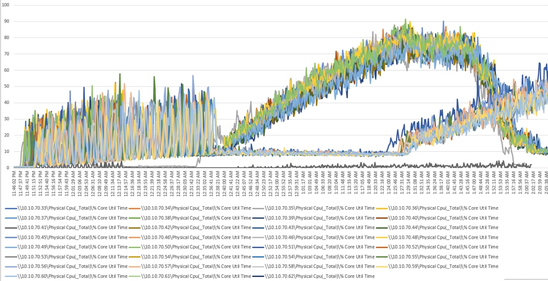
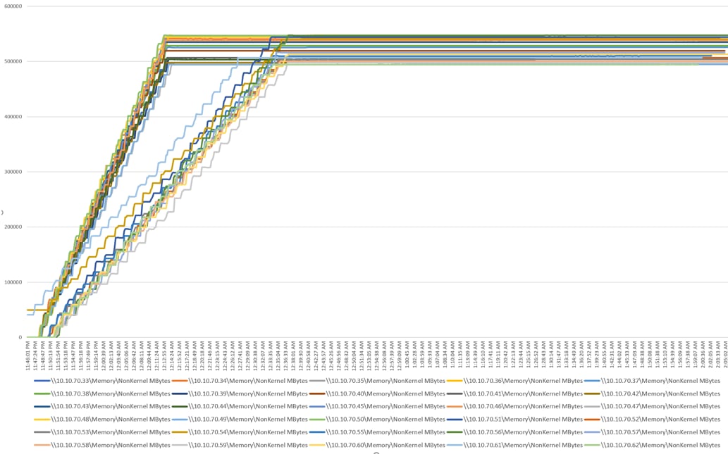
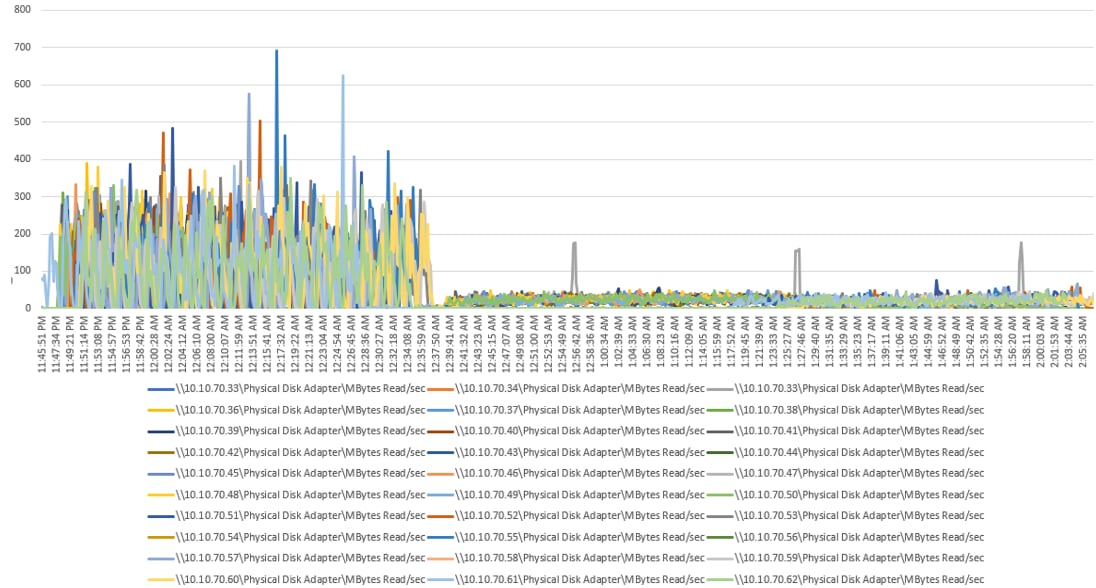
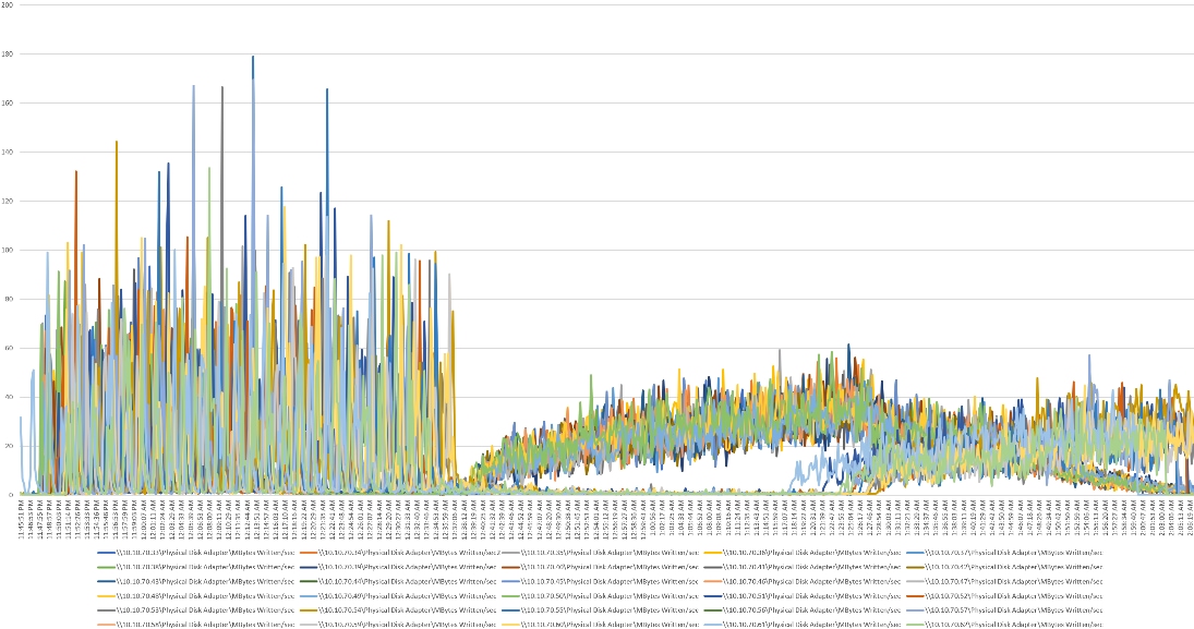
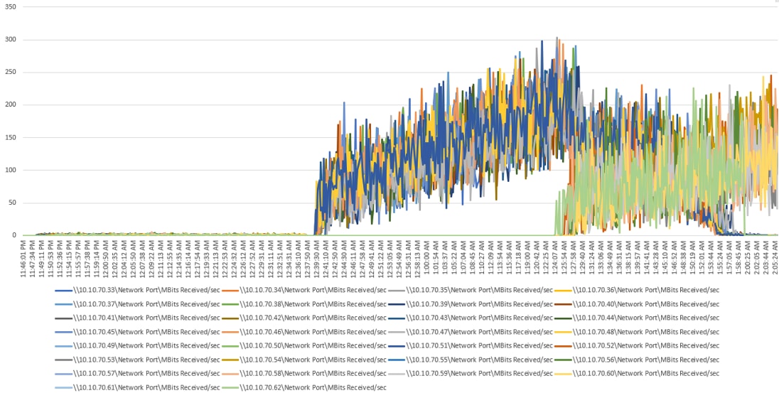
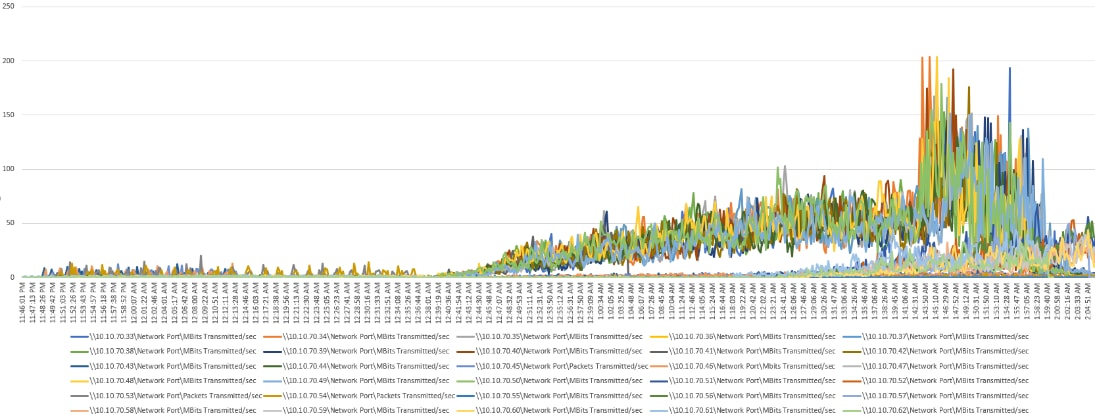
VDI Non-Persistent Performance Monitor Data: 5500 Users Scale Testing
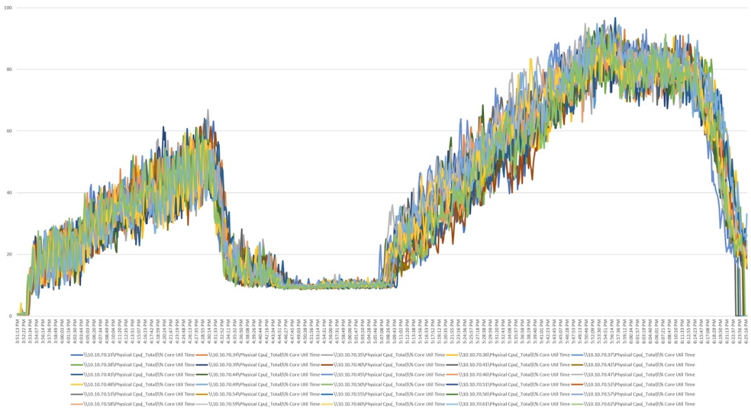
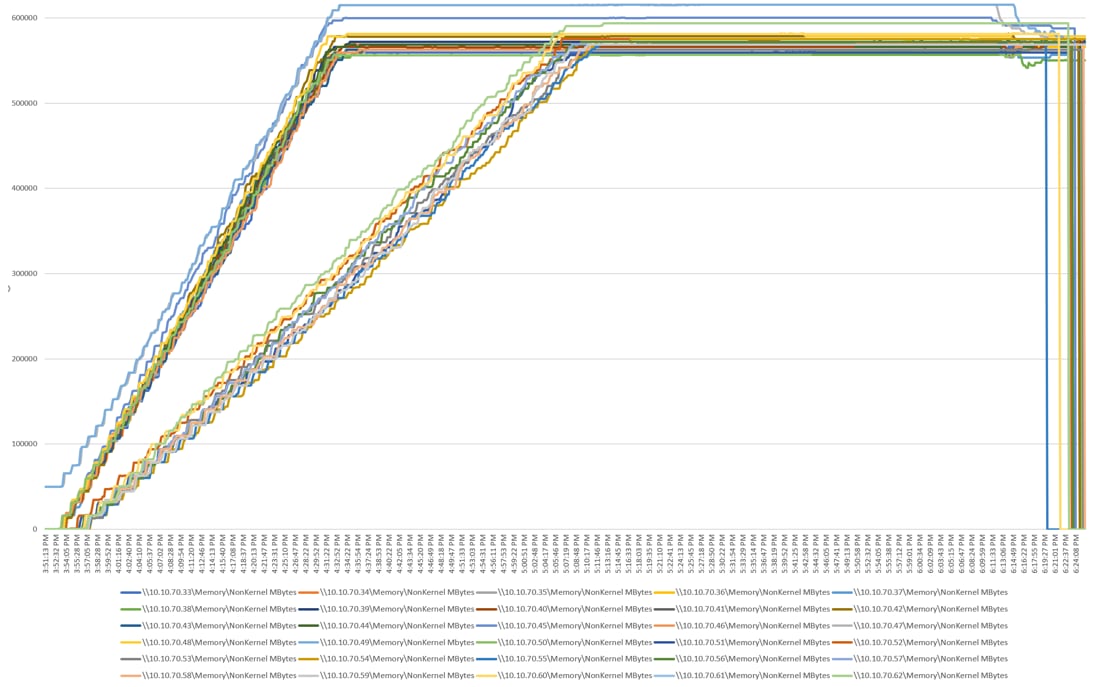
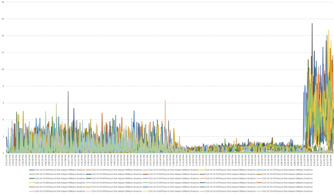
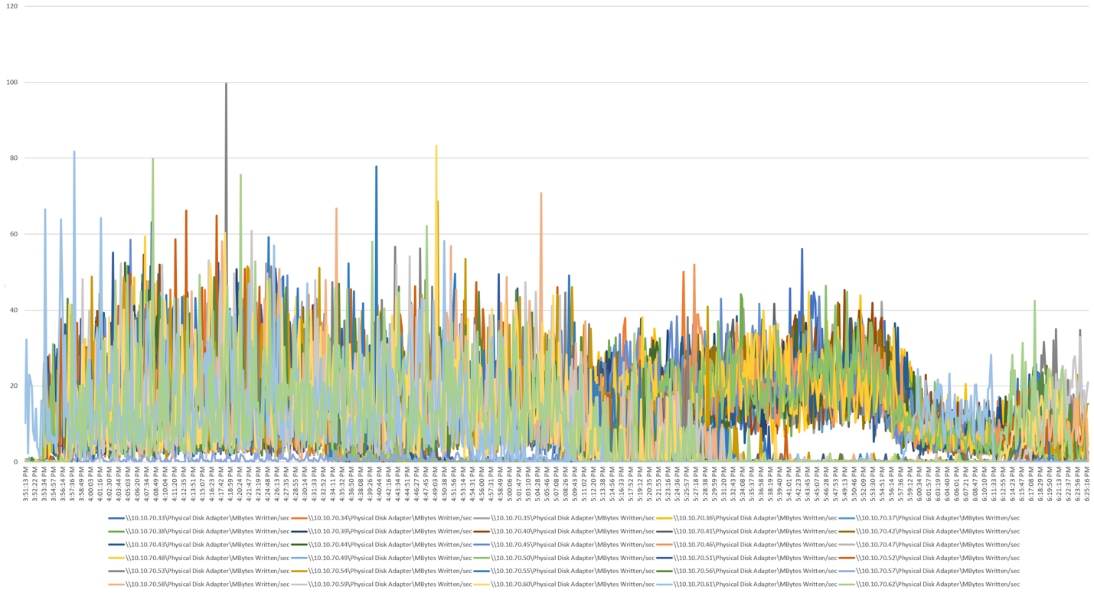
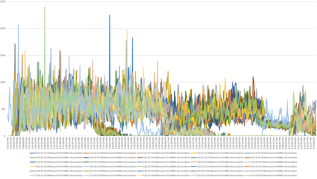
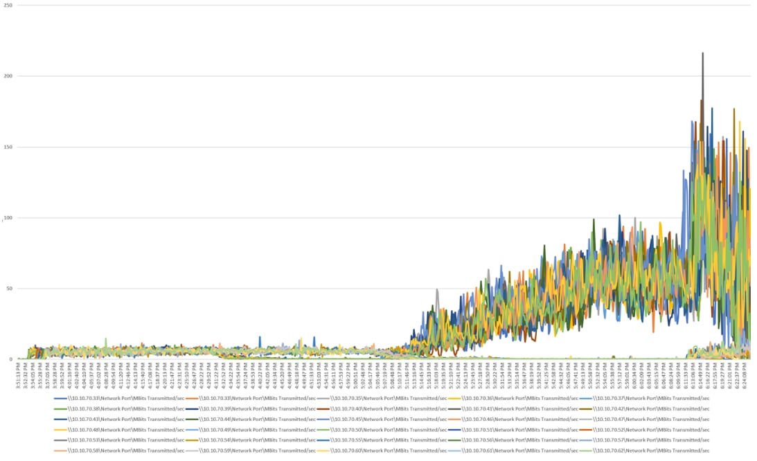
HSD Performance Monitor Data: 6500 Users Scale Testing