Cisco Data Intelligence Platform on Cisco UCS M6 with Cloudera Data Platform Private Cloud
Available Languages
Bias-Free Language
The documentation set for this product strives to use bias-free language. For the purposes of this documentation set, bias-free is defined as language that does not imply discrimination based on age, disability, gender, racial identity, ethnic identity, sexual orientation, socioeconomic status, and intersectionality. Exceptions may be present in the documentation due to language that is hardcoded in the user interfaces of the product software, language used based on RFP documentation, or language that is used by a referenced third-party product. Learn more about how Cisco is using Inclusive Language.
- US/Canada 800-553-2447
- Worldwide Support Phone Numbers
- All Tools
 Feedback
 Feedback
In partnership with:

About the Cisco Validated Design Program
The Cisco Validated Design (CVD) program consists of systems and solutions designed, tested, and documented to facilitate faster, more reliable, and more predictable customer deployments. For more information, go to: http://www.cisco.com/go/designzone.
Today, leading enterprises utilizes artificial intelligence/machine learning (AI/ML) to discover insights hidden in massive amounts of data through data processing and data engineering. As enterprises are adopting to newer AI/ML enabled use cases to support problem solving and progress toward business intelligence goal through revolution of increased computing power, vast amount of data storage and better algorithms are not enough to drive AI/ML enabled business challenges. Adoption, development and scale a cohesive data strategy focused data management platform providing centralized data access to existing and emerging workloads.
Data scientists are utilizing data sets on a magnitude and scale never seen before, implementing use cases such as transforming supply chain models, responding to increased levels of fraud, predicting customer churn, and developing new product lines. To be successful, data scientists need the tools and underlying processing power to train, evaluate, iterate, and retrain their models to obtain highly accurate results. The sheer size of the data to be processed and analyzed has a direct impact on the cost and speed at which companies can train and operate their AI/ML models with dynamic scalability. Data set size can also heavily influence where to deploy infrastructure—whether in a public, private, or hybrid cloud.
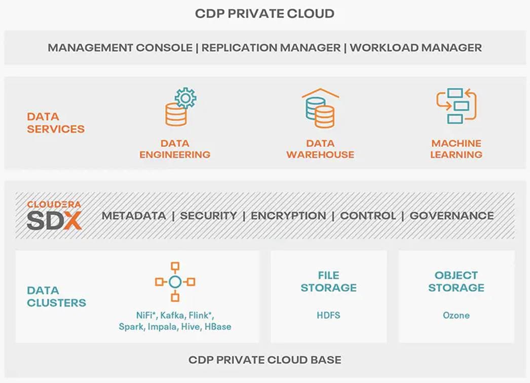
Cloudera Private Cloud enables unified data fabric with broad set of tools and management capability for data analytics and AI/ML use cases along with secure user access and data governance through:
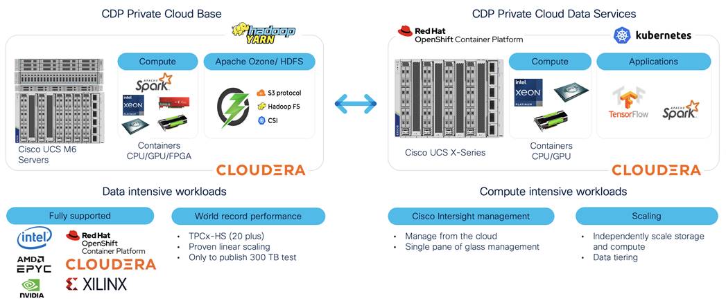
● Cloudera Data Platform Private Cloud Base (CDP PvC Base) - provides storage and supports the traditional data lake environments. It also introduced Apache Ozone, the next generation of filesystem for data lake
● Cloudera Data Platform Private Cloud Data Services (CDP PvC DS) - provides personas (such as data analyst, data scientist, data engineer) driven data services from private and hybrid data lakes.
Cisco Data Intelligence Platform (CDIP) is thoughtfully designed private cloud for data lake. It supports data intensive workloads with Cloudera Data Platform Private Cloud Base and compute rich (AI/ML) and compute intensive workloads with Cloudera Data Platform Private Cloud Data Services. CDIP further provides storage consolidation with Apache Ozone on Cisco UCS infrastructure enables an object store implementation to support several new use cases and higher scale, which is fully managed by Cisco Intersight. Cisco Intersight simplifies management and moves management of computing resources from network to the cloud.
This CVD implements CDIP with cloud advantage in mind for private and hybrid cloud. It is based on Cisco UCS M6 family of servers which support 3rd Gen Intel Xeon Scalable family processors with PCIe Gen 4 capabilities. These servers include the following.
● The Cisco UCS C240 M6 Server for Storage (Apache Ozone and HDFS) - Extends the capabilities of the Cisco UCS rack server portfolio supporting more than 43 percent more cores per socket and 33 percent more memory when compared with the previous generation.
● The Cisco UCS® X-Series with Cisco Intersight - A modular system managed from the cloud. It is
designed to meet the needs of modern applications and improve operational efficiency, agility, and scale through an adaptable, future-ready, and modular design.
Furthermore, with Cisco Intersight you get all the benefits of SaaS delivery and full life cycle management of network and compute. This empowers you to analyze, update, fix, and automate your environment in ways that were not possible before.
This CVD explains the implementation of Cloudera Data Platform Private Cloud Base (CDP PvC) 7.1.7 with CDP Private Cloud Data Services 1.4 running on Red Hat OpenShift Container Platform 4.8.
CDIP with Cloudera Data Platform enables customers to independently scale storage and computing resources as needed while offering an exabyte scale with low total cost of ownership (TCO). It offers future-proof architecture with the latest technologies provided by Cloudera.
This chapter contains the following:
● Audience
Both Big Data and machine learning technology have progressed at a point where they are being implemented in production systems running 24x7. There exists a need for a proven, dependable, and high-performance platform for ingestion, processing, storage, and analysis of the data, as well as the seamless dissemination of the outputs, results, and insights of the analysis.
This solution implements Cloudera Data Platform Private Cloud Base (CDP PvC Base) and Cloudera Data Platform Private Cloud Data Services (CDP PvC DS) on Cisco Data Intelligence Platform (CDIP) architecture, a world-class platform specifically designed for demanding workloads that is both easy to scale and easy to manage, even as the requirements grow to thousands of servers and petabytes of storage.
Today, many companies recognize the immense potential of big data and machine learning technologies. It is also evident that everyday enormous amount of data is being ingested in on-premises or cloud enabled data lakes with very high velocity. It is quite apparent that IT leaders are challenged in finding ways, how to maximize the ROI of their data, extract valuable insights, and make informed business decisions to gain competitive edge. Furthermore, Apps have transformed into whole new thinking of IT. Apps are becoming the “business” from just supporting the business functions. As a result, modernizing apps, adopting cloud-native architectures, creating micro-services, and utilizing advanced analytics using AI/ML frameworks are becoming de-facto standards for digital transformation. Amid those challenges, siloed monolithic apps and data are further slowing down the pace of innovation and limiting their transformation journey towards modern digitization.
Corporations are leveraging new capabilities, building out departments and increasing hiring. However, these efforts have a new set of challenges:
● Making the data available to the diverse set of engineers (Data engineers, analysts, data scientists) who need it
● Enabling access to high-performance computing resources, GPUs, that also scale with the data growth
● Allowing people to work with the data using the environments in which they are familiar
● Publishing their results so the organization can make use of it
● Enabling the automated production of those results
● Managing the data for compliance and governance
● Scaling the system as the data grows
● Managing and administering the system in an efficient, cost-effective way
This solution is based on the Cisco Data Intelligence Platform that includes computing, storage, connectivity, capabilities built on Cisco Unified Computing System (Cisco UCS) infrastructure, using Cisco UCS C-Series and S-Series Rack Servers and unified management with Cisco Intersight to help companies manage the entire infrastructure from a single pane of glass along with Cloudera Data Platform to provide the software for fast ingest of data and managing and processing exabyte scale data being collected. This architecture is specifically designed for performance and linear scalability for big data and machine learning workload.
The intended audience for this document includes, but is not limited to, sales engineers, field consultants, professional services, IT managers, IT engineers, partners, and customers who are interested in learning about and deploying the Cloudera Data Platform Private Cloud (CDP PvC) on the Cisco Data Intelligence Platform on Cisco UCS M6 Rack-Mount servers and Cisco UCS X-Series for digital transformation through cloud-native modern data analytics and AI/ML.
This document describes the architecture, installation, configuration, and validated use cases for the Cisco Data Intelligence Platform using Cloudera Data Platform Private Cloud Base and Cloudera Data Platform Private Cloud Data Services on Cisco UCS M6 Rack-Mount servers and Cisco UCS® X-Series. A reference architecture is provided to configure the Cloudera Data Platform on Cisco UCS X210c Compute Nodes and X440p PCIe node with NVIDIA A100 GPU.
This solution extends the portfolio of Cisco Data Intelligence Platform (CDIP) architecture with Cloudera Data Platform Private Cloud Data Services (CDP PvC DS), a state-of-the-art platform, providing a data cloud for demanding workloads that is easy to deploy, scale and manage which is built on top of Red Hat OpenShift Container Platform (RHOCP). Furthermore, as the enterprise’s requirements and needs changes overtime, the platform can grow to thousands of servers, at exabytes of storage and tens of thousands of cores to process this data.
The following will be implemented in this validated design:
● Cisco Intersight to configure and manage Cisco Infrastructure
● Data lake provided by Cloudera Data Platform Private Cloud Base on Cisco UCS servers
● Compute Farm running
◦ Red Hat OpenShift Container Platform (RHOCP) or deploy an Embedded Container Service (ECS) to provide the Kubernetes and container platform for the private cloud
◦ Cloudera Data Platform Private Cloud Data Services as the application providing data processing, auto scaling and self-service onboarding of the user
In this release, you will be primarily exploring Cloudera Machine Learning as the persona to cater to data scientists. This release of Cloudera Private Cloud Data Services also includes Cloudera Data Warehouse and is not the subject of this document.
This chapter contains the following:
● Cisco Data Intelligence Platform
This CVD details the process of installing CDP Private Cloud including the installation of Red Hat OpenShift Container Platform 4.8, the prerequisites for CDP Private Cloud Data Services and the configuration details of the cluster.
Cisco Data Intelligence Platform
Cisco Data Intelligence Platform (CDIP) is a cloud-scale architecture, primarily for a private cloud data lake which brings together big data, AI/compute farm, and storage tiers to work together as a single entity while also being able to scale independently to address the IT issues in the modern data center. This architecture provides the following:
● Extremely fast data ingest, and data engineering done at the data lake.
● AI compute farm allowing for easy to manage different types of personas to work on AI/ML frameworks while achieving auto-scalability for different compute types (GPU, CPU, FPGA) to work on this data for further analytics.
Note: Cloudera Private Cloud Data Services 1.4 supports GPU only for Cloudera Machine Learning (CML). Cloudera Data Engineering (CDE) will support GPU in future release.
● A storage tier, allowing to gradually retire data which has been worked on to a storage dense system with a lower $/TB providing a better TCO. Next-generation Apache Ozone filesystem for storage in a data lake.
● Seamlessly scale the architecture to thousands of nodes with a single pane of glass management using Cisco Intersight and Cisco Application Centric Infrastructure (ACI).
Cisco Data Intelligence Platform caters to the evolving architecture bringing together a fully scalable infrastructure with centralized management and fully supported software stack (in partnership with industry leaders in the space) to each of these three independently scalable components of the architecture including data lake, AI/ML and Object stores.
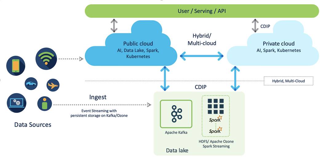
CDIP offers private cloud which enables it to become a hybrid cloud for the data lakes and apps which provides unified user experiences with common identity, single API framework that stretches from private cloud to public cloud, auto-scales when app demand grows. Further, implement tighter control over sensitive data with data governance and compliance, and integrate common data serving layer for data analytics, business intelligence, AI inferencing, and so on.

CDIP with CDP private cloud is built to meet the needs of enterprises for their hybrid cloud with unmatched choices such as any data, any analytics, and engineering anywhere. This solution includes:
● Flexibility to run workload anywhere for quick and easy insights
● Security that is consistent across all clouds provided by Cloudera’s SDX. Write centrally controlled compliance and governance policies once and apply everywhere, enabling safe, secure, and compliant end-user access to data and analytics
● Performance and scale to optimize TCO across your choices. It brings unparalleled scale and performance to your mission-critical applications while securing future readiness for evolving data models
● Single pane of glass visibility for your infrastructure and workloads. Register multi-cloud, including public and private in a single management console and launch virtual analytic workspaces or virtual warehouses within each environment as needed
● Secure data and workload migration to protect your enterprise data and deliver it where is needed. Securely manage data and meta-data migration across all environments
● Unified and multi-function Analytics for cloud-native workloads whether real-time or batch. Integrates data management and analytics experiences across the entire data lifecycle for data anywhere.
● Hybrid and multi-cloud data warehouse service for all modern, self-service, and advanced analytics use cases, at scale.
● Track and Audit everything across entire ecosystem of CDIP deployments
CDIP with CDP Private Cloud Hybrid Uses Cases
With the increasing hybrid cloud adoption due to increasing data volume and variety, CDIP addresses use cases that caters to the needs of today’s demand of hybrid data platforms, such as the following:
● Hybrid Workload – Offload workload on-premises to cloud or vice-versa as per the requirements or auto-scale during peak hours due to real-time urgency or seasonality Cloudera Replication Manager and Cloudera Workload Manager
● Hybrid Pipelines – Implement and optimize data pipelines for easier management. Automate and orchestrate your data pipelines as per demand or where it is needed the most. Implement secure data exchange between choice of your cloud and on-premises data hub at scale
● Hybrid Data Integration – Integrate data sources among clouds. Simplify application development or ML model training that needs on-premises data sources or cloud-native data stores
● Hybrid DevOps – Accelerate development with dev sandboxes in the cloud, however, production runs on-premises
● Hybrid Data Applications – Build applications that runs anywhere for cost, performance, and data residency
Cisco Data Intelligence Platform with Cloudera Data Platform
Cisco developed numerous industry leading Cisco Validated Designs (reference architectures) in the area of Big Data, compute farm with Kubernetes (CVD with RedHat OpenShift Container Platform) and Object store.
A CDIP architecture as a private cloud can be fully enabled by the Cloudera Data Platform with the following components:
● Data lake enabled through CDP PvC Base
● Private Cloud with compute on Kubernetes can be enabled through CDP Private Cloud Data Services
● Exabyte storage enabled through Apache Ozone
This architecture can start from a single rack (Figure 4) and scale to thousands of nodes with a single pane of glass management with Cisco Application Centric Infrastructure (ACI) (Figure 5).
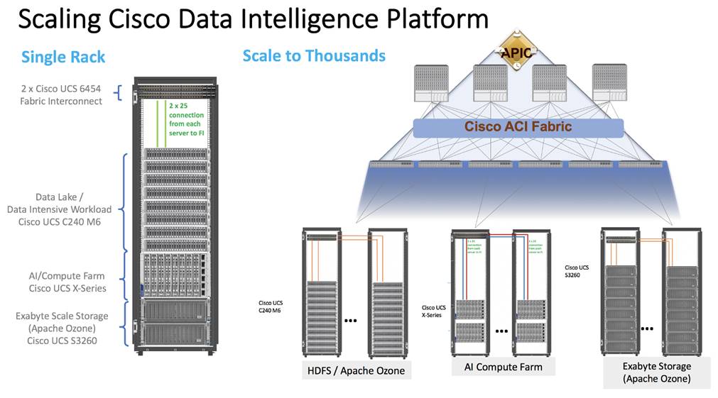
Cisco Data Intelligence Platform reference architectures are carefully designed, optimized, and tested with the leading big data and analytics software distributions to achieve a balance of performance and capacity to address specific application requirements. You can deploy these configurations as is or use them as templates for building custom configurations. You can scale your solution as your workloads demand, including expansion to thousands of servers using Cisco Nexus 9000 Series Switches. The configurations vary in disk capacity, bandwidth, price, and performance characteristics.
Data Lake (CDP PvC Base) Reference Architecture
Table 1 lists the CDIP with CDP PvC data lake and dense storage with Apache Ozone reference architecture.
Table 1. Cisco Data Intelligence Platform with CDP Private Cloud Base (Apache Ozone) Configuration on Cisco UCS M6
|
|
High Performance |
Performance |
Capacity |
| Server |
16 x Cisco UCS C240 M6SN Rack Servers with small-form-factor (SFF) drives |
16 x Cisco UCS C240 M6 Rack Servers with small-form-factor (SFF) drives |
16 x Cisco UCS C240 M6 Rack Servers with large-form-factor (LFF) drives |
| CPU |
2 x 3rd Gen Intel® Xeon® Scalable Processors 6338 processors (2 x 32 cores, at 2.0 GHz) |
2 x 3rd Gen Intel® Xeon® Scalable Processors 6338 processors (2 x 32 cores, at 2.0 GHz) |
2 x 3rd Gen Intel® Xeon® Scalable Processors 6338 processors (2 x 32 cores, at 2.0 GHz) |
| Memory |
16 x 32 GB RDIMM DRx4 3200 MHz (512 GB) |
16 x 32 GB RDIMM DRx4 3200 MHz (512 GB) |
16 x 32 GB RDIMM DRx4 3200 MHz (512 GB) |
| Boot |
M.2 with 2 x 960-GB SSDs |
M.2 with 2 x 960-GB SSDs |
M.2 with 2 x 960-GB SSDs |
| Storage |
24 x 6.4TB 2.5in U2 NVMe and 2 x 3.2TB NVMe |
24 x 2.4TB 12G SAS 10K RPM SFF HDD (4K) (or 24 x 7.6TB Enterprise Value 12G SATA SSDs) and 2 x 3.2TB NVMe |
16 x 16TB 12G SAS 7.2K RPM LFF HDD(4K) and 2 x 3.2TB NVMe |
| Virtual Interface Card (VIC) |
Cisco UCS VIC 1467 (4 x 10/25G) Cisco UCS VIC 1477 (2 x 40/100G) Cisco UCS VIC 15428 (4 x 10/25/50G) |
Cisco UCS VIC 1467 (4 x 10/25G) Cisco UCS VIC 1477 (2 x 40/100G) Cisco UCS VIC 15428 (4 x 10/25/50G) |
Cisco UCS VIC 1467 (4 x 10/25G) Cisco UCS VIC 1477 (2 x 40/100G) Cisco UCS VIC 15428 (4 x 10/25/50G) |
| Storage Controller |
NA |
Cisco 12-Gbps SAS modular RAID controller with 4-GB flash-based write cache (FBWC) or Cisco 12-Gbps modular SAS host bus adapter (HBA) |
Cisco 12-Gbps SAS modular RAID controller with 4-GB FBWC or Cisco 12-Gbps modular SAS host bus adapter (HBA) |
| Network Connectivity |
Cisco UCS 6400 or 6500 Fabric Interconnect |
Cisco UCS 6400 or 6500 Fabric Interconnect |
Cisco UCS 6400 or 6500 Fabric Interconnect |
| GPU (optional) |
NVIDIA GPU A100 |
NVIDIA GPU A100 |
NVIDIA GPU A100 |
Note: Reference architecture highlighted here is the sizing guide for Apache Ozone based deployment. When sizing data lake for HDFS, Cloudera doesn’t support exceeding 100TB per data node and drives larger than 8TB. For more information, visit HDFS and Ozone section in CDP PvC Base hardware requirement: https://docs.cloudera.com/cdp-private-cloud-base/7.1.7/installation/topics/cdpdc-runtime.html
Compute Farm (CDP PvC DS) Reference Architecture
Table 2 lists the CDIP with CDP PvC DS configuration for master and worker nodes with RHOCP reference architecture.
Table 2. Cisco Data Intelligence Platform with CDP Private Cloud Data Services Configuration
|
|
High Core Option |
| Servers |
Cisco UCS X-Series 9508 chassis with X210C Blades (Up to 8 Per chassis) |
| CPU |
2 x 3rd Gen Intel® Xeon® Scalable Processors 6338 processors (2 x 32 cores, at 2.0 GHz) |
| Memory |
16 x 64GB RDIMM DRx4 3200 MHz (1TB) |
| Boot |
M.2 with 2 x 960GB SSD |
| Storage |
4 x 3.2TB 2.5in U2 NVMe* (Red Hat OpenShift Container Storage (RHOCS)/Portworx [2 drives], Local storage [2 drives]) |
| VIC |
Cisco UCS VIC 14425 4x25G mLOM or Cisco UCS VIC 15231 2x100/200G mLOM |
| Storage controller |
Cisco UCS X210c Compute Node compute pass through controller |
| Network connectivity |
Cisco UCS 6400 or 6500 Fabric Interconnect |
| GPU (optional) |
Cisco UCS X440p with NVIDIA A100 GPU |
Note: NVMe storage capacity and quantity needs to be updated based on the dataset requirement. For more information, visit CDP PvC DS with RHOCP hardware requirements: https://docs.cloudera.com/cdp-private-cloud-data-services/1.4.0/installation/topics/cdppvc-installation-openshift-requirements.html
Note: This deployment guide was tested with Cisco UCS Fabric Interconnect 6454 connected to Cisco UCS X9508 chassis via UCS 9108-25G IFM. Cisco UCS X9416 X-Fabric Module for 9508 chassis provides native PCIe Gen4 x16 connectivity to the X210c compute and Cisco UCS X440p PCIe node. For more details: https://www.cisco.com/c/dam/en/us/products/collateral/servers-unified-computing/ucs-x-series-modular-system/x9508-specsheet.pdf
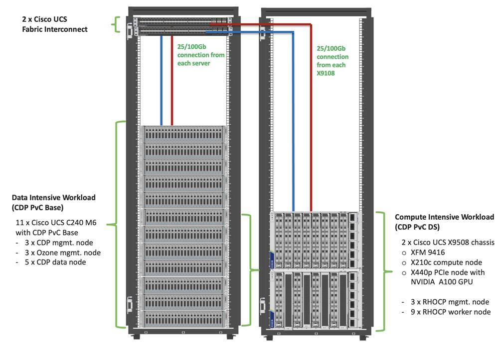
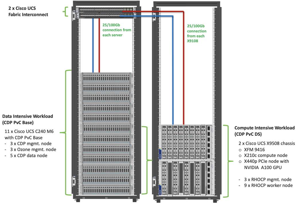
As illustrated in Figure 4, this CVD was designed with the following:
● 3 x Cisco UCS X210C compute node with RedHat OpenShift Container Platform master node
● 5 x Cisco UCS X210C compute node with RedHat OpenShift Container Platform worker nodes
● 4 x Cisco UCS X210c compute node and 4 x Cisco UCS X440p PCIe node hosting 2 x NVIDIA A100 GPU per node with RedHat OpenShift Container Platform worker nodes
● Cloudera Data Platform Private Cloud Data Services running on RedHat OpenShift Container Platform
● 1 x Cisco UCS C240 M6 bootstrap node for RedHat OpenShift Container Platform
● 1 x Cisco UCS C240 M6 running HA Proxy
● Cloudera Data Platform Private Cloud Base running the Cloudera manager.
Refer to http://www.cisco.com/go/bigdata_design to build a fully supported CDP Private Cloud Base on CDIP reference architecture. This CVD does not provide the details to build a CDP Private Cloud Base. For detailed instruction, click the following links:
Cisco Data Intelligence Platform on Cisco UCS M6 with Cloudera Data Platform Ozone Design Guide
Cisco Data Intelligence Platform with All NVMe Storage, Cisco Intersight, and Cloudera Data Platform
Cisco Data Intelligence Platform on Cisco UCS S3260 with Cloudera Data Platform
Note: The bootstrap controller node is not shown in the reference architecture (Figure 4). The bootstrap node is temporary and is used to deploy OpenShift control plane, once OpenShift masters are up, it can be removed.
Note: HAproxy server is used for load balancing OpenShift control and application traffic. It is recommended to use external load balancer in production environment or implement HA for HAproxy load balancers with keepalived VIP.
This chapter contains the following:
● Cisco Data Intelligence Platform
● Cisco Unified Computing System
● Cisco UCS Fabric Interconnect
● Cloudera Data Platform (CDP)
● Cloudera Machine Learning (CML)
● Cloudera Data Warehouse (CDW)
● Cloudera Data Engineering (CDE)
Cisco Data Intelligence Platform
This section describes the components used to build Cisco Data Intelligence Platform, a highly scalable architecture designed to meet a variety of scale-out application demands with seamless data integration and management integration capabilities.
Cisco Data Intelligence Platform powered by Cloudera Data Platform delivers:
● Latest generation of CPUs from Intel (3rd generation Intel Scalable family, with Ice Lake CPUs).
● Cloud scale and fully modular architecture where big data, AI/compute farm, and massive storage tiers work together as a single entity and each CDIP component can also scale independently to address the IT issues in the modern data center.
● World record Hadoop performance both for MapReduce and Spark frameworks published at TPCx-HS benchmark.
● AI compute farm offers different types of AI frameworks and compute types (GPU, CPU, FPGA) to work data for analytics.
● A massive storage tier enables to gradually retire data and quick retrieval when needed on a storage dense sub-system with a lower $/TB providing a better TCO.
● Data compression with FPGA, offload compute-heavy compression tasks to FPGA, relieve CPU to perform other tasks, and gain significant performance.
● Seamlessly scale the architecture to thousands of nodes.
● Single pane of glass management with Cisco Intersight.
● ISV Partner ecosystem – Top notch ISV partner ecosystem, offering best of the breed end-to-end validated architectures.
● Pre-validated and fully supported platform.
● Disaggregate Architecture supports separation of storage and compute for a data lake.
● Container Cloud, Kubernetes, compute farm backed by the industry leading container orchestration engine and offers the very first container cloud plugged with data lake and object store.
Cloudera Data Platform Private Cloud Base (CDP PvC Base)
With the merger of Cloudera and Hortonworks, a new “Cloudera” software named Cloudera Data Platform (CDP) combined the best of Hortonwork’s and Cloudera’s technologies to deliver the industry leading first enterprise data cloud. CDP Private Cloud Base is the on-prem version of CDP and CDP Private Cloud Data Services is the on-prem version of Private Cloud to enable compute on Kubernetes with Red Hat OpenShift Container Platform. This unified distribution is a scalable and customizable platform where workloads can be securely provisioned. CDP gives a clear path for extending or refreshing your existing HDP and CDH deployments and set the stage for cloud-native architecture.
Apache Ozone Object Store
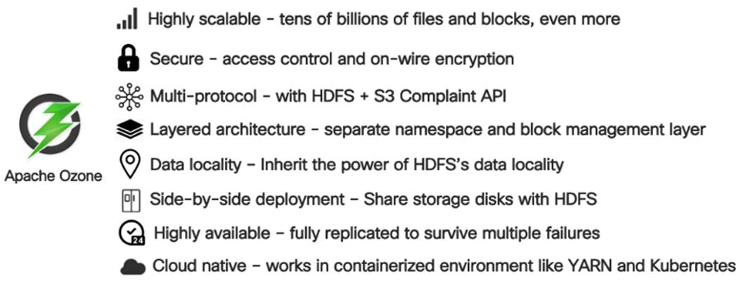
Apache Ozone is a scalable, redundant, and distributed object store for Hadoop. Apart from scaling to billions of objects of varying sizes, Ozone can function effectively in containerized environments such as Kubernetes and YARN. Applications using frameworks like Apache Spark, YARN, and Hive work natively without any modifications. Ozone is built on a highly available, replicated block storage layer called Hadoop Distributed Data Store (HDDS).
Ozone is a scale-out architecture with minimal operational overheads and long-term maintenance efforts. Ozone can be co-located with HDFS with single security and governance policies for easy data exchange or migration and offers seamless application portability. Ozone enables separation of compute and storage via the S3 API as well as like HDFS, it also supports data locality for applications that choose to use it.
The design of Ozone was guided by the following key principles:
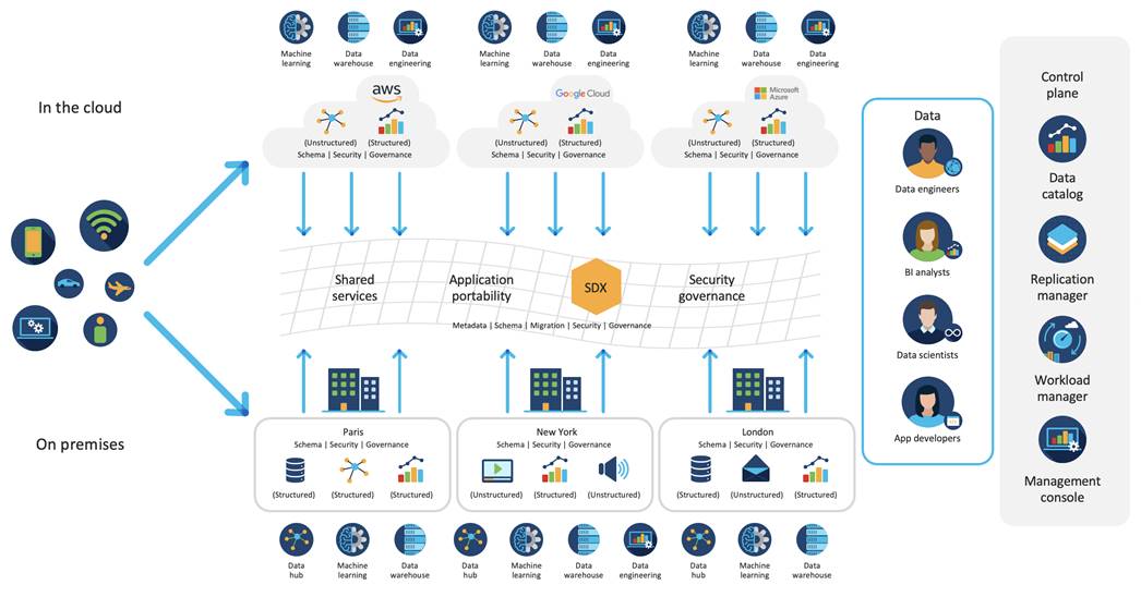
CDIP with CDP Hybrid Cloud Architecture
Cisco Data Intelligent Platform (CDIP) with Cloudera Data Platform (CDP) integrates different domains, such as specific layers of compute infrastructure between on-premises environments and public clouds. Integrations can include moving a Kubernetes-based application to establish secure connectivity, user access, or policies per workloads between environments. These hybrid cloud architecture frameworks and operating models are better defined with the more encompassing term hybrid IT, which also includes multi-cloud scenarios enabling distributed nature of the infrastructure that can assure elasticity, scalability, performance, and efficiency as well as bring apps closer to their intended users with ability to cloud burst.
Red Hat OpenShift or Embedded Container Service (ECS) being the preferred container cloud platform for CDP private cloud and so is for CDIP, is the market leading Kubernetes powered container platform. This combination is the first enterprise data cloud with a powerful hybrid architecture that decouples compute and storage for greater agility, ease-of-use, and more efficient use of private and multi-cloud infrastructure resources. With Cloudera’s Shared Data Experience (SDX), security and governance policies can be easily and consistently enforced across data and analytics in private as well as multi-cloud deployments. This hybridity will open myriad opportunities for seamless portability of workloads and applications for multi-function integration with other frameworks such as streaming data, batch workloads, analytics, data pipelining/engineering, and machine learning.
Cloud Native Architecture for Data Lake and AI
Cisco Data Intelligence Platform with CDP private cloud accelerates the process of becoming cloud-native for your data lake and AI/ML workloads. By leveraging Kubernetes powered container cloud, enterprises can now quickly break the silos in monolithic application frameworks and embrace a continuous innovation of micro-services architecture with CI/CD approach. With cloud-native ecosystem, enterprises can build scalable and elastic modern applications that extends the boundaries from private cloud to hybrid.
Containerization
Hadoop 3.0 introduced production-ready Docker container support on YARN with GPU isolation and scheduling. This created plethora of opportunities for modern applications, such as micro-services and distributed applications frameworks comprised of 1000s of containers to execute AI/ML algorithms on Peta bytes of data with ease and in a speedy fashion.
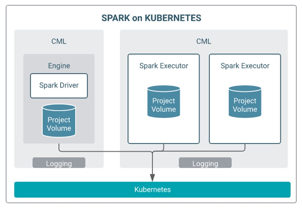
Apache Spark 3.0
Apache Spark 3.0 is a highly anticipated release. To meet this expectation, Spark is no longer limited just to CPU for its workload, it now offers GPU isolation and pooling GPUs from different servers to accelerated compute. To easily manage the deep learning environment, YARN launches the Spark 3.0 applications with GPU. This prepares the other workloads, such as Machine Learning and ETL, to be accelerated by GPU for Spark Workloads. Cisco Blog on Apache Spark 3.0
Cisco Unified Computing System
Cisco Unified Computing System (Cisco UCS) is a next-generation data center platform that integrates computing, networking, storage access, and virtualization resources into a cohesive system designed to reduce total cost of ownership and increase business agility. The system integrates a low-latency, lossless 10-100 Gigabit Ethernet unified network fabric with enterprise-class, x86-architecture servers. The system is an integrated, scalable, multi-chassis platform with a unified management domain for managing all resources.
Cisco Unified Computing System is revolutionizing the way servers are managed in the datacenter. The following are the unique differentiators of Cisco Unified Computing System and Cisco UCS Manager:
● Embedded Management—In Cisco UCS, the servers are managed by the embedded firmware in the Fabric Inter-connects, eliminating the need for any external physical or virtual devices to manage the servers.
● Unified Fabric—In Cisco UCS, from blade server chassis or rack servers to FI, there is a single Ethernet cable used for LAN, SAN, and management traffic. This converged I/O results in reduced cables, SFPs and adapters – reducing capital and operational expenses of the overall solution.
● Auto Discovery—By simply inserting the blade server in the chassis or connecting the rack server to the fabric interconnect, discovery and inventory of compute resources occurs automatically without any management intervention. The combination of unified fabric and auto-discovery enables the wire-once architecture of Cisco UCS, where compute capability of Cisco UCS can be extended easily while keeping the existing external connectivity to LAN, SAN, and management networks.
Cisco UCS Manager (UCSM) provides unified, integrated management for all software and hardware components in Cisco UCS. Using Cisco Single Connect technology, it manages, controls, and administers multiple chassis for thousands of virtual machines. Administrators use the software to manage the entire Cisco Unified Computing System as a single logical entity through an intuitive graphical user interface (GUI), a command-line interface (CLI), or a through a robust application programming interface (API).
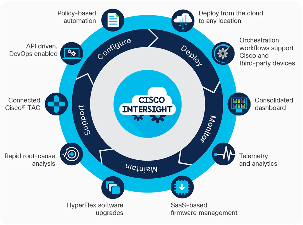
Cisco Intersight is a lifecycle management platform for your infrastructure, regardless of where it resides. In your enterprise data center, at the edge, in remote and branch offices, at retail and industrial sites—all these locations present unique management challenges and have typically required separate tools. Cisco Intersight Software as a Service (SaaS) unifies and simplifies your experience of the Cisco Unified Computing System (Cisco UCS) and Cisco HyperFlex systems. See Figure 11.
The Cisco UCS Fabric Interconnect (FI) is a core part of the Cisco Unified Computing System, providing both network connectivity and management capabilities for the system. Depending on the model chosen, the Cisco UCS Fabric Interconnect offers line-rate, low-latency, lossless 10/25/40/100 Gigabit Ethernet, Fibre Channel over Ethernet (FCoE) and Fibre Channel connectivity. Cisco UCS Fabric Interconnects provide the management and communication backbone for the Cisco UCS C-Series, B-Series and X-Series Blade Servers, and 9508 Series Blade Server Chassis. All servers and chassis, and therefore all blades, attached to the Cisco UCS Fabric Interconnects become part of a single, highly available management domain. In addition, by supporting unified fabrics, the Cisco UCS Fabric Interconnects provide both the LAN and SAN connectivity for all servers within its domain.
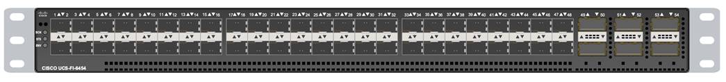
The Cisco UCS 6454 54-Port Fabric Interconnect (Figure 12) is a One-Rack-Unit (1RU) 10/25/40/100 Gigabit Ethernet, FCoE, and Fibre Channel switch offering up to 3.82 Tbps throughput and up to 54 ports. The switch has 28 10/25-Gbps Ethernet ports, 4 1/10/25- Gbps Ethernet ports, 6 40/100-Gbps Ethernet uplink ports, and 16 unified ports that can support 10/25-Gbps Ethernet ports or 8/16/32-Gbps Fibre Channel ports. All Ethernet ports are capable of supporting FCoE.
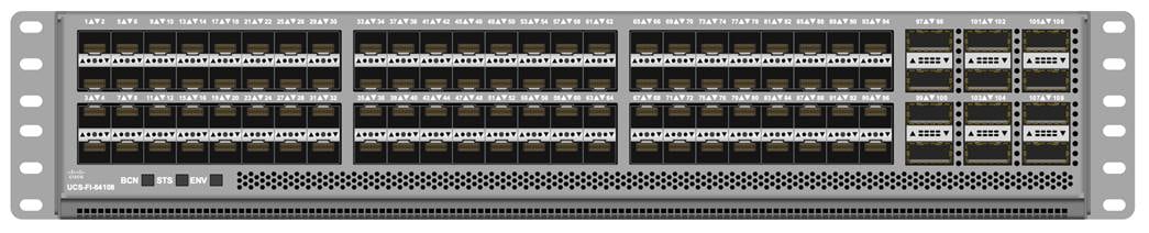
The Cisco UCS 64108 Fabric Interconnect (Figure 13) is a 2-RU top-of-rack switch that mounts in a standard 19-inch rack such as the Cisco R Series rack. The 64108 is a 10/25/40/100 Gigabit Ethernet, FCoE and Fiber Channel switch offering up to 7.42 Tbps throughput and up to 108 ports. The switch has 16 unified ports (port numbers 1-16) that can support 10/25-Gbps SFP28 Ethernet ports or 8/16/32-Gbps Fibre Channel ports, 72 10/25-Gbps Ethernet SFP28 ports (port numbers 17-88), 8 1/10/25-Gbps Ethernet SFP28 ports (port numbers 89-96), and 12 40/100-Gbps Ethernet QSFP28 uplink ports (port numbers 97-108). All Ethernet ports are capable of supporting FCoE.
Cisco UCS C-Series Rack-Mount Servers
Cisco UCS C-Series Rack-Mount Servers keep pace with Intel Xeon processor innovation by offering the latest processors with increased processor frequency and improved security and availability features. With the increased performance provided by the Intel Xeon Scalable Family Processors, Cisco UCS C-Series servers offer an improved price-to-performance ratio. They also extend Cisco UCS innovations to an industry-standard rack-mount form factor, including a standards-based unified network fabric, Cisco VN-Link virtualization support, and Cisco Extended Memory Technology.
It is designed to operate both in standalone environments and as part of Cisco UCS managed configuration, these servers enable organizations to deploy systems incrementally—using as many or as few servers as needed—on a schedule that best meets the organization’s timing and budget. Cisco UCS C-Series servers offer investment protection through the capability to deploy them either as standalone servers or as part of Cisco UCS. One compelling reason that many organizations prefer rack-mount servers is the wide range of I/O options available in the form of PCIe adapters. Cisco UCS C-Series servers support a broad range of I/O options, including interfaces supported by Cisco and adapters from third parties.
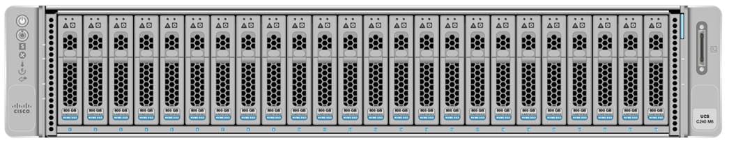
Cisco UCS C240 M6 Rack-Mount Server
The Cisco UCS C240 M6 Rack Server is well-suited for a wide range of storage and I/O-intensive applications such as big data analytics, databases, collaboration, virtualization, consolidation, and high-performance computing in its two-socket, 2RU form factor.
The Cisco UCS C240 M6 Server extends the capabilities of the Cisco UCS rack server portfolio with 3rd Gen Intel Xeon Scalable Processors supporting more than 43 percent more cores per socket and 33 percent more memory when compared with the previous generation.
You can deploy the Cisco UCS C-Series rack servers as standalone servers or as part of the Cisco Unified Computing System managed by Cisco Intersight, or Intersight Managed Mode to take advantage of Cisco® standards-based unified computing innovations that can help reduce your Total Cost of Ownership (TCO) and increase your business agility.
These improvements deliver significant performance and efficiency gains that will improve your application performance. The Cisco UCS C240 M6 Rack Server delivers outstanding levels of expandability and performance.
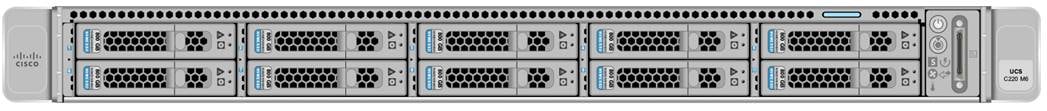
The Cisco UCS C220 M6 Rack Server is the most versatile general-purpose infrastructure and application server in the industry. This high-density, 1RU, 2-socket rack server delivers industry-leading performance and efficiency for a wide range of workloads, including virtualization, collaboration, and bare-metal applications. You can deploy the Cisco UCS C-Series Rack Servers as standalone servers or as part of the Cisco Unified Computing System managed by Cisco Intersight, Cisco UCS Manager, or Intersight Managed Mode to take advantage of Cisco® standards-based unified computing innovations that can help reduce your Total Cost of Ownership (TCO) and increase your business agility.
The Cisco UCS C220 M6 Rack Server extends the capabilities of the Cisco UCS rack server portfolio. The Cisco UCS C220 M6 Rack Server delivers outstanding levels of expandability and performance.
Cisco UCS X-Series Modular System
The Cisco UCS® X-Series with Cisco Intersight is a modular system managed from the cloud. It is designed to meet the needs of modern applications and improve operational efficiency, agility, and scale through an adaptable, future-ready, modular design.
Designed to deploy and automate hybrid cloud environments:
● Simplify with cloud-operated infrastructure
● Simplify with an adaptable system designed for modern applications
● Simplify with a system engineered for the future
For more details, visit https://www.cisco.com/c/dam/en/us/products/collateral/servers-unified-computing/ucs-x-series-modular-system/x9508-specsheet.pdf
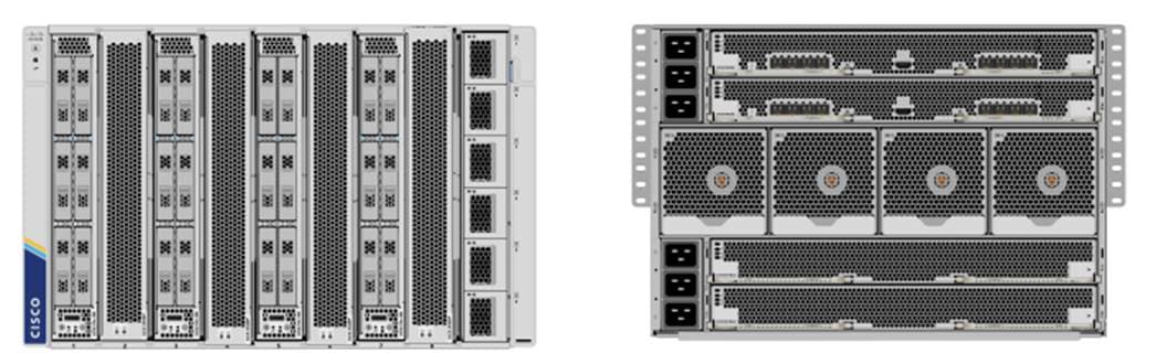
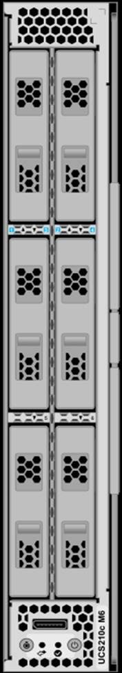
Cisco UCS X210c Compute Node
The Cisco UCS X210c M6 Compute Node is the first computing device to integrate into the Cisco UCS X-Series Modular System. Up to eight compute nodes can reside in the 7-Rack-Unit (7RU) Cisco UCS X9508 Chassis, offering one of the highest densities of compute, IO, and storage per rack unit in the industry.
The Cisco UCS X210c M6 server form factor offers more I/O, more storage, better cooling, and seamless upgrades to connectivity technologies. Its features include the following:
● The 14000 and 15000 Series VICs supply more aggregate bandwidth with up to 200 Gbps per server.
● With six large-capacity drives, the UCS X210c M6 can be used for many workloads that used to require a rack server simply because of the storage requirements.
● Optionally, if you run workloads that require graphical acceleration, you can have two drives and up to two GPUs.
● The X201c node supports Cisco UCS X-Fabric Technology for additional GPUs and future storage and memory options.
● Its vertical orientation and design allow for better airflow, increasing cooling for better reliability.
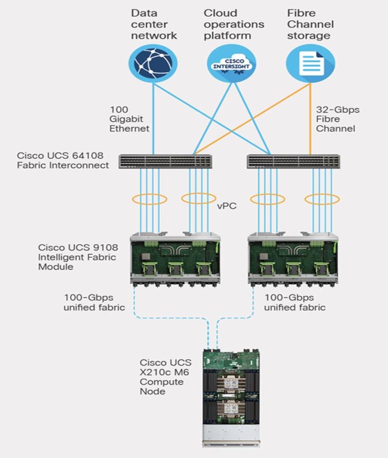
A unified fabric interconnects all devices in the system. It securely carries all traffic to the fabric interconnects where it can be broken out into IP networking, Fibre Channel SAN, and management connectivity.
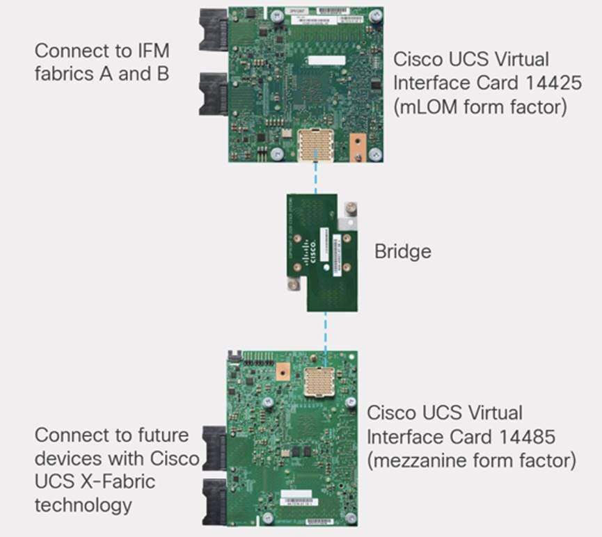
Cisco UCS Virtual Interface Card
Configuring your Cisco UCS X210c M6 Compute Node with both mLOM-and mezzanine-form-factor virtual interface card delivers up to 200 Gbps of network bandwidth to the node and prepares it for future devices with Cisco UCS X-Fabric technology.
The number and types of I/O devices are configured on demand through Intersight management.
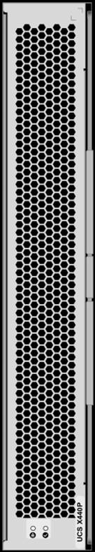
The Cisco UCS X440p PCIe Node is the first PCIe resource node to integrate into the Cisco UCS X-Series Modular System. The Cisco UCS X9508 Chassis has eight node slots, up to four of which can be X440p PCIe nodes when paired with a Cisco UCS X210c M6 Compute Node. The Cisco UCS X440p PCIe Node supports two x16 full-height, full-length dual slot PCIe cards, or four x8 full-height, full-length single slot PCIe cards and requires both Cisco UCS 9416 X-Fabric modules for PCIe connectivity. This provides up to 16 GPUs per chassis to accelerate your applications with the Cisco UCS X440p Nodes. If your application needs even more GPU acceleration, up to two additional GPUs can be added on each Cisco UCS X210c compute node.
Benefits include:
● Accelerate more workloads with up to four GPUs
● Make it easy to add, update, and remove GPUs to Cisco UCS® X210c M6 Compute Nodes
● Get a zero-cable solution for improved reliability and ease of installation
● Have industry standard PCIe Gen 4 connections for compatibility
Ready for a Hybrid Cloud World
The Cisco Intersight cloud operations platform is the force that transforms the Cisco UCS X-Series Modular System from a set of components into a flexible server platform to propel your most important workloads.
The Cisco UCS X-Series with Intersight is built with a common purpose: to make hardware think like software so that you can easily adapt to a rapidly changing world. Through server profiles, Intersight defines the identity, connectivity, and I/O configuration of your servers and automates the entire infrastructure lifecycle. It’s easy to imagine how, as more features are released, the modular system supports a pool of I/O resources: banks of nonvolatile memory, GPU accelerators, specialized ASICs, and massive amounts of NVMe storage. Just as the chassis and Cisco UCS X-Fabric technology are designed to incorporate a constant flow of new capabilities, Cisco Intersight is designed to automatically integrate those technologies into servers along with a constant flow of new, higher-level management capabilities. Software as a service (SaaS) meets modular, infrastructure as code, and the line between hardware and software dissolves.
With Cisco Intersight and the Cisco UCS X-Series you can:
● Define desired system configurations based on policies that use pools of resources provided by the Cisco UCS X-Series. Let Cisco Intersight assemble the components and set up everything from firmware levels to which I/O devices are connected. Infrastructure is code, so your IT organization can use the Intersight GUI, and your DevOps teams can use the Intersight API, the Intersight Service for HashiCorp Terraform, or the many API bindings from languages such as Python and PowerShell.
● Deploy from the cloud to any location. Anywhere the cloud reaches, Intersight can automate your IT processes. We take the guesswork out of implementing new services with a curated set of services we bundle with the Intersight Kubernetes Service, for example.
● Visualize the interdependencies between software components and how they use the infrastructure that supports them with Intersight Workload Optimizer.
● Optimize your workload by analyzing runtime performance and make resource adjustments and workload placements to keep response time within a desired range. If your first attempt at matching resources to workloads doesn’t deliver the results you need, you can reshape the system quickly and easily. Cisco Intersight facilitates deploying workloads into your private cloud and into the public cloud. Now one framework bridges your core, cloud, and edge infrastructure, managing infrastructure and workloads wherever they are deployed.
● Maintain your infrastructure with a consolidated dashboard of infrastructure components regardless of location. Ongoing telemetry and analytics give early detection of possible failures. Reduce risk of configuration drift and inconsistent configurations through automation with global policy enforcement.
● Support your infrastructure with AI-driven root-cause analysis and automated case support for the always-connected Cisco Technical Assistance Center (Cisco TAC). Intersight watches over you when you update your solution stack, helping to prevent incompatible hardware, firmware, operating system, and hypervisor configurations.
Modular Management Architecture
Cisco Intersight is a unified, secure, modular platform that consists of a set of services that bridge applications and infrastructure to meet your specific needs, including:
● Intersight Infrastructure Service
Manage your infrastructure lifecycle, including Cisco data center products, Cisco converged infrastructure solutions, and third-party endpoints
● Intersight Workload Optimizer
Revolutionize how you manage application resources across any environment with real-time, full-stack visibility to help ensure performance and better cost control
● Intersight Kubernetes Service
Simplify Kubernetes with automated lifecycle management across your multi-cloud environment
● Intersight Virtualization Service
Deploy and manage virtual machines on premises or in the cloud
● Intersight Cloud Orchestrator
Standardize application lifecycle management across multiple clouds
Cisco Intersight is Cisco’s systems management platform that delivers intuitive computing through cloud-powered intelligence. This platform offers a more intelligent level of management that enables IT organizations to analyze, simplify, and automate their environments in ways that were not possible with prior generations of tools. This capability empowers organizations to achieve significant savings in Total Cost of Ownership (TCO) and to deliver applications faster, so they can support new business initiatives.
Cisco Intersight is a Software as a Service (SaaS) infrastructure management which provides a single pane of glass management of CDIP infrastructure in the data center. Cisco Intersight scales easily, and frequent updates are implemented without impact to operations. Cisco Intersight Essentials enables customers to centralize configuration management through a unified policy engine, determine compliance with the Cisco UCS Hardware Compatibility List (HCL), and initiate firmware updates. Enhanced capabilities and tight integration with Cisco TAC enables more efficient support. Cisco Intersight automates uploading files to speed troubleshooting. The Intersight recommendation engine provides actionable intelligence for IT operations management. The insights are driven by expert systems and best practices from Cisco.
Cisco Intersight offers flexible deployment either as Software as a Service (SaaS) on Intersight.com or running on your premises with the Cisco Intersight virtual appliance. The virtual appliance provides users with the benefits of Cisco Intersight while allowing more flexibility for those with additional data locality and security requirements.
Cisco Intersight provides the following features for ease of operations and administration for the IT staff:
● Connected TAC
● Security Advisories
● Hardware Compatibility List (HCL)
To learn more about all the features of Cisco Intersight, go to: https://www.cisco.com/c/en/us/products/servers-unified-computing/intersight/index.html
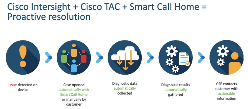
Connected TAC is an automated transmission of technical support files to the Cisco Technical Assistance Center (TAC) for accelerated troubleshooting.
Cisco Intersight enables Cisco TAC to automatically generate and upload Tech Support Diagnostic files when a Service Request is opened. If you have devices that are connected to Intersight but not claimed, Cisco TAC can only check the connection status and will not be permitted to generate Tech Support files. When enabled, this feature works in conjunction with the Smart Call Home service and with an appropriate service contract. Devices that are configured with Smart Call Home and claimed in Intersight can use Smart Call Home to open a Service Request and have Intersight collect Tech Support diagnostic files.
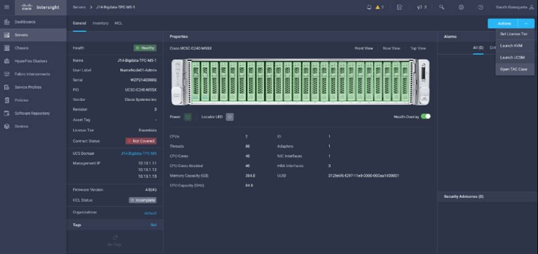
Procedure 1. Enable Connected TAC
Step 1. Log into Intersight.com.
Step 2. Click the Servers tab. Go to Server > Actions tab. From the drop-down list, click Open TAC Case.
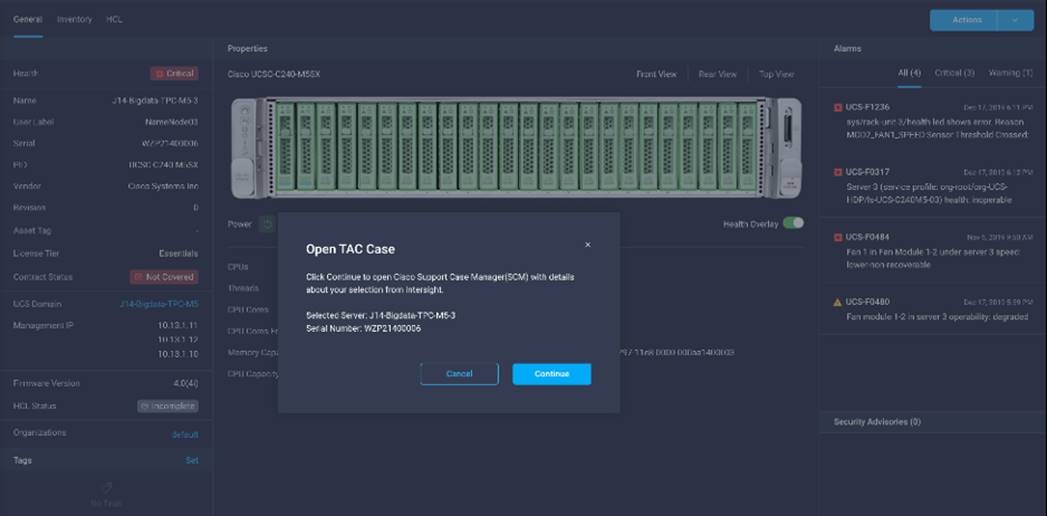
Step 3. Click Open TAC Case to launch the Cisco URL for the support case manager where associated service contracts for Server or Fabric Interconnect is displayed.
Step 4. Click Continue.
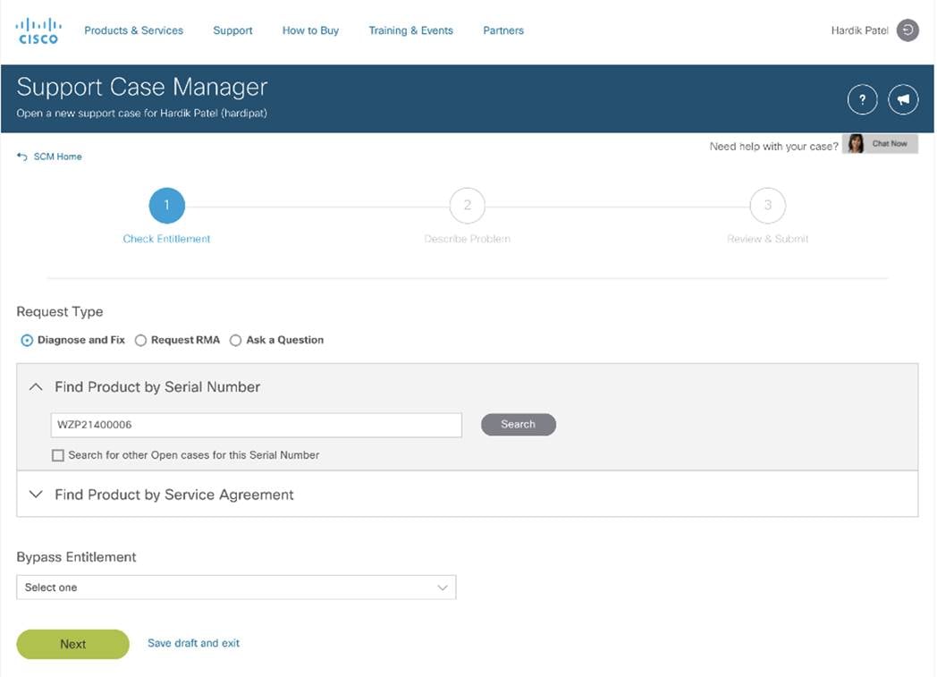
Step 5. Follow the procedure to Open TAC Case.
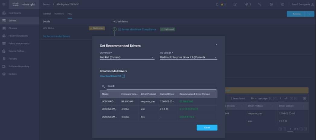
Cisco Intersight Integration for HCL
Cisco Intersight evaluates the compatibility of your Cisco UCS and HyperFlex systems to check if the hardware and software have been tested and validated by Cisco or Cisco partners. Cisco Intersight reports validation issues after checking the compatibility of the server model, processor, firmware, adapters, operating system, and drivers, and displays the compliance status with the Hardware Compatibility List (HCL).
You can use Cisco UCS Tools, a host utility vSphere Installation Bundle (VIB), or OS Discovery Tool, an open-source script to collect OS and driver information to evaluate HCL compliance.
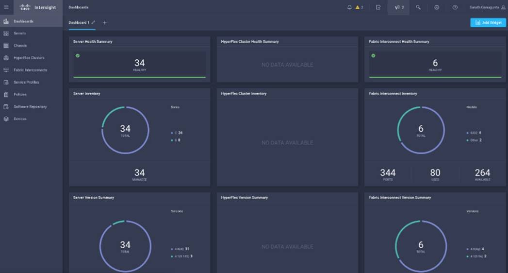
In Cisco Intersight, you can view the HCL compliance status in the dashboard (as a widget), the Servers table view, and the Server details page.
Note: For more information, go to: https://www.intersight.com/help/features#compliance_with_hardware_compatibility_list_(hcl)
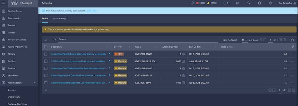
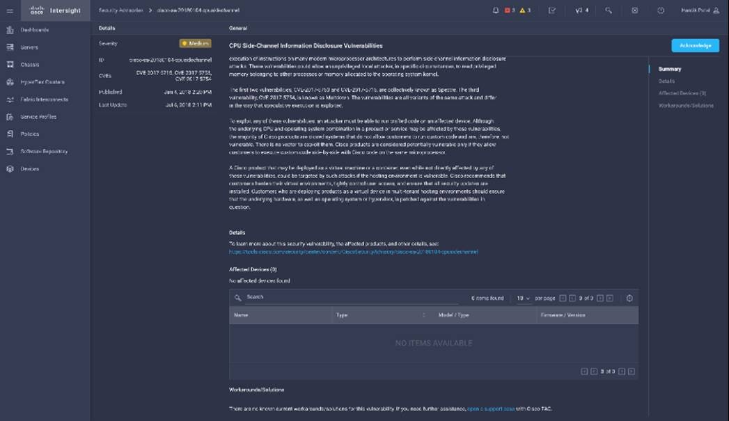
Cisco Intersight sources critical security advisories from the Cisco Security Advisory service to alert users about the endpoint devices that are impacted by the advisories and deferrals. These alerts are displayed as Advisories in Intersight. The Cisco Security Advisory service identifies and monitors and updates the status of the advisories to provide the latest information on the impacted devices, the severity of the advisory, the impacted products, and any available workarounds. If there are no known workarounds, you can open a support case with Cisco TAC for further assistance. A list of the security advisories is shown in Intersight under Advisories.
Cloudera Data Platform Private Cloud (CDP PvC) is the on-premises version of Cloudera Data Platform. CDP Private Cloud delivers powerful analytic, transactional, and machine learning workloads in a hybrid data platform, combining the agility and flexibility of public cloud with the control of the data center. With a choice of traditional as well as elastic analytics and scalable object storage, CDP Private Cloud modernizes traditional monolithic cluster deployments into a powerful and efficient platform.
An integral part of CDP Hybrid Cloud, CDP Private Cloud provides the first step for data center customers toward true data and workload mobility, managed from a single pane of glass and with consistent data security and governance across all clouds, public and private. CDP is an integrated data platform that is easy to deploy, manage, and use. By simplifying operations, CDP reduces the time to onboard new use cases across the organization.
With CDP Private Cloud, organizations benefit from:
● Unified Distribution: CDP offers rapid time to value through simplified provisioning of easy-to-use, self-service analytics enabling onboarding of new use cases at higher velocity.
● Hybrid & On-prem: Hybrid and multi-cloud experience, on-prem it offers best performance, cost, and security. It is designed for data centers with optimal infrastructure.
● Management: It provides consistent management and control points for deployments.
● Consistency: Security and governance policies can be configured once and applied across all data and workloads.
● Portability: Policies stickiness with data, even if it moves across all supported infrastructure.
● Improved cost efficiency with optimized resource utilization and the decoupling of compute and storage, lowering data center infrastructure costs up to 50%.
● Predictable performance thanks to workload isolation and perfectly managed multi-tenancy, eliminating the impact of spikes on critical workloads and resulting missed SLAs and SLOs.
Cloudera Data Platform Private Cloud Base (CDP PvC Base)
CDP Private Cloud Base is the on-premises version of Cloudera Data Platform. This new product combines the best of Cloudera Enterprise Data Hub and Hortonworks Data Platform Enterprise along with new features and enhancements across the stack. This unified distribution is a scalable and customizable platform where you can securely run many types of workloads.
CDP Private Cloud Base supports a variety of hybrid solutions where compute tasks are separated from data storage and where data can be accessed from remote clusters, including workloads created using CDP Private Cloud Data Services. This hybrid approach provides a foundation for containerized applications by managing storage, table schema, authentication, authorization, and governance.
CDP Private Cloud Base is comprised of a variety of components such as Apache HDFS, Apache Hive 3, Apache HBase, and Apache Impala, along with many other components for specialized workloads. You can select any combination of these services to create clusters that address your business requirements and workloads. Several pre-configured packages of services are also available for common workloads.
Cloudera Data Platform Private Cloud Data Services (CDP PvC DS)
Cloudera Data Platform (CDP) Private Cloud is the newest on-prem offering of CDP that brings many of the benefits of the public cloud deployments to the on-prem CDP deployments.
CDP Private Cloud provides a disaggregation of compute and storage and allows independent scaling of compute and storage clusters. Using containerized applications deployed on Kubernetes, CDP Private Cloud brings both agility and predictable performance to analytic applications. CDP Private Cloud gets unified security, governance, and metadata management through Cloudera Shared Data Experience (SDX), which is available on a CDP Private Cloud Base cluster.
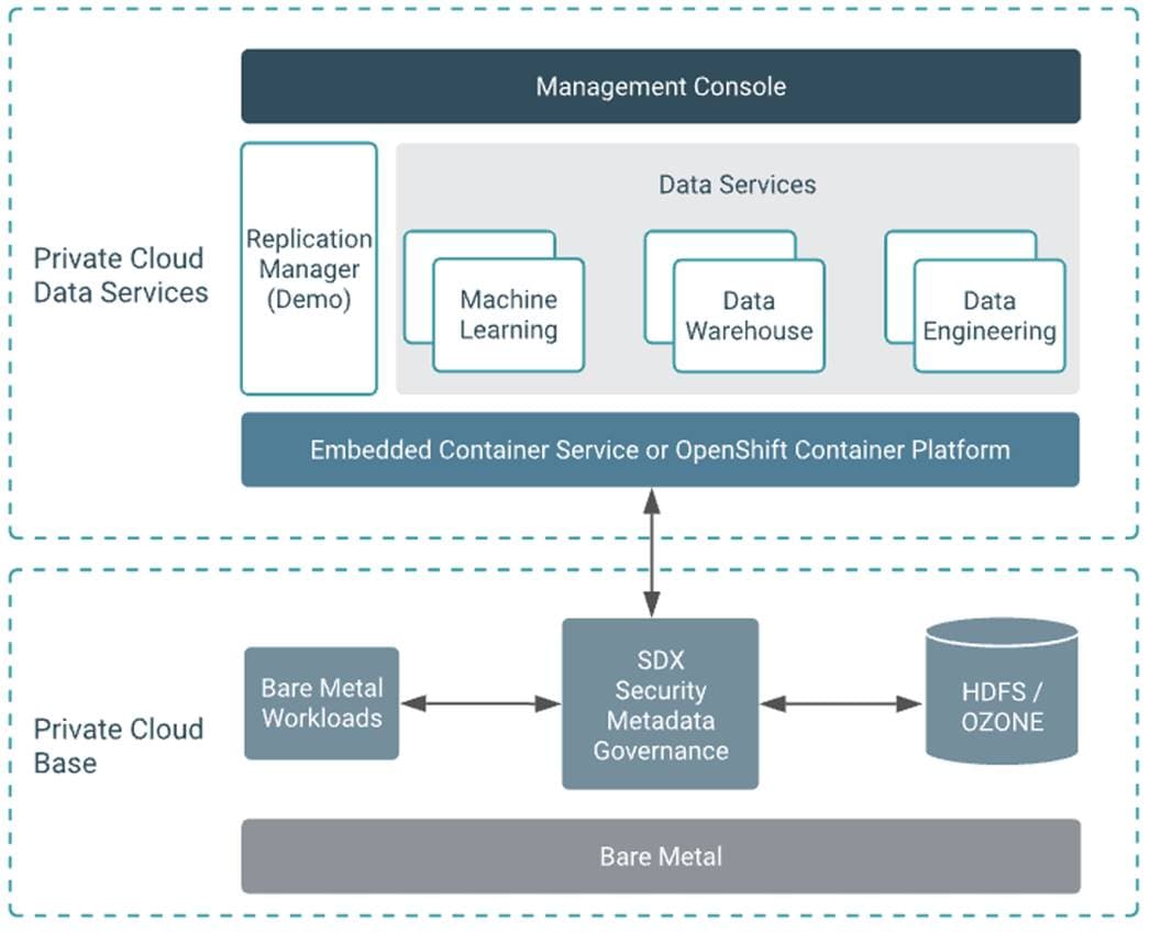
CDP Private Cloud users can rapidly provision and deploy Cloudera Data Engineering (CDE), Cloudera Data Warehousing (CDW) and Cloudera Machine Learning (CML) services through the Management Console, and easily scale them up or down as required.
A CDP Private Cloud deployment requires you to have a Private Cloud Base cluster and a RedHat OpenShift Kubernetes cluster. The OpenShift cluster is set up on a Bare Metal deployment. The Private Cloud deployment process involves configuring the Management Console on the OpenShift cluster, registering an environment by providing details of the Data Lake configured on the Base cluster, and then creating the workloads.
Cloudera Shared Data Experience (SDX)
SDX is a fundamental part of Cloudera Data Platform architecture, unlike other vendors’ bolt-on approaches to security and governance. Independent from compute and storage layers, SDX delivers an integrated set of security and governance technologies built on metadata and delivers persistent context across all analytics as well as public and private clouds. Consistent data context simplifies the delivery of data and analytics with a multi-tenant data access model that is defined once and seamlessly applied everywhere.
SDX reduces risk and operational costs by delivering consistent data context across deployments. IT can deploy fully secured and governed data lakes faster, giving more users access to more data, without compromise.
Key benefit and feature of SDX includes:
● Insightful metadata - Trusted, reusable data assets and efficient deployments need more than just technical and structural metadata. CDP’s Data Catalog provides a single pane of glass to administer and discover all data, profiled, and enhanced with rich metadata that includes the operational, social, and business context, and turns data into valuable information
● Powerful security - Eliminate business and security risks and ensure compliance by preventing unauthorized access to sensitive or restricted data across the platform with full auditing. SDX enables organizations to establish multi-tenant data access with ease through standardization and seamless enforcement of granular, dynamic, role- and attribute-based security policies on all clouds and data centers.
● Full encryption - Enjoy ultimate protection as a fundamental part of your CDP installation. Clusters are deployed and automatically configured to use Kerberos and for encrypted network traffic with Auto-TLS. Data at rest, both on-premises and in the cloud, is protected with enterprise-grade cryptography, supporting best practice tried and tested configurations
● Hybrid control - Meet the ever-changing business needs to balance performance, cost, and resilience. Deliver true infrastructure independence. SDX enables it all with the ability to move data, together with its context, as well as workloads between CDP deployments. Platform operational insight into aspects like workload performance deliver intelligent recommendations for optimal resource utilization
● Enterprise-grade governance - Prove compliance and manage the complete data lifecycle from the edge to AI and from ingestion to purge with data management across all analytics and deployments. Identify and manage sensitive data, and effectively address regulatory requirements with unified, platform-wide operations, including data classification, lineage, and modeling.
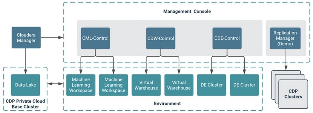
CDP Private Cloud Management Console
The Management Console is a service used by CDP administrators to manage environments, users, and services.
The Management Console allows you to:
● Enable user access to CDP Private Cloud Data Services, onboard and set up authentication for users, and determine access rights for the various users to the available resources.
● Register an environment, which represents the association of your user account with compute resources using which you can manage and provision workloads such as Data Warehouse and Machine Learning. When registering the environment, you must specify a Data Lake residing on the Private Cloud base cluster to provide security and governance for the workloads.
● View information about the resources consumed by the workloads for an environment.
● Collect diagnostic information from the services for troubleshooting purposes.
Figure 27 shows a basic architectural overview of the CDP Private Cloud Management Console.
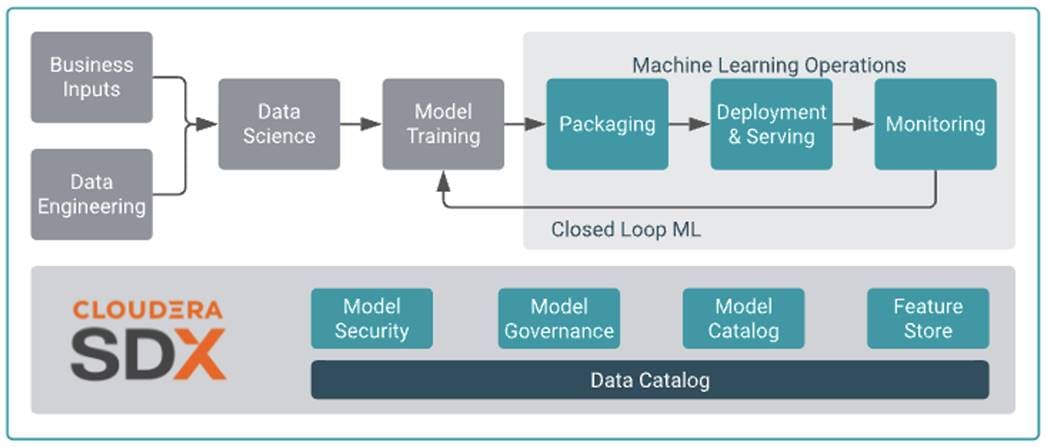
Cloudera Machine Learning (CML)
Cloudera Machine learning caters to data scientists to develop and operationalize ML models. From automating internal processes to optimizing the design, creation, and marketing processes behind virtually every product consumed, ML models have permeated almost every aspect of our work and personal lives. It has become one of the most critical capabilities for modern businesses to grow and stay competitive today.
Cloudera Machine Learning (CML) is Cloudera’s new cloud-native machine learning service, built for CDP. The CML service provisions clusters, also known as ML workspaces, which run natively on Kubernetes.
Each ML workspace enable teams of data scientists to develop, test, train, and ultimately deploy machine learning models for building predictive applications all on the data under management within the enterprise data cloud. ML workspaces are ephemeral, allowing you to create and delete them on-demand. ML workspaces support fully containerized execution of Python, R, Scala, and Spark workloads through flexible and extensible engines.
Cloudera Machine Learning covers the end-to-end machine learning workflow, enabling fully isolated and containerized workloads - including Python, R, and Spark-on-Kubernetes - for scale-out data engineering and machine learning with seamless distributed dependency management.
● Sessions enable Data Scientists to directly leverage the CPU, memory, and GPU compute available across the workspace, while also being directly connected to the data in the data lake.
● Experiments enable Data Scientists to run multiple variations of model training workloads, tracking the results of each Experiment to train the best possible Model.
● Models can be deployed in a matter of clicks, removing any roadblocks to production. They are served as REST endpoints in a high availability manner, with automated lineage building and metric tracking for MLOps purposes.
● Jobs can be used to orchestrate an entire end-to-end automated pipeline, including monitoring for model drift, and automatically kicking off model re-training and re-deployment as needed.
● Applications deliver interactive experiences for business users in a matter of clicks. Frameworks such as Flask and Shiny can be used in development of these Applications, while Cloudera Data Visualization is also available as a point-and-click interface for building these experiences.
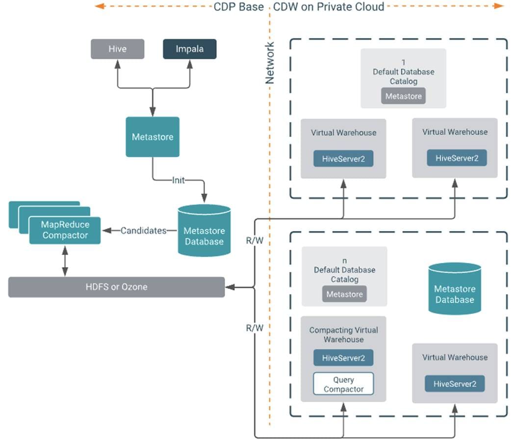
Cloudera Data Warehouse (CDW)
Data Warehouse is a CDP Private Cloud service for self-service creation of independent data warehouses and data marts that auto-scale up and down to meet your varying workload demands. The Data Warehouse service provides isolated compute instances for each data warehouse/mart, automatic optimization, and enables you to save costs while meeting SLAs. In the CDW Private Cloud service, your data is stored in HDFS in the base cluster. The service is composed of the following:
● Database Catalogs
A logical collection of metadata definitions for managed data with its associated data context. The data context is comprised of table and view definitions, transient user and workload contexts from the Virtual Warehouse, security permissions, and governance artifacts that support functions such as auditing. One Database Catalog can be queried by multiple Virtual Warehouses.
Database Catalogs are Hive MetaStore (HMS) instances and include references to the cloud storage where the data lives. An environment can have multiple Database Catalogs.
The default Database Catalog shares the HMS database with HMS in the base cluster. This enables you to access any objects or data sets created in the base clusters from CDW Virtual Warehouses and vice versa.
● Virtual Warehouses
An instance of compute resources that is equivalent to a cluster. A Virtual Warehouse provides access to the data in tables and views that correlate to a specific Database Catalog. Virtual Warehouses bind compute and storage by executing queries on tables and views that are accessible through the Database Catalog that they have been configured to access.
The Cloudera Data Warehouse service provides data warehouses and data marts that are:
● Automatically configured and isolated
● Optimized for your existing workloads when you move them to your private cloud
● Auto-scale up and down to meet your workloads' varying demands
● Auto-suspend and resume to allow optimal usage of resources
● Compliant with the security controls associated with your base cluster
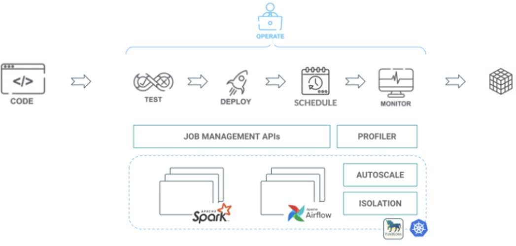
Cloudera Data Engineering (CDE)
Cloudera Data Engineering is a CDP Private Cloud service for data engineers to operationalize their data pipelines. which allows to create, manage, and schedule Apache Spark jobs without the overhead of creating and maintaining Spark clusters. Cloudera Data Engineering, define virtual clusters with a range of CPU and memory resources, and the cluster scales up and down as needed to run your Spark workloads.
The CDE service involves several components:
● Environment – A logical subset of your cloud provider account including a specific virtual network. For more information, see Environments.
● CDE Service – The long-running Kubernetes cluster and services that manage the virtual clusters. The CDE service must be enabled on an environment before you can create any virtual clusters.
● Virtual Cluster – An individual auto-scaling cluster with defined CPU and memory ranges. Virtual Clusters in CDE can be created and deleted on demand. Jobs are associated with clusters.
● Jobs – Application code along with defined configurations and resources. Jobs can be run on demand or scheduled. An individual job execution is called a job run.
● Resource – A defined collection of files such as a Python file or application JAR, dependencies, and any other reference files required for a job. A resource can be used by multiple jobs, and jobs can use multiple resources. The resource types supported by CDE are files and python-env.
● Job run – An individual job run.
Apache Ozone
Apache Ozone is a scalable, redundant, and distributed object store for Hadoop. Apart from scaling to billions of objects of varying sizes, Ozone can function effectively in containerized environments such as Kubernetes and YARN. Applications using frameworks like Apache Spark, YARN, and Hive work natively without any modifications. Apache Ozone is built on a highly available, replicated block storage layer called Hadoop Distributed Data Store (HDDS).
Apache Ozone consists of volumes, buckets, and keys:
● Volumes are similar to user accounts. Only administrators can create or delete volumes.
● Buckets are similar to directories. A bucket can contain any number of keys, but buckets cannot contain other buckets.
● Keys are similar to files. Each key is part of a bucket, which, in turn, belongs to a volume. Ozone stores data as keys inside these buckets.
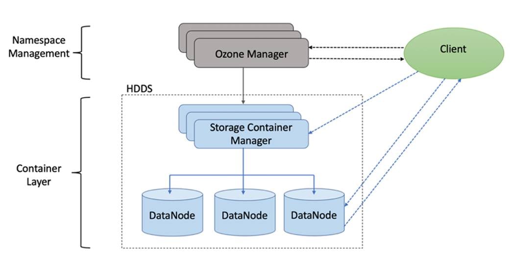
When a key is written to Apache Ozone, the associated data is stored on the Data Nodes in chunks called blocks. Therefore, each key is associated with one or more blocks. Within the Data Nodes, a series of unrelated blocks is stored in a container, allowing many blocks to be managed as a single entity.
Apache Ozone separates management of namespaces and storage, helping it to scale effectively. Apache Ozone Manager manages the namespaces while Storage Container Manager handles the containers.
Apache Ozone is a distributed key-value store that can manage both small and large files alike. While HDFS provides POSIX-like semantics, Apache Ozone looks and behaves like an Object Store.
Apache Ozone has the following cost savings and benefits due to storage consolidation:
● Lower Infrastructure cost
● Lower software licensing and support cost
● Lower lab footprint
● Newer additional use cases with support for HDFS and S3 and billions of objects supporting both large and small files in a similar fashion.
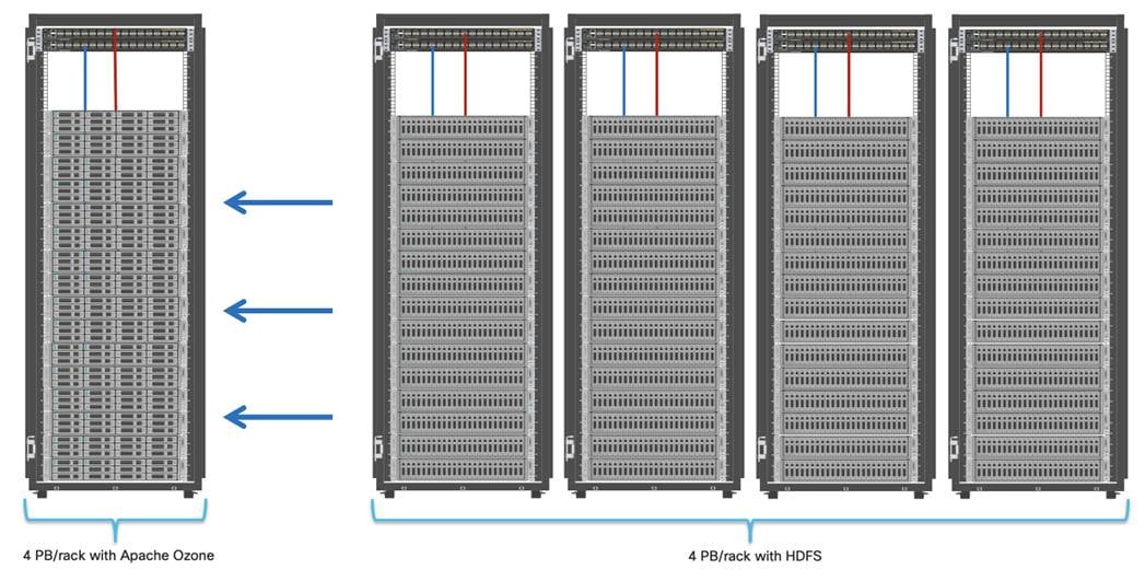
For more information about Apache Ozone, go to: https://blog.cloudera.com/apache-ozone-and-dense-data-nodes/
Persistent Storage for Kubernetes
Workloads deployed in containers and orchestrated via Kubernetes(K8) are either stateless or stateful. By default, K8 workloads are stateless. Stateless applications don’t persist, which means it uses temporary storage provided within K8 and destroys once the application or pod is terminated. That’s why we call containers are ephemeral in nature, data associated with containers can be lost once the container is terminated or accidentally crashed. Furthermore, data can’t be shared among other containers either.
For stateful application, persistent storage is the first “must have” requirement. Kubernetes supports various persistent storage solutions that help addressing this problem and support stateful workloads in a containerized environment. Kubernetes introduces the concept of Persistent Volumes, which exist independently of containers, survive even after containers shut down, and can be requested and consumed by containerized workloads.
There are various methods of providing persistent storage to containers. However, in this reference design, Red Hat OpenShift Container Storage is used to provide persistent volume for Cloudera Private Cloud control plane and Cloudera Machine Learning backed by Red Hat OpenShift Container Platform.
Red Hat OpenShift Container Storage (OCS)
OCS is software-defined storage integrated with and optimized for Red Hat OpenShift Container Platform. OpenShift Container Storage 4.8 is built on Red Hat Ceph® Storage, Rook, and NooBaa to provide container native storage services that support block, file, and object services.
Leveraging the Kubernetes Operator framework, OpenShift Container Storage (OCS) automates a lot of the complexity involved in providing cloud native storage for OpenShift. OCS integrates deeply into cloud native environments by providing a seamless experience for scheduling, lifecycle management, resource management, security, monitoring, and user experience of the storage resources.
To deploy OpenShift Container Storage, the administrator can go to the OpenShift Administrator Console and navigate to the “Operator Hub” to find the OpenShift Container Storage Operator
OpenShift Container Storage may be used to provide storage for several workloads:
● Block storage for application development and testing environments that include databases, document stores, and messaging systems.
● File storage for CI/CD build environments, web application storage, and for ingest and aggregation of datasets for machine learning.
● Multi-cloud object storage for CI/CD builds artifacts, origin storage, data archives, and pre-trained machine learning models that are ready for serving.
To enable user provisioning of storage, OCS provides storage classes that are ready-to-use when OCS is deployed.
OpenShift Container Storage uses the following operators:
● The OpenShift Container Storage (OCS) Operator
A meta-operator that codifies and enforces the recommendations and requirements of a supported Red Hat OpenShift Container Storage deployment by drawing on other operators in specific, tested ways. This operator provides the storage cluster resource that wraps resources provided by the Rook-Ceph and NooBaa operators.
● The Rook-Ceph Operator
This operator automates the packaging, deployment, management, upgrading, and scaling of persistent storage provided to container applications, and infrastructure services provided to OpenShift Container Platform. It provides the Ceph cluster resource, which manages the pods that host services such as the Object Storage Daemons (OSDs), monitors, and the metadata server for the Ceph file system.
● The NooBaa Operator
This operator provides the Multi-cloud Object Gateway, an S3 compatible object store service that allows resource access across multiple cloud environments.
This chapter contains the following:
● Cloudera Data Platform Private Cloud Requirements
● Host OS Firewall for Required Ports
● Cloudera Private Cloud Storage Requirements
● Consistent Linux Storage Device Naming and Order
● CDP PvC DS Storage, Memory, and Cores
● Persistent Storage using Local Volumes
This CVD was designed with the following:
● 3 x Cisco UCS X210c compute node with RedHat OpenShift Container Platform Master nodes
● 5 x Cisco UCS X210c compute node with RedHat OpenShift Container Platform worker nodes
● 4 x Cisco UCS X210c compute node and 4 x Cisco UCS X440p PCIe node hosting 2 x NVIDIA A100 GPU per node with RedHat OpenShift Container Platform worker nodes
● Cloudera Data Platform Private Cloud Data Services running on the RedHat OpenShift Container Platform
● 1 x Cisco UCS C240 M6 bootstrap node for RedHat OpenShift Container Platform
● 1 x Cisco UCS C240 M6 running HA Proxy
● Cloudera Data Platform Private Cloud Base (the data lake) which is not detailed in this CVD but is extensively explained in the CVDs published here: http://www.cisco.com/go/bigdata_design.
Table 3 lists the required physical components and hardware.
Table 3. CDIP with CDP PvC DS System Components
| Component |
Hardware |
| Fabric Interconnects |
2 x Cisco UCS 6454 Fabric Interconnects |
| Servers |
Cisco UCS 9508 chassis - Cisco UCS X210c compute node - Cisco UCS X440p PCIe node |
Table 4 lists the software components and the versions required for a single cluster of the Cohesity Helios Platform running in Cisco UCS, as tested, and validated in this document.
Table 4. Software Components and Hardware
| Layer |
Component |
Version or Release |
| Compute |
Cisco UCS X210C |
5.0(2b) |
| Network
|
Cisco UCS Fabric Interconnect 6454 |
9.3(5)I42(2a) |
| Cisco UCS VIC 14425 4x25G mLOM for X Compute Node |
5.2(2b) |
|
| UCS 9108-25G IFM for X9508 chassis |
4.2(2a) |
|
| UCS 9416 X-Fabric module for 9508 chassis |
|
|
| Software |
Cloudera Data Platform Private Cloud Base |
7.1.7 SP1 |
| Cloudera Manager |
7.6.5 |
|
| Cloudera Data Platform Private Cloud Data Services |
1.4.0 |
|
| Postgres |
12.11 |
|
| Hadoop (Includes YARN and HDFS) |
3.1.1 |
|
| Spark |
2.4.7 |
|
| Red Hat Enterprise Linux Server (CDP Private Cloud Base) |
8.4 |
|
| Red Hat CoreOS (CDP Private Cloud Data Services) |
4.8.14 |
|
| Red Hat OpenShift Container Platform/Kubernetes |
stable-4.8 channel |
|
| OpenShift Container Storage |
4.8.14 |
Note: The Cisco latest drivers can be downloaded here: https://software.cisco.com/download/home.
Note: Please check the CDP PvC requirements and supported versions for information about hardware, operating system, and database requirements, as well as product compatibility matrices, here: https://supportmatrix.cloudera.com/ and here: https://docs.cloudera.com/cdp-private-cloud-upgrade/latest/release-guide/topics/cdpdc-requirements-supported-versions.html
Note: CDP PvC DS version 1.4.0 supports CentOS 8.4, 7.9, Red Hat Enterprise Linux 8.4. 7.9, Oracle Linux 7.9, and CentOS 8.2 (CDW only). For complete list of supported version visit, https://docs.cloudera.com/cdp-private-cloud-data-services/1.4.0/installation-ecs/topics/cdppvc-installation-ecs-software-requirements.html
Physical Topology
Cisco UCS X-Series 9508 chassis with a pair of X9108 intelligent fabric module and a pair of XFM9416 per chassis consisting of 12 x X210C compute node and 4 x X440p PCIe node hosted in two chassis connected to a pair of Cisco UCS 6400 series Fabric Interconnects.
Note: Please contact your Cisco representative for country-specific information.
Figure 34 shows the logical topology
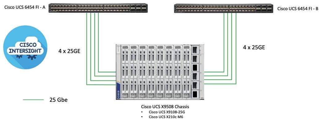
● Cisco UCS 6454 Fabric Interconnects provide the chassis and network connectivity.
● The Cisco UCS X9508 Chassis connects to fabric interconnects using Cisco UCSX 9108-25G Intelligent Fabric Modules (IFMs), where four or eight 25 Gigabit Ethernet ports are used on each IFM to connect to the appropriate FI.
● Cisco UCS X210c M6 Compute Nodes contain fourth-generation Cisco 14425 virtual interface cards.
There are many platform dependencies to enable Cloudera Data Platform Private Cloud Data Services running on RedHat OpenShift Container Platform. The containers need to access data stored on HDFS in Cloudera Data Platform Private Cloud Base in a fully secure manner.
The following are the prerequisites needed to enable this solution:
● Network requirements
● Security requirements
● Operating System requirements
● RedHat OpenShift Container Platform requirements
● Cloudera Private Cloud persistence storage requirements
● Cloudera Data Warehouse local storage requirements
● NFS requirements for Cloudera Machine Learning workspaces
● Cloudera requirements
Network Requirements
Cloudera Private Cloud Base cluster that houses HDFS storage and Cloudera Private Cloud compute-only clusters should be reachable with no more than a 3:1 oversubscription to be able to read from and write to the base HDFS cluster. The recommended network architecture is Spine-Leaf between the spine and leaf switches. Additional routing hops should be avoided in production and ideally both HDFS/Ozone storage and Cloudera Private Cloud Data Services are on the same network.
For more information, go to: https://docs.cloudera.com/cdp-private-cloud-upgrade/latest/release-guide/topics/cdpdc-networking-security-requirements.html
Both CDP Private Cloud Base and CDP Private Cloud Data Services cluster should have their time synched with the NTP Clock time from same the NTP source. Also make sure, Active Directory server where Kerberos is setup for data lake and for other services must also be synced with same NTP source.
Note: DNS is required for this solution. It is the requirement for setting up Active Directory, Kerberos, Cloudera Manager authentication, and OpenShift.
DNS must have the following:
● Each host whether Cloudera Manger or Red Hat OpenShift must be accessible via DNS.
● DNS must be configured for forward AND reverse for each host. Reverse is required for Kerberos authentication to the Base Cloudera cluster.
● Cloudera Manager host must be able to resolve hostname of Red Hat OpenShift ingress/route via DNS of wildcard entry to load balancer of OpenShift Container Platform.
● Service DNS entry must be configured for ETCD cluster. For each control plane machine, OpenShift Container Platform also requires an SRV DNS record for etcd server on that machine with priority 0, weight 10 and port 2380.
A wildcard DNS entry is required for resolving the ingress/route for applications.
Cloudera Data Platform Private Cloud Requirements
The cluster must be configured with JDK 11, JDK8 is not supported. You can use Oracle, OpenJDK 11.04, or higher. JAVA 11 is a JKS requirement and must be met. In this CVD we used Oracle JDK 11.0.13.
Kerberos must be configured using an Active Directory (AD) or MIT KDC. The Kerberos Key Distribution Center (KDC) will use the domain’s Active Directory service database as its account database. An Active Directory server is recommended for default Kerberos implementations and will be used in the validation of this solution. Kerberos will be enabled for all services in the cluster.
Note: Red Hat IPA/Identity Management is currently not supported.
Database Requirements
Cloudera Manager and Runtime come packaged with an embedded PostgreSQL database for use in non-production environments. The embedded PostgreSQL database is not supported in production environments. For production environments, you must configure your cluster to use dedicated external databases.
For detailed information about supported database visit: https://supportmatrix.cloudera.com/
Note: Cloudera Data Warehouse (CDW) only supports PostgreSQL database version 12. PostgreSQL database versions 10 and 11 are not supported. PostgreSQL must be configured with SSL enabled and uses the same keystore containing an embedded certificate as Ranger and Atlas uses.
Configure Cloudera Manager with TLS/SSL
TLS/SSL provides privacy and data integrity between applications communicating over a network by encrypting the packets transmitted between endpoints (ports on a host, for example). Configuring TLS/SSL for any system typically involves creating a private key and public key for use by server and client processes to negotiate an encrypted connection at runtime. In addition, TLS/SSL can use certificates to verify the trustworthiness of keys presented during the negotiation to prevent spoofing and mitigate other potential security issues.
Setting up Cloudera clusters to use TLS/SSL requires creating private key, public key, and storing these securely in a keystore, among other tasks. Although adding a certificate to the keystore may be the last task in the process, the lead time required to obtain a certificate depends on the type of certificate you plan to use for the cluster.
For detailed information on encrypting data in transit, go to: https://docs.cloudera.com/cdp-private-cloud-base/7.1.7/security-encrypting-data-in-transit/topics/cm-security-guide-ssl-certs.html
The Auto-TLS feature automates all the steps required to enable TLS encryption at a cluster level. Using Auto-TLS, you can let Cloudera manage the Certificate Authority (CA) for all the certificates in the cluster or use the company’s existing CA. In most cases, all the necessary steps can be enabled easily via the Cloudera Manager UI. This feature automates the following processes when Cloudera Manager is used as a Certificate Authority:
● Creates the root Certificate Authority or a Certificate Signing Request (CSR) for creating an intermediate Certificate Authority to be signed by company’s existing Certificate Authority (CA)
● Generates the CSRs for hosts and signs them
Configuring TLS Encryption for Cloudera Manager Using Auto-TLS for detailed information: https://docs.cloudera.com/cdp-private-cloud-base/7.1.7/security-encrypting-data-in-transit/topics/cm-security-how-to-configure-cm-tls.html
Manually Configuring TLS Encryption for Cloudera Manager for detailed information: https://docs.cloudera.com/cdp-private-cloud-base/7.1.7/security-encrypting-data-in-transit/topics/cm-security-how-to-configure-cm-tls.html
TLS uses JKS-format (Java KeyStore)
Cloudera Manager Server, Cloudera Management Service, and many other CDP services use JKS formatted key-stores and certificates. Java 11 is required for JKS.
Licensing Requirements
The cluster must be setup with a license with entitlements for installing Cloudera Private Cloud. 60 days evaluation license for Cloudera Data Platform Private Cloud Base does not allow you to set up CDP Private Cloud Data Services.
Cloudera Data Platform Private Cloud Data Services version 1.4.0 requires Cloudera Manager 7.6.5 and Cloudera Data Platform Private Cloud Base 7.1.7 and above, which together comprise the on-premises version of CDP.
Required Services
The following minimum services must be configured and setup in Data Lake for private cloud registration process:
● HDFS, Ozone, Hive Metastore, Ranger, and Atlas.
● There are other dependent services such as Solr for Ranger and HBase and Kafka for Atlas that must be configured.
● All services within the cluster must be in good health. Otherwise, environment registration for CDP PvC DS will fail.
Dedicated Red Hat OpenShift Cluster
Currently, Cloudera Private Cloud Data Services requires a Red Hat OpenShift Container Platform or Embedded Container Service cluster fully dedicated only to Cloudera Private Cloud. In future releases, it is expected to be supported on shared RedHat OpenShift Container Platform.
Note: For CDP Private Cloud Data Services, Red Hat OpenShift Container Platform should only contain worker nodes with CoreOS. RHOCP however supports to have worker nodes running on RHEL, but it is currently not supported for CDP Private cloud.
Red Hat OpenShift Container Platform Requirements
There are two approaches for OCP deployment:
● Installer Provisioned Infrastructure (IPI)
● User Provisioned Infrastructure (UPI)
To learn more about these installation types, please refer to the Red Hat documentation: https://docs.openshift.com/container-platform/4.8/installing/installing_bare_metal/installing-bare-metal.html
Note: This solution uses UPI to deploy RedHat OpenShift Container Platform.
Air-gapped Installations
If air gapped from the internet, the K8s cluster needs an Image repository that is reachable. Registries solutions known to work include docker-distribution and Artifactory. Registries not known to work are Quay and RH internal image reg.
Load Balancer – HAproxy
Load Balancer (HA-Proxy) must allow non-terminating HTTPS and in one case "websockets" via port 80 (required for CML).
HA proxy is must and must have good network connectivity. It load balances all master (control traffic), etcd traffic and wild card * app traffic. Port 80 and 443 should not be occupied by any http service running on this node.
Note: For this CVD, we used HAproxy load balancer and set it up in RHEL. It is recommended to use external load balancer for production grade setup. Load balancer exists in some form or the other in almost all enterprise networks. If planning to use HAproxy as a load balancer, implement high availability with keep-alive VIP.
DHCP (Optional)
DHCP is optional, however, DHCP is recommended for large scale deployment to manage the machines for the cluster long-term. In this reference architecture, DHCP is not used. It is based on setting up static IP addresses for RHOCP nodes.
Note: If DHCP is used, make sure DHCP server is configured to provide persistent IP addresses and host names to the cluster machines.
Host OS Firewall for Required Ports
Host and HAproxy firewall must be configured for all required ports are outlined in Red Hat OpenShift 4.5 documentation found here: https://docs.openshift.com/container-platform/4.8/installing/installing_bare_metal/installing-bare-metal-network-customizations.html
Custom service account names are not allowed. You must use default service names for example, hdfs, hive, and so on.
Current Support
Currently, CDP PvC Data Services 1.4.0 supports OpenShift Container Platform 4.7.x or 4.8.x or Embedded Container Service (ECS) which manages compute infrastructure and ease of deployment for the data services.
Note: This CVD highlights RHOCP 4.8.29 (stable channel) installation for CDP PvC DS deployment. Future CVD will cover detailed step by step guide for ECS.
For detailed requirement on CDP PvC DS with OpenShift please visit: https://docs.cloudera.com/cdp-private-cloud-data-services/1.4.0/installation/topics/cdppvc-installation-overview.html
For detailed requirement on CDP PvC DS with ECS please visit: https://docs.cloudera.com/cdp-private-cloud-data-services/1.4.0/installation-ecs/topics/cdppvc-installation-ecs-overview.html
CDP PvC DS deployment considerations details: https://docs.cloudera.com/cdp-private-cloud-data-services/1.4.0/installation-ecs/topics/cdppvc-installation-ecs-overview.html
Cloudera Private Cloud Storage Requirements
Persistent Volume Storage is a requirement and should be configured in Red Hat OpenShift. Cloudera Private Cloud has specific storage requirement for each of the following components:
● Cloudera Data Platform Private Cloud control plane
● Cloudera Machine Learning (CML)
● Cloudera Data Warehouse (CDW)
● Cloudera Data Engineering (CDE)
Consistent Linux Storage Device Naming and Order
Linux storage device naming should be consistent across reboot. This is the requirement for utilizing Linux disk devices to be configured for persistent storage. Cisco UCS offers configuring storage profile and this can be achieved easily through storage profiles configuration. Use of storage profile to create disk group for each disk (slot number) and add those group in the profile. Verify LUN-ID in server storage tab of server profile for verification.
Hardware RAID 1 will be configured for boot disk in all OpenShift nodes. OpenShift nodes will be deployed on Red Hat CoreOS installed master and worker nodes, single boot device name will be present during the install and this device will be configured with two M.2 SSDs RAID-1 in server’s profile.
Block Storage is provisioned in the form of Persistent Volumes (PV's). Rook Ceph, Portworx and OCS know to work.
Note: This CVD uses Ceph for persistence volume. The "Default Class" attribute must be set to "true" on Block Storage provider's Storage Class for Private Cloud deployment.
Note: Do not use CephFS as it is not yet supported. CephFS support is planned for a future release.
CDP PvC DS Storage, Memory, and Cores
The exact amount of storage classified as block or filesystem storage will depend on the specific workloads (Machine Learning or Data Warehouse) and how they are used:
● Data Warehousing will require minimum of 16 cores, 128 GB of memory, and 600 GB of locally attached storage, with 100 GB of persistent volume storage on filesystem mounts, per executor. 32+ cores (enabled with Hyper-Threading) and 384GB of RAM is recommended.
● Machine learning requirements on CPU, memory, and storage largely depend on the nature of your machine learning jobs; 4TB of persistent volume block storage is required per Machine Learning Workspace instance for storing different kinds of metadata related to workspace configuration. Additionally, Machine Learning requires access to NFS storage routable from all pods running in the OpenShift cluster.
● Monitoring uses a large Prometheus instance to scrape workloads. Disk usage depends on the scale of the workloads. Cloudera recommends 60 GB.
Table 5. Cloudera Private Cloud Data Service - Storage Requirement for CDE, CML and CDW
| CDP PvC DS |
Storage Type |
Required Storage |
Purpose |
| CDE |
NFS |
500GB per Virtual Cluster in internal NFS |
Stores all information related to virtual clusters |
| CDW |
Local |
110 GB per executor in LITE mode and 620 GB per executor in FULL mode |
Used for caching |
| Control Plane |
NFS |
118 GB total if using an External Database, 318 GB total if using the Embedded Database |
Storage for ECS infrastructure including Fluentd logging, Prometheus monitoring, and Vault. Backing storage for an embedded DB for control plane configuration purpose, if applicable |
| CML |
NFS |
1 TB per workspace (depends on size of ML user files) |
Stores all information. For ML user project files |
| Monitoring App |
NFS |
30 GB + (Environment count x 100 GB) |
Stores metrics collected by Prometheus. |
Note: When you add memory and storage, it is very important that you add it in the increments stated:
- increments of 128 GB of memory
- increments of 620 GB of locally attached SSD/NVMe storage
- increments of 110 GB (in 5 chunks of 20 GB each) of persistent volume storage
Note: Kubernetes only utilizes the memory and storage in the above increments. If you add memory or storage that is not in the above increments, the memory and storage that exceeds these increments is not used for executor pods. Instead, the extra memory and storage can be used by other pods that require fewer resources.
For example, if you add 200 GB of memory, only 128 GB is used by the executor pods. If you add 2 TB of locally attached storage, only 1.8 TB is used by the executor pods.
Cloudera Machine Learning (CML) and Cloudera Data Engineering requires NFS. An internal user-space NFS server can be deployed into the cluster which serves a block storage device (persistent volume) managed by the cluster’s software defined storage (SDS) system, such as Ceph, Portworx, and so on. This is the recommended option for CML and CDE in Private Cloud.
Note: The NFS storage should be used only for storing project files and folders, and not for any other CML data, such as PostgreSQL database, and livelog.
Note: The CML does not support shared volumes, such as Ceph shared volumes, for storing project files.
Note: Review CDP Private Cloud Data Services storage requirements for more information: https://docs.cloudera.com/cdp-private-cloud-data-services/1.4.0/installation/topics/cdppvc-installation-storage-requirements-ocp.html
Persistent Storage using Local Volumes
Cloudera's Data Warehouse (CDW) requires local storage for purposes of query cache, in addition to Block persistent volumes. OpenShift Container Platform can be provisioned with persistent storage by using local volumes. Local persistent volumes allow you to access local storage devices, such as a disk or partition, by using the standard PVC interface. In production, this should be SSD/NVMe device local to each worker. Non-prod could use spinning media.
Cisco UCS Install and Configure
This chapter contains the following:
This section details the Cisco Intersight deployed Cisco UCS X210C M6 compute node configuration with Cisco UCS 9508 chassis connected to Cisco UCS Fabric Interconnect 6454 as part of the infrastructure build out. The racking, power, and installation of the Cisco UCS Rack Server for Cloudera Private Cloud Base can be found at Cisco Data Intelligence Platform design zone page. For detailed installation information, refer to the Cisco Intersight Managed Mode Configuration Guide.
This document assumes you are using Cisco Data Intelligence Platform with Cloudera Data Platform Private Cloud Base as outlined in the previously published at Design Zone for Big Data and Analytics which describes the steps to deploy Cisco UCS server domain via Cisco UCS Manager or Cisco Intersight Managed with CDP PvC Base.
Install Cisco UCS
This subject contains the following procedures:
● Claim a Cisco UCS Fabric Interconnect in the Cisco Intersight Platform
● Configure Cisco Intersight Pools and Policies
● Cisco Intersight Storage Policy Creation
Cisco Intersight Managed Mode standardizes policy and operation management for Cisco UCS X-Series. The compute nodes in Cisco UCS X-Series are configured using server profiles defined in Cisco Intersight. These server profiles derive all the server characteristics from various policies and templates. At a high level, configuring Cisco UCS using Intersight Managed Mode consists of the steps shown in Figure 35.
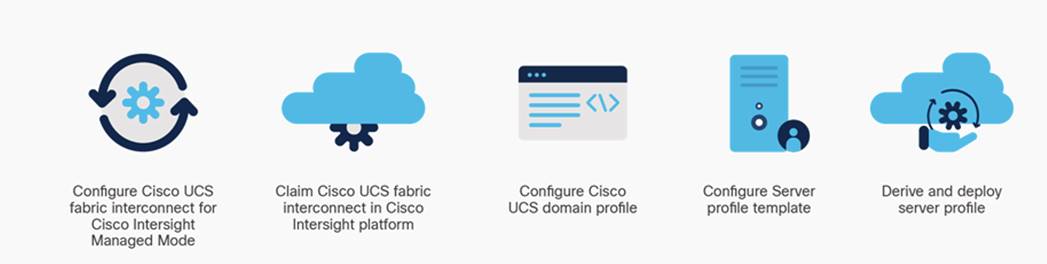
Procedure 1. Claim a Cisco UCS Fabric Interconnect in the Cisco Intersight Platform
Note: Cisco UCS Fabric Interconnect (FI) must be set up in Intersight Managed Mode (IMM) for configuring the Cisco UCS X-Series system. Figure 36 shows the dialog during initial configuration of Cisco UCS FIs for setting up IMM.
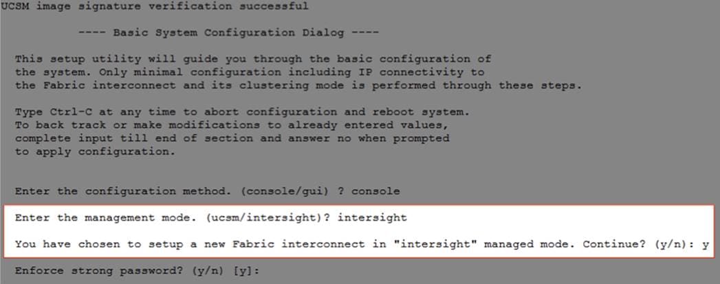
Note: After setting up the Cisco UCS fabric interconnect for Cisco Intersight Managed Mode, FIs can be claimed to a new or an existing Cisco Intersight account. When a Cisco UCS fabric interconnect is successfully added to the Cisco Intersight platform, all subsequent configuration steps are completed in the Cisco Intersight portal.
Step 1. To claim FI in IMM node, go to Targets > Claim a New Target.
Step 2. Select Cisco UCS Domain (Intersight Managed)
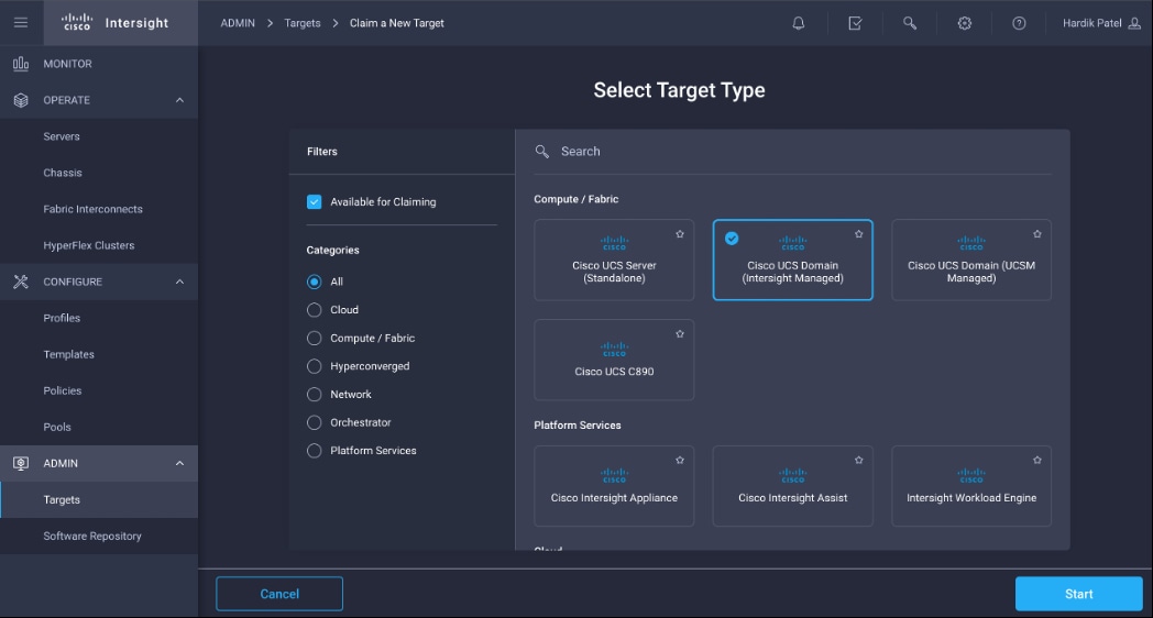
Step 3. Enter Device ID and Claim Code from one of the FI to be claimed. Click Claim.
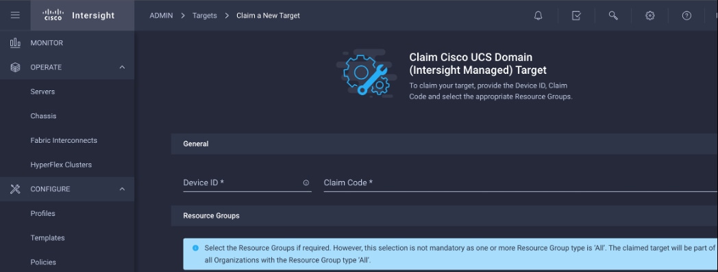
Step 4. Review the newly claimed Cisco UCS Domain.
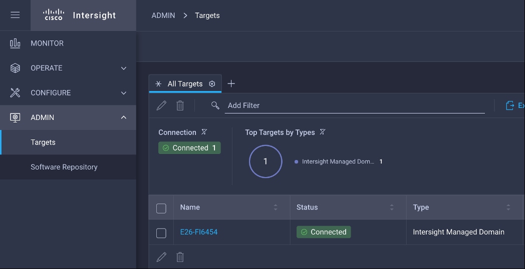
Step 5. You can verify whether a Cisco UCS fabric interconnect is in Cisco UCS Manager managed mode or Cisco Intersight Managed Mode by clicking on the fabric interconnect name and looking at the detailed information screen for the FI, as shown below:
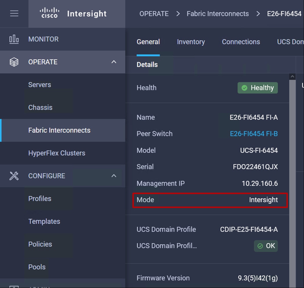
Procedure 2. Configure Cisco Intersight Pools and Policies
Note: Cisco Intersight requires different pools and policies which can be created at the time of profile creation or can be pre-populated and attached to the profile.
Step 1. To create the required set of pools, go to Configure > Pools. Click Create Pool, select type of pool creation and provide a range for the pool creation.
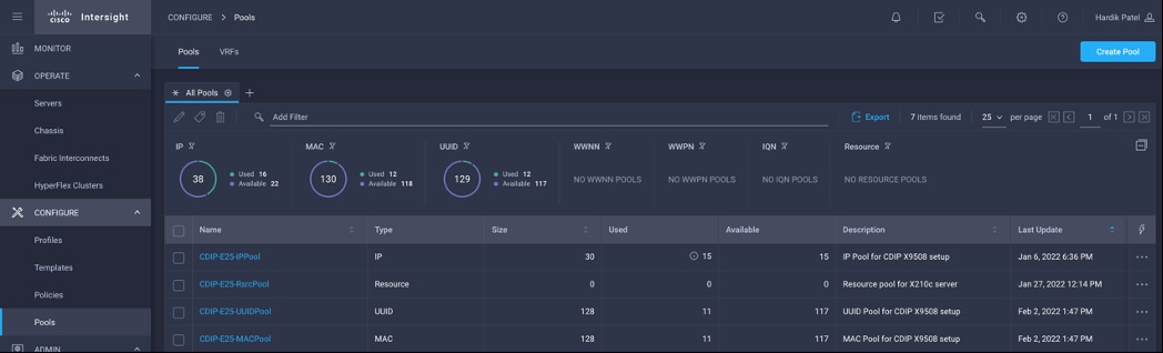
Step 2. To create the required set of policies, go to Configure > Policies. Click Create Policy.
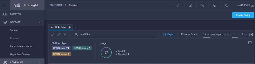
Step 3. Create policies for UCS Domain, UCS Chassis and UCS Server.
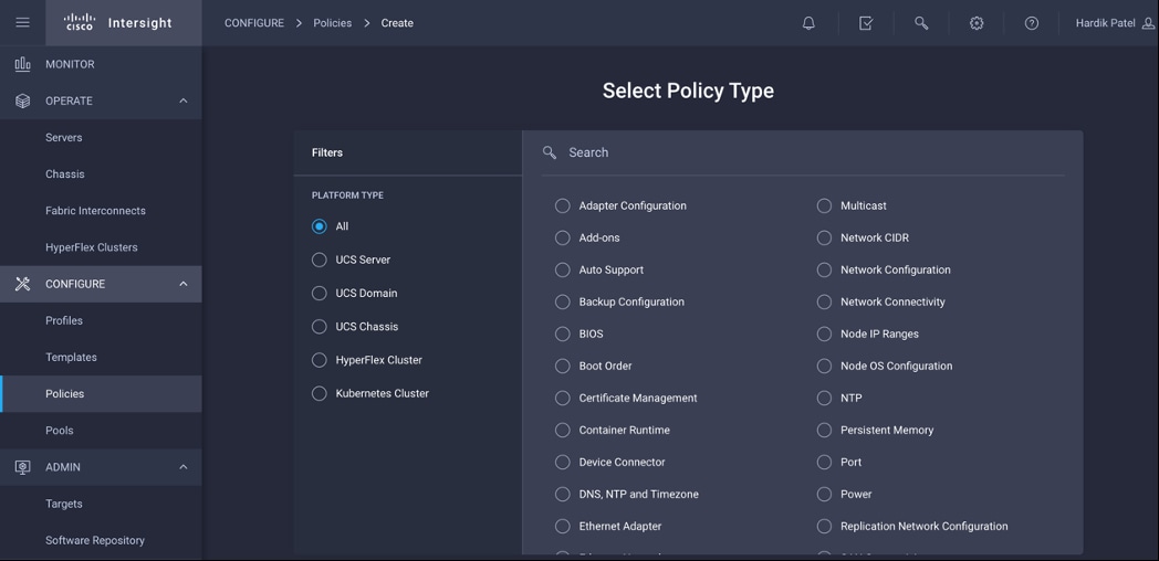
Cisco UCS Domain Profile
A Cisco UCS domain profile configures a pair of fabric interconnect through reusable policies, allows configuration of the ports and port channels, and configures the VLANs to be used in the network. It defines the characteristics of and configures the ports on the fabric interconnects. One Cisco UCS domain profile can be assigned to one fabric interconnect domain, and the Cisco Intersight platform supports the attachment of one port policy per Cisco UCS domain profile.
Some of the characteristics of the Cisco UCS domain profile environment are:
● A single domain profile is created for the pair of Cisco UCS fabric interconnects.
● Unique port policies are defined for the two fabric interconnects.
● The VLAN configuration policy is common to the fabric interconnect pair because both fabric interconnects are configured for same set of VLANs.
● The Network Time Protocol (NTP), network connectivity, and system Quality-of-Service (QoS) policies are common to the fabric interconnect pair.
After the Cisco UCS domain profile has been successfully created and deployed, the policies including the port policies are pushed to Cisco UCS fabric interconnects. Cisco UCS domain profile can easily be cloned to install additional Cisco UCS systems. When cloning the UCS domain profile, the new UCS domains utilize the existing policies for consistent deployment of additional Cisco UCS systems at scale.
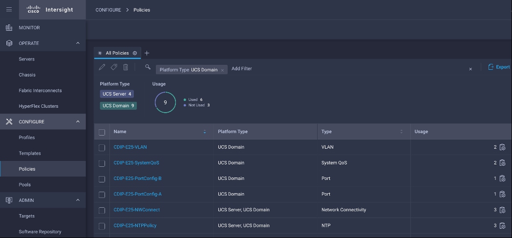
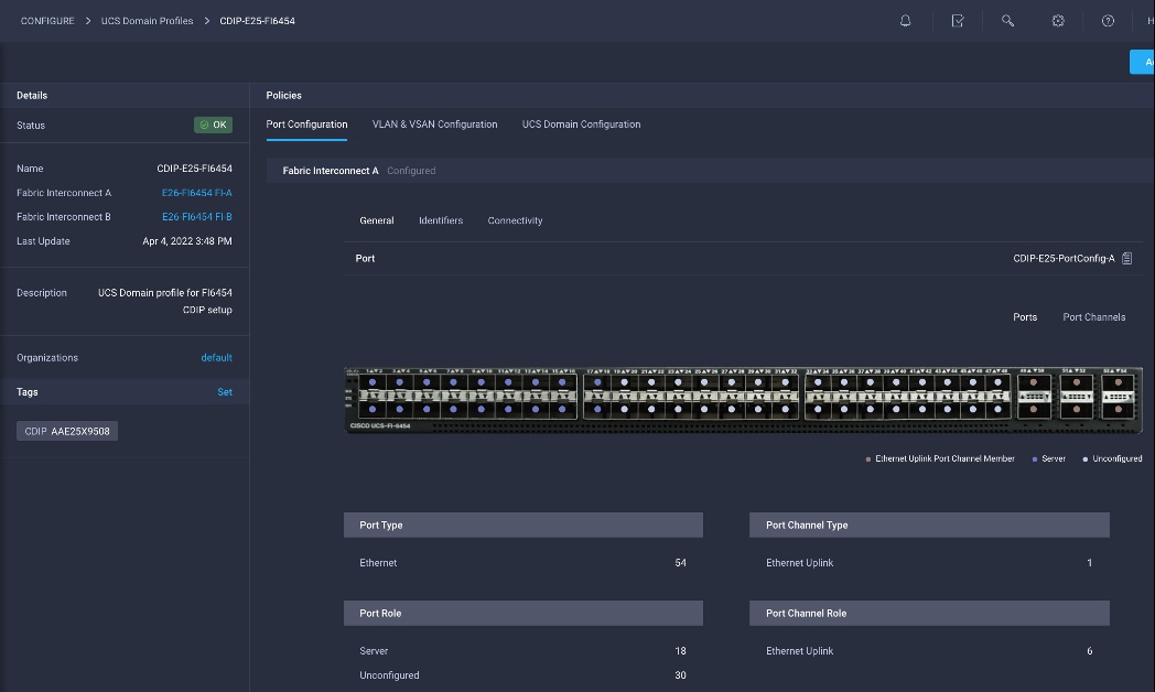
Cisco UCS Chassis Profile
The Cisco UCS X9508 Chassis and Cisco UCS X210c M6 Compute Nodes are automatically discovered when the ports are successfully configured using the domain profile, as shown in the following figures.
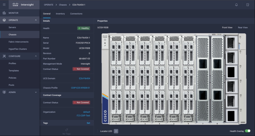
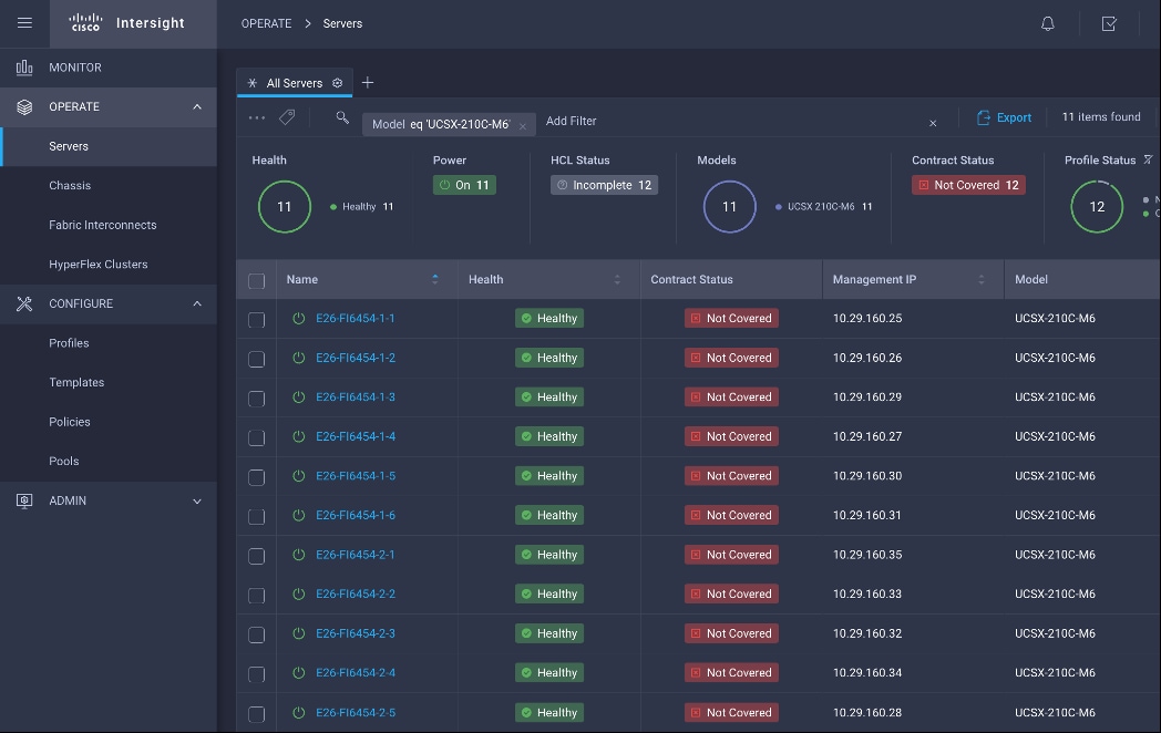
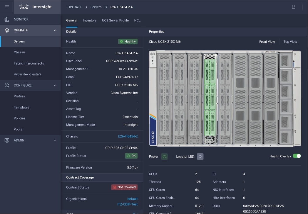
Create UCS Chassis Profile(s) to assign and deploy newly discovered 9508 chassis.
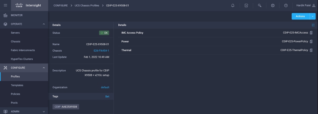
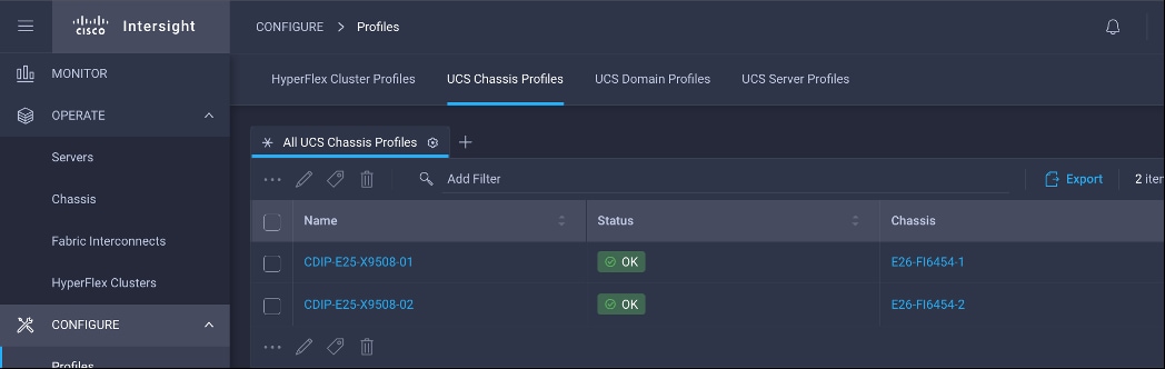
Server Profile Template
A server profile template enables resource management by simplifying policy alignment and server configuration. A server profile template is created using the server profile template wizard. The server profile template wizard groups the server policies into the following four categories to provide a quick summary view of the policies that are attached to a profile:
● Compute policies: BIOS, boot order, power, UUID, and virtual media policies
● Network policies: adapter configuration, LAN connectivity, and SAN connectivity policies
◦ The LAN connectivity policy requires you to create Ethernet network policy, Ethernet adapter policy, and Ethernet QoS policy.
● Storage policies: RAID1 for boot disk
● Management policies: device connector, Intelligent Platform Management Interface (IPMI) over LAN, Lightweight Directory Access Protocol (LDAP), local user, network connectivity, Simple Mail Transfer Protocol (SMTP), Simple Network Management Protocol (SNMP), Secure Shell (SSH), Serial over LAN (SOL), syslog, and virtual Keyboard, Video, and Mouse (KVM) policies.
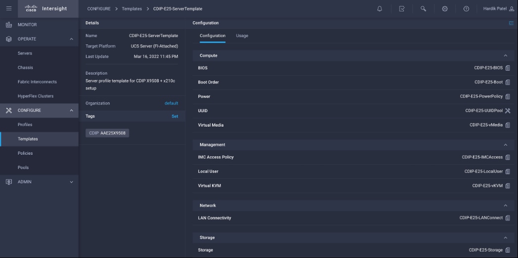
Obtain and Deploy Server Profiles from the Cisco Intersight Server Profile Template
The Cisco Intersight server profile allows server configurations to be deployed directly on the compute nodes based on polices defined in the server profile template. After a server profile template has been successfully created, server profiles can be derived from the template and associated with the Cisco UCS X210c M6 Compute Nodes as shown in Figure 44.
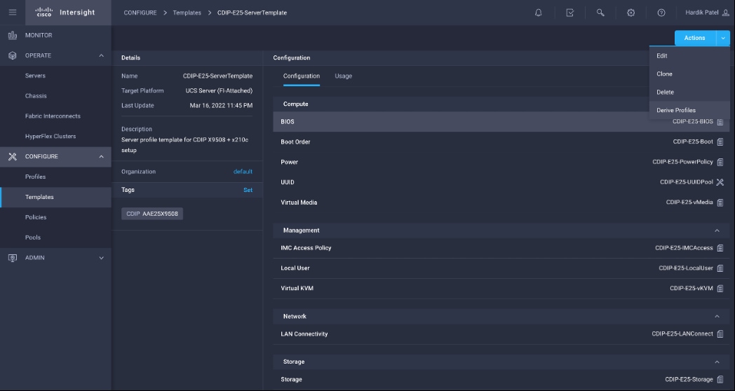
Procedure 3. Cisco Intersight Storage Policy Creation
Step 1. Go to Configure > Policies > Create Policy.
Step 2. Select policy type as Storage.
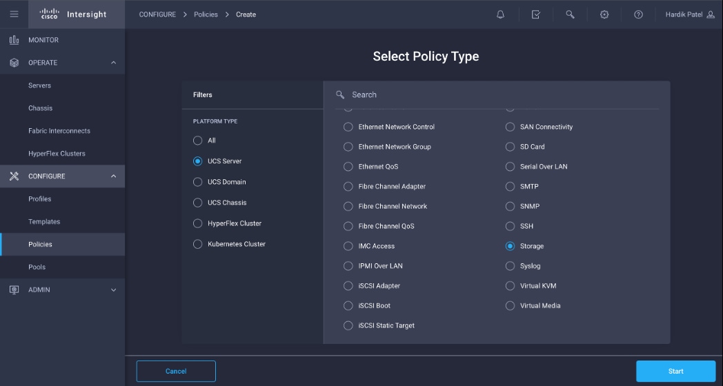
Step 3. Provide a general name, description, and tag for the policy to be created.
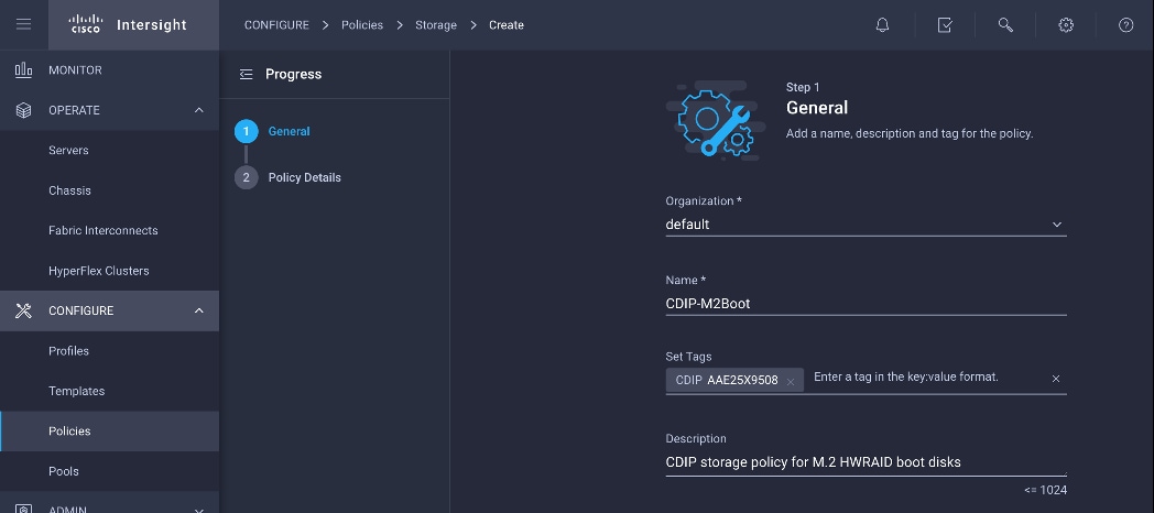
Step 4. Enable JBOD drives for virtual drive creation, select state of the unused drive.
Step 5. Enable M.2 configuration and select MSTOR-RAID1.
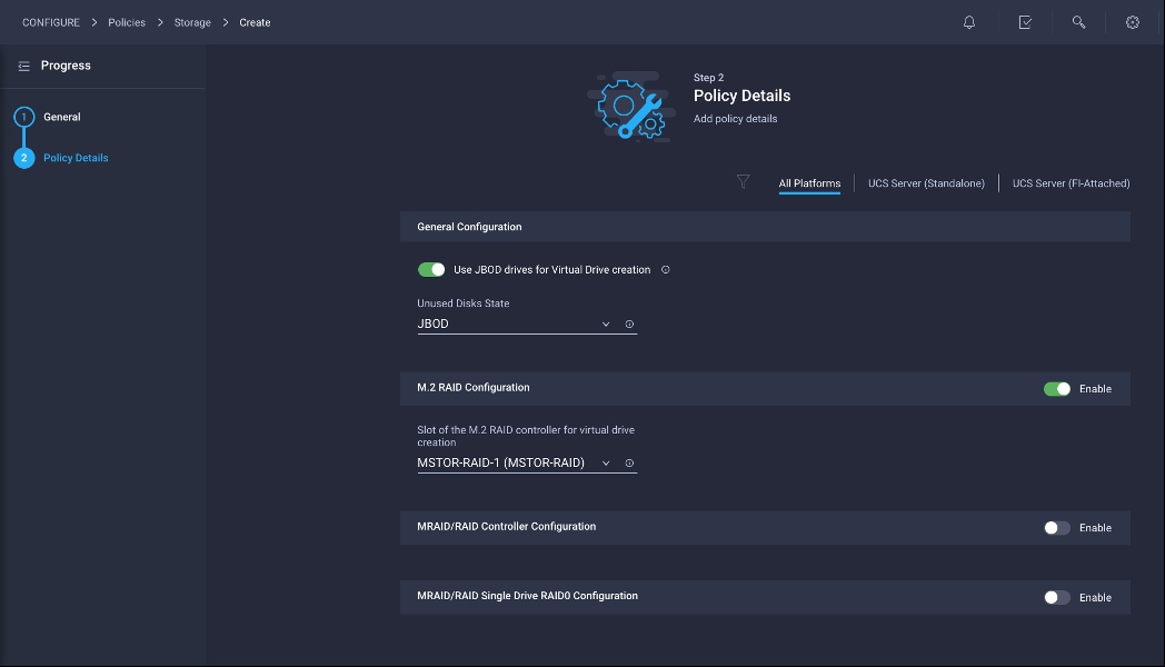
When an assigned profile is associated to a server with an M.2 HWRAID controller, it displays the virtual drive property as Server:
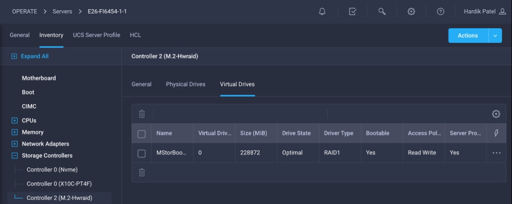
Procedure 4. Cisco Intersight Boot Policy Creation with Secure Boot
Step 1. Create/Edit BIOS policy; Trusted Platform > Intel Trusted Execution Technology Support – Enabled.
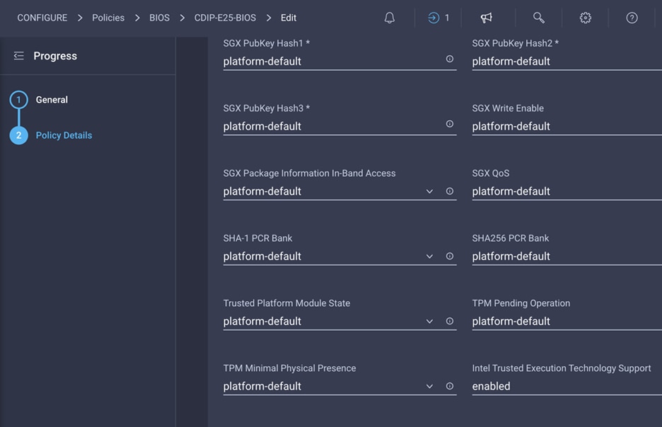
Step 2. Go to Configure > Policies > Create Policy.
Step 3. Select policy type as Boot Order.
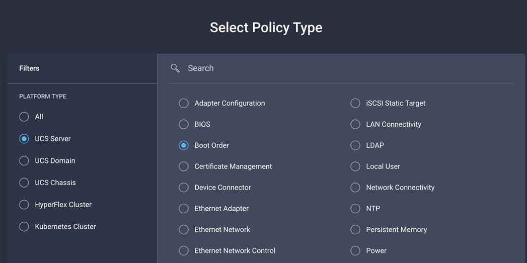
Step 4. Enter details for new policy.
Step 5. Configure Boot Mode as UEFI and Select Enable Secure Boot.
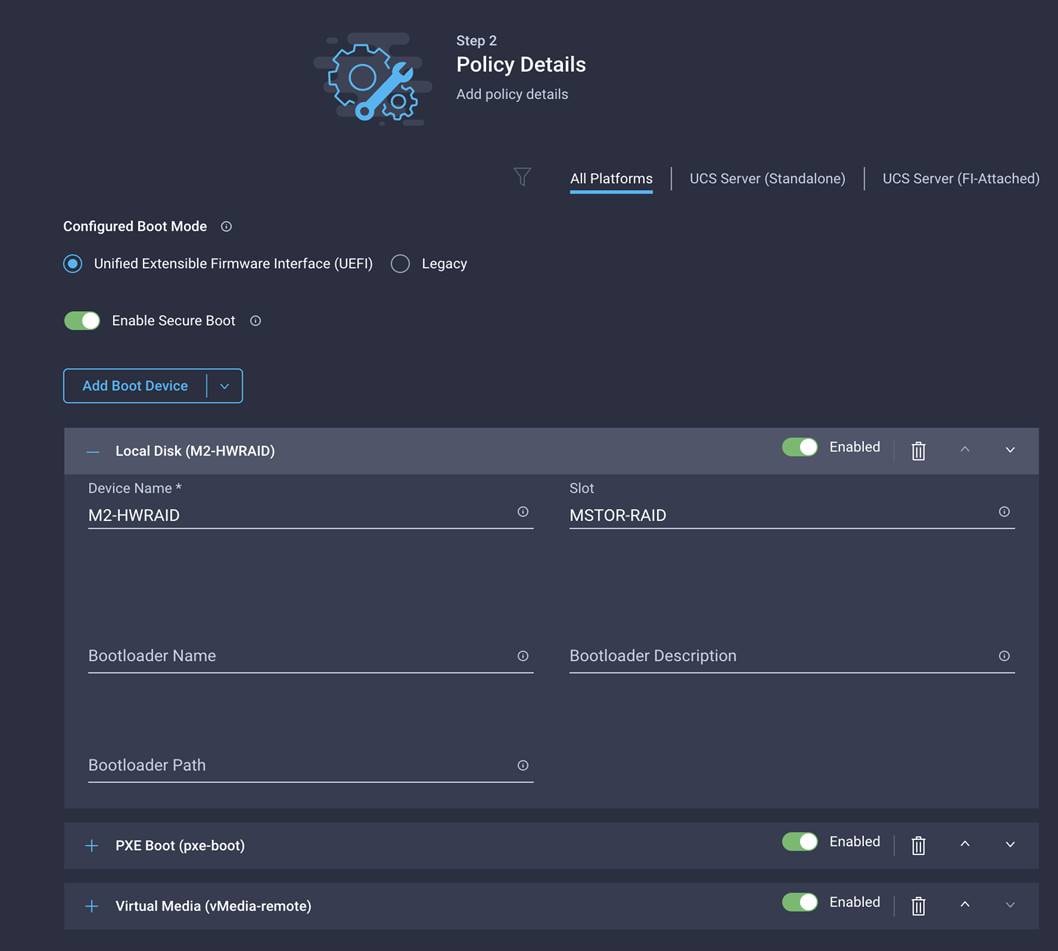
Deploy Red Hat OpenShift Container Platform (RHOCP)
This chapter contains the following:
● Edit and Configure TFTP Server
● Copy ISO File Contents to FTP Server Folder
● Bastion Node – Installation and Configuration
● Deploy Red Hat OpenShift Container Storage
Before continuing the RHOCP deployment, review the prerequisites outlined for RHOCP deployment on bare metal: https://docs.openshift.com/container-platform/4.8/installing/installing_bare_metal/installing-bare-metal.html
Figure 45 shows the logical view of the RHOCP deployment.
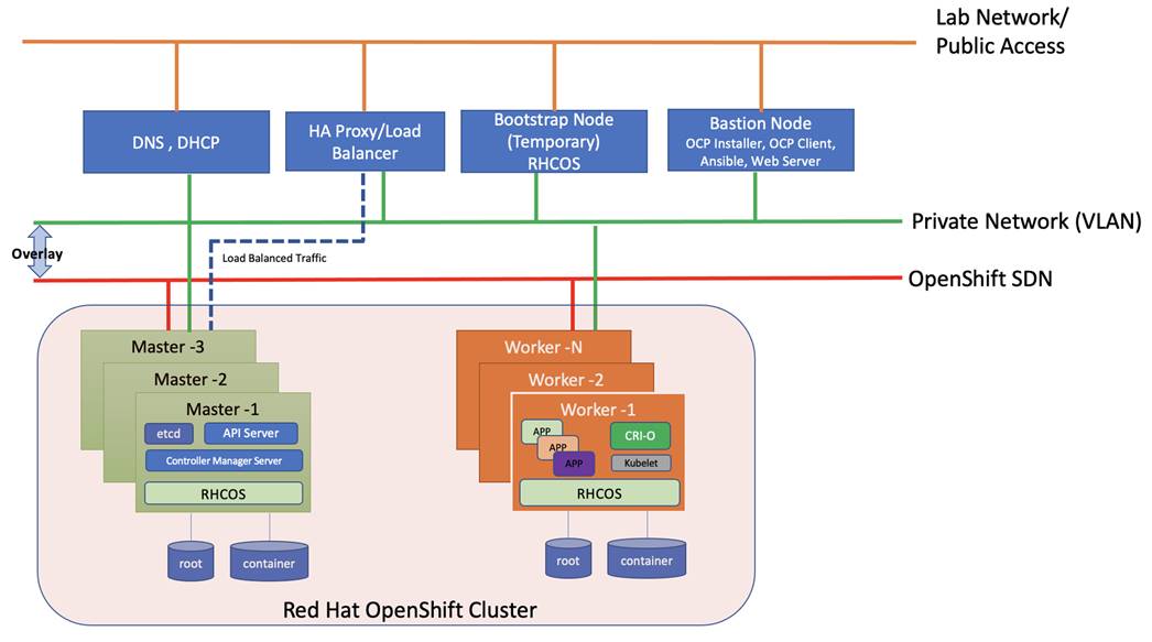
| Software |
Version |
| Red Hat OpenShift |
4.8 |
| Red Hat CoreOS |
4.8.14 |
| OpenShift Installation Program on Linux |
4.8.14 |
| OpenShift CLI on Linux |
4.8.14 |
The following are the prerequisites for Red Hat OpenShift Container Platform:
● Configure DHCP or set static IP addresses on each node.
● Provision the required load balancers.
● DNS is absolute MUST. Without proper DNS configuration, installation will not continue.
● Ensure network connectivity among nodes, DNS, DHCP (if used), HAProxy, Installer or Bastion node.
Note: It’s recommended to use the DHCP server to manage the machines for the cluster long-term. Ensure that the DHCP server is configured to provide persistent IP addresses and host names to the cluster machines.
Note: In the deployment, DHCP server is setup for installing CoreOS for bootstrap, master, and worker nodes.
Minimum Required Machines
The smallest OpenShift Container Platform clusters require the following hosts:
● 1 x temporary bootstrap machine
● 3 x Control plane, or master machines
● 2+ compute machines, which are also known as worker machines
Note: Bootstrap node is only used during the install time. its main purpose is to run bootkube. bootkube technically provides a temporary single node master k8 for bootstraping. After installation, this node can be removed or repurposed.
Note: For control plane high availability, it is recommended to use separate physical machine.
High-level Red Hat OpenShift Installation Checklist
There are two approaches for OCP deployment:
● Installer Provisioned Infrastructure (IPI)
● User Provisioned Infrastructure (UPI)
For detailed information about the installation types, please refer to Red Hat documentation. This OCP deployment is based on UPI.
A UPI-based installation involves the following high-level steps:
1. Configure DNS.
2. Setup and configure DHCP server.
3. Configure Load Balancer.
4. Setup non-cluster host to run a web server reachable by all nodes.
5. Setup OCP installer program.
6. Setup DHCP (Optional if using static IP).
7. Create install-config.yaml as per your environment.
8. Use the openshift-install command to generate the RHEL CoreOS ignition manifests, host these files via the web server.
9. PXE or ISO boot the cluster members to start the RHEL CoreOS and OpenShift install.
10. Monitor install progress with the openshift-install command.
11. Validate install using OpenShift client tool or launch the web console.
DNS Setup for RHOCP
DNS is used for name resolution and reverse name resolution. DNS A/AAAA or CNAME records are used for name resolution and PTR records are used for reverse name resolution. The reverse records are important because Red Hat Enterprise Linux CoreOS (RHCOS) uses the reverse records to set the host name for all the nodes. Additionally, the reverse records are used to generate the certificate signing requests (CSR) that OpenShift Container Platform needs to operate.
The following DNS records are required for an OpenShift Container Platform cluster that uses user-provisioned infrastructure. A complete DNS record takes the form: <component>.<cluster_name>.<base_domain>.
| Component |
DNS A/AAA Record |
IP Address |
Description |
| Kubernetes API |
api.sjc02-cdip.cisco.local |
10.10.1.10 |
IP address for the Load balancer for the control plane machines. These records must be resolvable by both clients external to the cluster and from all the nodes within the cluster. The API server must be able to resolve the worker nodes by the host names that are recorded in Kubernetes. If the API server cannot resolve the node names, then proxied API calls can fail, and you cannot retrieve logs from pods. |
| api-int.sjc02-cdip.cisco.local |
10.10.1.10 |
||
| Bootstrap |
bootstrap.sjc02-cdip.cisco.local |
10.10.1.80 |
bootstrap machine. |
| Master hosts |
master0.sjc02-cdip.cisco.local |
10.10.1.50 |
Master nodes |
| master1.sjc02-cdip.cisco.local |
10.10.1.51 |
||
| master2.sjc02-cdip.cisco.local |
10.10.1.52 |
||
| Worker hosts |
woker0.sjc02-cdip.cisco.local |
10.10.1.53 |
Worker nodes |
| woker1.sjc02-cdip.cisco.local |
10.10.1.54 |
||
| …… |
………. |
||
| wokerN.sjc02-cdip.cisco.local |
|
||
| Routes |
*.apps.sjc02-cdip.cisco.local |
10.10.1.10 |
For each control plane machine, OpenShift Container Platform also requires an SRV DNS record for etcd server on that machine with priority 0, weight 10 and port 2380. A cluster that uses three control plane machines re-quires the following records: |
|
|
|
|
Load balancer that targets the machines that run the Ingress router pods, which are the worker nodes by default. |
A wildcard for DNS zone must be configured for successful install and must ultimately resolve to IP address of load balancer such as HAProxy in this case. For example, *.apps.sjc02-cdip.cisco.local is configured in DNS to resolve to 10.10.1.10 (IP address of load balancer) as shown below:
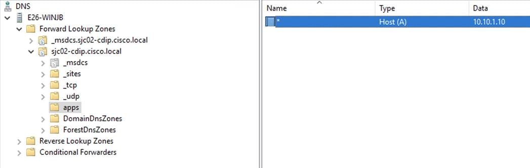
Procedure 1. Set Up Load Balancer
Note: Load balancer is required for Kubernetes API server, both internal and external as well as for OpenShift router.
Note: In this deployment, for simplicity, we used HAproxy to be installed and configured in Linux server. However, existing load balancer can also be configured as long as it can reach to all OpenShift nodes. This document does not make any official recommendation for any specific load balancer. We installed HAproxy single instance in Red Hat Enterprise Linux server 7.9 by running the following command.
Note: It is important to know that this HAproxy server installation is for reference purpose only, not for production setup.
Step 1. Install haproxy by running the following command
[root@bastion ~]# yum install -y haproxy
Step 2. After the install, configure /etc/haproxy/haproxy.cfg file. You need to configure port 6443 and 22623 to point to bootstrap and master nodes. You also need to configure port 80 and 443 to point to the worker nodes. Below is the example of HAproxy config used in this reference design.
Note: Make sure port 80 or 443 is not occupied in the server where HAProxy is being setup and firewall is configured to allow port numbers mentioned above.
Step 3. Edit haproxy.cfg file:
# cat /etc/haproxy/haproxy.cfg
#---------------------------------------------------------------------
# Example configuration for a possible web application. See the
# full configuration options online.
#
# http://haproxy.1wt.eu/download/1.4/doc/configuration.txt
#
#---------------------------------------------------------------------
#---------------------------------------------------------------------
# Global settings
#---------------------------------------------------------------------
global
# to have these messages end up in /var/log/haproxy.log you will
# need to:
#
# 1) configure syslog to accept network log events. This is done
# by adding the '-r' option to the SYSLOGD_OPTIONS in
# /etc/sysconfig/syslog
#
# 2) configure local2 events to go to the /var/log/haproxy.log
# file. A line like the following can be added to
# /etc/sysconfig/syslog
#
# local2.* /var/log/haproxy.log
#
log 127.0.0.1 local2
chroot /var/lib/haproxy
pidfile /var/run/haproxy.pid
maxconn 4000
user haproxy
group haproxy
daemon
# turn on stats unix socket
stats socket /var/lib/haproxy/stats
#---------------------------------------------------------------------
# common defaults that all the 'listen' and 'backend' sections will
# use if not designated in their block
#---------------------------------------------------------------------
defaults
mode http
log global
option httplog
option dontlognull
option http-server-close
#option forwardfor except 127.0.0.0/8
option redispatch
retries 3
timeout http-request 10s
timeout queue 1m
timeout connect 10s
timeout client 1m
timeout server 1m
timeout http-keep-alive 10s
timeout check 10s
maxconn 3000
frontend openshift-api-server
bind *:6443
default_backend openshift-api-server
mode tcp
option tcplog
backend openshift-api-server
balance source
mode tcp
#comment out or delete bootstrap entry after the successful install and restart haproxy
#server bootstrap.sjc02-cdip.cisco.local 10.10.1.80:6443 check
server master0.sjc02-cdip.cisco.local 10.10.1.50:6443 check
server master1.sjc02-cdip.cisco.local 10.10.1.51:6443 check
server master2.sjc02-cdip.cisco.local 10.10.1.52:6443 check
frontend machine-config-server
bind *:22623
default_backend machine-config-server
mode tcp
option tcplog
backend machine-config-server
balance source
mode tcp
# comment out or delete bootstrap entry after the successful install and restart haproxy
server bootstrap.sjc02-cdip.cisco.local 10.10.1.80:22623 check
server master0.sjc02-cdip.cisco.local 10.10.1.50:22623 check
server master1.sjc02-cdip.cisco.local 10.10.1.51:22623 check
server master2.sjc02-cdip.cisco.local 10.10.1.52:22623 check
frontend ingress-http
bind *:80
default_backend ingress-http
mode tcp
option tcplog
backend ingress-http
balance source
mode tcp
server worker0.sjc02-cdip.cisco.local 10.10.1.53:80 check
server worker1.sjc02-cdip.cisco.local 10.10.1.54:80 check
server worker2.sjc02-cdip.cisco.local 10.10.1.55:80 check
server worker3.sjc02-cdip.cisco.local 10.10.1.56:80 check
server worker4.sjc02-cdip.cisco.local 10.10.1.57:80 check
server worker5.sjc02-cdip.cisco.local 10.10.1.53:80 check
server worker6.sjc02-cdip.cisco.local 10.10.1.54:80 check
server worker7.sjc02-cdip.cisco.local 10.10.1.55:80 check
server worker8.sjc02-cdip.cisco.local 10.10.1.56:80 check
# Specify master nodes if they are also acting as worker node
# Master node entries are not required if masters are not acting as worker node as well.
frontend ingress-https
bind *:443
default_backend ingress-https
mode tcp
option tcplog
backend ingress-https
balance source
mode tcp
server worker0.sjc02-cdip.cisco.local 10.10.1.53:443 check
server worker1.sjc02-cdip.cisco.local 10.10.1.54:443 check
server worker2.sjc02-cdip.cisco.local 10.10.1.55:443 check
server worker3.sjc02-cdip.cisco.local 10.10.1.56:443 check
server worker4.sjc02-cdip.cisco.local 10.10.1.57:443 check
server worker5.sjc02-cdip.cisco.local 10.10.1.53:80 check
server worker6.sjc02-cdip.cisco.local 10.10.1.54:80 check
server worker7.sjc02-cdip.cisco.local 10.10.1.55:80 check
server worker8.sjc02-cdip.cisco.local 10.10.1.56:80 check
# Specify master nodes if they are also acting as worker node
# Master node entries are not required if masters are not acting as worker node as well.
Step 4. Restart the HAProxy service and verify that it is running without any issues:
# systemctl restart haproxy
# systemctl status haproxy -l
Note: Please refer to the haproxy documentation for more detailed installation and configuration steps: https://access.redhat.com/documentation/en-us/red_hat_enterprise_linux/7/html/load_balancer_administration/install_haproxy_example1
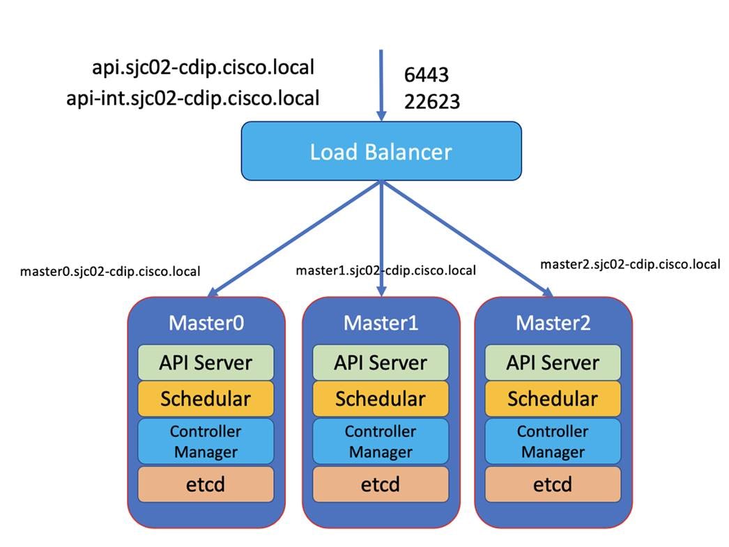
A webserver is also required to be set up for placing the ignition configurations and installation images for Red Hat CoreOS. The webserver must be reached by bootstrap, master, and worker nodes during the installation.
Note: In this design, we setup the Apache web server (httpd).
Note: If you are setting up webserver and HAProxy in bastion node for serving installation files, iso, and CoreOS image, make sure it is not using default port 80 as it would conflict with HAproxy configuration.
Step 1. If the webserver is not already installed. Run the following command in installer server:
# yum install -y httpd
Step 2. Edit ‘httpd.conf’ file with port number accessible.
Note: We configured port 8080 as shown below. Add port 8080 in the list of allowed ports in the firewall if firewall service is running.
# cat /etc/httpd/conf/httpd.conf | grep 8080
Listen 8080
ServerName 10.29.160.15:8080
Step 3. Edit ‘/etc/httpd/conf.d/ssl.conf file as following
# vi /etc/httpd/conf.d/ssl.conf
SSLCertificateFile /etc/pki/tls/certs/httpd.crt
SSLCertificateKeyFile /etc/pki/tls/private/httpd.key
Step 4. Start httpd service.
# systemctl start httpd.service
# systemctl enable httpd.service
Step 5. Create a folder for ignition files and CoreOS image:
# mkdir -p /var/www/html/ignition-install
Step 6. Download Red Hat CoreOS image to this folder:
cd /var/www/html/ignition-install
# curl -J -L -O https://mirror.openshift.com/pub/openshift-v4/x86_64/dependencies/rhcos/4.8/latest/rhcos-4.8.14-x86_64-metal.x86_64.raw.gz
# curl -J -L -O https://mirror.openshift.com/pub/openshift-v4/x86_64/dependencies/rhcos/4.8/latest/rhcos-4.8.14-x86_64-live.x86_64.iso
# curl -J -L -O https://mirror.openshift.com/pub/openshift-v4/x86_64/dependencies/rhcos/4.8/latest/rhcos-4.8.14-x86_64-live-rootfs.x86_64.img
# curl -J -L -O https://mirror.openshift.com/pub/openshift-v4/x86_64/dependencies/rhcos/4.8/latest/rhcos-4.8.14-x86_64-live-initramfs.x86_64.img
# curl -J -L -O https://mirror.openshift.com/pub/openshift-v4/x86_64/dependencies/rhcos/4.8/latest/rhcos-4.8.14-x86_64-live-kernel-x86_64
Note: For the PXE setup, the following configuration is required in Cisco Intersight for PXE booting Cisco UCS X-series servers.
Step 1. In Cisco Intersight, Configure > Policies > Select Create Policy > Boot Order. Create boot policy for PXE boot as shown below. Specify the interface that will be used to receive the IP address via DHCP. Eth0 is used in this case.
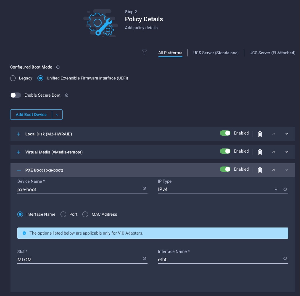
Note: DHCP is recommended for large scale production deployment to provide persistent IP addresses and host names to all the cluster nodes. Use IP reservation, so that IP should not change during node reboots.
Note: In this deployment, PXE server is setup in RHEL 8.4 for installing CoreOS in bootstrap, master, and worker nodes. In this configuration, we have specified IP reservation of RHOCP nodes with MAC address of the interface configured for PXE boot. MAC address of the interface can be obtained from Cisco Intersight.
Note: In this reference design, the DHCP setup is for reference purpose only. It is not recommended for production grade setup. In many cases, already existing DHCP setup can be utilized.
Step 1. To install the required packages, run the following:
# yum install dhcp tftp tftp-server syslinux vsftpd xinetd
Assumptions
The following are assumed:
● PXE setup requirements such as DHCP, TTFP, HTTP is hosted in a single server, although it is not mandatory.
● The PXE server can reach the internet.
● The PXE server is setup on Red Hat Enterprise Linux (RHEL) 8.4
Note: For configuring DHCP, specify the subnet and range used for offering the IP address via DHCP. You can also specify lease time.
Note: In this configuration, we specified the IP reservation for OCP nodes with the MAC address of the interface configured for PXE boot.
Step 1. Configure DHCP using the following conf file. This configuration file is for reference purpose only, change according to your environment. Adding more worker nodes for scaling requires an entry in DNS and IP reservation with MAC address in below dhcp.conf file:
# cat /etc/dhcp/dhcpd.conf
#
# DHCP Server Configuration file.
# see /usr/share/doc/dhcp*/dhcpd.conf.example
# see dhcpd.conf(5) man page
#
ddns-update-style interim;
ignore client-updates;
authoritative;
allow booting;
allow bootp;
allow unknown-clients;
# internal subnet for my DHCP Server
subnet 10.10.1.0 netmask 255.255.255.0 {
range 10.10.1.50 10.10.1.100;
option domain-name-servers 10.10.1.4;
option domain-name "sjc02-cdip.cisco.local";
option broadcast-address 10.10.1.255;
option routers 10.10.1.4;
default-lease-time 600;
max-lease-time 7200;
next-server 10.10.1.10;
filename "grubx64.efi";
host bootstrap {
hardware ethernet 6C:B2:AE:3A:35:6A;
fixed-address 10.10.1.80;
}
host master0 {
hardware ethernet 00:25:B5:00:26:00;
fixed-address 10.10.1.50;
}
host master1 {
hardware ethernet 00:25:B5:00:26:01;
fixed-address 10.10.1.51;
}
host master2 {
hardware ethernet 00:25:B5:00:26:02;
fixed-address 10.10.1.52;
}
host worker0 {
hardware ethernet 00:25:B5:00:26:06;
fixed-address 10.10.1.53;
}
host worker1 {
hardware ethernet 00:25:B5:00:26:07;
fixed-address 10.10.1.54;
}
host worker2 {
hardware ethernet 00:25:B5:00:26:08;
fixed-address 10.10.1.55;
}
host worker3 {
hardware ethernet 00:25:B5:00:26:09;
fixed-address 10.10.1.56;
}
host worker4 {
hardware ethernet 00:25:B5:00:26:0A;
fixed-address 10.10.1.57;
}
host worker5 {
hardware ethernet 00:25:B5:00:26:0B;
fixed-address 10.10.1.58;
}
host worker6 {
hardware ethernet 00:25:B5:00:26:0C;
fixed-address 10.10.1.59;
}
host worker7 {
hardware ethernet 00:25:B5:00:26:0D;
fixed-address 10.10.1.60;
}
host worker8 {
hardware ethernet 00:25:B5:00:26:0E;
fixed-address 10.10.1.61;
}
}
Step 2. Each time the dhcpd.conf is modified, restart the dhcpd service as shown below:
# systemctl restart dhcpd
# systemctl status dhcpd
# systemctl enable dhcpd
Procedure 6. Edit and Configure TFTP Server
Note: TFTP (Trivial File Transfer Protocol) is used to transfer files from server to clients without any kind of authentication. In the case of PXE, TFTP perform bootstrap loading.
The TFTP server is needed to provide the following:
● initrd.img – The boot loader which will be loaded to RAM disk.
● vmlinuz – A compressed bootable Linux Kernel.
Step 1. To configure tftp, edit the following configuration file:
# cat /etc/xinetd.d/tftp
# default: off
# description: The tftp server serves files using the trivial file transfer \
# protocol. The tftp protocol is often used to boot diskless \
# workstations, download configuration files to network-aware printers, \
# and to start the installation process for some operating systems.
service tftp
{
socket_type = dgram
protocol = udp
wait = yes
user = root
server = /usr/sbin/in.tftpd
server_args = -s /var/lib/tftpboot
disable = no
per_source = 11
cps = 100 2
flags = IPv4
}
Step 2. All the network boot related files are to be placed in tftp root directory “/var/lib/tftpboot”
Step 3. Run the following commands to copy required network boot files in ‘/var/lib/tftpboot/’
# cp -v /usr/share/syslinux/pxelinux.0 /var/lib/tftpboot
# cp -v /usr/share/syslinux/menu.c32 /var/lib/tftpboot
# cp -v /usr/share/syslinux/memdisk /var/lib/tftpboot
# cp -v /usr/share/syslinux/mboot.c32 /var/lib/tftpboot
# cp -v /usr/share/syslinux/chain.c32 /var/lib/tftpboot
#
# mkdir /var/lib/tftpboot/pxelinux.cfg
# mkdir /var/lib/tftpboot/networkboot
Step 4. Create subfolder in /var/lib/tftpboot/networkboot for each OS being configured for PXE boot. For example, in this case, RHEL 8.4 and CoreOS 4.8.14
# mkdir /var/lib/tftpboot/networkboot/rhel84
# mkdir /var/lib/tftpboot/networkboot/coreos4814
Step 5. Download the iso file CoreOS 4.8.14 and move it to PXE server.
Note: For example, run the following to download the CoreOS 4.8.14 iso.
Note: # curl -J -L -O https://mirror.openshift.com/pub/openshift-v4/x86_64/dependencies/rhcos/4.8/latest/rhcos-4.8.14-x86_64-live.x86_64.iso
Step 6. Create a sub folder in ‘/var/ftp/pub’ for each OS to store the boot image files.
# mkdir /var/ftp/pub/coreos4814
Step 7. Run the following commands to mount iso file both for CoreOS 4.8.14 and then copy its contents in ftp server’s directory ‘/var/ftp/pub/coreos4814
Perform the following for each OS iso file. In this setup we created PXE boot for RHEL 8.4 and CoreOS 4.8.29
# mount -o loop rhcos-4.8.14-x86_64-live.x86_64.iso /mnt
mount: /dev/loop0 is write-protected, mounting read-only
# cd /mnt/
# cp -av * /var/ftp/pub/coreos4814
Content of coreos4814 is shown below:
# ls -l /var/ftp/pub/coreos4814/
total 4
dr-xr-xr-x 3 root root 20 Mar 22 2022 EFI
dr-xr-xr-x 3 root root 60 Mar 22 2022 images
dr-xr-xr-x 2 root root 156 Mar 22 2022 isolinux
-r--r--r-- 1 root root 132 Mar 22 2022 zipl.prm
Procedure 7. Copy ISO File Contents to FTP Server Folder
Step 1. Copy Kernel file (vmlimz) and initrd file from mounted iso file.
Step 2. For CoreOS copy to ‘/var/lib/tftpboot/networkboot/coreos4814’
# cp /var/ftp/pub/coreos4814/images/pxeboot/* /var/lib/tftpboot/networkboot/coreos4814/
# ls -ll /var/lib/tftpboot/networkboot/coreos4814/
total 891548
-r--r--r-- 1 root root 82475312 Mar 22 18:03 initrd.img
-r--r--r-- 1 root root 821538304 Mar 22 18:03 rootfs.img
-r--r--r-- 1 root root 8928624 Mar 22 18:03 vmlinuz
Note: In case of CoreOS, you can also download kernel, initramfs, and rootfs from Red Hat Mirror site (https://mirror.openshift.com/pub/openshift-v4/x86_64/dependencies/rhcos/4.8/latest) and store it in the /var/lib/tfpboot/networkboot/coreos4814 folder instead of getting it from iso file.
Step 3. Unmount the iso file using ‘umount’ command.
# umount /mnt/
Step 4. Verify the content of the FTP server in the browser as shown below. Make sure your FTP service is running.
ftp://10.10.1.10/pub/coreos4814
Step 5. Configure grub.cfg for UEFI or pxelinux.cfg/default for creating PXE menu.
# cat /var/lib/tftpboot/grub.cfg
set timeout=60
# for bootstrap node
menuentry 'Install RHEL CoreOS 4.8.14 Bootstrap Node' --class fedora --class gnu-linux --class gnu --class os {
linuxefi /networkboot/coreos4814/vmlinuz inst.repo=ftp://10.10.1.10/pub/coreos4814 coreos.live.rootfs_url=http://10.10.1.10:8080/ignition-install/rhcos-4.8.14-x86_64-live-rootfs.x86_64.img nomodeset rd.neednet=1 coreos.inst=yes coreos.inst.install_dev=sda coreos.inst.image_url=http://10.10.1.10:8080/ignition-install/rhcos-4.8.14.47-x86_64-metal.x86_64.raw.gz coreos.inst.insecure coreos.inst.ignition_url=http://10.10.1.10:8080/ignition-install/bootstrap.ign
initrdefi /networkboot/coreos4814/initrd.img
}
# for master node
menuentry 'Install RHEL CoreOS 4.8.14 Master Node' --class fedora --class gnu-linux --class gnu --class os {
linuxefi /networkboot/coreos4814/vmlinuz inst.repo=ftp://10.10.1.10/pub/coreos4814 coreos.live.rootfs_url=http://10.10.1.10:8080/ignition-install/rhcos-4.8.14-x86_64-live-rootfs.x86_64.img nomodeset rd.neednet=1 coreos.inst=yes coreos.inst.install_dev=sda coreos.inst.image_url=http://10.10.1.10:8080/ignition-install/rhcos-4.8.14.47-x86_64-metal.x86_64.raw.gz coreos.inst.insecure coreos.inst.ignition_url=http://10.10.1.10:8080/ignition-install/master.ign
initrdefi /networkboot/coreos4814/initrd.img
}
# for worker node
menuentry 'Install RHEL CoreOS 4.8.14 Worker Node' --class fedora --class gnu-linux --class gnu --class os {
linuxefi /networkboot/coreos4814/vmlinuz inst.repo=ftp://10.10.1.10/pub/coreos4814 coreos.live.rootfs_url=http://10.10.1.10:8080/ignition-install/rhcos-4.8.14-x86_64-live-rootfs.x86_64.img nomodeset rd.neednet=1 coreos.inst=yes coreos.inst.install_dev=sda coreos.inst.image_url=http://10.10.1.10:8080/ignition-install/rhcos-4.8.14.47-x86_64-metal.x86_64.raw.gz coreos.inst.insecure coreos.inst.ignition_url=http://10.10.1.10:8080/ignition-install/worker.ign
initrdefi /networkboot/coreos4814/initrd.img
}
Step 6. Start and enable xinetd, dhcp and vsftpd service.
Step 7. Use the following commands to start and enable xinetd, dhcp and vsftpd.
# systemctl start xinetd
# systemctl enable xinetd
# systemctl start dhcpd.service
# systemctl enable dhcpd.service
# systemctl start vsftpd
# systemctl enable vsftpd
# systemctl start tftp
# systemctl enable tftp
Step 8. If SELinux is enabled, set the following selinux rule for the FTP server.
# setsebool -P allow_ftpd_full_access 1
Bastion Node – Installation and Configuration
This subject contains the following procedures:
● Create an Installation Folder
● Generate an SSH Private Key and Add to Agent
● Obtain the Installation and CLI for Linux
● Manually Create the Installation Configuration File
● Create Kubernetes Manifest and Ignition Configuration Files
● Install Red Hat Core OS (RHCOS)
● Approve Certificate Signing Requests for Machines
The Red Hat OpenShift Container Platform bastion node should be installed with Red Hat Enterprise Linux 7.9 or newer. You can choose their preferred installation method which could be CIMC mounted vMedia DVD install method. This document does not explain Bastion node OS installation steps, as it is time-tested, standard procedure. Bastion node needs standard base RHEL server operating system packages.
Note: Bastion node configuration for OS, network and storage remains the same for both Production and Dev/ Test use case architectures.
Procedure 1. Create an Installation Folder
Step 1. Create an installation folder on bastion node:
[root@bastion ~]# mkdir -p ocp-install
Procedure 2. Generate an SSH Private Key and Add to Agent
Note: If you want to perform installation debugging or disaster recovery on your cluster, you must provide an SSH key to both your ssh-agent and the installation program.
Note: You can use this key to SSH into the master, bootstrap, and worker nodes as the user core. When you deploy the cluster, the key is added to the core user’s ~/.ssh/authorized_keys list.
Step 1. Run the following command:
# mkdir ocp-install
# cd ocp-install
# ssh-keygen -t ed25519 -N '' -f installer
Generating public/private ed25519 key pair.
Your identification has been saved in installer.
Your public key has been saved in installer.pub.
The key fingerprint is:
SHA256:FieOoh6oM55AHrTmg901bnKgakJnZ6QgG8JG0kxirgk root@bastion.sjc02-cdip.cisco.local
The key's randomart image is:
+--[ED25519 256]--+
|.=. |
|+oo |
|Eo o . |
|B=. . o + |
|*B. = + S |
|B+.B B o |
|=+B = + |
|*+o. + |
|*=. |
+----[SHA256]-----+
Step 2. Start the ssh-agent process as a background task:
# eval "$(ssh-agent -s)"
Step 3. Add your SSH private key to the ssh-agent:
# ssh-add installer
Procedure 3. Obtain the Installation and CLI for Linux
Note: Before you install Red Hat OpenShift Container Platform (RHOCP), download the OpenShift installation file and set it up in a bastion node.
Step 1. Access the Install OpenShift on Bare Metal with user-provisioned infrastructure page on the Red Hat OpenShift Cluster Manager site.
Step 2. Download the installation and client program for Linux operating system and place the file in the ocp-install directory where you will store the installation configuration files.
# curl -J -L -O https://mirror.openshift.com/pub/openshift-v4/x86_64/clients/ocp/stable-4.8/openshift-install-linux-4.8.29.tar.gz
# curl -J -L -O https://mirror.openshift.com/pub/openshift-v4/x86_64/clients/ocp/stable-4.8/openshift-client-linux-4.8.29.tar.gz
Note: The installation program creates several files on the computer that you use to install your cluster. You must keep both the installation program and the files that the installation program creates after you finish installing the cluster.
Note: Deleting the files created by the installation program does not remove your cluster, even if the cluster failed during installation. You must complete the OpenShift Container Platform uninstallation procedures outlined for your specific cloud provider to remove your cluster entirely.
Note: If you installed an earlier version of oc, you cannot use it to complete all of the commands in OpenShift Container Platform 4.5. Download and install the new version of oc.
Step 3. Extract the installation program. Run the following command:
# tar -zxvf openshift-install-linux-4.8.29.tar.gz
# tar -xvzf openshift-client-linux-4.8.29.tar.gz
# chmod 777 openshift-install
Step 4. Export path for OpenShift install directory:
# export PATH=$PATH:/root/ocp-install/
# echo $PATH
/usr/local/sbin:/usr/local/bin:/usr/sbin:/usr/bin:/root/bin:/root/ocp-install/:/root/ocp-install/
Step 5. After you install the CLI, it is available using the oc command:
[root@bastion ocp-install]# oc <command>
Procedure 4. Download Pull Secret
Note: The installation program requires pull secret. This pull secret allows you to authenticate with the services that are provided by the included authorities, including Quay.io, which serves the container images for OpenShift Container Platform components.
Note: Without pull secret, the installation will not continue. It will be specified in the install config file in a subsequent section of this document.
Step 1. To download pull secret, login to OpenShift Cluster Manager Site, click “Download pull secret” or “Copy pull secret” option to copy in a clipboard.
Step 2. Save pull secret as .txt file.
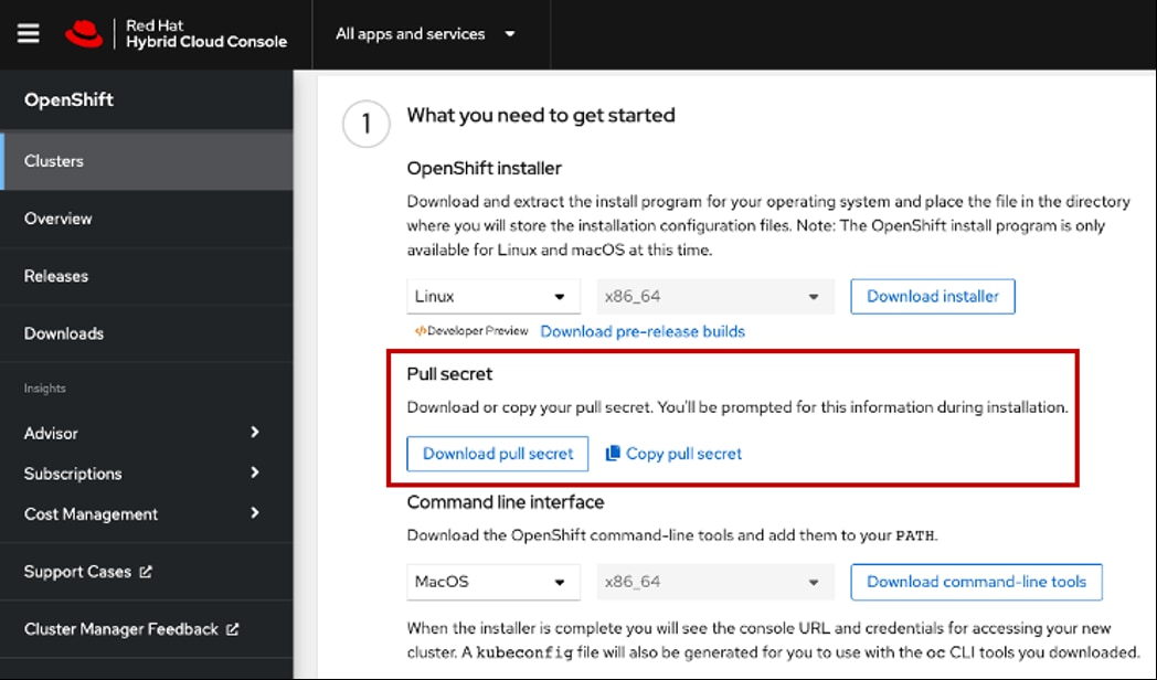
Procedure 5. Manually Create the Installation Configuration File
Note: For installations of OpenShift Container Platform that use user-provisioned infrastructure, you manually generate your installation configuration file.
Note: Some installation assets, like bootstrap X.509 certificates have short expiration intervals, so you must not reuse an installation directory. If you want to reuse individual files from another cluster installation, you can copy them into your directory. However, the file names for the installation assets might change between releases. Use caution when copying installation files from an earlier OpenShift Container Platform version.
Step 1. Customize the install-config.yaml file template and save it in the installation directory. Change the following according to your environment:
a. baseDomain – This is the domain in your environment. For example, we configure cisco.local as the base domain.
b. metadata.name – This would be clusterId (Note: This will effectively make all FQDNS sjc02-cdip.cisco.local)
c. sshKey – generated earlier in the Generate ssh private key section - # cat ~/.ssh/id_rsa.pub
# cat create-install-config.sh
cat <<EOF > install-config.yaml
apiVersion: v1
baseDomain: cisco.local
compute:
- hyperthreading: Enabled
name: worker
replicas: 0
controlPlane:
hyperthreading: Enabled
name: master
replicas: 3
metadata:
name: sjc02-cdip
networking:
clusterNetworks:
- cidr: 10.254.0.0/16
hostPrefix: 24
networkType: OpenShiftSDN
serviceNetwork:
- 172.30.0.0/16
platform:
none: {}
fips: false
pullSecret: '$(< /root/ocp-install/pull-secret.txt)'
sshKey: '$(< /root/ocp-install/installer.pub)'
EOF
[root@bastion ocp-install]# chmod 777 create_install_yaml.sh
[root@bastion ocp-install]# ./ create_install_yaml.sh
Note: You must name this configuration file install-config.yaml.
Step 2. Back up the install-config.yaml file so that you can use it to install multiple clusters:
[root@bastion ocp-install]# cp install-config.yaml install-config.yaml.bkp
Note: The install-config.yaml file is consumed during the next step of the installation process. You must back it up now.
Note: You can customize the install-config.yaml file to specify more details about your OpenShift Container Platform cluster’s platform or modify the values of the required parameters. For more details, https://docs.openshift.com/container-platform/4.8/installing/installing_bare_metal/installing-bare-metal.html
Procedure 6. Create Kubernetes Manifest and Ignition Configuration Files
| Tech tip |
| Ignition is a tool for manipulating configuration during early boot before the operating system starts. This includes things like writing files (regular files, systemd units, networkd units, and so on) and configuring users. Think of it as a cloud-init that runs once (during first boot). OpenShift installer generates these ignition configs to prepare the node as either bootstrap, master, or worker node. |
Step 1. From within your working directory (in this example it's /root/ocp-install) generate the ignition configs:
# ./openshift-install create ignition-configs --dir=/root/ocp-install
INFO Consuming Install Config from target directory
WARNING Making control-plane schedulable by setting MastersSchedulable to true for Scheduler cluster settings
INFO Ignition-Configs created in: /root/ocp-install and /root/ocp-install/auth
Note: Make sure install-config.yaml file should be in the working director such as /root/ocp-install directory in this case.
Note: Creating ignition config will result in the removal of install-config.yaml file. Make a backup of in-stall-config.yaml before creating ignition configs. You may have to recreate the new one if you need to re-create the ignition config files
The following files are generated in the directory:
.
├── auth
│ ├── kubeadmin-password
│ └── kubeconfig
├── bootstrap.ign
├── master.ign
├── metadata.json
└── worker.ign
As an example, the list of installation folders are shown below:
[root@ocp-pxe ocp-install]# ls -l
total 600536
drwxr-x---. 2 root root 50 Mar 22 17:00 auth
-rw-r-----. 1 root root 288791 Mar 22 17:00 bootstrap.ign
-rwxr-xr-x. 1 root root 508 Mar 22 15:58 create-install-config.sh
-rw-r--r--. 1 root root 3284 Mar 22 16:00 install-config.yaml.bkp
-rw-------. 1 root root 432 Mar 22 15:34 installer
-rw-r--r--. 1 root root 117 Mar 22 15:34 installer.pub
-rwxr-xr-x. 2 root root 74680680 Oct 12 09:02 kubectl
-rw-r-----. 1 root root 1724 Mar 22 17:00 master.ign
-rw-r-----. 1 root root 108 Mar 22 17:00 metadata.json
-rwxr-xr-x. 2 root root 74680680 Oct 12 09:02 oc
-rw-r--r--. 1 root root 24364046 Mar 22 15:36 openshift-client-linux-4.8.29.tar.gz
-rwxr-xr-x. 1 root root 353742848 Oct 12 08:48 openshift-install
-rw-r--r--. 1 root root 87138505 Mar 22 15:35 openshift-install-linux-4.8.29.tar.gz
-rw-r--r--. 1 root root 2771 Mar 22 15:44 pull-secret.txt
-rw-r--r--. 1 root root 954 Oct 12 09:02 README.md
-rwxr-xr-x. 1 root root 131 Mar 22 16:11 sshscript.sh
-rw-r-----. 1 root root 1724 Mar 22 17:00 worker.ign
Step 2. Copy the .ign file to your webserver:
# cp *.ign /var/www/html/ignition-install/
Step 3. Provide the appropriate permissions (otherwise, it will not work):
# chmod o+r /var/www/html/ignition-install/*.ign
Procedure 7. Install Red Hat Core OS (RHCOS)
Note: Before you begin installing RHCOS in bootstrap and master nodes, make sure you have the following files available in your webserver, as shown below:
Bootstrap.ign
Master.ign
Worker.ign
rhcos-4.8.29-x86_64-metal.x86_64.raw.gz
Note: # curl -J -L -O https://mirror.openshift.com/pub/openshift-v4/x86_64/dependencies/rhcos/4.8/latest/rhcos-4.8.29-x86_64-metal.x86_64.raw.gz
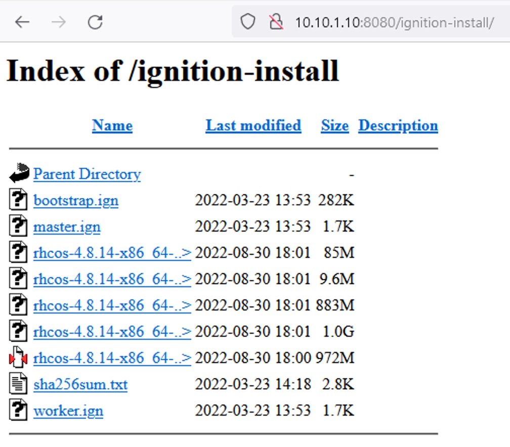
Step 1. Launch vKVM from Cisco Intersight and login to server vKVM console.
Step 2. Click Power > Power Cycle System
Step 3. Click Boot Device > Select LAN as shown below.
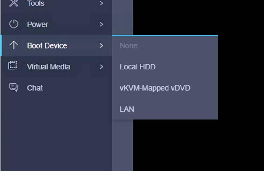
Step 4. Follow CoreOS installation for PXE boot menu as defined in grub.cfg. Select Bootstrap Node and hit enter key to begin bootstrap installation. Bootstrap node networking configuration will be performed as specified in dhcp.conf file and ignition configuration will be applied as specified in grub.cfg file.
12. Follow step 4 by selecting role based installation i.e. bootstrap, master and worker node installation for RedHat OpenShift Contain Platform deployment.
Step 5. Once the bootstrap node is up and running, repeat steps 1 - 4 for the master and worker nodes. Make sure you select appropriate role from boot menu.
Procedure 8. Monitor the Installation
Note: When the bootstrap server is up and running, the installation is already in progress. First the masters "check in" to the bootstrap server for its configuration. After the masters are done being configured, the bootstrap server "hands off" responsibility to the masters.
Step 1. Track the bootstrap process with the following command:
# ./openshift-install wait-for bootstrap-complete --log-level info
# ./openshift-install --dir=/root/ocp-install wait-for install-complete
INFO Waiting up to 40m0s for the cluster at https://api.sjc02-cdip.cisco.local:6443 to initialize...
INFO Waiting up to 10m0s for the openshift-console route to be created...
INFO Install complete!
INFO To access the cluster as the system:admin user when using 'oc', run 'export KUBECONFIG=/root/ocp-install/auth/kubeconfig'
INFO Access the OpenShift web-console here: https://console-openshift-console.apps.sjc02-cdip.cisco.local
INFO Login to the console with user: "kubeadmin", and password: "XXXXX-XXXXX-XXXXX-XXXXX"
INFO Time elapsed: 0s
# ./openshift-install wait-for bootstrap-complete --log-level debug
DEBUG OpenShift Installer 4.8.29
DEBUG Built from commit 1cfb1b32f5aaf0dfe0fb2ea9da41c710da9b2c76
INFO Waiting up to 20m0s for the Kubernetes API at https://api.sjc02-cdip.cisco.local:6443...
INFO API v1.21.11+6b3cbdd up
INFO Waiting up to 30m0s for bootstrapping to complete...
DEBUG Bootstrap status: complete
INFO It is now safe to remove the bootstrap resources
INFO Time elapsed: 0s
# watch -n5 oc get clusteroperators
Every 5.0s: oc get clusteroperators Fri Feb 4 17:03:14 2022
NAME VERSION AVAILABLE PROGRESSING DEGRADED SINCE
authentication 4.8.29 True False False 24m
cloud-credential 4.8.29 True False False 4h58m
cluster-autoscaler 4.8.29 True False False 4h48m
config-operator 4.8.29 True False False 4h49m
console 4.8.29 True False False 3h14m
csi-snapshot-controller 4.8.29 True False False 4h49m
dns 4.8.29 True False False 4h47m
etcd 4.8.29 True False False 3h24m
image-registry 4.8.29 True False False 3h20m
ingress 4.8.29 True False False 86m
insights 4.8.29 True False False 4h49m
kube-apiserver 4.8.29 True False False 3h22m
kube-controller-manager 4.8.29 True False False 4h47m
kube-scheduler 4.8.29 True False False 4h47m
kube-storage-version-migrator 4.8.29 True False False 87m
machine-api 4.8.29 True False False 4h49m
machine-approver 4.8.29 True False False 4h49m
machine-config 4.8.29 True False False 26m
marketplace 4.8.29 True False False 89m
monitoring 4.8.29 True False False 45m
network 4.8.29 True False False 4h49m
node-tuning 4.8.29 True False False 4h49m
openshift-apiserver 4.8.29 True False False 26m
openshift-controller-manager 4.8.29 True False False 4h48m
openshift-samples 4.8.29 True False False 3h18m
operator-lifecycle-manager 4.8.29 True False False 4h49m
operator-lifecycle-manager-catalog 4.8.29 True False False 4h48m
operator-lifecycle-manager-packageserver 4.8.29 True False False 87m
service-ca 4.8.29 True False False 4h49m
storage 4.8.29 True False False 4h49m
Step 2. Monitor the detailed installation progress by SSH to bootstrap node and run the following command:
# ssh core@bootstrap.sjc02-cdip.cisco.local
# journalctl -b -f -u release-image.service -u bootkube.service
Note: After bootstrap process is complete, remove the bootstrap machine from the load balancer.
Note: For more information about commonly known issue and troubleshoot installation issues, go to: https://docs.openshift.com/container-platform/4.8/installing/installing-troubleshooting.html
Procedure 9. Log into the Cluster
Note: Log in to the cluster as a default system user by exporting the cluster kubeconfig file. The kubeconfig file contains information about the cluster that is used by the CLI to connect a client to the correct cluster and API server. The file is specific to a cluster and is created during OpenShift Container Platform installation.
Step 1. Export the kubeadmin credentials:
# export KUBECONFIG=auth/kubeconfig
# oc whoami
system:admin
Step 2. Verify ability to run oc command:
# oc get nodes
NAME STATUS ROLES AGE VERSION
master0.sjc02-cdip.cisco.local Ready master 30m v1.21.11+6b3cbdd
master1.sjc02-cdip.cisco.local Ready master 31m v1.21.11+6b3cbdd
master2.sjc02-cdip.cisco.local Ready master 30m v1.21.11+6b3cbdd
worker0.sjc02-cdip.cisco.local Ready worker 44m v1.21.11+6b3cbdd
worker1.sjc02-cdip.cisco.local Ready worker 50m v1.21.11+6b3cbdd
worker2.sjc02-cdip.cisco.local Ready worker 52m v1.21.11+6b3cbdd
worker3.sjc02-cdip.cisco.local Ready worker 55m v1.21.11+6b3cbdd
worker4.sjc02-cdip.cisco.local NotReady worker 46s v1.21.11+6b3cbdd
Procedure 10. Approve Certificate Signing Requests for Machines
Note: When you add machine(s) to a cluster, two pending certificate signing requests (CSRs) are generated for each machine that you added. You must confirm that these CSRs are approved or, if necessary, approve them yourself. The client requests must be approved first, followed by the server requests.
Step 1. Confirm that the cluster recognizes the machines. The output lists all of the machines added in the cluster:
# oc get nodes
Step 2. Review the pending CSRs and ensure that you see the client requests with the Pending or Approved status for each machine that you added to the cluster:
# oc get csr | grep -i pending
csr-phsw7 2m15s kubernetes.io/kubelet-serving system:node:worker4.sjc02-cdip.cisco.local Pending
Step 3. If the CSRs were not approved, after all of the pending CSRs for the machines you added are in Pending status, approve the CSRs for your cluster machines:
Note: Since the CSRs rotate automatically, approve your CSRs within an hour of adding the machines to the cluster. If you do not approve them within an hour, the certificates will rotate, and more than two certificates will be present for each node. You must approve all of these certificates. After you approve the initial CSRs, the subsequent node client CSRs are automatically approved by the cluster kube-controller-manager. You must implement a method of automatically approving the kubelet serving certificate requests.
Step 4. To approve all pending CSRs, run the following command:
# oc get csr -o name
# oc get csr -o name | xargs oc adm certificate approve
Note: Follow steps 1-4 for every node added in the cluster and approval of the certificate signing request. For more information on CSRs, see Certificate Signing Requests.
Procedure 11. Access Web Console
| Tech tip |
| The OpenShift Container Platform web console is a user interface accessible from a web browser. Developers can use the web console to visualize, browse, and manage the contents of projects. |
Note: The web console runs as a pod on the master. The static assets required to run the web console are served by the pod. When OpenShift Container Platform is successfully installed, find the URL for the web console and login credentials for your installed cluster in the CLI output of the installation program.
Step 1. To launch the web console, get the kubeadmin password. It is stored in ~/ocp-install/auth/kubeadmin-password:
# pwd
# /root/ocp-install/auth
# ls
kubeadmin-password kubeconfig
# cat kubeadmin-password
Step 2. Launch the OpenShift console by typing the following in the browser: https://console-openshift-console.apps.sjc02.cdip.cisco.local
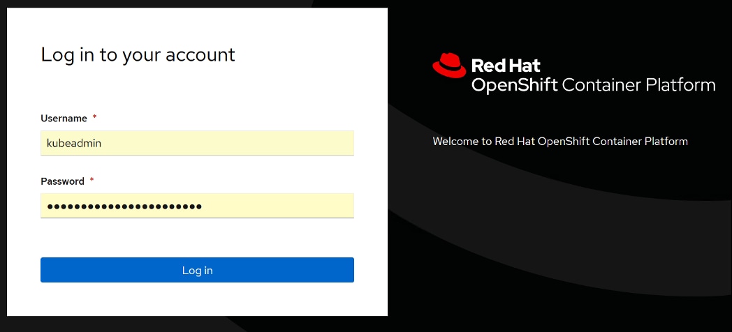
Step 3. Click Compute > Nodes to look at the status of all the nodes in the cluster.
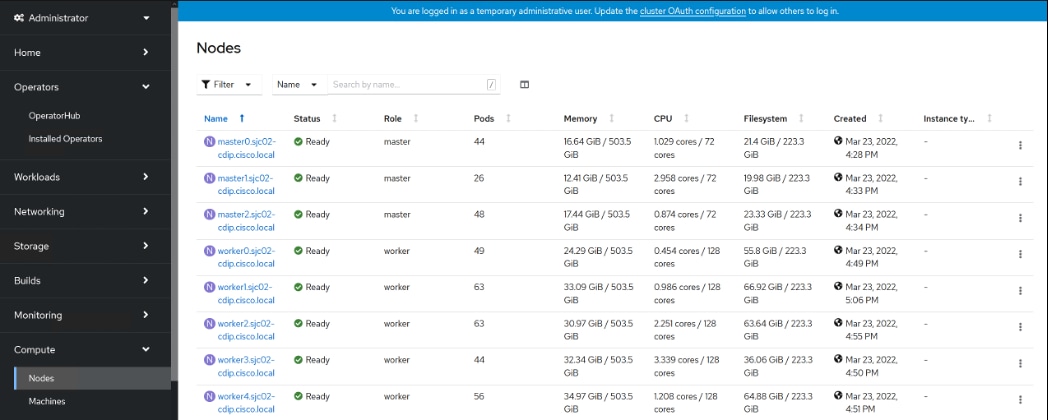
Note: If required to remove worker role from master node run command: # oc patch schedulers.config.openshift.io/cluster --type merge -p '{"spec":{"mastersSchedulable":false}}' scheduler.config.openshift.io/cluster patched
Deploy Red Hat OpenShift Container Storage
This subject contains the following procedures:
● Install Ceph using Red Hat OpenShift Container Storage (OCS) operator
● Set up OCS using Local Storage
● Deploy OpenShift Container Storage
Procedure 1. Install Ceph using Red Hat OpenShift Container Storage (OCS) operator
Ceph is a highly scalable distributed storage solution for block storage, object storage, and shared filesystems.
Rook enables Ceph storage to run on Kubernetes using Kubernetes primitives. With Ceph running in the Kubernetes cluster, Kubernetes applications can mount block devices and filesystems managed by Rook or can use the S3/Swift API for object storage.
In this reference design, Red Hat Ceph is setup and configured to provide persistent volume to CDP Private Cloud Data Services components.
OCS operator is an easy way to deploy Ceph in Red Hat OpenShift. Rook manages and deploy Ceph in OpenShift
The requirements for installing OpenShift Container Storage using local storage devices are as follows:
● The Local Storage Operator version must match the Red Hat OpenShift Container Platform version to have the Local Storage Operator fully supported with Red Hat OpenShift Container Storage. The Local Storage Operator does not get upgraded when Red Hat OpenShift Container Platform is upgraded.
● You must have at least three OpenShift Container Platform worker nodes in the cluster with locally attached storage devices on each of them.
● Each of the three selected nodes must have at least one raw block device available to be used by OpenShift Container Storage.
● The devices you use must be empty; the disks must not include physical volumes (PVs), volume groups (VGs), or logical volumes (LVs) remaining on the disk.
Step 1. Configure OpenShift Container Storage using local storage.
Step 2. Configure Ceph using storage class created in step 1.
Note: The solution highlights steps for Deploying OpenShift Container Storage using bare metal infrastructure. For more detail visit: https://access.redhat.com/documentation/en-us/red_hat_openshift_container_storage/4.8/html/deploying_openshift_container_storage_using_bare_metal_infrastructure/index
Procedure 2. Set up OCS using Local Storage
Step 1. Label nodes that will be used for OpenShift Container Storage by running the following commands.
# oc label nodes <WorkerNodeName> cluster.ocs.openshift.io/openshift-storage=''
Step 2. Label all worker nodes by running the following command.
# oc label nodes worker0.sjc02-cdip.cisco.local cluster.ocs.openshift.io/openshift-storage=''
# oc label nodes worker1.sjc02-cdip.cisco.local cluster.ocs.openshift.io/openshift-storage=''
# oc label nodes worker2.sjc02-cdip.cisco.local cluster.ocs.openshift.io/openshift-storage=''
……
# oc label nodes workern.sjc02-cdip.cisco.local cluster.ocs.openshift.io/openshift-storage=''
Step 3. list node that has that label to verify
# oc get nodes -l cluster.ocs.openshift.io/openshift-storage=
NAME STATUS ROLES AGE VERSION
worker0.sjc02-cdip.cisco.local Ready worker 28d v1.21.11+6b3cbdd
worker1.sjc02-cdip.cisco.local Ready worker 28d v1.21.11+6b3cbdd
worker2.sjc02-cdip.cisco.local Ready worker 28d v1.21.11+6b3cbdd
worker3.sjc02-cdip.cisco.local Ready worker 28d v1.21.11+6b3cbdd
worker4.sjc02-cdip.cisco.local Ready worker 28d v1.21.11+6b3cbdd
Step 4. Login to OpenShift Web Console.
Step 5. Click Operators > Operator Hub in the left pane of the OpenShift Web Console
Step 6. Search or filter results by typing local storage as shown below:
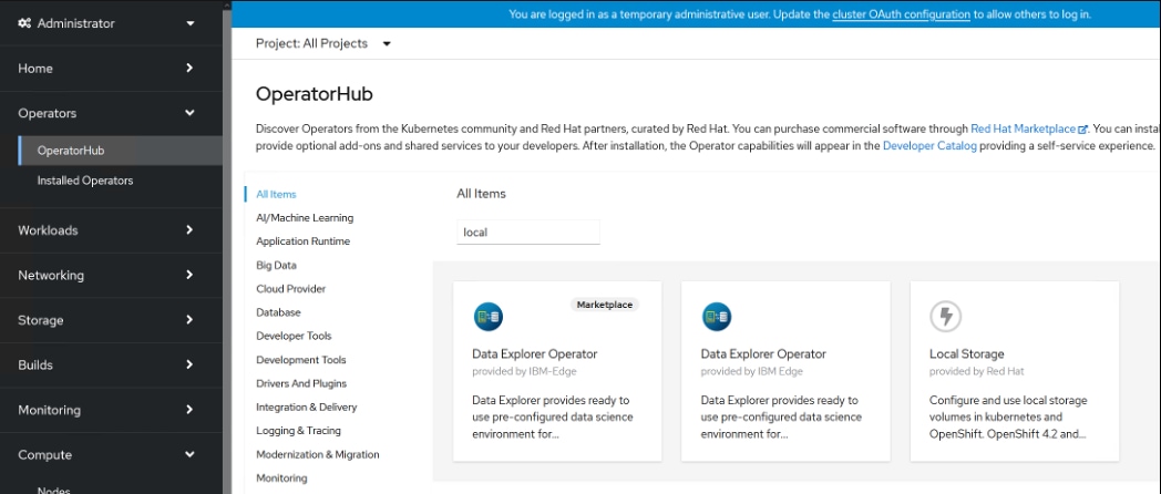
Step 7. Click Local Storage Operator from the filtered list of Operators. Click Install as shown below:
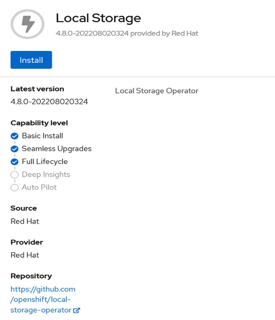
Step 8. Set the following options on the Install Operator page:
a. Update channel as 4.8
b. Installation Mode as “A specific namespace on the cluster”
c. Installed Namespace as Operator recommended namespace “openshift-local-storage”
d. Approval strategy as Automatic
Step 9. Click Install.
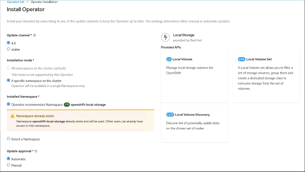
Step 10. Verify Operator install progress by running the following command:
# oc -n openshift-local-storage get pods
NAME READY STATUS RESTARTS AGE
local-storage-operator-5986fb498d-vmg86 1/1 Running 0 25s
# oc get csvs -n openshift-local-storage
NAME DISPLAY VERSION REPLACES PHASE
local-storage-operator.4.8.0-202208020324 Local Storage 4.8.0-202208020324 Succeeded
Step 11. Verify that the Local Storage Operator shows the status as “Succeeded” under Installed Operators.
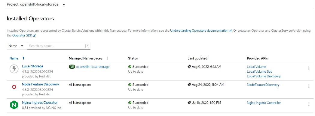
Step 12. Retrieve the Device ID of the disks that will be providing local storage. Login to worker node by running the following command:
# oc debug node/worker0.sjc02-cdip.cisco.local
Starting pod/worker0sjc02-cdipciscolocal-debug ...
To use host binaries, run `chroot /host`
Pod IP: 10.10.1.53
If you don't see a command prompt, try pressing enter.
sh-4.4# lsblk
NAME MAJ:MIN RM SIZE RO TYPE MOUNTPOINT
sda 8:0 0 223.5G 0 disk
|-sda1 8:1 384M 0 part /host/boot
|-sda2 8:2 127M 0 part /host/boot/efi
|-sda3 8:3 1M 0 part
`-sda4 8:4 0 223G 0 part
nvme0n1 259:0 0 7T 0 disk
nvme1n1 259:1 0 7T 0 disk
nvme3n1 259:2 0 7T 0 disk
nvme2n1 259:3 0 7T 0 disk
nvme4n1 259:4 0 7T 0 disk
nvme5n1 259:5 0 7T 0 disk
sh-4.4#
Step 13. Obtain the device id, nvme0n1, nvme1n1… nvmeNn1 from all worker nodes by running the following command:
# oc debug node/worker0.sjc02-cdip.cisco.local
Starting pod/worker0sjc02-cdipciscolocal-debug ...
To use host binaries, run `chroot /host`
Pod IP: 10.10.1.53
If you don't see a command prompt, try pressing enter.
sh-4.4# chroot /host
sh-4.4# ls -l /dev/disk/by-id | grep nvme0n1
lrwxrwxrwx. 1 root root 13 Mar 24 15:30 nvme-UCSC-NVMEHW-H7680_SDM000011972 -> ../../nvme0n1
lrwxrwxrwx. 1 root root 13 Mar 24 15:30 nvme-eui.0000000000000000000cca0b014d0100 -> ../../nvme0n1
sh-4.4 # ls -l /dev/disk/by-id | grep nvme1n1
lrwxrwxrwx. 1 root root 13 Mar 24 11:42 nvme-UCSC-NVMEHW-H7680_SDM00000CD7C -> ../../nvme1n1
lrwxrwxrwx. 1 root root 13 Mar 24 11:42 nvme-eui.0000000000000000000cca0b0137c100 -> ../../nvme1n1
Note: Alternatively, on bastion node with access to all worker node can run following command:
# for i in {0..7}; do ssh core@worker$i.sjc02-cdip.cisco.local ls -l /dev/disk/by-id | grep nvme0n1; done;
# for i in {0..7}; do ssh core@worker$i.sjc02-cdip.cisco.local ls -l /dev/disk/by-id | grep nvme1n1; done;
Step 14. Fill-in the following table with worker nodes and device id of Nvme0n1. In this reference example, we have used nvme0n1 and nvme1n1 to be configured in Local Storage Operator. Add more disk based on your storage requirement.
Table 8. Device ID for the locally installed NVMe to be added in local volume configuration
| Node |
Device |
Device ID |
| worker0.sjc02-cdip.cisco.local |
nvme0n1 |
nvme-UCSC-NVMEHW-H7680_SDM000011972 |
| worker0.sjc02-cdip.cisco.local |
nvme1n1 |
nvme-UCSC-NVMEHW-H7680_SDM00001195E |
| worker1.sjc02-cdip.cisco.local |
nvme0n1 |
nvme-UCSC-NVMEHW-H7680_SDM00000CDD3 |
| worker1.sjc02-cdip.cisco.local |
nvme1n1 |
nvme-UCSC-NVMEHW-H7680_SDM000011990 |
| worker2.sjc02-cdip.cisco.local |
nvme0n1 |
nvme-UCSC-NVMEHW-H7680_SDM00000CDF0 |
| worker2.sjc02-cdip.cisco.local |
nvme1n1 |
nvme-UCSC-NVMEHW-H7680_SDM00000CD82 |
| worker3.sjc02-cdip.cisco.local |
nvme0n1 |
nvme-UCSC-NVMEHW-H7680_SDM00000CDEA |
| worker3.sjc02-cdip.cisco.local |
nvme1n1 |
nvme-UCSC-NVMEHW-H7680_SDM00000CD7C |
| worker4.sjc02-cdip.cisco.local |
nvme0n1 |
nvme-UCSC-NVMEHW-H7680_SDM00000CD5C |
| worker4.sjc02-cdip.cisco.local |
nvme1n1 |
nvme-UCSC-NVMEHW-H7680_SDM00000CDA9 |
Step 15. On the installed Operator page, click Local Storage. On this page, click Create Local Volume.
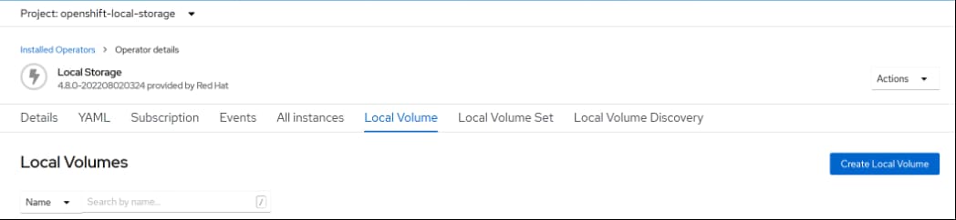
Step 16. Click YAML View and add the following YAML:
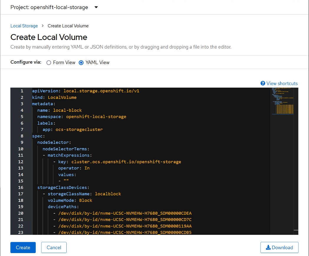
Step 17. Click Create after modifying the YAML View as shown below:
apiVersion: local.storage.openshift.io/v1
kind: LocalVolume
metadata:
name: local-block
namespace: openshift-local-storage
labels:
app: ocs-storagecluster
spec:
nodeSelector:
nodeSelectorTerms:
- matchExpressions:
- key: cluster.ocs.openshift.io/openshift-storage
operator: In
values:
- ""
storageClassDevices:
- storageClassName: localblock
volumeMode: Block
devicePaths:
- /dev/disk/by-id/nvme-UCSC-NVMEHW-H7680_SDM00000CDEA
- /dev/disk/by-id/nvme-UCSC-NVMEHW-H7680_SDM00000CD7C
- /dev/disk/by-id/nvme-UCSC-NVMEHW-H7680_SDM0000119AA
- /dev/disk/by-id/nvme-UCSC-NVMEHW-H7680_SDM00000CDB5
- /dev/disk/by-id/nvme-UCSC-NVMEHW-H7680_SDM00000CDF0
- /dev/disk/by-id/nvme-UCSC-NVMEHW-H7680_SDM00000CD82
- /dev/disk/by-id/nvme-UCSC-NVMEHW-H7680_SDM00000CD5C
- /dev/disk/by-id/nvme-UCSC-NVMEHW-H7680_SDM00000CDA9
- /dev/disk/by-id/nvme-UCSC-NVMEHW-H7680_SDM00000CD9D
- /dev/disk/by-id/nvme-UCSC-NVMEHW-H7680_SDM00000CDAE
Note: devicePaths must be specified as per the device id of your environment captured from steps outlined above. Add devices as per the storage requirements in your environment. For the sake of simplicity, we have added one Nvme disk from each worker node.
Step 18. Verify Local Volume is created with the name specified in YAML, such as local-block in this case.
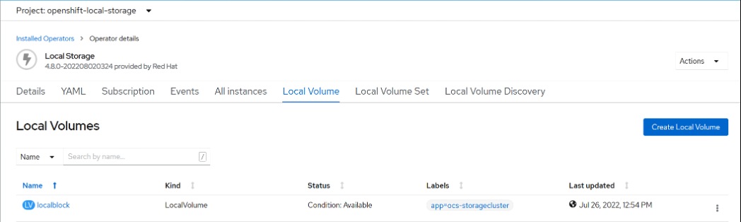
Step 19. Verify if the pods are created and in “running” state before proceeding.
# oc get pods -n openshift-local-storage
local-block-local-diskmaker-4qrfj 1/1 Running 0 2m18s
local-block-local-diskmaker-bfrqb 1/1 Running 0 2m18s
local-block-local-diskmaker-j7jqf 1/1 Running 0 2m18s
local-block-local-diskmaker-r4h6k 1/1 Running 0 2m18s
local-block-local-diskmaker-wlvbv 1/1 Running 0 2m18s
local-block-local-provisioner-dvjb9 1/1 Running 0 2m18s
local-block-local-provisioner-hphv8 1/1 Running 0 2m18s
local-block-local-provisioner-l9fhk 1/1 Running 0 2m18s
local-block-local-provisioner-ntgb6 1/1 Running 0 2m18s
local-block-local-provisioner-r6c4f 1/1 Running 0 2m18s
local-storage-operator-5f946dfb59-57bnf 1/1 Running 0 55m
Step 20. Check if the PVs are created and in Available state.
# oc get pv | grep localblock
local-pv-13681c07 3min19s 7153Gi RWO Delete Bound openshift-storage/ocs-deviceset-localblock-sc-0-data-7rwgbv localblock-sc
local-pv-208c601c 3min19s 7153Gi RWO Delete Bound openshift-storage/ocs-deviceset-localblock-sc-0-data-9hgx6d localblock-sc
local-pv-48819a35 3min19s 7153Gi RWO Delete Bound openshift-storage/ocs-deviceset-localblock-sc-0-data-6gnmz5 localblock-sc
local-pv-4f55372c 3min19s 7153Gi RWO Delete Bound openshift-storage/ocs-deviceset-localblock-sc-0-data-2wf8qf localblock-sc
local-pv-68e16d8c 3min19s 7153Gi RWO Delete Bound openshift-storage/ocs-deviceset-localblock-sc-0-data-0qtspn localblock-sc
local-pv-a83a4f57 3min19s 7153Gi RWO Delete Bound openshift-storage/ocs-deviceset-localblock-sc-0-data-1ghrbx localblock-sc
local-pv-b1d8d288 3min19s 7153Gi RWO Delete Bound openshift-storage/ocs-deviceset-localblock-sc-0-data-8nc9m7 localblock-sc
local-pv-c1b29824 3min19s 7153Gi RWO Delete Bound openshift-storage/ocs-deviceset-localblock-sc-0-data-5rq9d9 localblock-sc
local-pv-dbbafa04 3min19s 7153Gi RWO Delete Bound openshift-storage/ocs-deviceset-localblock-sc-0-data-4wfttj localblock-sc
local-pv-fe685269 3min19s 7153Gi RWO Delete Bound openshift-storage/ocs-deviceset-localblock-sc-0-data-34k7nx localblock-sc
Step 21. Check if storage class is provisioned with the name specified in YAML file under storageClassName such as localblock in this case.
# oc get sc|egrep -e "localblock|NAME"
NAME PROVISIONER RECLAIMPOLICY VOLUMEBINDINGMODE ALLOWVOLUMEEXPANSION AGE
localblock-sc kubernetes.io/no-provisioner Delete WaitForFirstConsumer false 6m22s
Procedure 3. Deploy OpenShift Container Storage
Step 1. Login to OpenShift Web Console.
Step 2. Click Operators >Operator Hub in the left pane of the OpenShift Web Console.
Step 3. Search or filter for Ceph.
Step 4. Click OpenShift Container Storage.
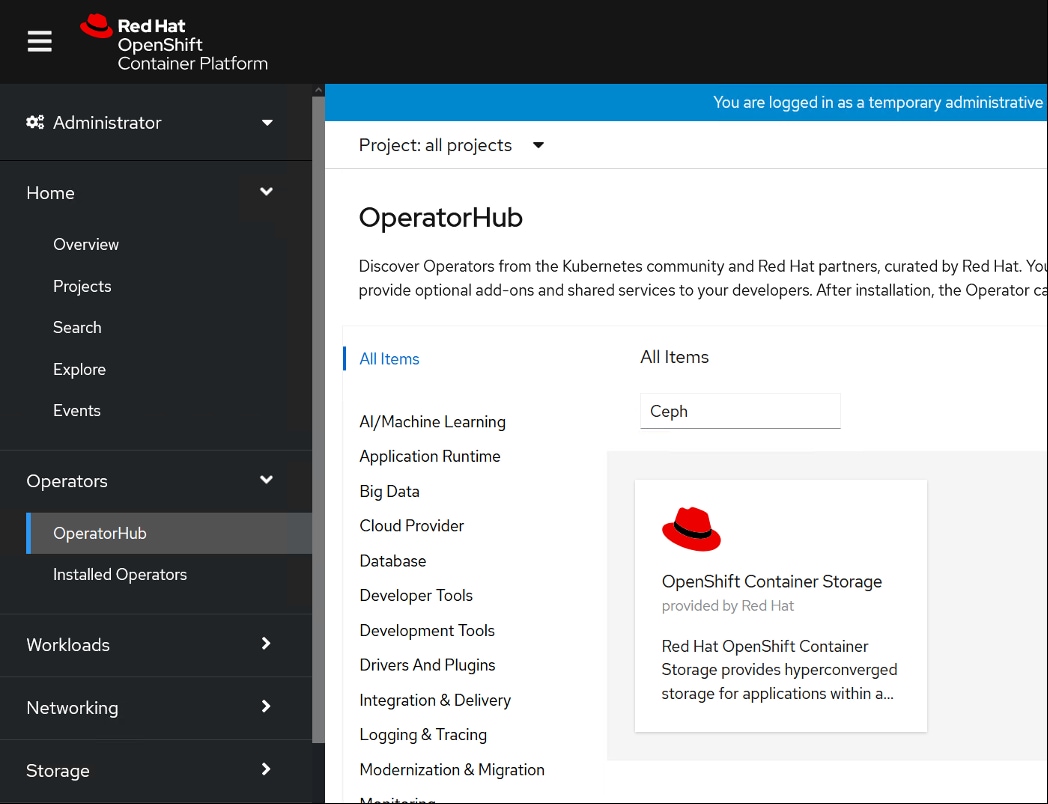
Step 5. Click Install.
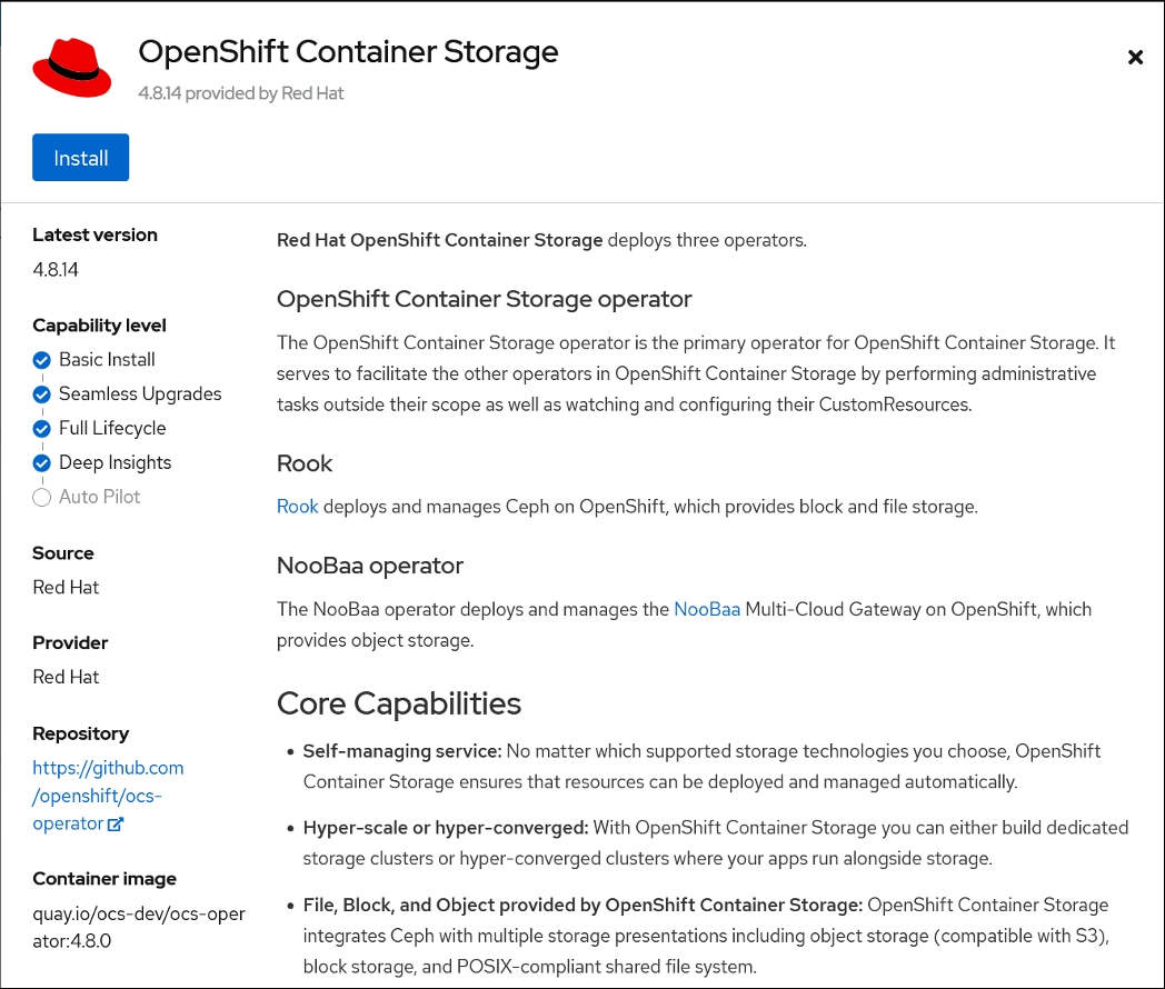
Step 6. Provide the following:
a. Select Update Channel. Such as stable-4.8 in this example.
b. Installation Mode to be “A specific namespace on the cluster.”
c. Select Operator recommended namespace. Or you can create a namespace of your choice prior and select it here.
d. Click Install.
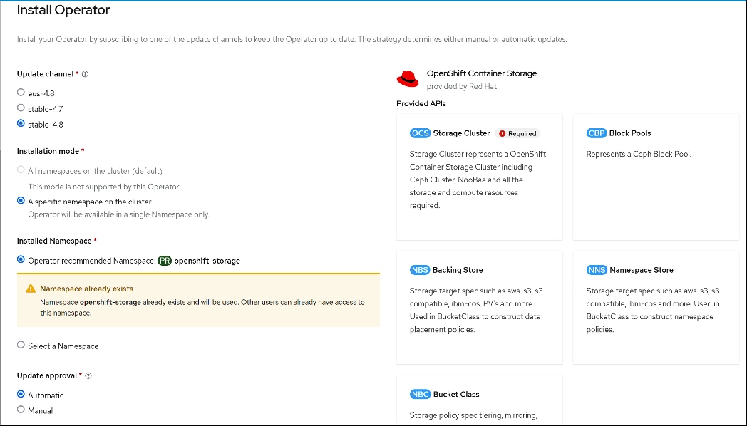
Step 7. Follow the progress of the Operator install as shown below:
Step 8. Once installed the status should display as Succeeded.
Step 9. Verify Pod status by running the following CLI commands:
# oc -n openshift-storage get pods
NAME READY STATUS RESTARTS AGE
noobaa-operator-b8d69c487-xk57n 1/1 Running 0 61m
ocs-metrics-exporter-544b446f54-2vmrs 1/1 Running 0 61m
ocs-operator-86b854b7b7-t22gb 1/1 Running 0 61m
rook-ceph-operator-8bc5f8586-dzjg6 1/1 Running 0 61m
# oc get csvs -n openshift-storage
NAME DISPLAY VERSION REPLACES PHASE
nfd.4.8.0-202208020324 Node Feature Discovery 4.8.0-202208020324
Succeeded
nginx-ingress-operator.v0.5.1 Nginx Ingress Operator 0.5.1 nginx-ingress-operator.v0.5.0 Succeeded
ocs-operator.v4.8.14 OpenShift Container Storage 4.8.14 Succeeded
Step 10. In the Installed Operator page, click Storage Cluster and then click Create Storage Cluster.
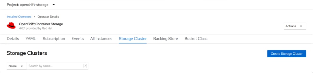
Step 11. Provide the following:
a. Select Internal-Attached Devices for Select Mode.
b. For Capacity, select “localblock” storage class in the dropdown. This localblock storage class was created in earlier steps while creating OCS for local storage.
c. Select Nodes. Click Create.
Step 12. This will create various PODs in the namespace provided during creation. Verify all PODs are in running state via either CLI or in Web Console as shown below:
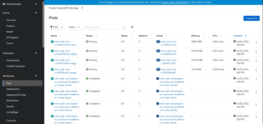
Step 13. Verify if storage classes have been successfully created by running the following oc command:
# oc get sc
NAME PROVISIONER RECLAIMPOLICY VOLUMEBINDINGMODE ALLOWVOLUMEEXPANSION AGE
localblock-sc kubernetes.io/no-provisioner Delete WaitForFirstConsumer false 36d
localdisk-sc kubernetes.io/no-provisioner Delete WaitForFirstConsumer false 36d
nfs k8s-sigs.io/nfs-subdir-external-provisioner Delete Immediate true 6d
ocs-storagecluster-ceph-rbd openshift-storage.rbd.csi.ceph.com Delete Immediate true 36d
ocs-storagecluster-ceph-rgw openshift-storage.ceph.rook.io/bucket Delete Immediate false 36d
ocs-storagecluster-cephfs openshift-storage.cephfs.csi.ceph.com Delete Immediate true 36d
openshift-storage.noobaa.io openshift-storage.noobaa.io/obc Delete Immediate false 36d
Step 14. On WebConsole for OpenShift > Overview > Persistent Storage shows health status, see Monitoring OpenShift Container Storage:
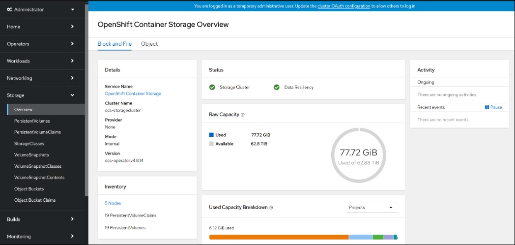
Step 15. Assign default storage class to configured for Cloudera Private Cloud Data Services:
# oc patch storageclass ocs-storagecluster-ceph-rbd -p '{"metadata": {"annotations": {"storageclass.kubernetes.io/is-default-class": "true"}}}'
storageclass.storage.k8s.io/ocs-storagecluster-ceph-rbd patched
# oc get sc
NAME PROVISIONER RECLAIMPOLICY VOLUMEBINDINGMODE ALLOWVOLUMEEXPANSION AGE
localblock-sc kubernetes.io/no-provisioner Delete WaitForFirstConsumer false 36d
localdisk-sc kubernetes.io/no-provisioner Delete WaitForFirstConsumer false 36d
nfs k8s-sigs.io/nfs-subdir-external-provisioner Delete Immediate true 6d
ocs-storagecluster-ceph-rbd (default) openshift-storage.rbd.csi.ceph.com Delete Immediate true 36d
ocs-storagecluster-ceph-rgw openshift-storage.ceph.rook.io/bucket Delete Immediate false 36d
ocs-storagecluster-cephfs openshift-storage.cephfs.csi.ceph.com Delete Immediate true 36d
openshift-storage.noobaa.io openshift-storage.noobaa.io/obc Delete Immediate false 36d
Step 16. Create a test persistent volume from the Ceph storage cluster created from the operator. Create a persistent volume by using the following YAML file:
kind: PersistentVolumeClaim
apiVersion: v1
metadata:
name: test-pvc
spec:
storageclass: ocs-storagecluster-ceph-rbd
accessModes:
- ReadWriteOnce
resources:
requests:
storage: 10Gi
Step 17. Create a POD and mount that persistent volume using the following YAML file:
apiVersion: v1
kind: Pod
metadata:
name: ceph-pv-pod
spec:
volumes:
- name: ceph-pv-storage
persistentVolumeClaim:
claimName: test-pvc
containers:
- name: ceph-pv-container
image: nginx
ports:
- containerPort: 80
name: "http-server"
volumeMounts:
- mountPath: "/mnt/ceph"
name: ceph-pv-storage
Step 18. Go to the POD terminal and run the following:
# touch /mnt/ceph/a.txt
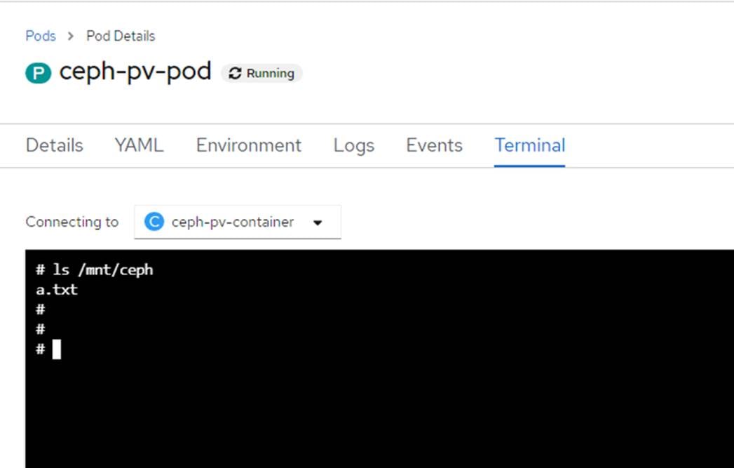
Step 19. Delete the container and recreate and verify that the file created in previously deleted “ceph-pv-pod” is available in newly created persistent volume.
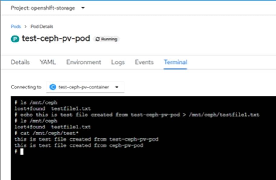
Install and Configure Cloudera Private Cloud
This chapter contains the following:
● Cloudera Data Platform Private Cloud Base Requirements
● Install CDP Private Cloud Data Services
Review the installation requirements and core tasks for installing CDP Private Cloud. CDP Private Cloud Data Services works on top of CDP Private Cloud Base and is the on-premises offering of CDP that brings many of the benefits of the public cloud deployments to the on-premise CDP deployments. CDP Private Cloud Data Services lets you deploy and use the Cloudera Data Warehouse (CDW), Cloudera Machine Learning (CML) and Cloudera Data Engineering (CDE).
You must install CDP Private Cloud Data Services on an existing deployment of CDP Private Cloud Base. To install CDP Private Cloud, you need an isolated hardware environment with dedicated infrastructure and networking. CDP Private Cloud Data Services uses containers on the Red Hat OpenShift Container Platform.
CDP Private Cloud Base provides the following components and services that are used by CDP Private Cloud Data Services:
● SDX Data Lake cluster for security, metadata, and governance
● HDFS or Ozone for storage
● Cloudera Runtime components such as Ranger, Atlas, and Hive Metastore (HMS). Atlas requires HBase and Kafka should be setup earlier
● CDP license is must
● All CDP Private Cloud Base services should be in good health
● Networking infrastructure that supports network traffic between storage and compute environments
Before you get started with the CDP PC Data Services installation, please review the hardware and software requirements and the pre-installation checklist for installing CDP PvC Data Services on OpenShift or Installing CDP PvC Data Services on Embedded Container Service (ECS).
Note: This CVD focuses on installing CDP Private Cloud Data Services version 1.4.0 on OpenShift version 4.8.x. Please refer to the latest install guide for up-to-date support on software and versioning for various components of CDP Private Cloud Data Services.
Cloudera Data Platform Private Cloud Base Requirements
Configure CDP PvC Base and Cloudera Manager in preparation for the CDP Private Cloud Data Services installation as highlighted in the CDP PvC Base requirements: https://docs.cloudera.com/cdp-private-cloud-data-services/1.4.0/installation/topics/cdppvc-installation-cdp-data-center.html
Auto-TLS is managed using the certmanager utility, which is included in the Cloudera Manager Agent software, and not the Cloudera Manager Server software. You must install the Cloudera Manager Agent software on the Cloudera Manager Server host to be able to use the utility. You can use certmanager to manage auto-TLS on a new installation. For more information, go to: Configuring TLS Encryption for Cloudera Manager Using Auto-TLS
Procedure 1. Enable AutoTLS
Step 1. The certmanager syntax is as follows:
/opt/cloudera/cm-agent/bin/certmanager [OPTIONS] COMMAND [ARGS]...
# export JAVA_HOME=/usr/java/jdk-11.0.13; /opt/cloudera/cm-agent/bin/certmanager setup --configure-services
INFO:root:Logging to /var/log/cloudera-scm-agent/certmanager.log
Step 2. The certificates, keystores, and password files generated by auto-TLS are stored in /var/lib/cloudera-scm-agent/agent-cert on each Cloudera Manager Agent.
# cd /var/lib/cloudera-scm-agent/agent-cert/
# ls -ll
total 12
-rw-r--r-- 1 cloudera-scm cloudera-scm 1233 Jan 12 10:35 cm-auto-global_truststore.jks
-rw------- 1 cloudera-scm cloudera-scm 4352 Jan 12 10:35 cm-auto-host_keystore.jks
Step 3. Restart Cloudera Manager Server.
# systemctl restart cloudera-scm-server
Cloudera Manager provides a wizard for integrating your organization’s Kerberos with your cluster to provide authentication services. Cloudera Manager clusters can be integrated with MIT Kerberos, Red Hat Identity Management (or the upstream FreeIPA), or Microsoft Active Directory. For more information, see Enable Kerberos Authentication for CDP.
Note: In our lab, we configured Active-Directory based Kerberos authentication. We presume that Active Directory is pre-configured with OU, user(s) and proper authentication is setup for Kerberos Authentication. LDAP users and bind users are expected to be in the same branch/OU.
Note: Before integrating Kerberos with your cluster, configure TLS encryption between Cloudera Manager Server and all Cloudera Manager Agent host systems in the cluster. During the Kerberos integration process, Cloudera Manager Server sends keytab files to the Cloudera Manager Agent hosts, and TLS encrypts the network communication, so these files are protected.
Note: For Active Directory setup, you must have access to AD instance for initial setup or for on-going management, or you will need help from your AD administrator.
Procedure 1. Verify Kerberos Setup
Step 1. Verify by running the following command that Kerberos is properly setup within your AD environment prior to setup KDC in Cloudera Manager or for troubleshooting purposes:
# kinit cdpbind@SJC02-CDIP.CISCO.LOCAL
Password for cdpbind@SJC02-CDIP.CISCO.LOCAL:
# klist
Ticket cache: FILE:/tmp/krb5cc_0
Default principal: cdpbind@SJC02-CDIP.CISCO.LOCAL
Valid starting Expires Service principal
04/21/2022 18:30:48 04/22/2022 04:30:48 krbtgt/SJC02-CDIP.CISCO.LOCAL@SJC02-CDIP.CISCO.LOCAL
renew until 04/28/2022 18:30:45
Procedure 2. Enable Kerberos
Step 1. In Cloudera manager console select setup a KDC. Click Continue.
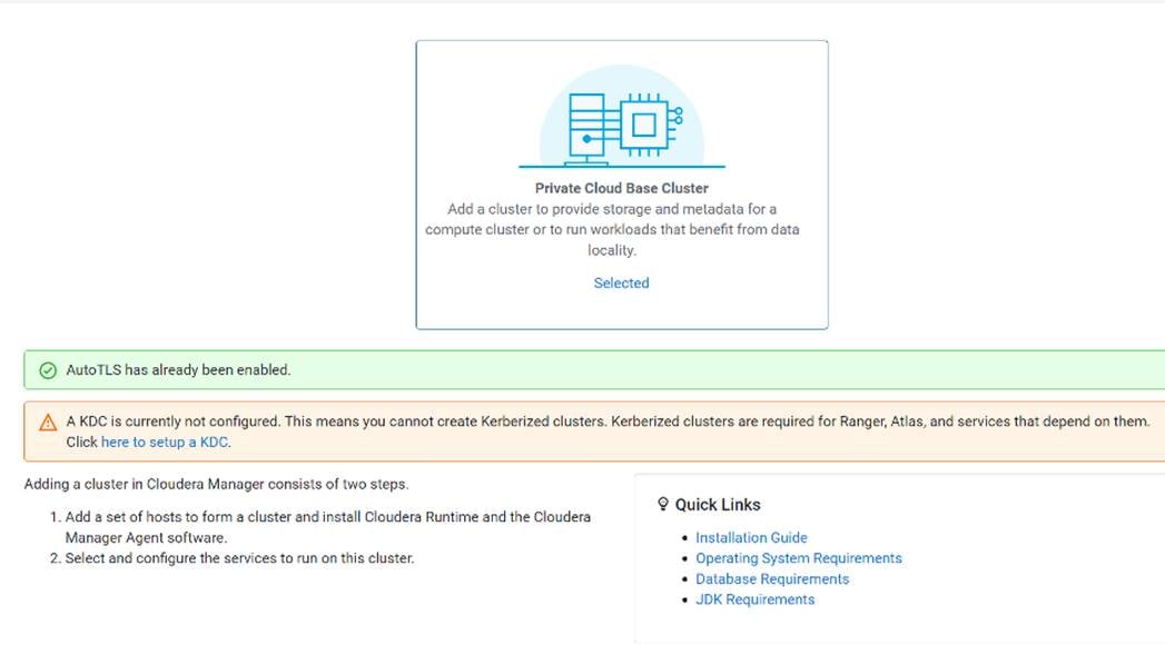
Step 2. Select Active Directory as shown below.
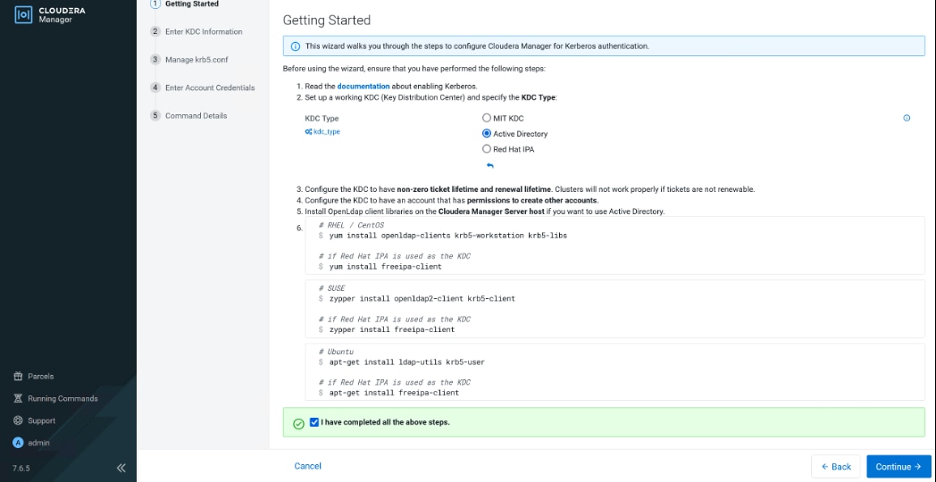
Step 3. As recommended above, install the following in all Cloudera Manager hosts by running the below command. Once completed, click the checkbox “I have completed all the above steps” and click Continue.
# ansible all -m command -a "yum install -y openldap-clients krb5-workstation krb5-libs"
Step 4. Enter KDC information for this Cloudera Manager. Use the following table as an example to fill up the KDC setup information:
| Component |
Value |
| Kerberos Security Realm |
SJC02-CDIP.CISCO.LOCAL |
| KDC Server Host |
e26-winjb.sjc02-cdip.cisco.local |
| KDC Admin Server Host |
e26-winjb.sjc02-cdip.cisco.local |
| Active Directory Suffix |
OU=cdp_kerberos,DC=sjc02-cdip,DC=cisco,DC=local |
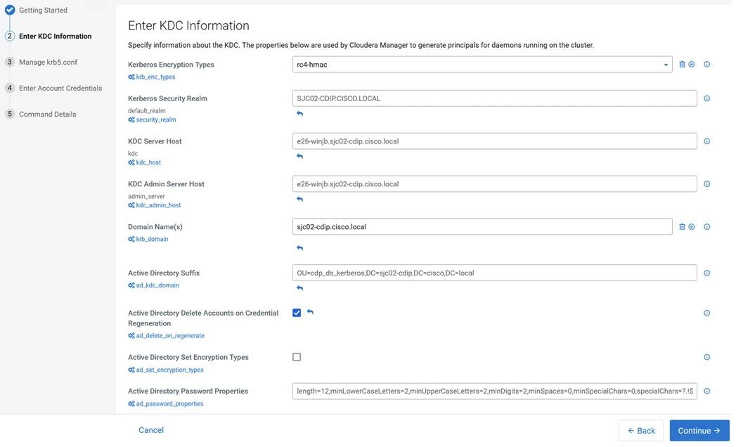
Note: In this setup, we used Kerberos authentication with Active Directory (AD). Setting up AD is beyond the scope of this document.
Step 5. Check the box for Manage krb5.conf through Cloudera Manager. This will install krb5.conf file in all the hosts selected for data lake.
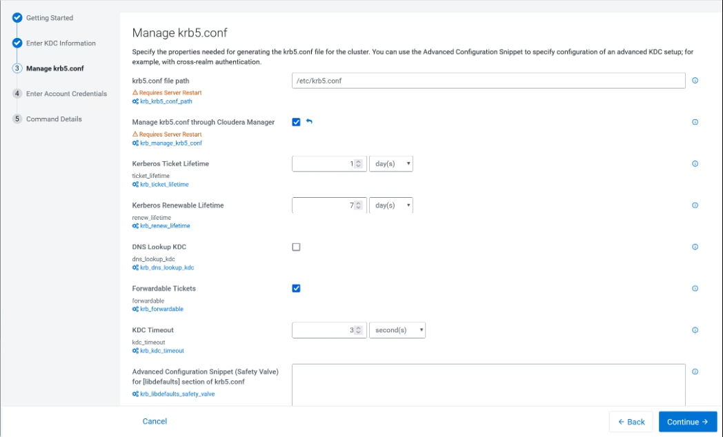
Step 6. Enter account credentials for the bind user which you have created in AD. This credential will be used to create service accounts in AD. In our lab setup, cdpbind user is created in AD for this purpose.
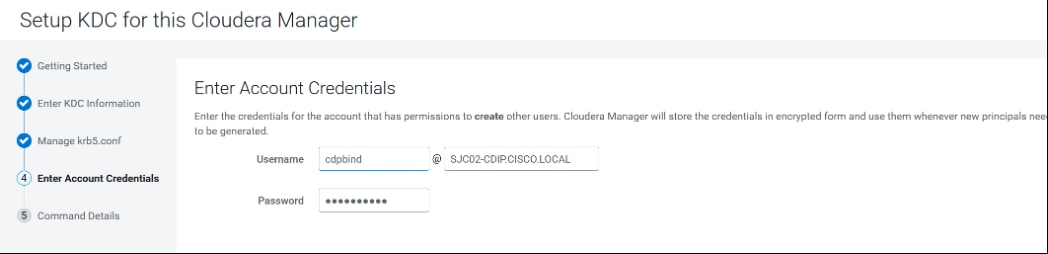
Step 7. Click Continue.
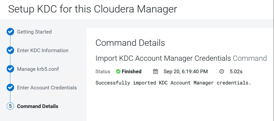
Step 8. Click Finish to complete the KDC setup.
Once setting up KDC is completed, the Cloudera Manager wizard for adding a cluster will reflect the following:
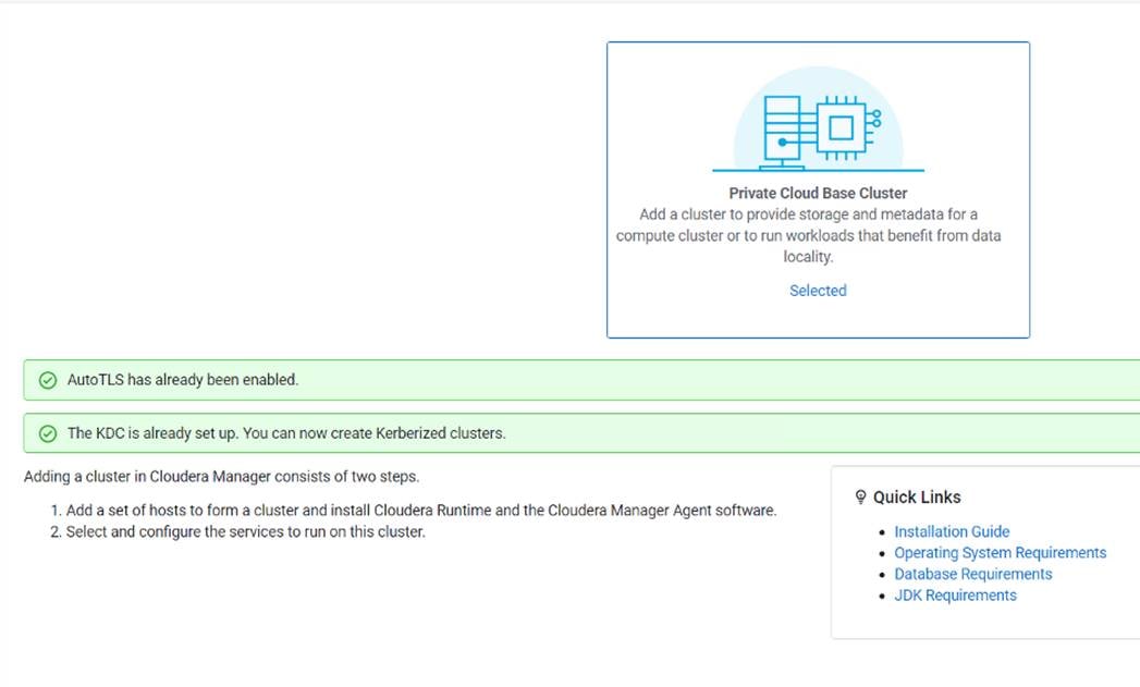
Step 9. Configure Cloudera Manager with a JKS-format (not PKCS12) TLS truststore. For configuration steps, see Database requirements.
Step 10. Configure Cloudera Manager to include a root certificate that trusts the certificate for all Cloudera Manager server hosts expected to be used with Private Cloud. Import the necessary certificates into the truststore configured in Configure Administration > Settings > Security > Cloudera Manager TLS/SSL Client Trust Store File.
Note: This requires a Cloudera Manager restart.
Step 11. Configure Ranger and LDAP for user authentication. Ensure that you have configured Ranger user synchronization. For configuration steps, see Configure Ranger authentication for LDAP and Ranger usersync.
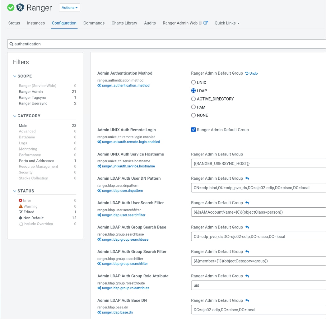
Step 12. Configure LDAP using Cloudera Manager.
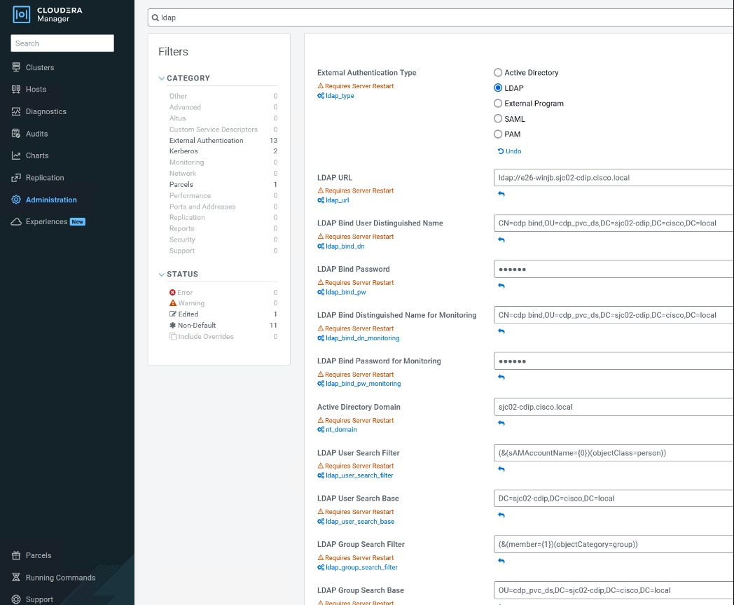
Note: Only Microsoft Active Directory (AD) and OpenLDAP are currently supported.
Step 13. For configuration steps, see Configure authentication using an LDAP-compliant identity service.
Note: Restart Cloudera Manager and other services as required.
Install CDP Private Cloud Data Services
This subject contains the following procedures:
● Install CDP Private Cloud Data Service on Red Hat OpenShift Container Platform
Procedure 1. Install CDP Private Cloud Data Service on Red Hat OpenShift Container Platform
Step 1. Log into Cloudera Manager WebUI <https://FQDN_or_IP>:7183/. Click the Private Cloud in the left pane. This will open the Private Cloud installation wizard. This wizard will walk you through the steps to install CDP Private Cloud. Select Data Services tab from left side navigation menu.
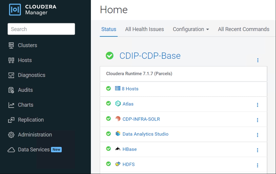
Step 2. From the Getting Started page, in other Options, select click here to install CDP PvC Data Services on Red Hat OpenShift cluster.
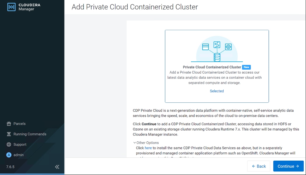
Step 3. Select the repository that contains the installer. Select Repository field is pre-populated with Cloudera download location. If you have setup custom repository, it can also be chosen. Click Next.
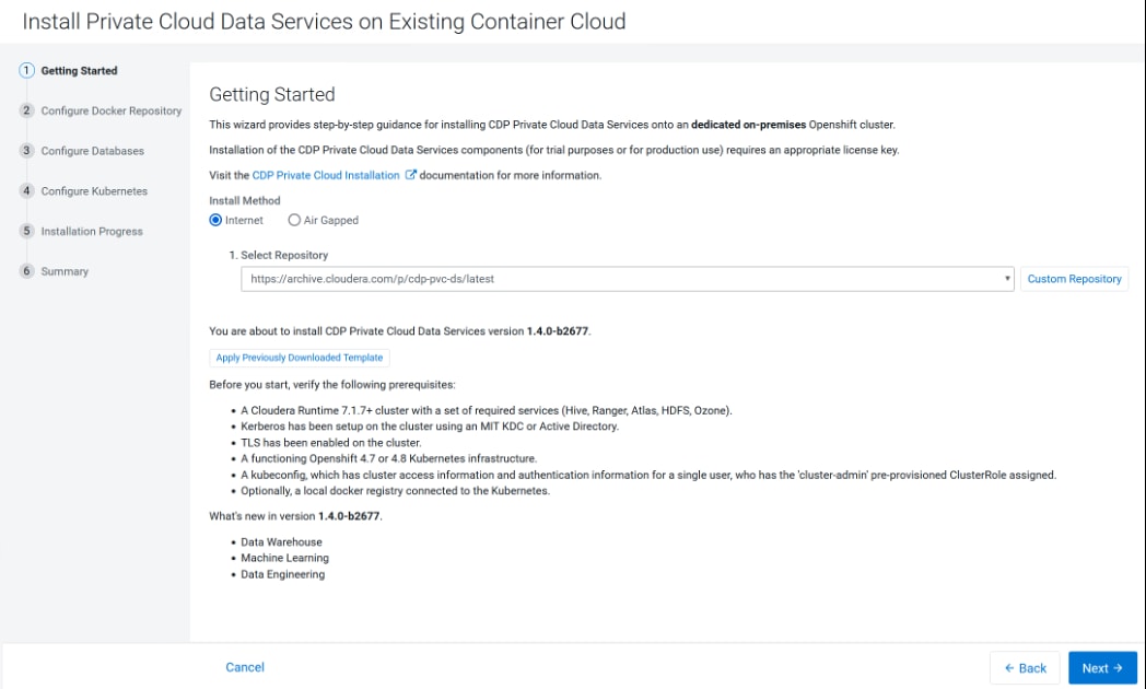
Step 4. From Configure Docker Registry step, select “Use Cloudera’s default Docker Repository.” Click Next.
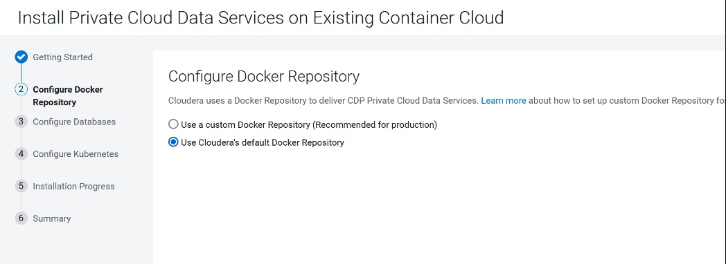
Step 5. Under Configure Databases page, select “Create embedded databases.” Use default 200 GiB for Embedded Database Disk Space. This is the space allocated for embedded PostgreSQL. Default value is 200 GiB and it can be increased depending on environment. Click Next.
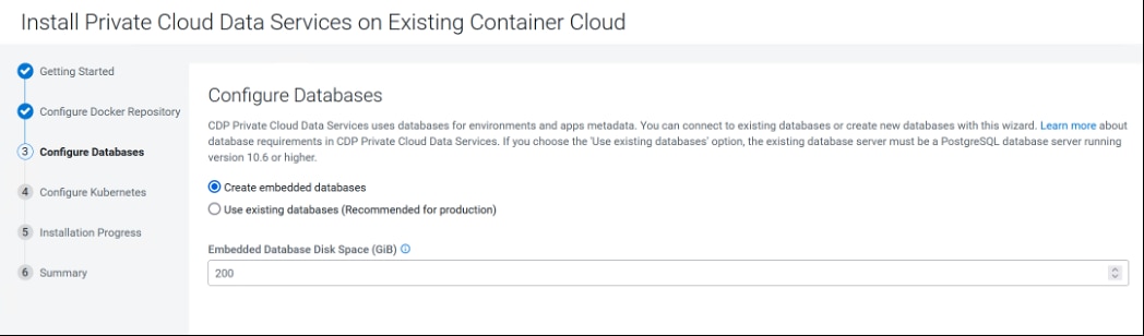
Note: For production environment, recommended to configure an existing database.
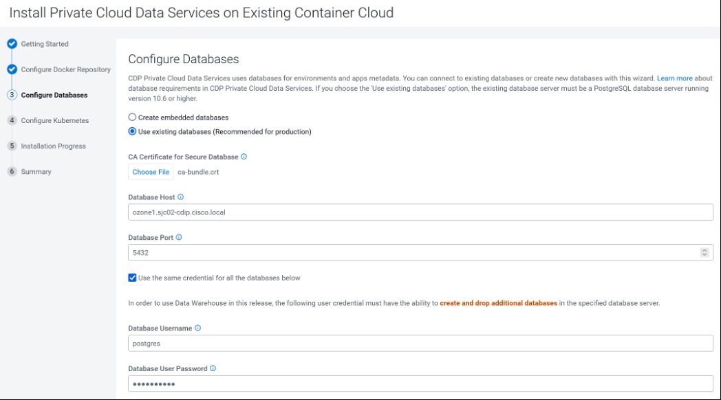
Step 6. In Configure Kubernetes screen, do the following:
a. Click Choose File to upload Kubeconfig file generated by OpenShift install. This Kubeconfig file can be obtained in Bastion server in ~/<OCP install dir>/auth folder.
b. In Kubernetes Namespace, provide a name of CDP PC control plane. This will be reflected as a project in OpenShift.
c. For Configure vault, select Embedded Vault. Vault is a secret management tool. With embedded vault, installer will create a separate project (Namespace) in RHOCP environment for secret management. Already existing or external vault can also be utilized; however, it is beyond the scope of the guide. External vault is recommended solution for production grade environment
d. Specify storage class name “ocs-storagecluster-ceph-rbd” to provide persistent storage to CDP PC control plane containers.
e. Click Next to install private cloud.
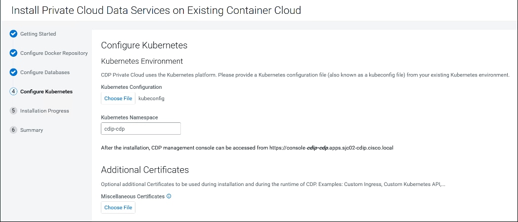
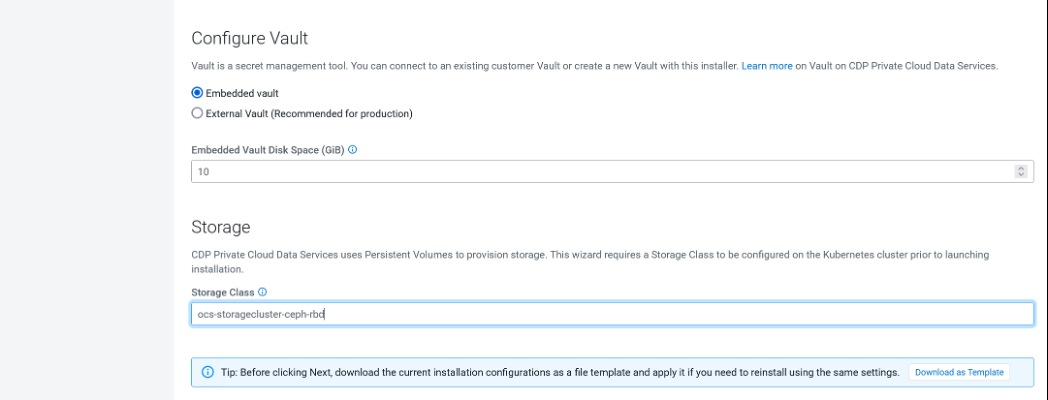
Step 7. Click Next and monitor install steps.
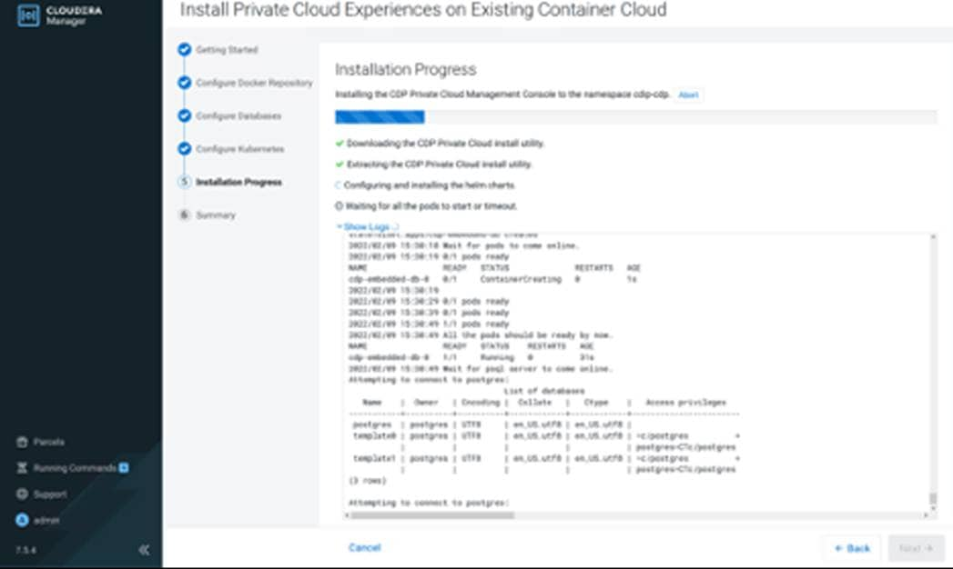
Step 8. Once installation is complete, click Next.
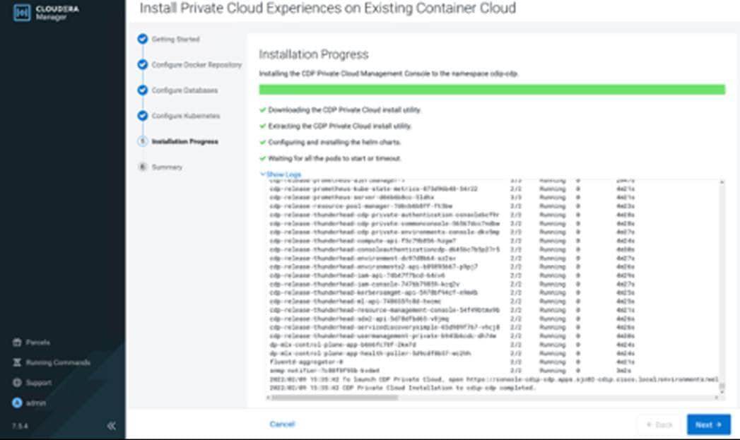
Step 9. Click Launch Private Cloud.
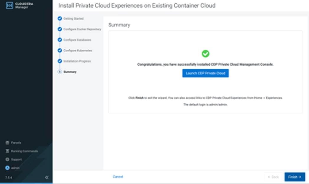
Step 10. Alternatively, from Cloudera Manager > Data Services tab. Click “Open CDP Private Cloud Data Services.”
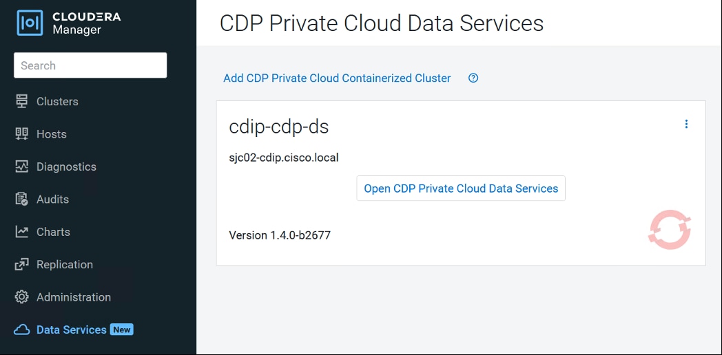
Step 11. Login as LDAP user or local administrator. The default local administrator username and password is admin/admin.
Note: LDAP user role needs to be updated in order to create or configure workload via CDP Private Cloud management console. Please login as local administrator and edit roles.
Step 12. CDP Private Cloud Data Services with various options. Click Management Console to add environment.
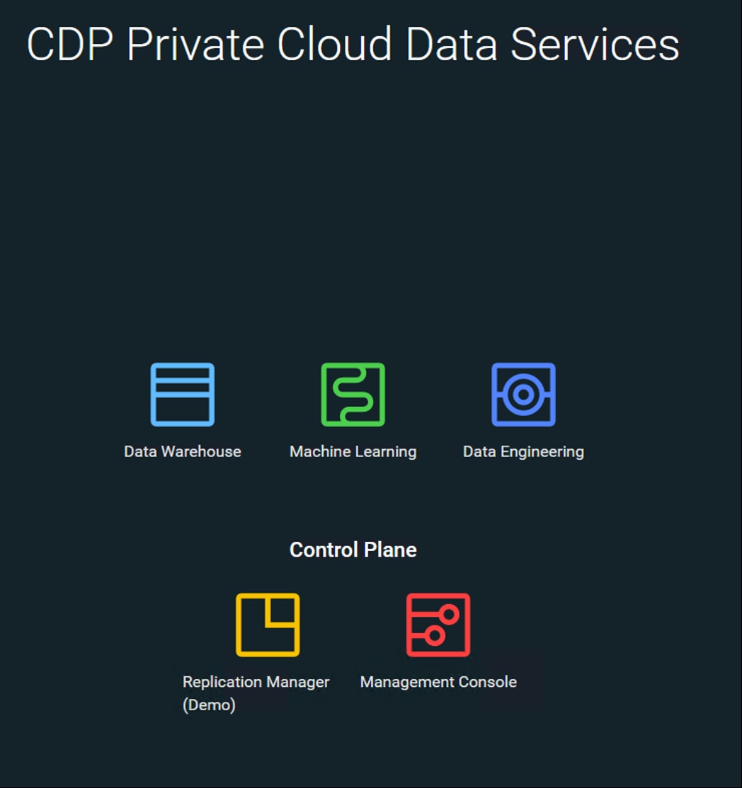
Step 13. Management console dashboard launches.
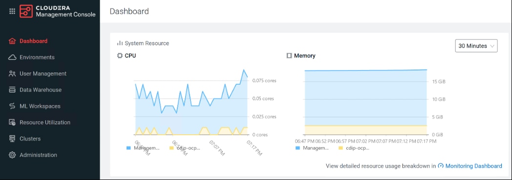
Step 14. Reset default administrator password by selecting administration > Authentication > Local Admin Account.
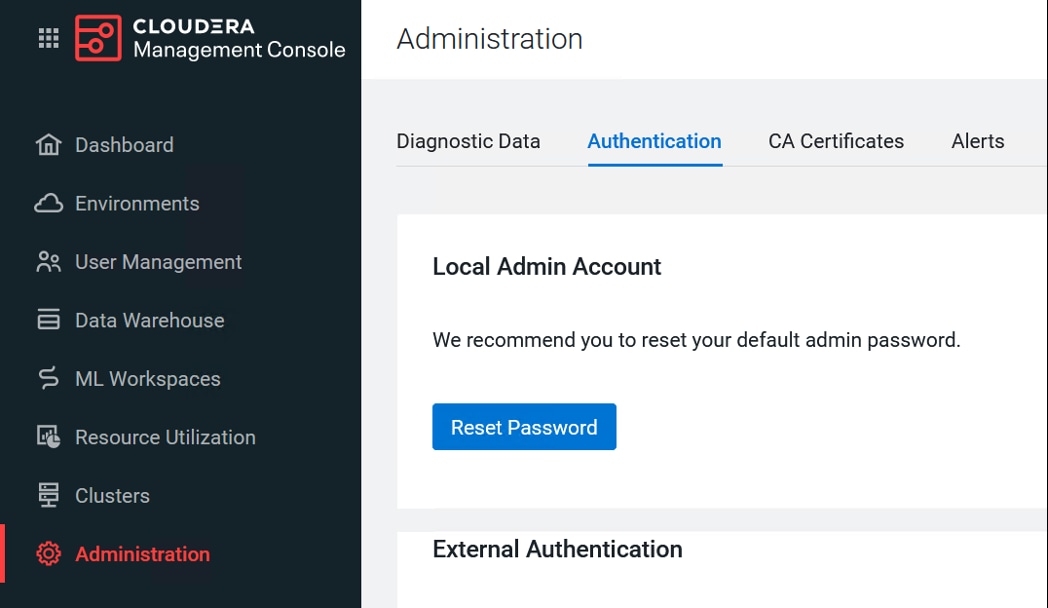
Procedure 2. Register Environment
In CDP, a private cloud environment is an association between a data lake and multiple compute resources.
Note: You can register as many environments as you require.
An environment is a local construct that groups resources such as Machine Learning workspaces or Data Warehouse warehouses within a data center or cloud region. Each environment talks to one SDX residing in a base cluster. For private cloud environments, resources include compute clusters such as Kubernetes as well as Data Lake clusters in CDP. These resources typically reside within the same physical location to minimize network latencies between compute and storage. Compute workloads are deployed within these environments.
A workload receives access to a Kubernetes cluster for compute purposes and a Data Lake cluster for storage, metadata, and security purposes within the environment in which it is deployed. Admins can define user permissions and set resource quotes in each environment.
Step 1. In Cloudera Management Console, click Environments > Register Environment.
Step 2. Enter the Environment Name, Kubernetes Configuration file, Storage Class, Domain, Cloudera Manager URL and admin user and password.
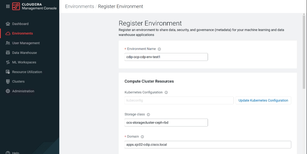
Step 3. Choose cluster from the drop-down list. Click Register after a successful connection.
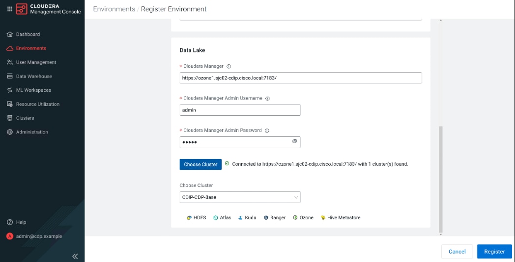
Step 4. Select the registered environment and select Data Lake tab to view details about Data Lake.
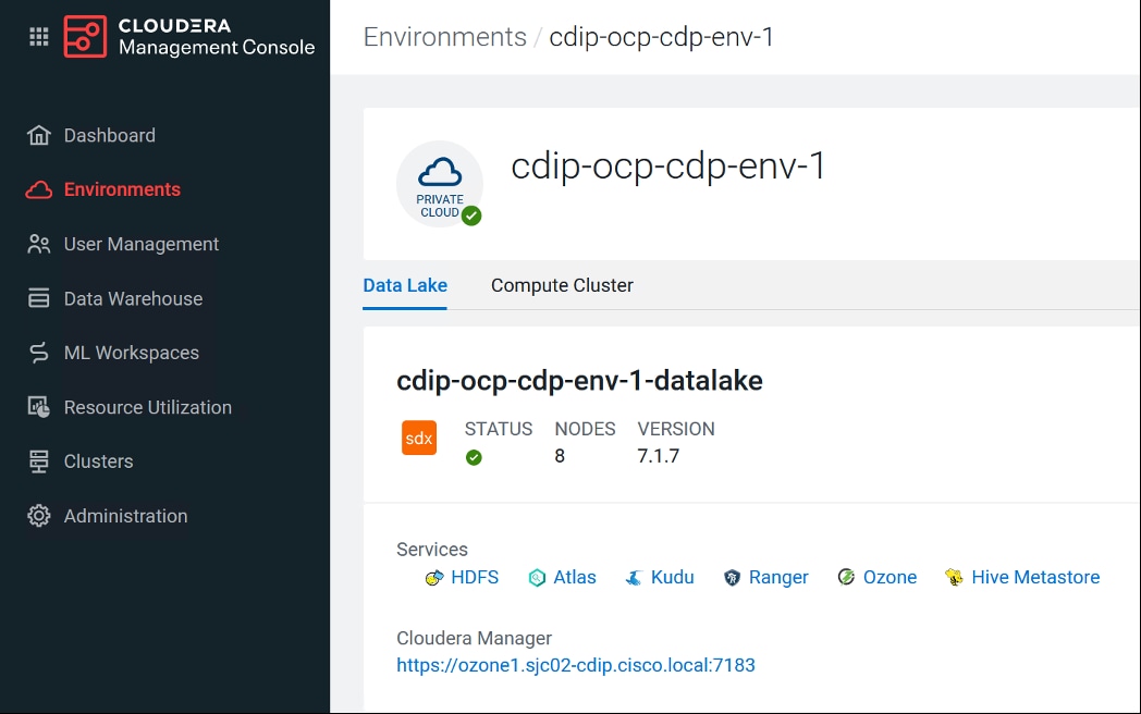
Step 5. Click Compute Cluster tab to view OpenShift environment details.
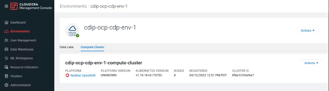
Step 6. Click User Management tab to update LDAP authenticated user and group role(s).
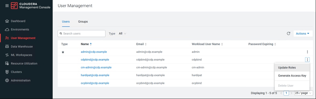
Step 7. Add CA certificate for secure connection using SSL/TLS.
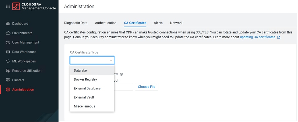
Cloudera Machine Learning (CML)
This chapter contains the following:
● Enable GPUs for Cloudera Machine Learning
● NVIDIA GPU Operator in RedHat OpenShift Container Platform
● GPU Node Setup with Cloudera Machine Learning
Cloudera Machine Learning (CML) is Cloudera’s cloud-native service for machine learning and AI built for CDP Private Cloud. Cloudera Machine Learning unifies self-service data science and data engineering in a single, portable service as part of an enterprise data cloud for multi-function analytics on data anywhere.
Organizations can now build and deploy machine learning and AI capabilities for business at scale, efficiently and securely. Cloudera Machine Learning on Private Cloud is built for the agility and power of cloud computing but operates inside your private and secure data center. The CML service provisions clusters, also known as ML workspaces, which run natively on Kubernetes.
Note: Please review the Cloudera Machine Learning requirements: https://docs.cloudera.com/machine-learning/1.4.0/private-cloud-requirements/index.html
Note: NFS is a requirement for provisioning Machine Learning workspaces. Setting up NFS is beyond the scope of this document. NFS share is used for storing project files for CML workspace. Each CML workspace requires NFS share.
Note: For lab purpose and for the sake of simplicity, we installed and setup NFS server on RHEL bare metal server and exported the file system for remote access. NFS is already setup in many enterprises in some form or the other and it can also be utilized for this purpose as long as it is accessible from private cloud and RHOCP.
Note: It is recommended to use Kubernetes internal NFS. Internal NFS provides cloud like experience and NFS backed persistent volume lifecycle is managed by K8. This can be implemented with dynamic NFS provisioning within RHOCP environment. Persistent volume with NFS lets you setup a managed resource within the cluster which is accessed via the NFS.
Note: To learn more about persistent storage using NFS in RHOCP, go to: https://docs.openshift.com/container-platform/4.8/storage/persistent_storage/persistent-storage-nfs.html
Note: For detailed NFS requirement for CML on Cloudera Private Cloud visit: https://docs.cloudera.com/machine-learning/1.4.0/private-cloud-requirements/topics/ml-pvc-nfs.html
Note: For detailed NFS requirement for CML with RHOCP visit: https://docs.cloudera.com/machine-learning/1.4.0/private-cloud-requirements/topics/ml-pvc-requirements.html
There are some limitations to keep in mind when you are working with Cloudera Machine Learning on Private Cloud.
The following features are not yet supported in CML Private Cloud:
● Logging is limited, and diagnostic bundles for each workspace cannot be downloaded from the workspace UI. Instead, diagnostic bundles for the entire cluster can be downloaded from the control plane.
● Monitoring on Private Cloud does not support node-level resource metrics, hence only K8s Cluster and K8s Container dashboards are available.
● ML Runtimes are not supported.
● CML does not support the NVIDIA Multi-Instance GPU (MIG) feature.
Enable GPUs for Cloudera Machine Learning
A GPU is a specialized processor that can be used to accelerate highly parallelized compute intensive workloads. NVIDIA GPU provides hardware acceleration and well-suited for AI/ML/DL workloads with boost in overall AI-lifecycle. Ideally, CPUs and GPUs should be used in tandem for data engineering and data science workloads. A typical machine learning workflow involves data preparation, model training, model scoring, and model fitting. E general-purpose CPUs for each stage of the workflow, and optionally accelerate selective application through special-purpose GPUs. For example, GPUs allow you to accelerate model fitting using frameworks such as TensorFlow, PyTorch, and Keras.
By enabling GPU support, data scientists can share GPU resources available on Cloudera Machine Learning workspaces. Users can request a specific number of GPU instances, up to the total number available, which are then allocated to the running session or job for the duration of the run or job completion.
Note: NVIDIA GPU edition comes with CUDA 11.1 preinstalled.
If you are using a Legacy Engine, to enable GPU usage on Cloudera Machine Learning, select GPUs when you are provisioning the workspace. https://docs.cloudera.com/machine-learning/1.4.0/gpu/topics/ml-gpu-legacy-engines.html
NVIDIA GPU Operator in RedHat OpenShift Container Platform
The NVIDIA GPU Operator uses the operator framework within Kubernetes to automate the management of all NVIDIA software components needed to provision GPU. These components include the NVIDIA drivers (to enable CUDA), Kubernetes device plugin for GPUs, the NVIDIA Container Toolkit, automatic node labelling using GFD (GPU Feature Discovery), NVIDIA DCGM (Data Center GPU Manager) based monitoring and others.
Prerequisites
Procedure 1. Install the NVIDIA GPU Operator
Step 1. Verify RHOCP cluster has the OpenShift Driver toolkit installed.
# oc get -n openshift is/driver-toolkit
NAME IMAGE REPOSITORY TAGS UPDATED
driver-toolkit image-registry.openshift-image-registry.svc:5000/openshift/driver-toolkit 48.84.202206281246-0,latest 7 weeks ago
Note: OpenShift 4.8.19, 4.8.21, 4.9.8 are known to have a broken Driver Toolkit image. Follow the guidance in enabling a Cluster-wide entitlement and once complete the nvidia-driver-daemonset will automatically fallback. To disable the usage of Driver Toolkit image altogether, edit the ClusterPolicy instance and set driver.use_ocp_driver_toolkit option to false.
Step 2. Node Feature Discovery (NFD) Operator is a pre-requisite for the NVIDIA GPU Operator. Install NFD operator using RHOCP web console.
Step 3. Log into RHOCP web console: https://console-openshift-console.apps.DOMAIN/dashboards
Step 4. In OperatorHub search for NFD. Select Node Feature Discovery Operator.
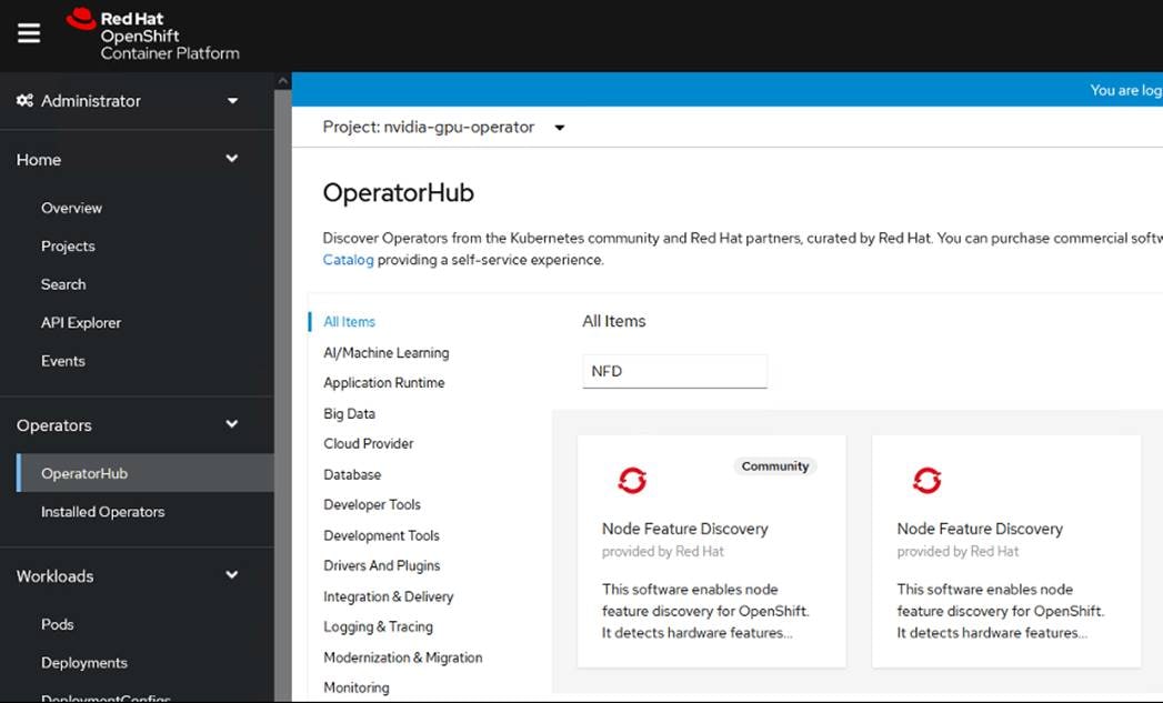
Step 5. Click Install.
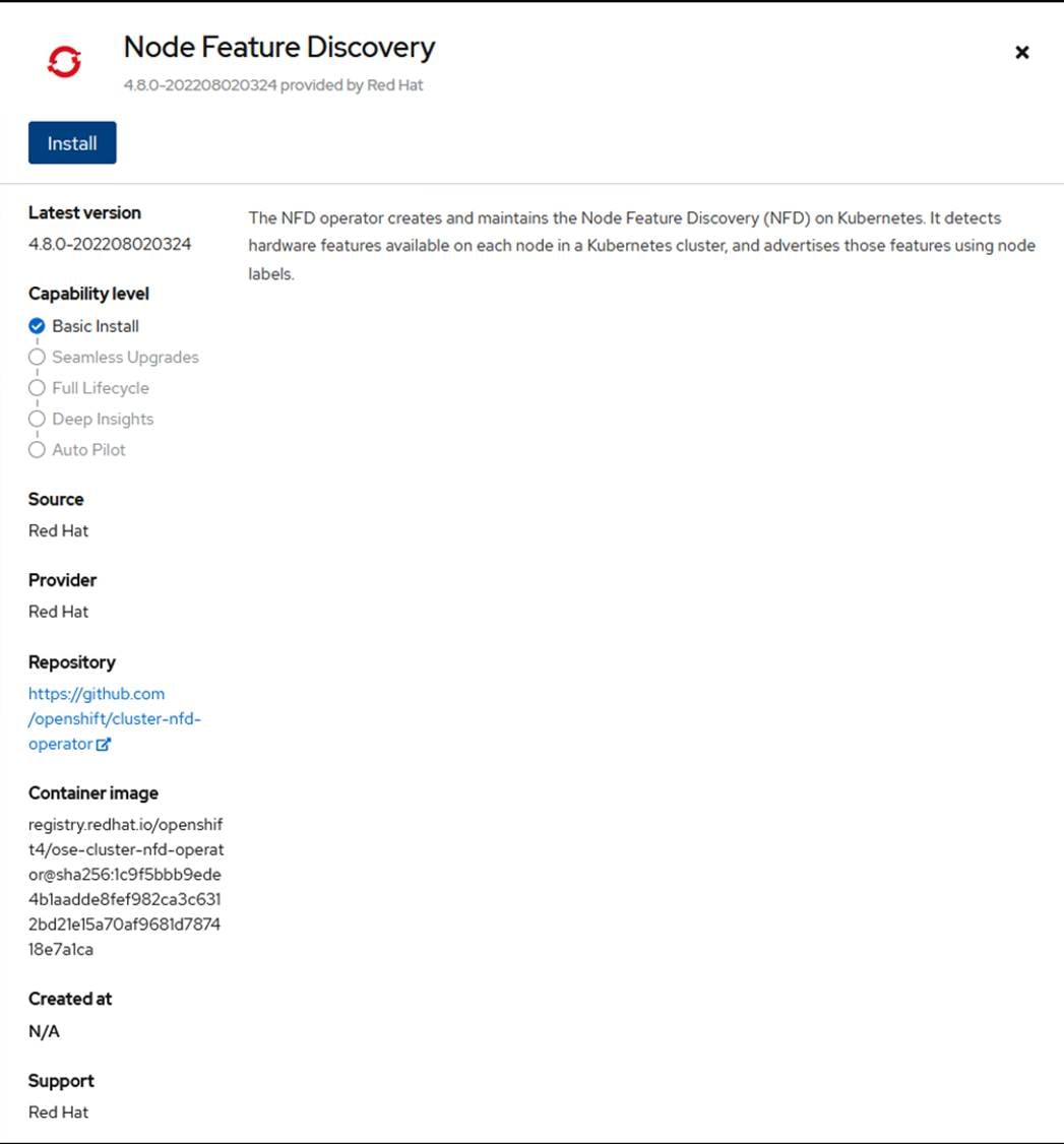
Step 6. Select Update channel, Installation mode and Update approval. Click Install.
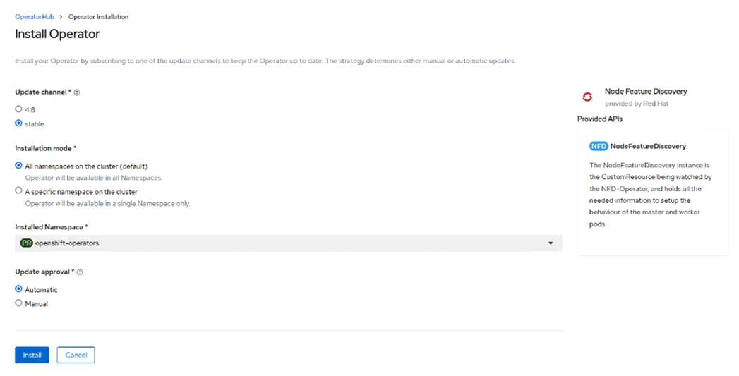
Step 7. After successful installation click View Operator.
Step 8. Verify the Node Feature Discovery Operator is running:
# oc get pods -n openshift-operators
NAME READY STATUS RESTARTS AGE
nfd-controller-manager-57f65794f6-qg9fp 2/2 Running 0 112s
Step 9. When the Node Feature Discovery is installed, create an instance of Node Feature Discovery using the NodeFeatureDiscovery tab.
Step 10. Click Operators > Installed Operators from the side menu.
Step 11. Find the Node Feature Discovery entry.
Step 12. Click NodeFeatureDiscovery under the Provided APIs field.
Step 13. Click Create NodeFeatureDiscovery.
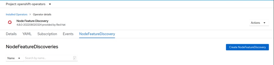
Step 14. Select default values and click Create.
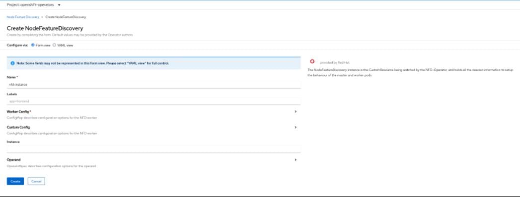
Note: The values pre-populated by the OperatorHub are valid for the GPU Operator.
Step 15. Node Feature Discovery Operator proceeds to label the nodes in the cluster that have GPUs.
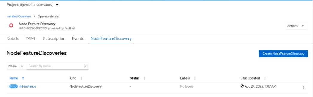
Step 16. Verify that the Node Feature Discovery Operator is functioning correctly.
# oc get pods -n openshift-operators
NAME READY STATUS RESTARTS AGE
nfd-controller-manager-57f65794f6-qg9fp 2/2 Running 0 4m13s
nfd-master-4zmj2 1/1 Running 0 35s
nfd-master-6dxhn 1/1 Running 0 35s
nfd-master-86nw2 1/1 Running 0 35s
nfd-worker-8ltjh 1/1 Running 0 35s
nfd-worker-djlr5 1/1 Running 0 35s
nfd-worker-ks5pf 1/1 Running 0 35s
nfd-worker-r8f62 1/1 Running 0 35s
nfd-worker-wjtj2 1/1 Running 0 35s
Step 17. The Node Feature Discovery Operator uses vendor PCI IDs to identify hardware in a node. NVIDIA uses the PCI ID 10de. Use the OpenShift Container Platform web console or the CLI to verify that the Node Feature Discovery Operator is functioning correctly.
Step 18. In the OpenShift Container Platform web console, click Compute > Nodes > Details tab from the side menu. Select a worker node that contains GPU. Under Node labels verify that the following label is present: “feature.node.kubernetes.io/pci-10de.present=true”
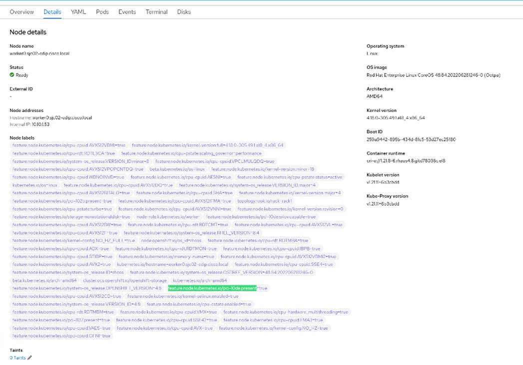
Note: 0x10de is the PCI vendor ID that is assigned to NVIDIA.
Step 19. Verify the GPU device (pci-10de) is discovered on the GPU node:
# oc describe node | egrep 'Roles|pci' | grep -v master
Roles: worker
feature.node.kubernetes.io/pci-102b.present=true
feature.node.kubernetes.io/pci-10de.present=true
feature.node.kubernetes.io/pci-10de.sriov.capable=true
feature.node.kubernetes.io/pci-1137.present=true
Roles: worker
feature.node.kubernetes.io/pci-102b.present=true
feature.node.kubernetes.io/pci-10de.present=true
feature.node.kubernetes.io/pci-10de.sriov.capable=true
feature.node.kubernetes.io/pci-1137.present=true
Roles: worker
feature.node.kubernetes.io/pci-102b.present=true
feature.node.kubernetes.io/pci-1137.present=true
Roles: worker
feature.node.kubernetes.io/pci-102b.present=true
feature.node.kubernetes.io/pci-1137.present=true
Roles: worker
feature.node.kubernetes.io/pci-102b.present=true
feature.node.kubernetes.io/pci-1137.present=true
# oc describe node | egrep 'Roles|pci' | grep -v master | grep pci-10de
feature.node.kubernetes.io/pci-10de.present=true
feature.node.kubernetes.io/pci-10de.sriov.capable=true
feature.node.kubernetes.io/pci-10de.present=true
feature.node.kubernetes.io/pci-10de.sriov.capable=true
Procedure 2. Install NVIDIA GPU Operator using the web console for RHOCP
Step 1. In the OpenShift Container Platform web console from the side menu, navigate to Operators > OperatorHub. Search for “NVIDIA.”
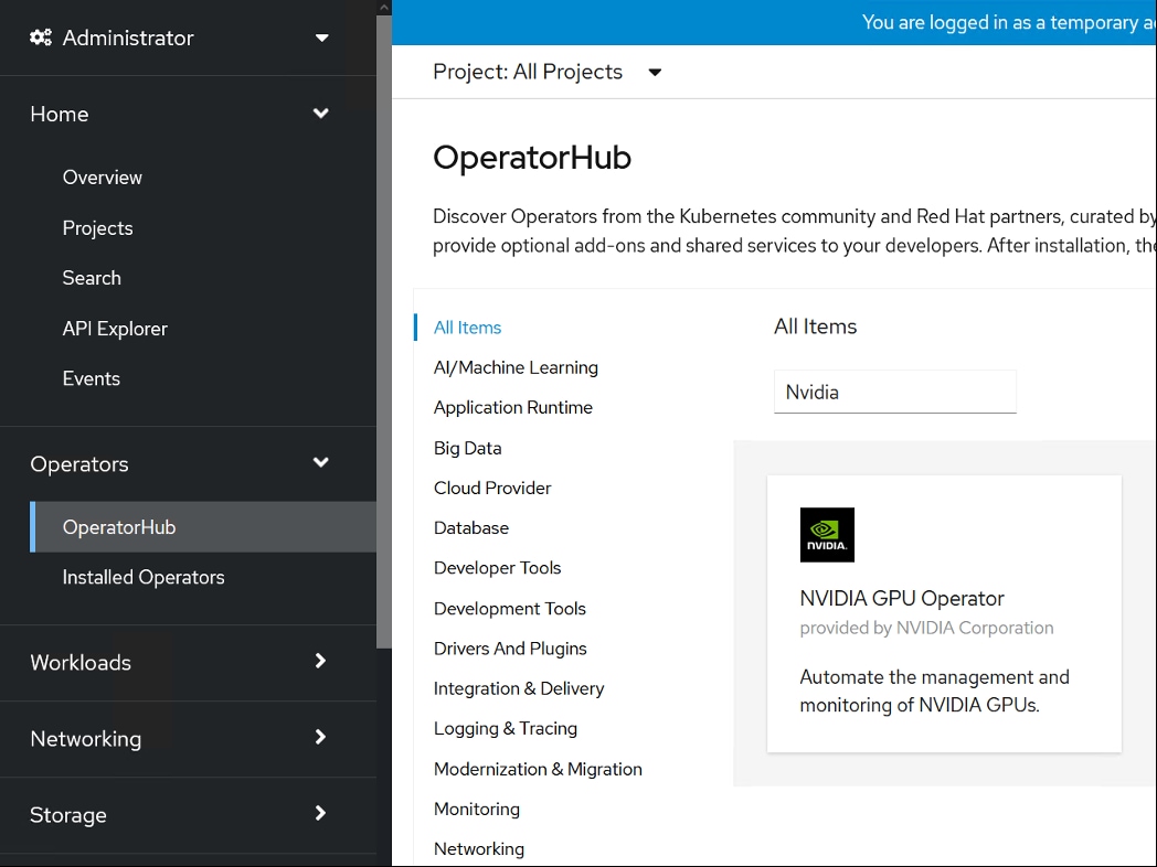
Step 2. Select NVIDIA GPU Operator. Click Install.
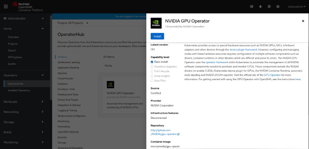
Step 3. Select update channel, Installation mode, default operator recommended namespace and update approval. Click Install.
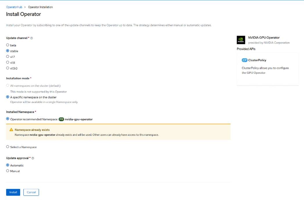
Step 4. After successful installation of NVIDIA GPU Operator, click View Operator.
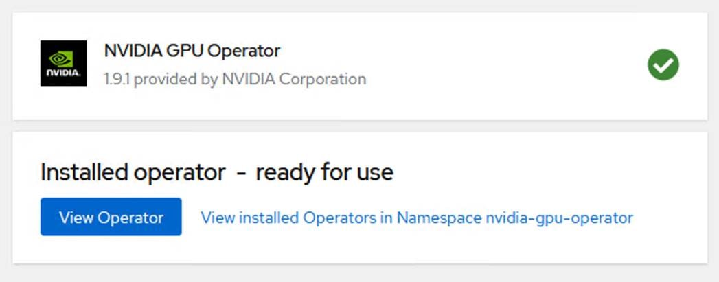
Step 5. Go to ClusterPolicy tab and select CreateClusterPolicy.
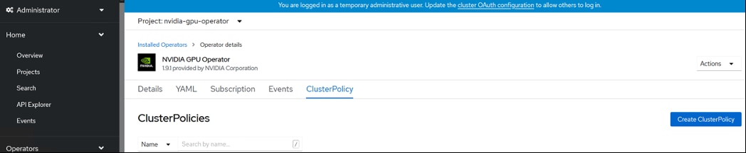
Step 6. Default name “gpu-cluster-policy” is assigned to ClusterPolicy creation. The default settings provided during the Create ClusterPolicy task are sufficient, but they can be customized. Click Create.
Note: We selected the provided default setting for Create ClusterPolicy.
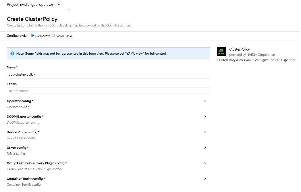
Step 7. Verify the successful installation of the NVIDIA GPU Operator by running command below:
# oc get pods,daemonset -n nvidia-gpu-operator
NAME READY STATUS RESTARTS AGE
pod/gpu-feature-discovery-hm44n 1/1 Running 0 5m27s
pod/gpu-feature-discovery-zzg8q 1/1 Running 0 5m27s
pod/gpu-operator-f95d5d7d5-zqczg 1/1 Running 0 10m
pod/nvidia-container-toolkit-daemonset-tg82z 1/1 Running 0 5m27s
pod/nvidia-container-toolkit-daemonset-wq8np 1/1 Running 0 5m27s
pod/nvidia-cuda-validator-27lx7 0/1 Completed 0 2m28s
pod/nvidia-cuda-validator-z2t7s 0/1 Completed 0 2m38s
pod/nvidia-dcgm-2k6ns 1/1 Running 0 5m27s
pod/nvidia-dcgm-6r26t 1/1 Running 0 5m27s
pod/nvidia-dcgm-exporter-bfxqc 1/1 Running 0 5m27s
pod/nvidia-dcgm-exporter-flggk 1/1 Running 0 5m27s
pod/nvidia-device-plugin-daemonset-2lnms 1/1 Running 0 5m27s
pod/nvidia-device-plugin-daemonset-nw5pr 1/1 Running 0 5m27s
pod/nvidia-device-plugin-validator-fvwhf 0/1 Completed 0 2m16s
pod/nvidia-device-plugin-validator-jgk8k 0/1 Completed 0 2m22s
pod/nvidia-driver-daemonset-48.84.202206281246-0-wdn7f 2/2 Running 0 5m27s
pod/nvidia-driver-daemonset-48.84.202206281246-0-wrwt9 2/2 Running 0 5m27s
pod/nvidia-mig-manager-759rw 1/1 Running 0 87s
pod/nvidia-node-status-exporter-72lgr 1/1 Running 0 5m28s
pod/nvidia-node-status-exporter-scxb8 1/1 Running 0 5m28s
pod/nvidia-operator-validator-lmtzr 1/1 Running 0 5m27s
pod/nvidia-operator-validator-sq7f8 1/1 Running 0 5m27s
NAME DESIRED CURRENT READY UP-TO-DATE AVAILABLE NODE SELECTOR AGE
daemonset.apps/gpu-feature-discovery 2 2 2 2 2 nvidia.com/gpu.deploy.gpu-feature-discovery=true 5m27s
daemonset.apps/nvidia-container-toolkit-daemonset 2 2 2 2 2 nvidia.com/gpu.deploy.container-toolkit=true 5m27s
daemonset.apps/nvidia-dcgm 2 2 2 2 2 nvidia.com/gpu.deploy.dcgm=true 5m27s
daemonset.apps/nvidia-dcgm-exporter 2 2 2 2 2 nvidia.com/gpu.deploy.dcgm-exporter=true 5m27s
daemonset.apps/nvidia-device-plugin-daemonset 2 2 2 2 2 nvidia.com/gpu.deploy.device-plugin=true 5m27s
daemonset.apps/nvidia-driver-daemonset-48.84.202206281246-0 2 2 2 2 2 feature.node.kubernetes.io/system-os_release.OSTREE_VERSION=48.84.202206281246-0,nvidia.com/gpu.deploy.driver=true 5m27s
daemonset.apps/nvidia-mig-manager 1 1 1 1 1 nvidia.com/gpu.deploy.mig-manager=true 5m27s
daemonset.apps/nvidia-node-status-exporter 2 2 2 2 2 nvidia.com/gpu.deploy.node-status-exporter=true 5m28s
daemonset.apps/nvidia-operator-validator 2 2 2 2 2 nvidia.com/gpu.deploy.operator-validator=true 5m27s
# oc get pod -owide -lopenshift.driver-toolkit=true -n nvidia-gpu-operator
NAME READY STATUS RESTARTS AGE IP NODE NOMINATED NODE READINESS GATES
nvidia-driver-daemonset-48.84.202206281246-0-wdn7f 2/2 Running 0 14d 10.254.7.51 worker1.sjc02-cdip.cisco.local <none> <none>
nvidia-driver-daemonset-48.84.202206281246-0-wrwt9 2/2 Running 0 14d 10.254.3.205 worker0.sjc02-cdip.cisco.local <none> <none>
# oc get nodes -o=custom-columns='Node:metadata.name,GPUs:status.capacity.nvidia\.com/gpu'
Node GPUs
master0.sjc02-cdip.cisco.local <none>
master1.sjc02-cdip.cisco.local <none>
master2.sjc02-cdip.cisco.local <none>
worker0.sjc02-cdip.cisco.local 4
worker1.sjc02-cdip.cisco.local 2
worker2.sjc02-cdip.cisco.local <none>
worker3.sjc02-cdip.cisco.local <none>
worker4.sjc02-cdip.cisco.local <none>
# oc exec -it nvidia-driver-daemonset-48.84.202206281246-0-wdn7f -n nvidia-gpu-operator -- nvidia-smi
Defaulting container name to nvidia-driver-ctr.
Use 'oc describe pod/nvidia-driver-daemonset-48.84.202206281246-0-wdn7f -n nvidia-gpu-operator' to see all of the containers in this pod.
Wed Sep 7 19:54:38 2022
+-----------------------------------------------------------------------------+
| NVIDIA-SMI 470.82.01 Driver Version: 470.82.01 CUDA Version: 11.4 |
|-------------------------------+----------------------+----------------------+
| GPU Name Persistence-M| Bus-Id Disp.A | Volatile Uncorr. ECC |
| Fan Temp Perf Pwr:Usage/Cap| Memory-Usage | GPU-Util Compute M. |
| | | MIG M. |
|===============================+======================+======================|
| 0 NVIDIA A100-PCI... On | 00000000:31:00.0 Off | 0 |
| N/A 24C P0 32W / 250W | 0MiB / 40536MiB | 0% Default |
| | | Disabled |
+-------------------------------+----------------------+----------------------+
| 1 NVIDIA A100-PCI... On | 00000000:98:00.0 Off | 0 |
| N/A 24C P0 35W / 250W | 0MiB / 40536MiB | 0% Default |
| | | Disabled |
+-------------------------------+----------------------+----------------------+
+-----------------------------------------------------------------------------+
| Processes: |
| GPU GI CI PID Type Process name GPU Memory |
| ID ID Usage |
|=============================================================================|
| No running processes found |
+-----------------------------------------------------------------------------+
Note: To enable Multi-Instance GPU (MIG) in an RHOCP cluster, follow: https://docs.nvidia.com/datacenter/cloud-native/gpu-operator/openshift/mig-ocp.html
Note: GPU Operator dashboard requires RHOCP v4.10 and higher. https://docs.nvidia.com/datacenter/cloud-native/gpu-operator/openshift/enable-gpu-op-dashboard.html
Note: For airgapped or disconnected environment, follow: https://docs.nvidia.com/datacenter/cloud-native/gpu-operator/openshift/mirror-gpu-ocp-disconnected.html to install GPU Operator.
GPU Node Setup with Cloudera Machine Learning
In Kubernetes, you can taint nodes to affect how the node is scheduled. You can ensure that nodes that have a GPU are reserved exclusively for CML workloads that require a GPU.
To reserve a GPU node, assign a taint to the node.
For OpenShift deployed Cloudera Machine Learning configuration, specify the node taint “nvidia.com/gpu: true:NoSchedule” for any nodes that host GPUs and are required to be used only for GPU workloads.
Procedure 1. Provision a Workspace for CML
Step 1. In Cloudera Private Cloud Management console click Machine Learning.
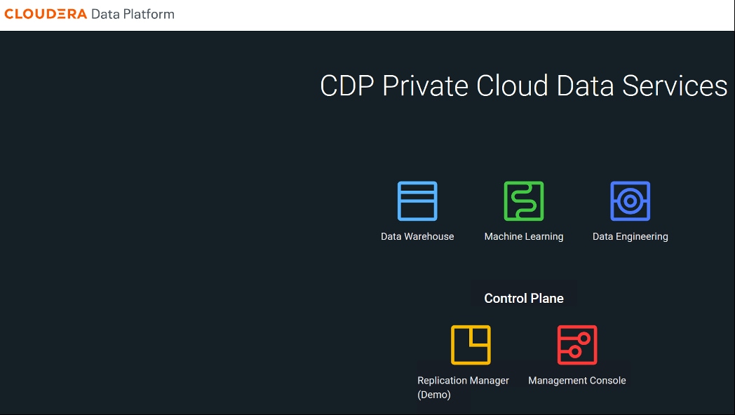
Step 2. Click Provision Workspace.
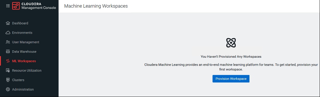
Step 3. Specify the following:
a. Specify the Workspace Name.
b. Select Environment from the drop-down list. This drop-down list displays the registered environment.
c. Specify the Namespace. This is reflected as a Project in Red Hat OpenShift environment.
d. Select Internal or External NFS Server. Internal Kubernetes embedded NFS is recommended. However, already existing NFS environment can also be utilized as long as it is reachable from ML Workspace.
e. Select required check boxes for Production Machine Learning and Other Settings.
f. Click Provision Workspace.
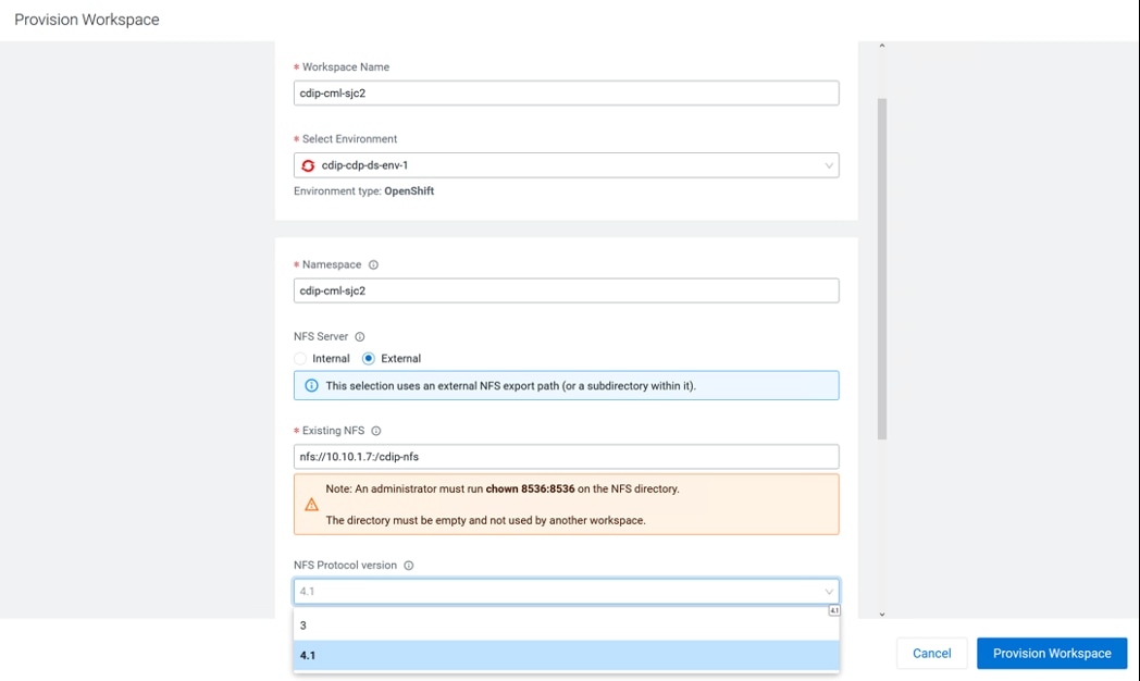
Note: External NFS is recommended deployment for CML. If external NFS is used, the NFS directory and assumed permissions must be those of the cdsw user. For details, https://docs.cloudera.com/machine-learning/1.4.0/private-cloud-requirements/topics/ml-pvc-external-nfs-server.html
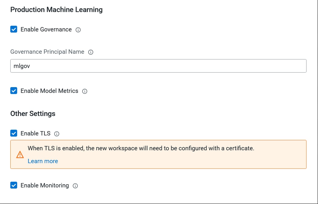
This will start installing workspace. Wait for Status to become “Ready.”
After the successful provisioning of workspace, status reports as “Ready.”
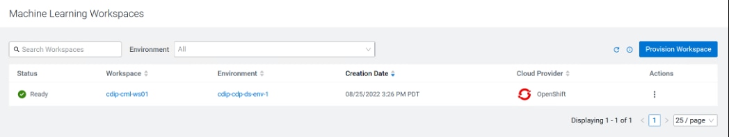
Step 4. Click Workspace to launch the ML Workspace. Click New Project to start a new project in this ML workspace.
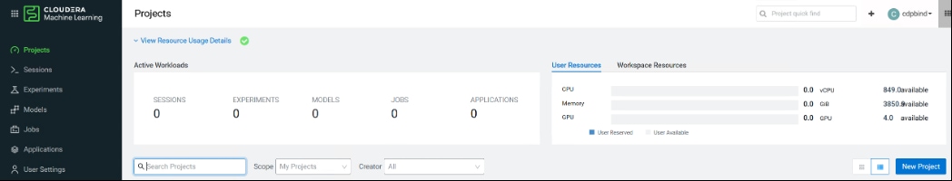
Step 5. Provide Project Name, select Project Visibility and Runtime setup, then click Create Project.
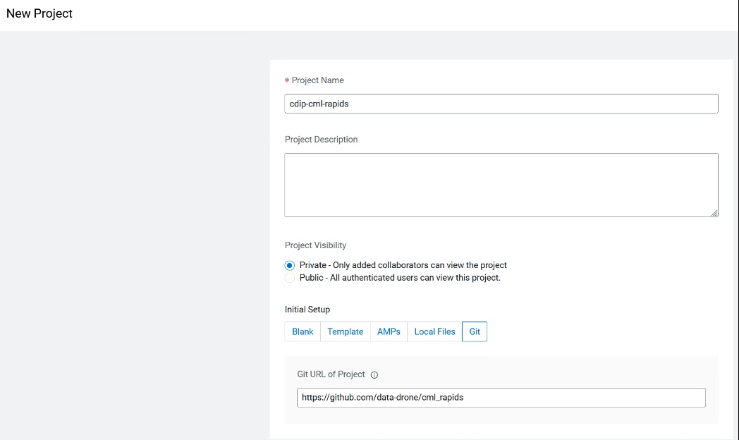
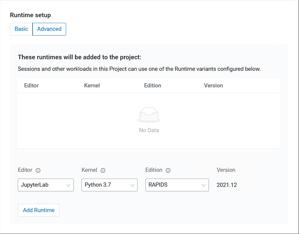
Step 6. Click New Session in the created project.
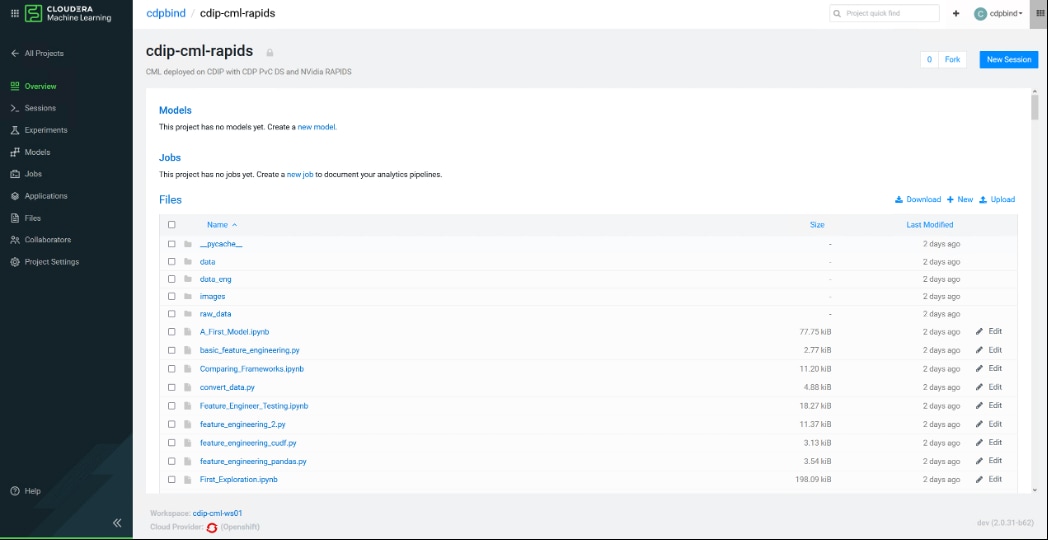
Step 7. To add additional Runtime/Engine; click Project Settings > Click Add Runtime.
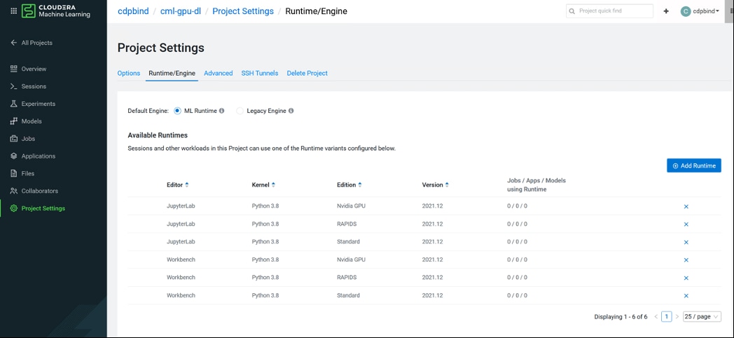
Step 8. This launches the Create Session window. If the session is setup for Hadoop Authentication, you will see “Not authenticated to Hadoop” warning as shown in the figure below. If prompted, enter the details for Hadoop authentication.
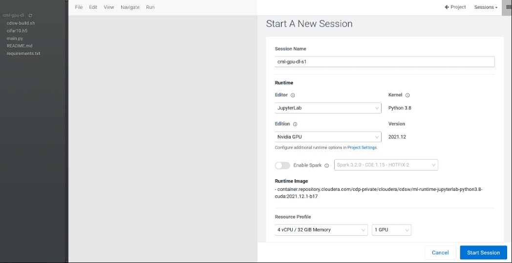
Step 9. Select method to access newly created project.
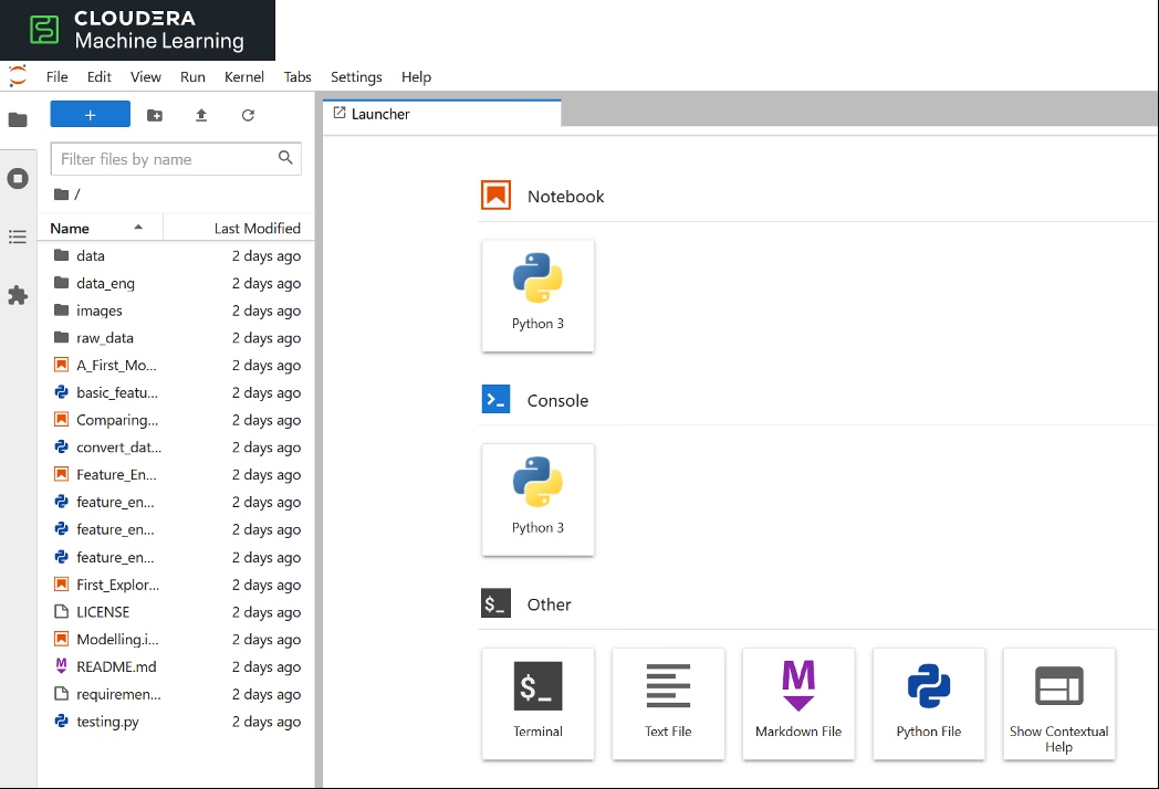
Step 10. Click User Settings > Hadoop Authentication. Without setting up Hadoop Authentication, you will not be able to access HDFS in CML. Provide credentials for Kerberos principal as shown below. In this example, we’re using the same bind user we used for setting up Kerberos in Cloudera Manager. However, a dedicated separate bind user can also be created in Active Directory. Click Authenticate for Kerberos authentication.
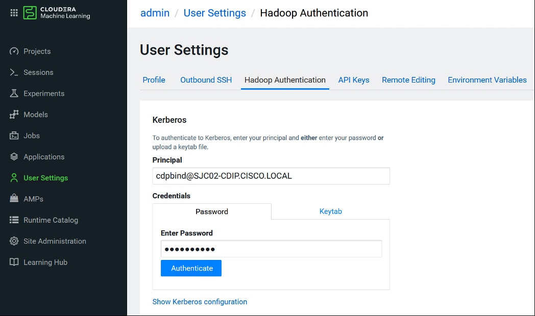
Step 11. If authentication is successful, following output will be displayed.
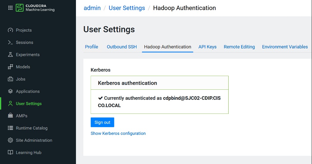
Step 12. Create Resource Profile for Engines. Click Site Administration and the click Runtime/Engine tab. Create Resource Profile with different combination of CPU and memory such as 4 vCPU/8 GiB of Memory.
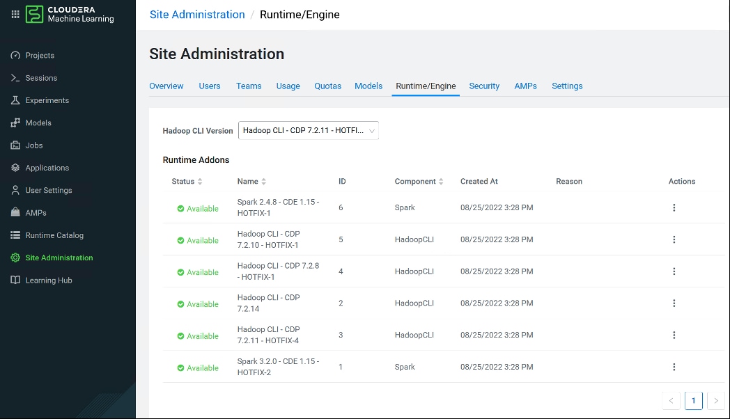
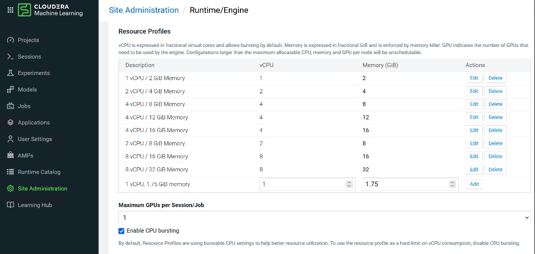
Step 13. Add custom Engine Images by editing description and Repository:Tag field or Environment variables by editing Name and Value.
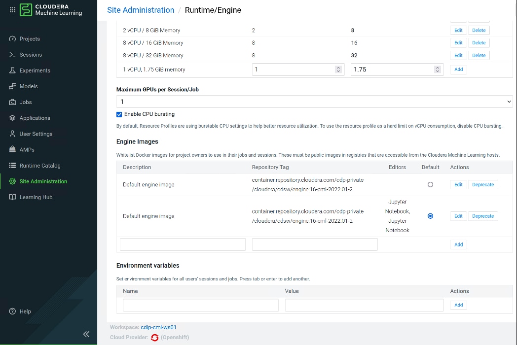
Step 14. Select existing project “cdip-cml-rapids,” click Session to access running session or create new session.
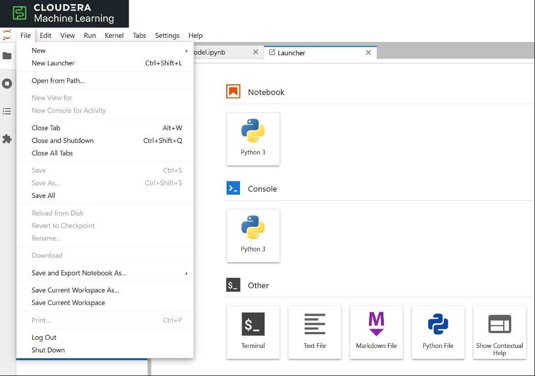
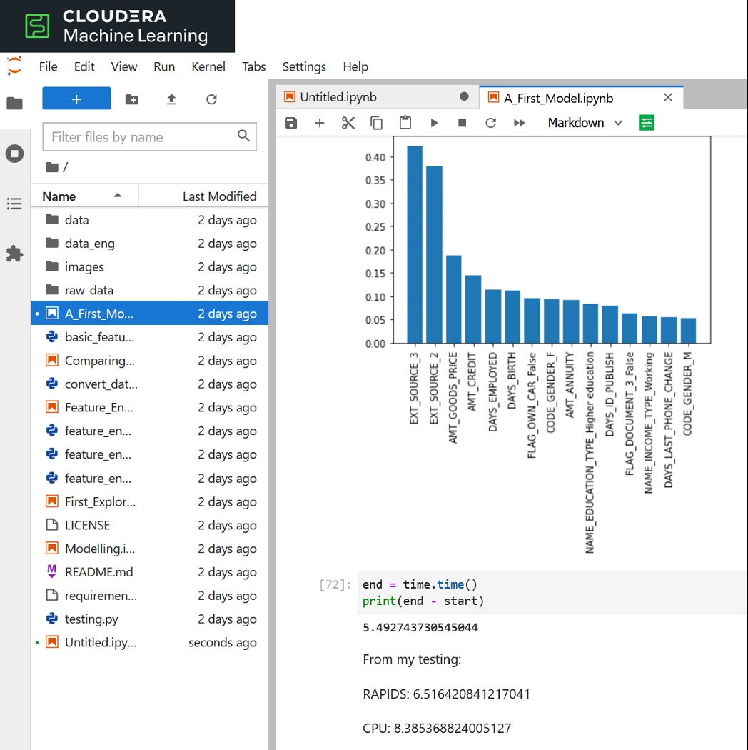
Step 15. The session starts and Jupyter Notebook launches as shown below. Now you’re ready to write ML code in Python in the Notebook. Run the following command to make sure you have access to HDFS:
!hdfs dfs -ls /
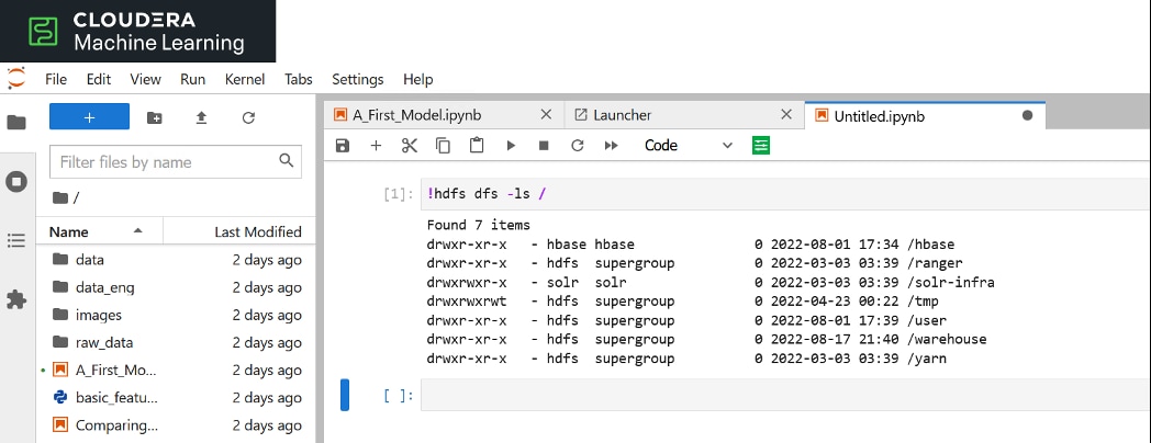
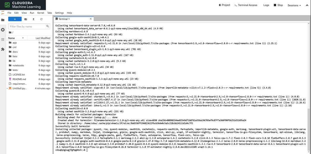
Step 16. Sessions tab shows details on the sessions running.
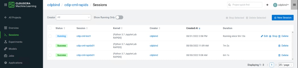
Step 17. To test GPU setup with CML run following commands from workbench session.
! /usr/bin/nvidia-smi
!pip3 install torch==1.4.0
!pip3 install tensorflow-gpu==2.1.0
!pip3 install keras
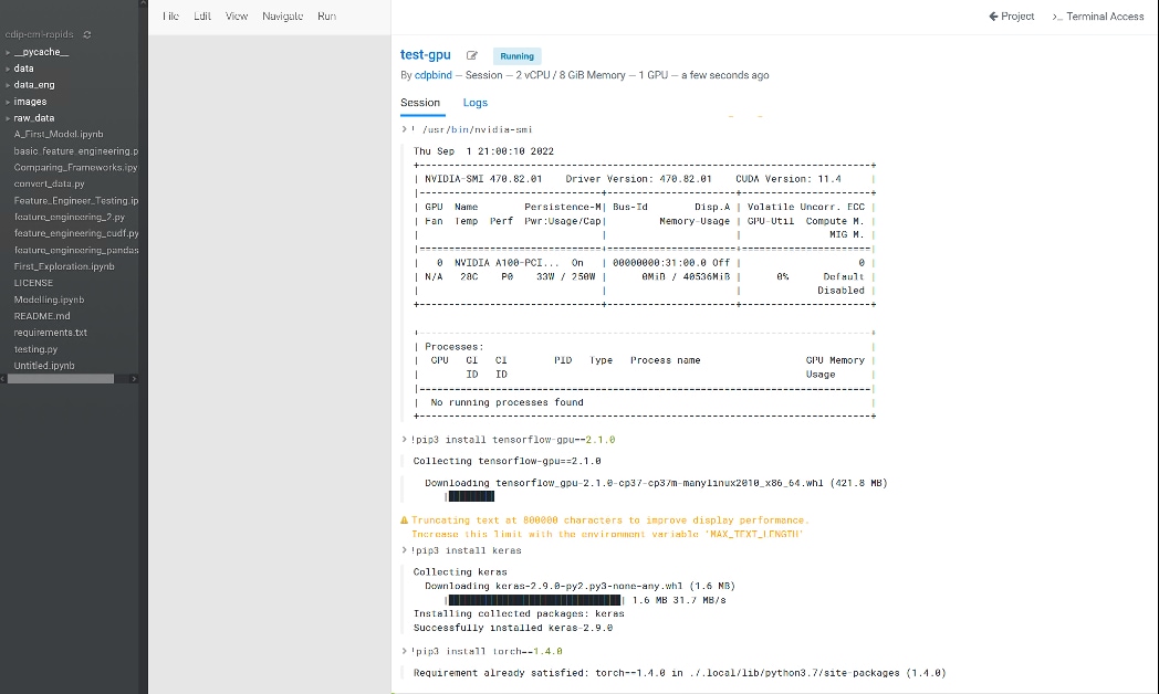
Step 18. Select the AMPs tab to deploy ML prototypes available in CML.
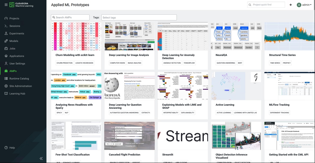
Step 19. Configure and launch project.
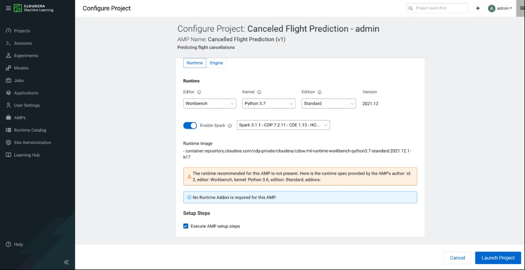
Step 20. Monitor project activity status.
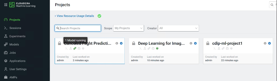
Step 21. Once completed successfully, click on Overview page to check the status of the jobs ran.
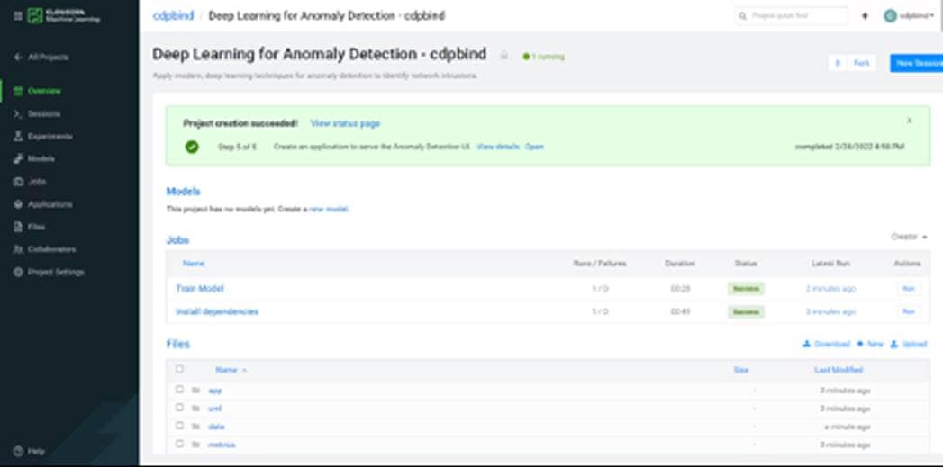
Step 22. Select the train.py from the project folder and run the python script as shown below:
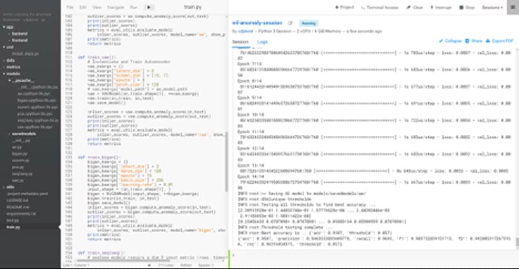
Step 23. Monitor resource utilization from Cloudera Machine Learning console > View Resource Usage Details.
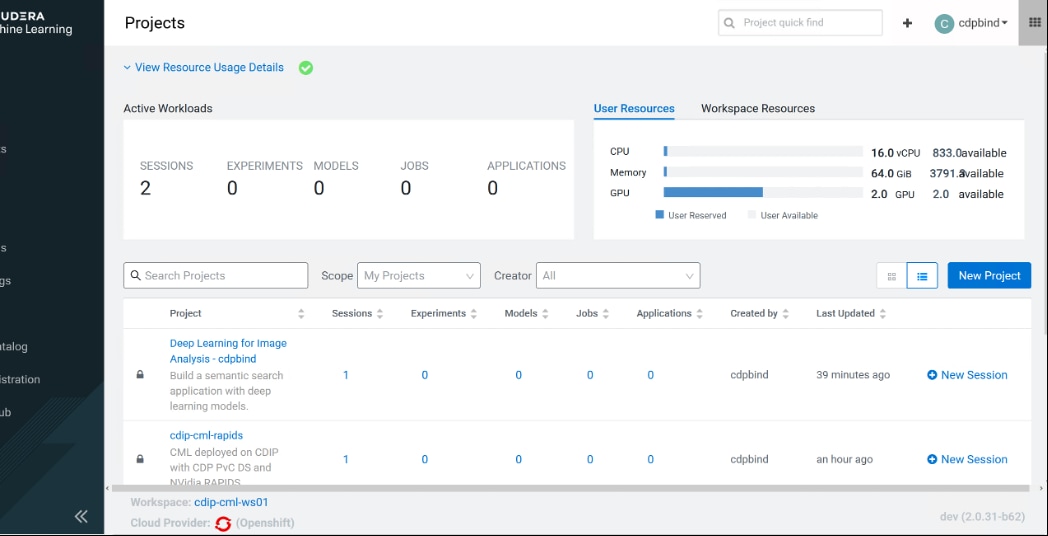
A sample test showing GPU consumption via terminal access in a session running through a project created in CML deployed workspace is shown below reporting single NVIDIA T4 and NVIDIA A100 GPU allocated to each project respectively.
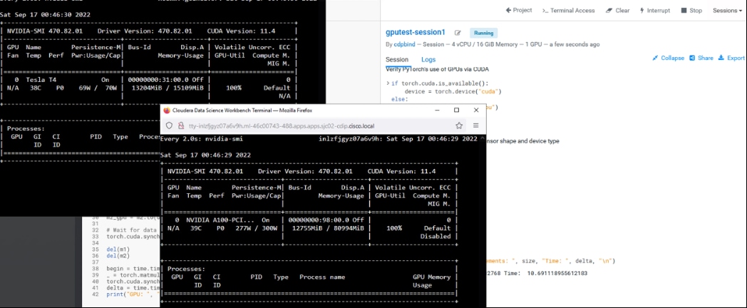
This chapter contains the following:
● Configure Local Volume for CDW
Cloudera Data Warehouse is a CDP Private Cloud service for self-service creation of independent data warehouses and data marts that auto-scale up and down to meet your varying workload demands. The Data Warehouse service provides isolated compute instances for each data warehouse/mart, automatic optimization, and enables you to save costs while meeting SLAs.
Cloudera Data Platform (CDP), Data Warehouse has a consistent framework that secures and provides governance for all of your data and metadata on private clouds or hybrid clouds.
CDW has local storage requirements as listed in Table 5.
Procedure 1. Configure Local Volume for CDW
Step 1. Login to RHOCP worker node, capture the device ID
# oc debug node/worker0.sjc02-cdip.cisco.local
Starting pod/worker0sjc02-cdipciscolocal-debug ...
To use host binaries, run `chroot /host`
Pod IP: 10.10.1.53
If you don't see a command prompt, try pressing enter.
sh-4.4# chroot /host
sh-4.4# ls -l /dev/disk/by-id | grep nvme2n1
lrwxrwxrwx. 1 root root 13 Apr 21 11:42 nvme-UCSC-NVMEHW-H7680_SDM00000CDA7 -> ../../nvme2n1
lrwxrwxrwx. 1 root root 13 Apr 21 11:42 nvme-eui.0000000000000000000cca0b0137c580 -> ../../nvme2n1
sh-4.4# ls -l /dev/disk/by-id | grep nvme3n1
lrwxrwxrwx. 1 root root 13 Apr 21 11:42 nvme-UCSC-NVMEHW-H7680_SDM00000CDF2 -> ../../nvme3n1
lrwxrwxrwx. 1 root root 13 Apr 21 11:42 nvme-eui.0000000000000000000cca0b0137d400 -> ../../nvme3n1
sh-4.4#
Step 2. Obtain the device id of Nvme1n1 of all the worker nodes and complete the following table. Add more Nvme disk based on your storage requirements for CDW.
Table 9. Device IDs for the locally installed NVMe to be added in local volume configuration
| Node |
Device |
DeviceId |
| Worker0 |
Nvme2n1 |
nvme-UCSC-NVMEHW-H7680_SDM00000CDA7 |
| Worker1 |
Nvme2n1 |
nvme-UCSC-NVMEHW-H7680_SDM00000CDF2 |
| Worker2 |
Nvme2n1 |
nvme-UCSC-NVMEHW-H7680_SDM00000CDC6 |
| Worker3 |
Nvme2n1 |
nvme-UCSC-NVMEHW-H7680_SDM00000CDDA |
| Worker4 |
Nvme2n1 |
nvme-UCSC-NVMEHW-H7680_SDM000011971 |
| Worker0 |
Nvme3n1 |
nvme-UCSC-NVMEHW-H7680_SDM00000E095 |
| Worker1 |
Nvme3n1 |
nvme-UCSC-NVMEHW-H7680_SDM00000CDBA |
| Worker2 |
Nvme3n1 |
nvme-UCSC-NVMEHW-H7680_SDM00000CDED |
| Worker3 |
Nvme2n1 |
nvme-UCSC-NVMEHW-H7680_SDM00000CD88 |
| Worker4 |
Nvme2n1 |
nvme-UCSC-NVMEHW-H7680_SDM00000CDDF |
Step 3. Login to OpenShift Web Console.
Step 4. Click Operators>Operator Hub in the left pane of the OpenShift Web Console.
Step 5. In Installed Operators click Local Storage.
Step 6. Click Create Local Volume.
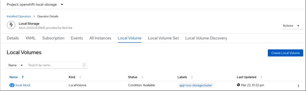
Step 7. Click YAML View and apply the following YAML file:
apiVersion: local.storage.openshift.io/v1
kind: LocalVolume
metadata:
name: local-disks
namespace: openshift-local-storage
labels:
app: ocs-storagecluster
spec:
nodeSelector:
nodeSelectorTerms:
- matchExpressions:
- key: cluster.ocs.openshift.io/openshift-storage
operator: In
values:
- ""
storageClassDevices:
- storageClassName: local-sc
volumeMode: Filesystem
fsType: xfs
devicePaths:
- /dev/disk/by-id/nvme-UCSC-NVMEHW-H7680_SDM00000CDDC # <-- modify this line
- /dev/disk/by-id/nvme-UCSC-NVMEHW-H7680_SDM00000CDBC # <-- modify this line
- /dev/disk/by-id/nvme-UCSC-NVMEHW-H7680_SDM00000CD88 # <-- modify this line
- /dev/disk/by-id/nvme-UCSC-NVMEHW-H7680_SDM00000CDA7 # <-- modify this line
- /dev/disk/by-id/nvme-UCSC-NVMEHW-H7680_SDM00000CDC6 # <-- modify this line
- /dev/disk/by-id/nvme-UCSC-NVMEHW-H7680_SDM000011971 # <-- modify this line
- /dev/disk/by-id/nvme-UCSC-NVMEHW-H7680_SDM00000CDBA # <-- modify this line
- /dev/disk/by-id/nvme-UCSC-NVMEHW-H7680_SDM00000CD96 # <-- modify this line
- /dev/disk/by-id/nvme-UCSC-NVMEHW-H7680_SDM00001196E # <-- modify this line
- /dev/disk/by-id/nvme-UCSC-NVMEHW-H7680_SDM00000CD93 # <-- modify this line
- /dev/disk/by-id/nvme-UCSC-NVMEHW-H7680_SDM00000CDDF # <-- modify this line
- /dev/disk/by-id/nvme-UCSC-NVMEHW-H7680_SDM00000CDF2 # <-- modify this line
- /dev/disk/by-id/nvme-UCSC-NVMEHW-H7680_SDM00000CDDA # <-- modify this line
- /dev/disk/by-id/nvme-UCSC-NVMEHW-H7680_SDM00000E095 # <-- modify this line
- /dev/disk/by-id/nvme-UCSC-NVMEHW-H7680_SDM00000CDED # <-- modify this line
- /dev/disk/by-id/nvme-UCSC-NVMEHW-H7680_SDM00000CD72 # <-- modify this line
Step 8. After modifying the YAML file click Create.
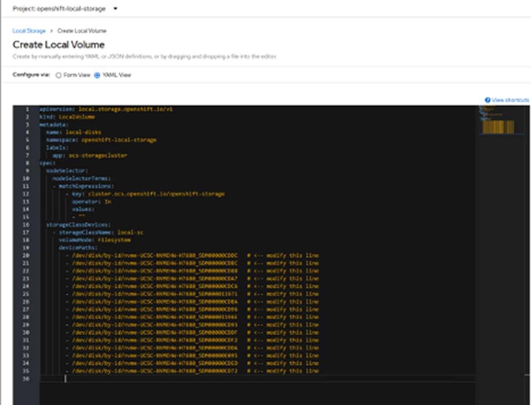
This creates PVs and storage class. Verify the storage class for local-sc as specified in YAML file as shown below.
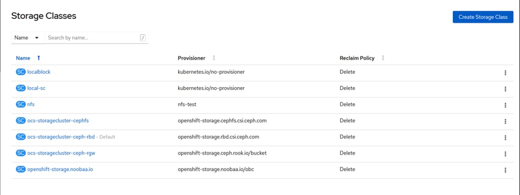
Procedure 2. Create Database Catalog
Step 1. In Cloudera Private Cloud Management console click Data Warehouse.
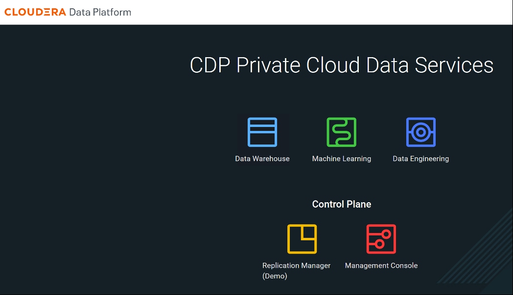
Step 2. In Environments, click ![]() to active the environment.
to active the environment.
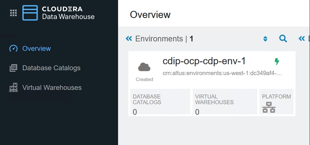
Step 3. Enter required field values.
Step 4. Specify Storage Class Name from Local Storage Operator.
Step 5. Enter Delegation username and password.
Step 6. Enable Low Resource Mode.
Step 7. Click ACTIVATE.
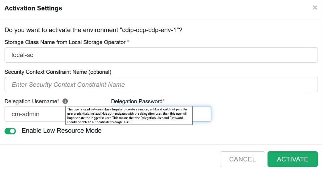
This actives the environment and the database catalog is created.
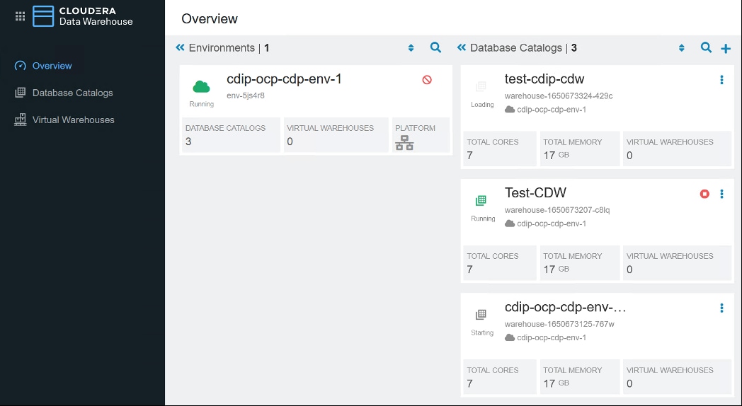
Step 8. Create Virtual Warehouse. Provide warehouse name and select Database Catalog created earlier from the drop-down list. Select Virtual Warehouse Size. Click CREATE.
Note: We selected XSMALL for simplicity.
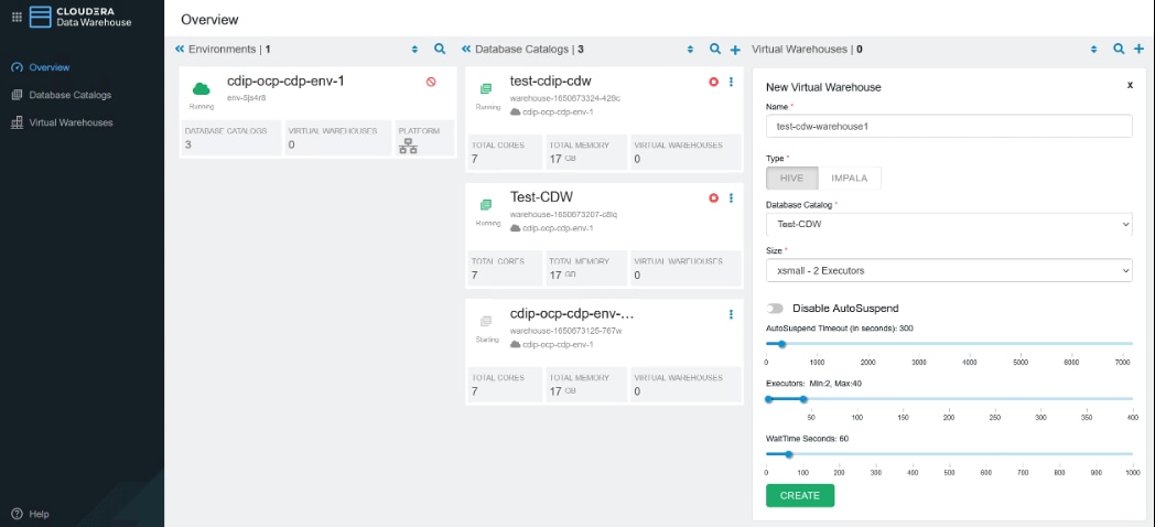
Virtual Warehouses will be created and displayed as shown below:
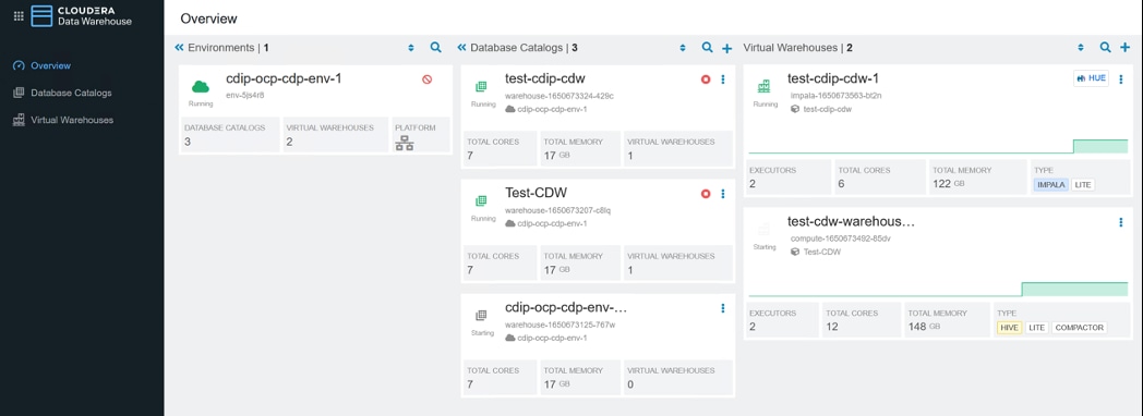
OpenShift console showing warehouse projects created.
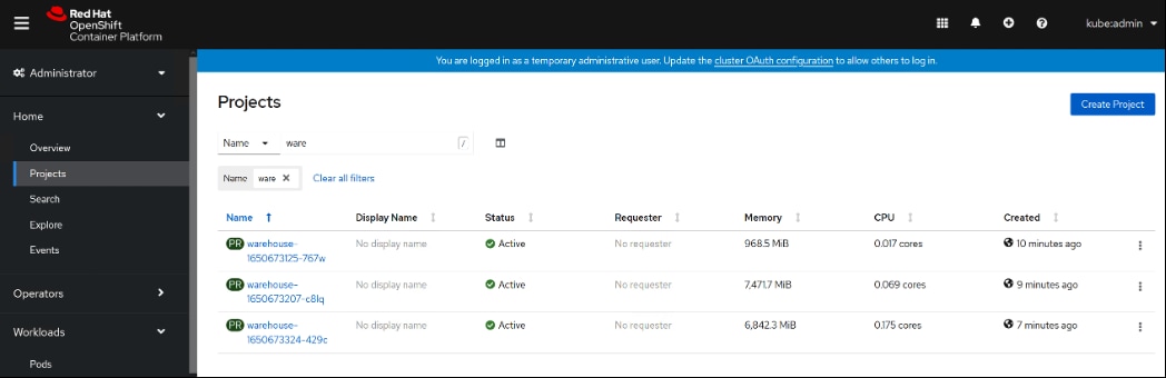
Step 9. Click ![]() . Select Open Hue.
. Select Open Hue.
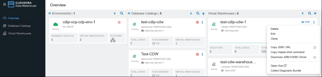
A new tab opens in the Web Browser with Hue interface.
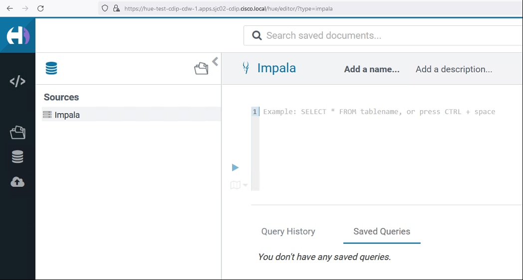
Cloudera Data Engineering (CDE)
This chapter contains the following:
● Cloudera Data Engineering Prerequisites on CDP Private Cloud
● Enable Cloudera Data Engineering (CDE)
● Create Cloudera Data Engineering Virtual Clusters
● Submit Jobs to a CDE Virtual Cluster
Cloudera Data Engineering (CDE) is a cloud-native service purpose-built for enterprise data engineering team to submit Spark jobs to an auto-scaling virtual cluster. Cloudera Data Engineering service allows to create, manage, and schedule Apache Spark jobs without the overhead of creating and maintaining virtual Spark clusters with a range of CPU and memory resources, and the virtual cluster scales up and down as needed to run various Spark workloads.
Cloudera Data Engineering with all-inclusive data engineering toolset that enables orchestration automation with Apache Airflow, advanced pipeline monitoring, visual troubleshooting, and comprehensive management tools to streamline ETL processes across enterprise analytics teams.
Procedure 1. Cloudera Data Engineering Prerequisites on CDP Private Cloud
Note: Before deploying CDE, make sure you have reviewed and complied with the requirements in the installation guide for your environment: https://docs.cloudera.com/data-engineering/1.4.0/prereqs/topics/cde-private-cloud-prereqs.html
Step 1. The CDP Private Cloud Base cluster must have the Apache Ozone service enabled.
Step 2. For CDE Private Cloud running on Red Hat OpenShift Container Platform (RHOCP), you must configure a route admission policy. Configure the OpenShift cluster for running applications in multiple namespaces with the same domain name. Run the following command:
# export KUBECONFIG=</path/to/ocp-kubeconfig>
# oc -n openshift-ingress-operator patch ingresscontroller/default --patch '{"spec":{"routeAdmission":{"namespaceOwnership":"InterNamespaceAllowed"}}}' --type=merge
Procedure 2. Enable Cloudera Data Engineering (CDE)
Step 1. In Cloudera Private Cloud Management console, click on Data Engineering.
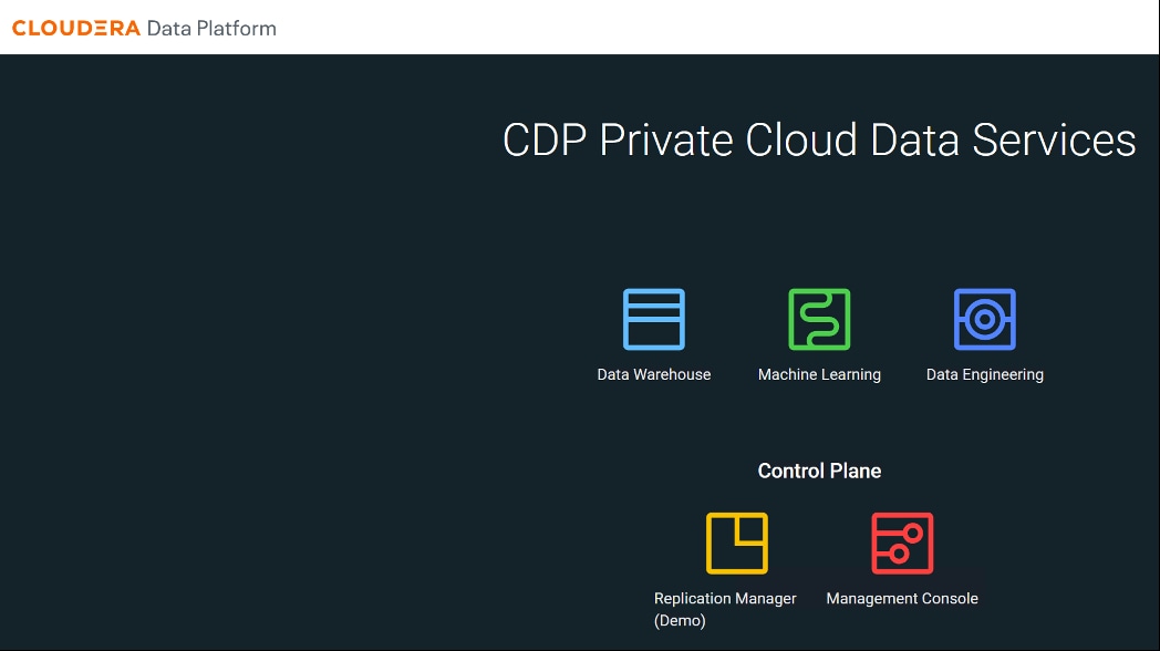
Step 2. Click Enable CDE Service.
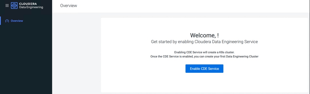
Step 3. Enter Name for the CDE service, from the drop-down list select environment to enable CDE service. Click Enable.
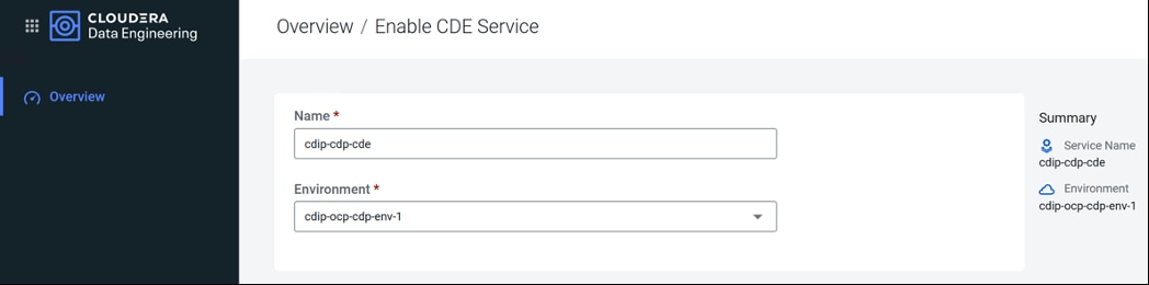
The CDP Private Cloud starts initializing CDE service.
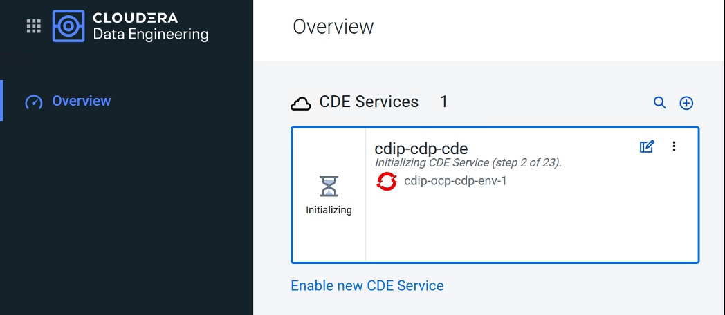
The new namespace “dex-base-xxxxx” gets created in RHOCP.
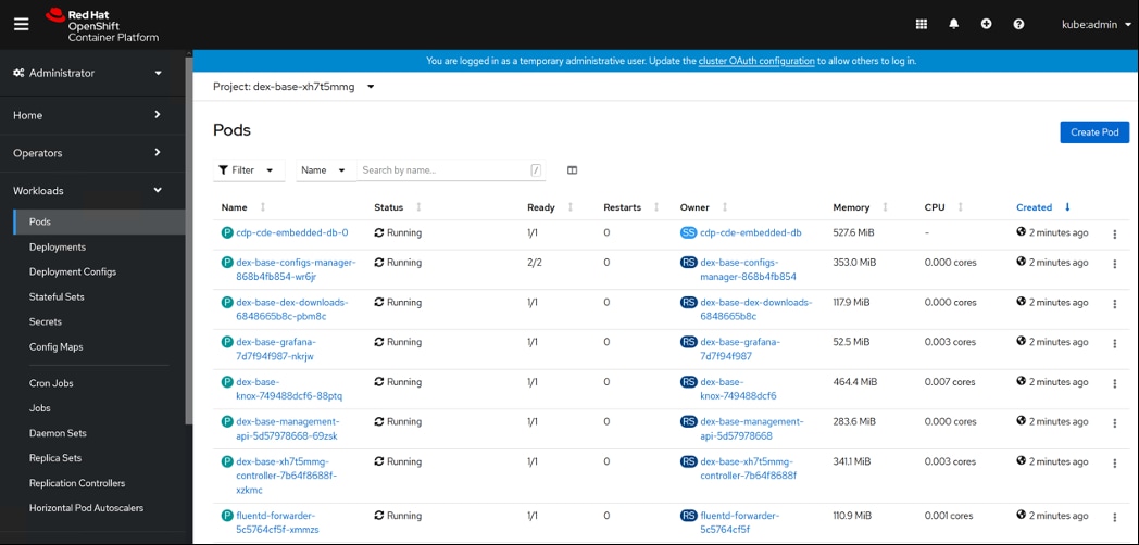
Step 4. When initialization completes, CDE service reports as Enabled. Click the Service Details icon to get more service details.
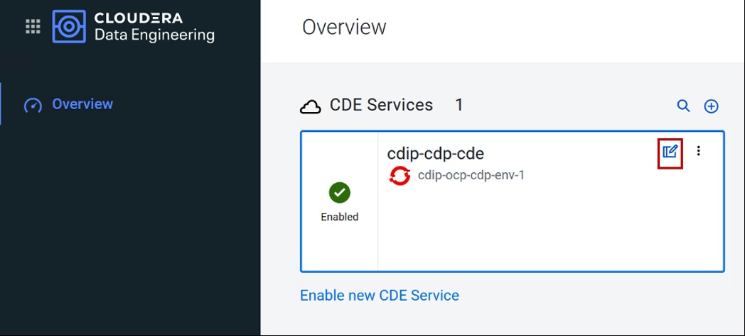
Step 5. Review enabled CDE service details.
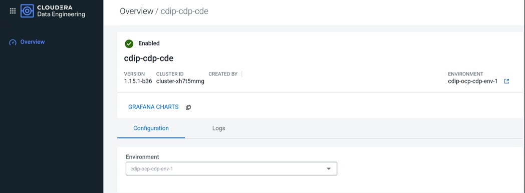
Procedure 3. Create Cloudera Data Engineering Virtual Clusters
Note: In Cloudera Data Engineering (CDE), a virtual cluster is an individual auto-scaling cluster with defined CPU and memory ranges.
Step 1. In Cloudera Private Cloud management console for Data Engineering console, Overview page shows enabled CDE service(s). Select CDE Service. Click Create DE Cluster.
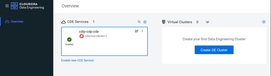
Step 2. Enter name for the Virtual Cluster, from the drop-down list select CDE service, and select Spark version for the virtual cluster. Click Create.
Note: Cluster names must begin with a letter, between 3 and 30 characters (inclusive) and contain only alphanumeric characters and hyphens
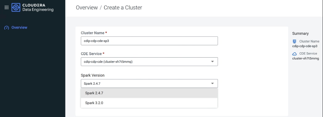
Step 3. Virtual cluster initialization starts; monitor activity by click on Cluster Details icon.
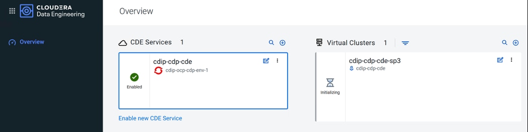
In RHOCP, “dex-app-xxxx” namespace gets created:
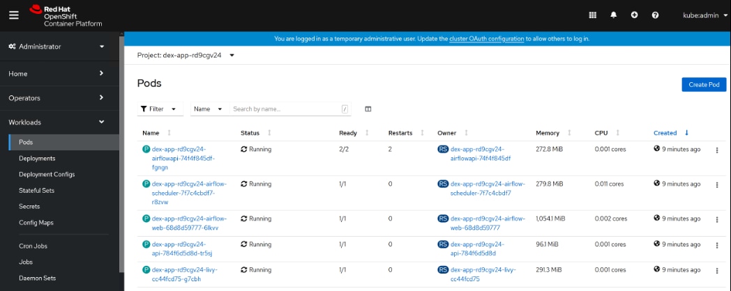
Step 4. Once successful initialization of Virtual Cluster completes, click the cluster details icon.
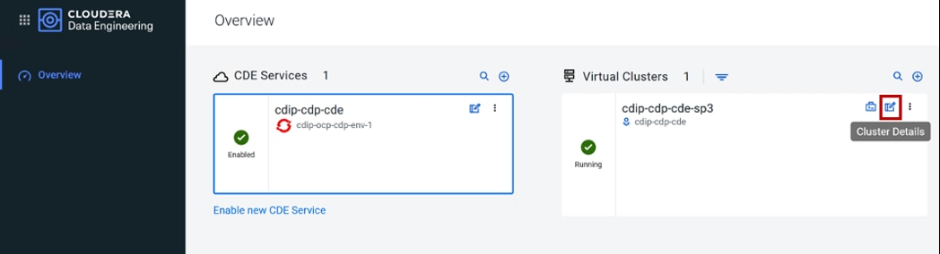
Step 5. Review the CDE Virtual Cluster details.
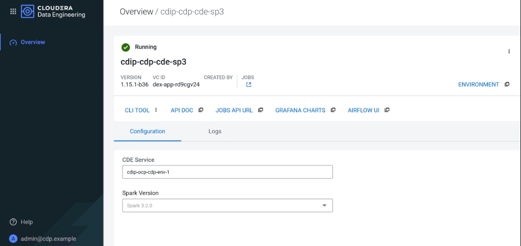
Step 6. After the successful CDE Virtual Cluster creation following the manual steps below for each virtual cluster created in CDP Private Cloud with Red Hat OpenShift Container Platform:
a. Download cdp-cde-utils.sh to your local machine.
# wget https://docs.cloudera.com/data-engineering/1.4.0/cdp-cde-utils.sh
b. Create a directory to store the files, and change to that directory:
# mkdir -p /tmp/cde-1.4.0
# cd /tmp/cde-1.4.0
# chmod +x ~/cdp-cde-utils.sh
c. Copy the “cdp-cde-utils.sh” script and the OpenShift kubeconfig (~/<ocp-install-dir>/auth/kubeconfig) file to one of the HDFS service gateway hosts and install the kubectl utility.
d. Login to Cloudera Manager web interface, go to Clusters > Base Cluster > HDFS > Instances.
e. Select one of the Gateway hosts, log in using the security password that was set, and copy the script to that host.
f. Copy the RHOCP kubeconfig file to the same host.
g. Export the OCP kubeconfig file:
# export KUBECONFIG=~/kubeconfig
h. Install the kubectl utility as highlighted in Kubernetes documentation.
Note: Make sure to install a kubectl version between 1.16 and 1.22 (inclusive). Cloudera recommends installing the version that matches the Kubernetes version installed on the OpenShift cluster.
i. Download kubectl
# curl -LO https://dl.k8s.io/release/v1.21.11/bin/linux/amd64/kubectl
# sudo install -o root -g root -m 0755 kubectl /usr/local/bin/kubectl
# chmod +x /usr/local/bin/kubectl
# kubectl cluster-info
Kubernetes master is running at https://api.sjc02-cdip.cisco.local:6443
To further debug and diagnose cluster problems, use 'kubectl cluster-info dump'.
j. On the cluster host that you copied the script to set the script permissions to be executable:
# chmod +x /path/to/cdp-cde-utils.sh
k. In Cloudera Data Engineering console, select Virtual cluster and click the Cluster details icon.
l. Click JOBS API URL to copy the URL to your clipboard.
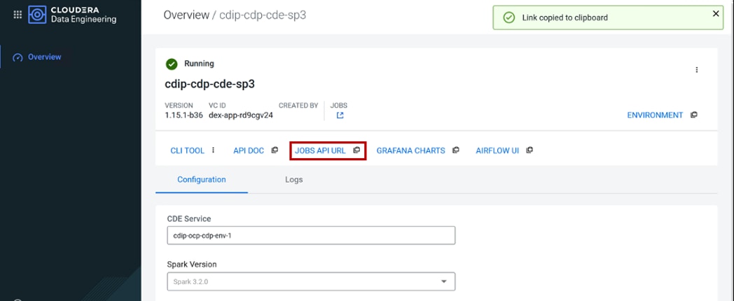
Step 7. Currently, the URL copied to your clipboard begins with http://, not https://. To use the URL, you must manually change this to https://
a. Paste the URL into a text editor to identify the endpoint host.
b. The endpoint host is rd9cgv24.cde-xh7t5mmg.apps.apps.sjc02-cdip.cisco.local.
c. Initialize the virtual cluster using the cdp-cde-utils.sh script on HDFS Gateway host.
Note: You can either generate and use a self-signed certificate or provide a signed certificate and private key.
d. Run following command on HDFS Gateway host to generate a self-signed certificate.
# ./cdp-cde-utils.sh init-virtual-cluster -h <endpoint_host> -a
# export KUBECONFIG=/root/kubeconfig
# ./cdp-cde-utils.sh init-virtual-cluster -h rd9cgv24.cde-xh7t5mmg.apps.apps.sjc02-cdip.cisco.local -a
e. Run following command on HDFS Gateway host to use a signed certificate and private key
Note: Make sure that the certificate is a wildcard certificate for the cluster endpoint. For example, *. rd9cgv24.cde-xh7t5mmg.apps.apps.sjc02-cdip.cisco.local
# ./cdp-cde-utils.sh init-virtual-cluster -h <endpoint_host> -c /path/to/cert -k /path/to/keyfile
# ./cdp-cde-utils.sh init-virtual-cluster -h rd9cgv24.cde-xh7t5mmg.apps.apps.sjc02-cdip.cisco.local -c /tmp/cdp-cde-utils-tmp/certs/ssl.crt -k /tmp/cdp-cde-utils-tmp/certs/ssl.key
Note: Step 7 needs to be repeated for each CDE Virtua Cluster created.
Step 8. On CDE Virtual Cluster, click on briefcase icon to access Jobs page.
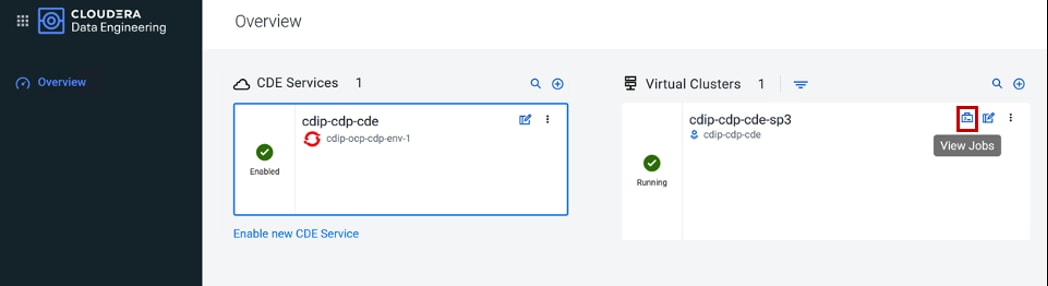
Step 9. Alternatively, the same page can be accessed by clicking JOBS in Cluster Details page.
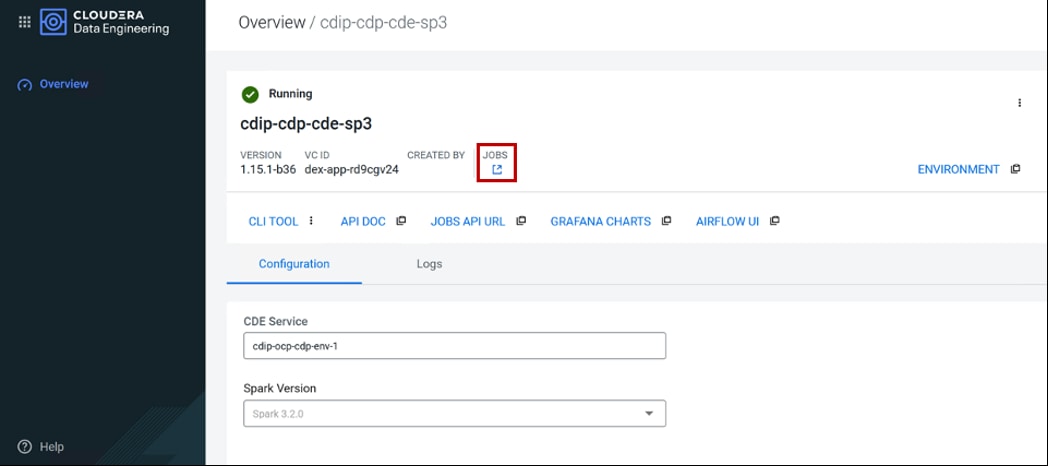
The JOBS page allows to create various job with defined resources on demand or can be scheduled.
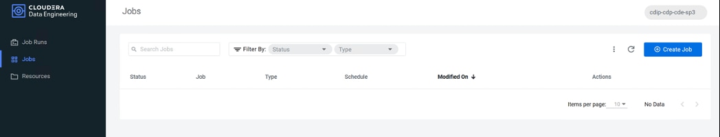
Step 10. Before starting job creation, create a filename containing the user principal and generated a keytab.
Note: If you do not have the ktutil utility, you might need to install the krb5-workstation package. The following example commands assume the user principal is cdpbind@SJC02-CDIP.CISCO.LOCAL (username@Kerberos Security Realm)
# vi cdpbind.principal
cdpbind@SJC02-CDIP.CISCO.LOCAL
# vi cm-admin.principal
cm-admin@SJC02-CDIP.CISCO.LOCAL
# sudo ktutil
addent -password -p cdpbind@SJC02-CDIP.CISCO.LOCAL -k 1 -e aes256-cts
Password for cdpbind@SJC02-CDIP.CISCO.LOCAL:
addent -password -p cdpbind@SJC02-CDIP.CISCO.LOCAL -k 2 -e aes128-cts
Password for cdpbind@SJC02-CDIP.CISCO.LOCAL:
ktutil: addent -password -p cdpbind@SJC02-CDIP.CISCO.LOCAL -k 3 -e rc4-hmac
Password for cdpbind@SJC02-CDIP.CISCO.LOCAL:
ktutil: wkt cdpbind.keytab
ktutil: q
Step 11. Repeat steps 1 – 10 for additional users.
Step 12. Validate the keytab using klist and kinit:
# klist -ekt cdpbind.keytab
Keytab name: FILE:cdpbind.keytab
KVNO Timestamp Principal
---- ------------------- ------------------------------------------------------
3 03/25/2022 12:30:37 cdpbind@SJC02-CDIP.CISCO.LOCAL (arcfour-hmac)
1 03/25/2022 12:32:14 cdpbind@SJC02-CDIP.CISCO.LOCAL (aes256-cts-hmac-sha1-96)
2 03/25/2022 12:32:14 cdpbind@SJC02-CDIP.CISCO.LOCAL (aes128-cts-hmac-sha1-96)
[root@ozone1 ~]# klist -ekt cm-admin.keytab
Keytab name: FILE:cm-admin.keytab
KVNO Timestamp Principal
---- ------------------- ------------------------------------------------------
1 04/12/2022 15:47:47 cdpbind@SJC02-CDIP.CISCO.LOCAL (aes256-cts-hmac-sha1-96)
1 04/12/2022 15:47:47 cm-admin@SJC02-CDIP.CISCO.LOCAL (aes256-cts-hmac-sha1-96)
# kinit -kt cdpbind.keytab cdpbind@SJC02-CDIP.CISCO.LOCAL
# kinit -kt cm-admin.keytab cm-admin@SJC02-CDIP.CISCO.LOCAL
kinit: Pre-authentication failed: No key table entry found for cm-admin@SJC02-CDIP.CISCO.LOCAL while getting initial credentials
Note: Make sure that the keytab is valid before continuing. If the kinit command fails, the user will not be able to run jobs in the virtual cluster. After verifying that the kinit command succeeds, you can destroy the Kerberos ticket by running kdestroy.
Note: Repeat steps 11-12 for all users need to submit jobs to the virtual cluster.
Procedure 4. Submit Jobs to a CDE Virtual Cluster
Step 1. In CDP Private Cloud management console, select Data Engineering. Click on View Jobs icon to open JOBS page. Click on Create Job.
Step 2. Select or enter required fields:
a. Select Spark as job type
b. Enter the job name
c. If the application code is a JAR file, specify the Main Class.
d. Specify arguments if required. Click Add Argument to add multiple command arguments as required.
e. Enter Configurations if needed. Click on Add Configuration button to add multiple configuration parameters as required.
f. Click Advanced Configurations to display more customizations, such as additional files, initial executors, executor range, driver and executor cores and memory.
g. Click Schedule to display scheduling options.
h. You can schedule the application to run periodically using the Basic controls or by specifying a Cron Expression.
i. Click Create and Run to run the job.
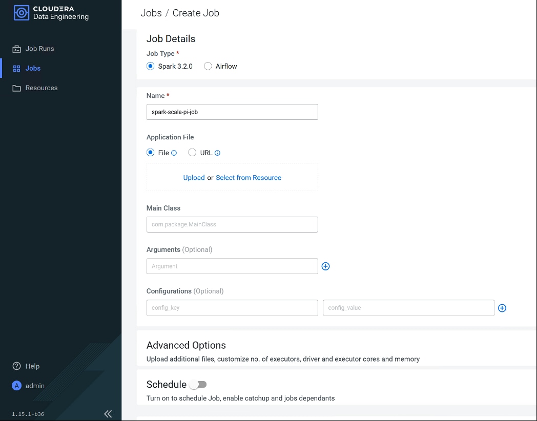
Step 3. Job status can be reviewed in Job Runs page:
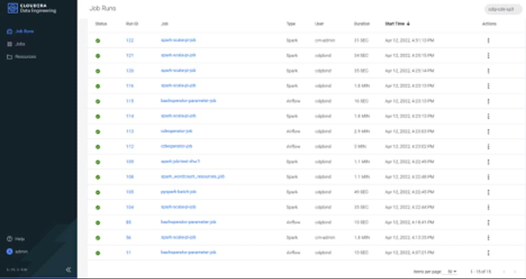
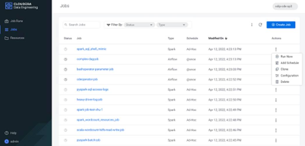
For more information, go to: Creating and Managing Cloudera Data Engineering jobs.
Cisco Data Intelligence Platform (CDIP) offers pre-validated designs both for data lake and private cloud. In these reference designs, Cisco achieved architectural innovation with partners. In addition to that, Cisco published various world record performance benchmarks with TPC (http://www.tpc.org) and proved linear scaling. Cisco published top performance numbers both for traditional map reduce and for Spark which is next generation of compute for crunching big data. And furthermore, CDIP offers centralized management with Cisco Intersight. Cisco Intersight innovation and addition of new features and capabilities is on the highest-gear which will bring lot of exciting innovation with the context of hybrid cloud; and all of it, is fully aligned with Cisco UCS X-series and CDIP, such as solution automation with orchestrator, observability, and monitoring.
In CDIP, Cisco UCS X-series offers excellent platform for container cloud as compute engine for modern apps in the hybrid world. In the coming years, velocity of apps modernization will be tremendous, Cisco UCS X-series is fully aligned with and there will be wave of new technologies coming over such as new compute modules, networking fabric, PCIe fabric, pooled NVMe drives, persistent memory, GPU accelerators, custom ASICs, and so on.
Cisco Data Intelligence Platform powered by Cisco UCS and Cloudera Data Platform enables enterprise-graced analytics and management platform with following key benefits:
● Future proof architecture supporting fast data ingest and management to cater to the variety of analytics workload from edge to AI.
● Ability to auto-scale or cloud burst and suspend according to workload demand.
● Consistent user experience on hybrid cloud and multi-cloud environments.
● Self-service access to integrated, multi-function analytics on centrally managed data eliminating data silos.
About the Authors
Hardik Patel, Technical Marketing Engineer, Cloud and Compute Product Group, Cisco Systems, Inc.
Hardik Patel is a Technical Marketing Engineer in Cisco UCS Product Management and Datacenter Solutions Engineering. He is currently responsible for design and architect of Cisco Data Intelligence Platform based Big Data infrastructure solutions and performance. Hardik holds Master of Science degree in Computer Science with various career-oriented certification in virtualization, network, and Microsoft.
Acknowledgements
For their support and contribution to the design, validation, and creation of this Cisco Validated Design, the authors would like to thank:
● Ali Bajwa, Cloudera
● Marc Chisinevski, Cloudera
This chapter contains the following:
● Appendix A – Bill of Materials
● Appendix B – References Used in this CVD
● Appendix C – Glossary of Terms
● Appendix D –Glossary of Acronyms
● Appendix E – Recommended for You
Appendix A – Bill of Materials
Table 10. Bill of Material for Cisco UCS X210C M6 – RHOCP based CDP PvC DS Cluster
| Part Number |
Description |
Qty |
| UCSX-M6-MLB |
UCSX M6 Modular Server and Chassis MLB |
1 |
| DC-MGT-SAAS |
Cisco Intersight SaaS |
1 |
| DC-MGT-SAAS-EST-C |
Cisco Intersight SaaS - Essentials |
8 |
| SVS-L1DCS-INTER |
CXL1 for INTERSIGHT |
1 |
| DC-MGT-IMCS-1S |
IMC Supervisor - Advanced - 1 Server License |
8 |
| DC-MGT-UCSC-1S |
UCS Central Per Server - 1 Server License |
8 |
| UCSX-9508-U |
UCS 9508 Chassis Configured |
1 |
| CON-OSP-UCSX95U8 |
SNTC-24X7X4OS UCS 9508 Chassis Configured |
1 |
| UCSX-CHASSIS-SW |
Platform SW (Recommended) latest release for X9500 Chassis |
1 |
| UCSX-9508-CAK |
UCS 9508 Chassis Accessory Kit |
1 |
| UCSX-9508-RBLK |
UCS 9508 Chassis Active Cooling Module (FEM slot) |
2 |
| UCSX-9508-ACPEM |
UCS 9508 Chassis Rear AC Power Expansion Module |
2 |
| UCSX-9508-KEY-AC |
UCS 9508 AC PSU Keying Bracket |
1 |
| UCSX-210C-M6 |
UCS 210c M6 Compute Node w/o CPU, Memory, Storage, Mezz |
8 |
| CON-OSP-UCSX210C |
SNTC-24X7X4OS UCS 210c M6 Compute Node w/o CPU, Memory |
8 |
| UCSX-X10C-PT4F |
UCS X10c Compute Pass Through Controller (Front) |
8 |
| UCSX-V4-Q25GML |
UCS VIC 14425 4x25G mLOM for X Compute Node |
8 |
| UCSX-M2-960GB |
Micron 5300 960G SATA M.2 |
16 |
| UCSX-M2-HWRAID |
Cisco Boot optimized M.2 Raid controller |
8 |
| UCSX-TPM-002C |
TPM 2.0, TCG, FIPS140-2, CC EAL4+ Certified, for M6 servers |
8 |
| UCSX-C-SW-LATEST |
Platform SW (Recommended) latest release X-Series Compute Node |
8 |
| UCSX-C-M6-HS-F |
UCS 210c M6 Compute Node Front CPU Heat Sink |
8 |
| UCSX-C-M6-HS-R |
UCS 210c M6 Compute Node Rear CPU Heat Sink |
8 |
| UCS-DIMM-BLK |
UCS DIMM Blanks |
128 |
| UCSX-CPU-I6338 |
Intel 6338 2.0GHz/205W 32C/48MB DDR4 3200MHz |
16 |
| UCSX-MR-X32G2RW |
32GB RDIMM DRx4 3200 (8Gb) |
128 |
| UCSX-NVMEI4-I3200 |
3.2TB 2.5in U.2 Intel P5600 NVMe High Perf High Endurance |
48 |
| UCS-SID-INFR-BD |
Big Data and Analytics Platform (Hadoop/IoT/ITOA/AI/ML) |
8 |
| UCS-SID-WKL-BD |
Big Data and Analytics (Hadoop/IoT/ITOA) |
8 |
| UCSX-I-9108-25G |
UCS 9108-25G IFM for 9508 Chassis |
2 |
| UCSX-PSU-2800AC |
UCS 9508 Chassis 2800V AC Dual Voltage PSU |
6 |
| CAB-US620P-C19-US |
NEMA 6-20 to IEC-C19 13ft US |
6 |
| UCS-FI-6454-U |
UCS Fabric Interconnect 6454 |
1 |
| CON-OSP-SFI6454U |
SNTC-24X7X4OS UCS Fabric Interconnect 6454 |
1 |
| N10-MGT018 |
UCS Manager v4.2 and Intersight Managed Mode v4.2 |
1 |
| UCS-PSU-6332-AC |
UCS 6332/ 6454 Power Supply/100-240VAC |
2 |
| CAB-N5K6A-NA |
Power Cord, 200/240V 6A North America |
2 |
| SFP-25G-AOC3M |
25GBASE Active Optical SFP28 Cable, 3M |
16 |
| UCS-ACC-6332 |
UCS 6332/ 6454 Chassis Accessory Kit |
1 |
| UCS-FAN-6332 |
UCS 6332/ 6454 Fan Module |
4 |
Table 11. Bill of Material for Cisco UCS C240 M6SX – CDP PvC Base Cluster – Ozone Data Node
| Part Number |
Description |
Qty |
| UCS-M6-MLB |
UCS M6 RACK, BLADE MLB |
1 |
| DC-MGT-SAAS |
Cisco Intersight SaaS |
1 |
| DC-MGT-SAAS-EST-C |
Cisco Intersight SaaS - Essentials |
8 |
| SVS-L1DCS-INTER |
CXL1 for INTERSIGHT |
1 |
| DC-MGT-IMCS-1S |
IMC Supervisor - Advanced - 1 Server License |
8 |
| DC-MGT-UCSC-1S |
UCS Central Per Server - 1 Server License |
8 |
| UCSC-C240-M6SX |
UCS C240 M6 Rack w/o CPU, mem, drives, 2U w 24 |
8 |
| CON-OSP-UCSCXC24 |
SNTC-24X7X4OS UCS C240 M6 Rack w/o CPU, mem, drives, 2 |
8 |
| UCSC-ADGPU-240M6 |
C240M6 GPU Air Duct 2USFF/NVMe (for DW/FL only) |
8 |
| UCSC-M-V25-04 |
Cisco UCS VIC 1467 quad port 10/25G SFP28 mLOM |
8 |
| CIMC-LATEST |
IMC SW (Recommended) latest release for C-Series Servers. |
8 |
| UCS-M2-960GB |
960GB SATA M.2 |
16 |
| UCS-M2-HWRAID |
Cisco Boot optimized M.2 Raid controller |
8 |
| UCSX-TPM-002C |
TPM 2.0, TCG, FIPS140-2, CC EAL4+ Certified, for M6 servers |
8 |
| UCSC-RAIL-M6 |
Ball Bearing Rail Kit for C220 & C240 M6 rack servers |
8 |
| UCS-DIMM-BLK |
UCS DIMM Blanks |
128 |
| UCSC-RIS2A-240M6 |
C240 / C245 M6 Riser2A; (x8;x16;x8);StBkt; (CPU2) |
8 |
| UCSC-HSLP-M6 |
Heatsink for 1U/2U LFF/SFF GPU SKU |
16 |
| UCS-SCAP-M6 |
M6 SuperCap |
8 |
| UCSC-M2EXT-240M6 |
C240M6 / C245M6 2U M.2 Extender board |
8 |
| CBL-RSASR3B-240M6 |
C240M6 2U x2 Rear SAS/SATA cable; (Riser3B) |
8 |
| CBL-SDSAS-240M6 |
CBL C240M6X (2U24) MB CPU1(NVMe-A) to PISMO BEACH PLUS |
8 |
| CBL-SCAPSD-C240M6 |
CBL Super Cap for PB+ C240 / C245 M6 |
8 |
| UCS-CPU-I6338 |
Intel 6338 2.0GHz/205W 32C/48MB DDR4 3200MHz |
16 |
| UCS-MR-X32G2RW |
32GB RDIMM DRx4 3200 (8Gb) |
128 |
| UCSC-RIS1A-240M6 |
C240 M6 Riser1A; (x8;x16x, x8); StBkt; (CPU1) |
8 |
| UCSC-RIS3B-240M6 |
C240 M6 Riser 3B; 2xHDD; StBkt; (CPU2) |
8 |
| UCSC-RAID-M6SD |
Cisco M6 12G SAS RAID Controller with 4GB FBWC (28 Drives) |
8 |
| UCS-HD24TB10K4KN |
2.4 TB 12G SAS 10K RPM SFF HDD (4K) |
192 |
| UCS-NVMEI4-I3200 |
3.2TB 2.5in U.2 Intel P5600 NVMe High Perf Medium Endurance |
16 |
| UCSC-PSU1-1600W |
Cisco UCS 1600W AC Power Supply for Rack Server |
16 |
| CAB-N5K6A-NA |
Power Cord, 200/240V 6A North America |
16 |
| RHEL-2S2V-3A |
Red Hat Enterprise Linux (1-2 CPU,1-2 VN); 3-Yr Support Req |
8 |
| CON-ISV1-EL2S2V3A |
ISV 24X7 RHEL Server 2Socket-OR-2Virtual; ANNUAL List Price |
8 |
| UCS-SID-INFR-BD |
Big Data and Analytics Platform (Hadoop/IoT/ITOA/AI/ML) |
8 |
| UCS-SID-WKL-BD |
Big Data and Analytics (Hadoop/IoT/ITOA) |
8 |
Appendix B – References Used in Guide
Cisco Infrastructure Solution for Data Analytics
https://www.cisco.com/c/en/us/solutions/data-center-virtualization/big-data/index.html
Design Zone for Cisco Data Intelligence Platform:
Cloudera Private Cloud Getting Started Guide:
https://docs.cloudera.com/cdp-private-cloud/latest/index.html
CDP Private Cloud Machine Learning Overview:
https://docs.cloudera.com/machine-learning/1.4.0/index.html
CDP Private Cloud Data Engineering Overview:
https://docs.cloudera.com/data-engineering/1.4.0/index.html
CDP Private Cloud Data Warehouse Overview:
https://docs.cloudera.com/data-warehouse/1.4.0/index.html
Appendix C – Glossary of Terms
This glossary addresses some terms used in this document, for the purposes of aiding understanding. This is not a complete list of all multicloud terminology. Some Cisco product links are supplied here also, where considered useful for the purposes of clarity, but this is by no means intended to be a complete list of all applicable Cisco products.
| aaS/XaaS (IT capability provided as a Service) |
Some IT capability, X, provided as a service (XaaS). Some benefits are:
● The provider manages the design, implementation, deployment, upgrades, resiliency, scalability, and overall delivery of the service and the infrastructure that supports it.
● There are very low barriers to entry, so that services can be quickly adopted and dropped in response to business demand, without the penalty of inefficiently utilized CapEx.
● The service charge is an IT OpEx cost (pay-as-you-go), whereas the CapEx and the service infrastructure is the responsibility of the provider.
● Costs are commensurate to usage and hence more easily controlled with respect to business demand and outcomes.
Such services are typically implemented as “microservices,” which are accessed via REST APIs. This architectural style supports composition of service components into systems. Access to and management of aaS assets is via a web GUI and/or APIs, such that Infrastructure-as-code (IaC) techniques can be used for automation, for example, Ansible and Terraform. The provider can be any entity capable of implementing an aaS “cloud-native” architecture. The cloud-native architecture concept is well-documented and supported by open-source software and a rich ecosystem of services such as training and consultancy. The provider can be an internal IT department or any of many third-party companies using and supporting the same open-source platforms. Service access control, integrated with corporate IAM, can be mapped to specific users and business activities, enabling consistent policy controls across services, wherever they are delivered from. |
| Ansible |
An infrastructure automation tool, used to implement processes for instantiating and configuring IT service components, such as VMs on an IaaS platform. Supports the consistent execution of processes defined in YAML “playbooks” at scale, across multiple targets. Because the Ansible artefacts (playbooks) are text-based, they can be stored in a Source Code Management (SCM) system, such as GitHub. This allows for software development like processes to be applied to infrastructure automation, such as, Infrastructure-as-code (see IaC below). |
| AWS (Amazon Web Services) |
Provider of IaaS and PaaS. |
| Azure |
Microsoft IaaS and PaaS. |
| Co-located data center |
“A colocation center (CoLo)…is a type of data center where equipment, space, and bandwidth are available for rental to retail customers. Colocation facilities provide space, power, cooling, and physical security for the server, storage, and networking equipment of other firms and also connect them to a variety of telecommunications and network service providers with a minimum of cost and complexity.” |
| Containers (Docker) |
A (Docker) container is a means to create a package of code for an application and its dependencies, such that the application can run on different platforms which support the Docker environment. In the context of aaS, microservices are typically packaged within Linux containers orchestrated by Kubernetes (K8s). https://www.cisco.com/c/en/us/products/cloud-systems-management/containerplatform/index.html |
| DevOps |
The underlying principle of DevOps is that the application development and operations teams should work closely together, ideally within the context of a toolchain that automates the stages of development, test, deployment, monitoring, and issue handling. DevOps is closely aligned with IaC, continuous integration and deployment (CI/CD), and Agile software development practices. |
| Edge compute |
Edge compute is the idea that it can be more efficient to process data at the edge of a network, close to the endpoints that originate that data, or to provide virtualized access services, such as at the network edge. This could be for reasons related to low latency response, reduction of the amount of unprocessed data being transported, efficiency of resource utilization, and so on. The generic label for this is Multi-access Edge Computing (MEC), or Mobile Edge Computing for mobile networks specifically. From an application experience perspective, it is important to be able to utilize, at the edge, the same operations model, processes, and tools used for any other compute node in the system. |
| IaaS (Infrastructure as-a-Service) |
Infrastructure components provided aaS, located in data centers operated by a provider, typically accessed over the public Internet. IaaS provides a base platform for the deployment of workloads, typically with containers and Kubernetes (K8s). |
| IaC (Infrastructure as-Code) |
Given the ability to automate aaS via APIs, the implementation of the automation is typically via Python code, Ansible playbooks, and similar. These automation artefacts are programming code that define how the services are consumed. As such, they can be subject to the same code management and software development regimes as any other body of code. This means that infrastructure automation can be subject to all of the quality and consistency benefits, CI/CD, traceability, automated testing, compliance checking, and so on, that could be applied to any coding project. |
| IAM (Identity and Access Management) |
IAM is the means to control access to IT resources so that only those explicitly authorized to access given resources can do so. IAM is an essential foundation to a secure multicloud environment. |
| IBM (Cloud) |
IBM IaaS and PaaS. |
| Intersight |
Cisco Intersight™ is a Software-as-a-Service (SaaS) infrastructure lifecycle management platform that delivers simplified configuration, deployment, maintenance, and support. https://www.cisco.com/c/en/us/products/servers-unified-computing/intersight/index.html |
| GCP (Google Cloud Platform) |
Google IaaS and PaaS. |
| Kubernetes (K8s) |
Kubernetes is an open-source system for automating deployment, scaling, and management of containerized applications. |
| Microservices |
A microservices architecture is characterized by processes implementing fine-grained services, typically exposed via REST APIs and which can be composed into systems. The processes are often container-based, and the instantiation of the services often managed with Kubernetes. Microservices managed in this way are intrinsically well suited for deployment into IaaS environments, and as such, are the basis of a cloud native architecture. |
| PaaS (Platform-as-a-Service) |
PaaS is a layer of value-add services, typically for application development, deployment, monitoring, and general lifecycle management. The use of IaC with IaaS and PaaS is very closely associated with DevOps practices. |
| Private on-premises data center |
A data center infrastructure housed within an environment owned by a given enterprise is distinguished from other forms of data center, with the implication that the private data center is more secure, given that access is restricted to those authorized by the enterprise. Thus, circumstances can arise where very sensitive IT assets are only deployed in a private data center, in contrast to using public IaaS. For many intents and purposes, the underlying technology can be identical, allowing for hybrid deployments where some IT assets are privately deployed but also accessible to other assets in public IaaS. IAM, VPNs, firewalls, and similar are key technologies needed to underpin the security of such an arrangement. |
| REST API |
Representational State Transfer (REST) APIs is a generic term for APIs accessed over HTTP(S), typically transporting data encoded in JSON or XML. REST APIs have the advantage that they support distributed systems, communicating over HTTP, which is a well-understood protocol from a security management perspective. REST APIs are another element of a cloud-native applications architecture, alongside microservices. https://en.wikipedia.org/wiki/Representational_state_transfer |
| SaaS (Software-as-a-Service) |
End-user applications provided “aaS” over the public Internet, with the underlying software systems and infrastructure owned and managed by the provider. |
| SAML (Security Assertion Markup Language) |
Used in the context of Single-Sign-On (SSO) for exchanging authentication and authorization data between an identity provider, typically an IAM system, and a service provider (some form of SaaS). The SAML protocol exchanges XML documents that contain security assertions used by the aaS for access control decisions. https://en.wikipedia.org/wiki/Security_Assertion_Markup_Language |
| Terraform |
An open-source IaC software tool for cloud services, based on declarative configuration files. |
Appendix D –Glossary of Acronyms
AAA—Authentication, Authorization, and Accounting
ACP—Access-Control Policy
ACI—Cisco Application Centric Infrastructure
ACK—Acknowledge or Acknowledgement
ACL—Access-Control List
AD—Microsoft Active Directory
AFI—Address Family Identifier
AMP—Cisco Advanced Malware Protection
AP—Access Point
API—Application Programming Interface
APIC— Cisco Application Policy Infrastructure Controller (ACI)
ASA—Cisco Adaptative Security Appliance
ASM—Any-Source Multicast (PIM)
ASR—Aggregation Services Router
Auto-RP—Cisco Automatic Rendezvous Point protocol (multicast)
AVC—Application Visibility and Control
BFD—Bidirectional Forwarding Detection
BGP—Border Gateway Protocol
BMS—Building Management System
BSR—Bootstrap Router (multicast)
BYOD—Bring Your Own Device
CAPWAP—Control and Provisioning of Wireless Access Points Protocol
CDIP – Cisco Data Intelligence Platform
CDP – Cloudera Data Platform
CDP PvC – Cloudera Data Platform Private Cloud
CDP PvC DS – Cloudera Data Platform Private Cloud Data Services
CDW – Cloudera Data Warehouse
CML – Cloudera Machine Learning
CDE – Cloudera Data Engineering
CEF—Cisco Express Forwarding
CMD—Cisco Meta Data
CPU—Central Processing Unit
CSR—Cloud Services Routers
CTA—Cognitive Threat Analytics
CUWN—Cisco Unified Wireless Network
CVD—Cisco Validated Design
CYOD—Choose Your Own Device
DC—Data Center
DHCP—Dynamic Host Configuration Protocol
DM—Dense-Mode (multicast)
DMVPN—Dynamic Multipoint Virtual Private Network
DMZ—Demilitarized Zone (firewall/networking construct)
DNA—Cisco Digital Network Architecture
DNS—Domain Name System
DORA—Discover, Offer, Request, ACK (DHCP Process)
DWDM—Dense Wavelength Division Multiplexing
ECMP—Equal Cost Multi Path
EID—Endpoint Identifier
EIGRP—Enhanced Interior Gateway Routing Protocol
EMI—Electromagnetic Interference
ETR—Egress Tunnel Router (LISP)
EVPN—Ethernet Virtual Private Network (BGP EVPN with VXLAN data plane)
FHR—First-Hop Router (multicast)
FHRP—First-Hop Redundancy Protocol
FMC—Cisco Firepower Management Center
FTD—Cisco Firepower Threat Defense
GBAC—Group-Based Access Control
GbE—Gigabit Ethernet
Gbit/s—Gigabits Per Second (interface/port speed reference)
GRE—Generic Routing Encapsulation
GRT—Global Routing Table
HA—High-Availability
HQ—Headquarters
HSRP—Cisco Hot-Standby Routing Protocol
HTDB—Host-tracking Database (SD-Access control plane node construct)
IBNS—Identity-Based Networking Services (IBNS 2.0 is the current version)
ICMP— Internet Control Message Protocol
IDF—Intermediate Distribution Frame; essentially a wiring closet.
IEEE—Institute of Electrical and Electronics Engineers
IETF—Internet Engineering Task Force
IGP—Interior Gateway Protocol
IID—Instance-ID (LISP)
IOE—Internet of Everything
IoT—Internet of Things
IP—Internet Protocol
IPAM—IP Address Management
IPS—Intrusion Prevention System
IPSec—Internet Protocol Security
ISE—Cisco Identity Services Engine
ISR—Integrated Services Router
IS-IS—Intermediate System to Intermediate System routing protocol
ITR—Ingress Tunnel Router (LISP)
LACP—Link Aggregation Control Protocol
LAG—Link Aggregation Group
LAN—Local Area Network
L2 VNI—Layer 2 Virtual Network Identifier; as used in SD-Access Fabric, a VLAN.
L3 VNI— Layer 3 Virtual Network Identifier; as used in SD-Access Fabric, a VRF.
LHR—Last-Hop Router (multicast)
LISP—Location Identifier Separation Protocol
MAC—Media Access Control Address (OSI Layer 2 Address)
MAN—Metro Area Network
MEC—Multichassis EtherChannel, sometimes referenced as MCEC
MDF—Main Distribution Frame; essentially the central wiring point of the network.
MnT—Monitoring and Troubleshooting Node (Cisco ISE persona)
MOH—Music on Hold
MPLS—Multiprotocol Label Switching
MR—Map-resolver (LISP)
MS—Map-server (LISP)
MSDP—Multicast Source Discovery Protocol (multicast)
MTU—Maximum Transmission Unit
NAC—Network Access Control
NAD—Network Access Device
NAT—Network Address Translation
NBAR—Cisco Network-Based Application Recognition (NBAR2 is the current version).
NFV—Network Functions Virtualization
NSF—Non-Stop Forwarding
OSI—Open Systems Interconnection model
OSPF—Open Shortest Path First routing protocol
OT—Operational Technology
PAgP—Port Aggregation Protocol
PAN—Primary Administration Node (Cisco ISE persona)
PCI DSS—Payment Card Industry Data Security Standard
PD—Powered Devices (PoE)
PETR—Proxy-Egress Tunnel Router (LISP)
PIM—Protocol-Independent Multicast
PITR—Proxy-Ingress Tunnel Router (LISP)
PnP—Plug-n-Play
PoE—Power over Ethernet (Generic term, may also refer to IEEE 802.3af, 15.4W at PSE)
PoE+—Power over Ethernet Plus (IEEE 802.3at, 30W at PSE)
PSE—Power Sourcing Equipment (PoE)
PSN—Policy Service Node (Cisco ISE persona)
pxGrid—Platform Exchange Grid (Cisco ISE persona and publisher/subscriber service)
PxTR—Proxy-Tunnel Router (LISP – device operating as both a PETR and PITR)
QoS—Quality of Service
RADIUS—Remote Authentication Dial-In User Service
REST—Representational State Transfer
RFC—Request for Comments Document (IETF)
RIB—Routing Information Base
RHEL – Red Hat Enterprise Linux
RHOCP – Red Hat OpenShift Container Platform
RLOC—Routing Locator (LISP)
RP—Rendezvous Point (multicast)
RP—Redundancy Port (WLC)
RP—Route Processer
RPF—Reverse Path Forwarding
RR—Route Reflector (BGP)
RTT—Round-Trip Time
SA—Source Active (multicast)
SAFI—Subsequent Address Family Identifiers (BGP)
SD—Software-Defined
SDA—Cisco Software Defined-Access
SDN—Software-Defined Networking
SFP—Small Form-Factor Pluggable (1 GbE transceiver)
SFP+— Small Form-Factor Pluggable (10 GbE transceiver)
SGACL—Security-Group ACL
SGT—Scalable Group Tag, sometimes reference as Security Group Tag
SM—Spare-mode (multicast)
SNMP—Simple Network Management Protocol
SSID—Service Set Identifier (wireless)
SSM—Source-Specific Multicast (PIM)
SSO—Stateful Switchover
STP—Spanning-tree protocol
SVI—Switched Virtual Interface
SVL—Cisco StackWise Virtual
SWIM—Software Image Management
SXP—Scalable Group Tag Exchange Protocol
Syslog—System Logging Protocol
TACACS+—Terminal Access Controller Access-Control System Plus
TCP—Transmission Control Protocol (OSI Layer 4)
UCS— Cisco Unified Computing System
UDP—User Datagram Protocol (OSI Layer 4)
UPoE—Cisco Universal Power Over Ethernet (60W at PSE)
UPoE+— Cisco Universal Power Over Ethernet Plus (90W at PSE)
URL—Uniform Resource Locator
VLAN—Virtual Local Area Network
VM—Virtual Machine
VN—Virtual Network, analogous to a VRF in SD-Access
VNI—Virtual Network Identifier (VXLAN)
vPC—virtual Port Channel (Cisco Nexus)
VPLS—Virtual Private LAN Service
VPN—Virtual Private Network
VPNv4—BGP address family that consists of a Route-Distinguisher (RD) prepended to an IPv4 prefix
VPWS—Virtual Private Wire Service
VRF—Virtual Routing and Forwarding
VSL—Virtual Switch Link (Cisco VSS component)
VSS—Cisco Virtual Switching System
VXLAN—Virtual Extensible LAN
WAN—Wide-Area Network
WLAN—Wireless Local Area Network (generally synonymous with IEEE 802.11-based networks)
WoL—Wake-on-LAN
xTR—Tunnel Router (LISP – device operating as both an ETR and ITR)
Appendix E – Recommended for You
To find out more about Cisco UCS Big Data solutions, go to: https://www.cisco.com/go/bigdata
To find out more about Cisco UCS Big Data validated designs, go to: https://www.cisco.com/go/bigdata_design
To find out more about Cisco Data Intelligence Platform, go to: https://www.cisco.com/c/dam/en/us/products/servers-unified-computing/ucs-c-series-rack-servers/solution-overview-c22-742432.pdf
To find out more about Cisco UCS AI/ML solutions, go to: http://www.cisco.com/go/ai-compute
To find out more about Cisco ACI solutions, go to: http://www.cisco.com/go/aci
To find out more about Cisco validated solutions based on Software Defined Storage, go to: https://www.cisco.com/c/en/us/solutions/data-center-virtualization/software-defined-storage-solutions/index.html
Cloudera Data Platform Private Cloud latest release note, go to: https://docs.cloudera.com/cdp-private-cloud-upgrade/latest/release-guide/topics/cdpdc-release-notes-links.html
Cloudera Data Platform Private Cloud Base Requirements and Supported Versions, go to: https://docs.cloudera.com/cdp-private-cloud-upgrade/latest/release-guide/topics/cdpdc-requirements-supported-versions.html
Cloudera Data Platform Private Cloud Data Services installation on Red Hat OpenShift Container Platform requirements and supported versions, go to: https://docs.cloudera.com/cdp-private-cloud-data-services/1.4.0/installation/topics/cdppvc-installation-overview.html
Cloudera Data Platform Private Cloud Data Services installation on Embedded Container Service requirements and supported versions, go to: https://docs.cloudera.com/cdp-private-cloud-data-services/1.4.0/installation-ecs/topics/cdppvc-installation-ecs-overview.html
For comments and suggestions about this guide and related guides, join the discussion on Cisco Community at https://cs.co/en-cvds.
CVD Program
ALL DESIGNS, SPECIFICATIONS, STATEMENTS, INFORMATION, AND RECOMMENDATIONS (COLLECTIVELY, "DE-SIGNS") IN THIS MANUAL ARE PRESENTED "AS IS," WITH ALL FAULTS. CISCO AND ITS SUPPLIERS DISCLAIM ALL WAR-RANTIES, INCLUDING, WITHOUT LIMITATION, THE WARRANTY OF MERCHANTABILITY, FITNESS FOR A PARTICULAR PURPOSE AND NONINFRINGEMENT OR ARISING FROM A COURSE OF DEALING, USAGE, OR TRADE PRACTICE. IN NO EVENT SHALL CISCO OR ITS SUPPLIERS BE LIABLE FOR ANY INDIRECT, SPECIAL, CONSEQUENTIAL, OR INCIDENTAL DAMAGES, INCLUDING, WITHOUT LIMITATION, LOST PROFITS OR LOSS OR DAMAGE TO DATA ARISING OUT OF THE USE OR INABILITY TO USE THE DESIGNS, EVEN IF CISCO OR ITS SUPPLIERS HAVE BEEN ADVISED OF THE POSSIBILITY OF SUCH DAMAGES.
THE DESIGNS ARE SUBJECT TO CHANGE WITHOUT NOTICE. USERS ARE SOLELY RESPONSIBLE FOR THEIR APPLICA-TION OF THE DESIGNS. THE DESIGNS DO NOT CONSTITUTE THE TECHNICAL OR OTHER PROFESSIONAL ADVICE OF CISCO, ITS SUPPLIERS OR PARTNERS. USERS SHOULD CONSULT THEIR OWN TECHNICAL ADVISORS BEFORE IMPLE-MENTING THE DESIGNS. RESULTS MAY VARY DEPENDING ON FACTORS NOT TESTED BY CISCO.
CCDE, CCENT, Cisco Eos, Cisco Lumin, Cisco Nexus, Cisco StadiumVision, Cisco TelePresence, Cisco WebEx, the Cisco logo, DCE, and Welcome to the Human Network are trademarks; Changing the Way We Work, Live, Play, and Learn and Cisco Store are service marks; and Access Registrar, Aironet, AsyncOS, Bringing the Meeting To You, Catalyst, CCDA, CCDP, CCIE, CCIP, CCNA, CCNP, CCSP, CCVP, Cisco, the Cisco Certified Internetwork Expert logo, Cisco IOS, Cisco Press, Cisco Systems, Cisco Systems Capital, the Cisco Systems logo, Cisco Unified Computing System (Cisco UCS), Cisco UCS B-Series Blade Servers, Cisco UCS C-Series Rack Servers, Cisco UCS S-Series Storage Servers, Cisco UCS Manager, Cisco UCS Management Software, Cisco Unified Fabric, Cisco Application Centric Infrastructure, Cisco Nexus 9000 Series, Cisco Nexus 7000 Series. Cisco Prime Data Center Network Manager, Cisco NX-OS Software, Cis-co MDS Series, Cisco Unity, Collaboration Without Limitation, EtherFast, EtherSwitch, Event Center, Fast Step, Follow Me Browsing, FormShare, GigaDrive, HomeLink, Internet Quotient, IOS, iPhone, iQuick Study, LightStream, Linksys, MediaTone, MeetingPlace, MeetingPlace Chime Sound, MGX, Networkers, Networking Academy, Network Registrar, PCNow, PIX, PowerPanels, ProConnect, ScriptShare, SenderBase, SMARTnet, Spectrum Expert, StackWise, The Fastest Way to Increase Your Internet Quotient, TransPath, WebEx, and the WebEx logo are registered trade-marks of Cisco Systems, Inc. and/or its affiliates in the United States and certain other countries. (LDW_UP1)
All other trademarks mentioned in this document or website are the property of their respective owners. The use of the word partner does not imply a partnership relationship between Cisco and any other company. (0809R)