FlashStack for Microsoft SQL Server 2022 with Cisco UCS X-Series and Pure Storage
Available Languages
Bias-Free Language
The documentation set for this product strives to use bias-free language. For the purposes of this documentation set, bias-free is defined as language that does not imply discrimination based on age, disability, gender, racial identity, ethnic identity, sexual orientation, socioeconomic status, and intersectionality. Exceptions may be present in the documentation due to language that is hardcoded in the user interfaces of the product software, language used based on RFP documentation, or language that is used by a referenced third-party product. Learn more about how Cisco is using Inclusive Language.
- US/Canada 800-553-2447
- Worldwide Support Phone Numbers
- All Tools
 Feedback
 Feedback

In partnership with:
![]()
About the Cisco Validated Design Program
The Cisco Validated Design (CVD) program consists of systems and solutions designed, tested, and documented to facilitate faster, more reliable, and more predictable customer deployments. For more information, go to: http://www.cisco.com/go/designzone.
Ever-changing business needs demand organizations to adopt modern business delivery technologies, tools, platforms, and systems that enable them to develop, test and deploy their applications quickly and continuously. Consistent performance, scalability, high availability, disaster recovery capabilities, and life cycle management are few other challenges organizations are facing today.
This FlashStack® solution is a validated, converged infrastructure developed jointly by Cisco and Pure Storage. The solution offers a predesigned data center architecture that incorporates computing, storage, and network design best practices to reduce IT risk by validating the architecture and helping to ensure compatibility among the components. The solution also addresses IT pain points by providing documented design and deployment guidance and support that can be used in various stages (planning, designing and implementation) of a deployment. The FlashStack solution provides a scalable and agile system with consistent performance, by combining and stitching the best of breed software technologies and modern hardware from both partners.
This document describes a FlashStack reference architecture using the latest hardware and software products providing design and deployment recommendations for hosting Microsoft SQL Server 2022 databases in VMware ESXi virtualized environments. The document provides hardware and software configurations of the components involved, implementation best practices guidance for deploying the solution, results of various performance tests, additional benefits of using latest Intel 4th generation CPUs hardware accelerators, Pure Storage Integrations with vSphere vVols for Snapshots, Clone, and so on, and replication to Azure cloud use case using Pure Cloud Block Storage (CBS) for Disaster Recovery (DR) of the databases.
This chapter contains the following:
● Audience
The current IT industry is experiencing a variety of transformations in datacenter solutions. In recent years, the interest in pre-validated and engineered datacenter solutions have grown tremendously. IT management can no longer have their staff take months trying to test and determine the best practices to set up new infrastructures to support Microsoft SQL Server 2022 deployments. Architectures that combine leading server, storage, management software and data replication tools tested and documented address the IT team’s challenge to implement new solutions quickly and deliver on the promised return on investment (ROI).
The introduction of virtualization technology adds an additional layer of complexity that has significantly impacted the design principles and architectures of these solutions as customers look to consolidate workloads to gain higher system efficiencies from their investment in SQL Server processor core-based database licenses.
Microsoft SQL Server is the most widely installed database management system in the world today and supports many critical applications that impact a company’s bottom line. “Database Sprawl” is one of the challenges that many customers are facing today. Some of the challenges this represents include underutilized servers, incorrect licensing, security concerns, management concerns, huge operational costs, and so on. To overcome these challenges, many customers are moving towards migrating and consolidating databases into robust, flexible, and resilient platforms such as FlashStack. This document describes a FlashStack reference architecture for deploying and consolidating SQL Server 2022 databases.
Hosting SQL Server databases on Pure Storage FlashArray is an extremely popular use case. FlashArray’s Direct Flash Modules (DFMs) offer sub-millisecond latency for your business’s most demanding OLTP workloads. And the Purity Operating Environment brings numerous benefits, including global data-deduplication, encryption-at-rest, and a UI focused on simplicity and efficiency. Purity also offers multiple replication solutions, including snapshots, and near real time asynchronous and synchronous streaming replication, enabling simple and fast data mobility both on-prem and/or in the cloud. It is this combination of hardware and software that makes Pure Storage’s FlashArray a true data platform solution for SQL Server databases.
Because Pure Storage’s FlashArray storage technology is incorporated into the FlashStack design, this converged infrastructure is uniquely positioned for relational databases such as SQL Server 2022. FlashStack is pre-tested and pre-validated to ensure a documented balanced performance that is easy to implement. Leveraging the Cisco Intersight Service Profile capability that assigns the basic set up or “personality” to each server not only ensures a unified error-free set up, but this setup can be quickly changed to enable a server to run alternate workloads to help businesses adjust to seasonal trends in business such as the Christmas shopping season. Profiles also enable database administrators to perform “rolling” upgrades to ease migration to a new version of the database and to test infrastructure limitations by moving the database to servers that have, for example, more memory or more processor cores. Data obtained can help justify future investments to the finance team. The Pure Storage Purity features such as snapshots, clones, and replication enable you to achieve faster data recoverability, higher availability, and mobility, thereby achieving improved Return On Investment (ROI).
The ability of FlashStack to combine server, storage and networking technologies help enable it to easily support current IT initiatives such as Cisco ACI, cloud-based solutions, or unforeseen future challenges.
By implementing the solution documented in this CVD, your IT team will save time, money, and realize the benefits of FlashStack’s ability to rapidly reduce risk and improve ROI. Customers who have implemented FlashStack over the years have realized these benefits and enjoyed the “safety net” of having Cisco TAC to call should they run into any issues following the recommendations specified in this document.
The intended audience for this document includes, but is not limited to, sales engineers, field consultants, database administrators, professional services, IT managers, partner engineers, and customers who want to take advantage of an infrastructure built to deliver IT efficiency and enable IT innovation. It is expected that the reader should have prior knowledge on FlashStack Systems and its components.
This document describes a FlashStack reference architecture and step-by-step implementation guidelines for deploying Microsoft SQL Server 2022 databases on the FlashStack system.
The following software and hardware products distinguish this reference architecture from previous releases:
● Microsoft SQL Server 2022 deployment on Windows Server 2022 Guest VMs running on VMware vSphere 8.0 Cluster.
● Tested and validated using Cisco UCS X-Series X210c M7 compute nodes powered by Intel 4th Generation Intel Xeon Scalable processors, Cisco UCS 5th Generation Fabric Interconnects, Cisco Nexus 9000 Series Switches enabling end-to-end 100 Gbps connectivity.
● Pure Storage FlashArray//XL170 with Purity//FA 6.3.3 with a set of enterprise grade storage platform features, and so on.
● Accelerate SQL Server database backups using Intel 4th generation scalable CPUs by offloading compression to the built-in hardware accelerators.
● Pure Storage Cloud Block Storage (CBS) for Asynchronous snapshot replication to the Azure Cloud for database Disaster Recovery use case.
● Pure integration with vSphere Virtual Volumes (vVols) in vCenter for seamless recovery of VMs using Pure Protection Groups and Snapshots.
● Pure Storage plugin for vSphere client for provisioning and managing storage objects like vVols, snapshots, and so on.
● The Cisco Intersight platform is a software-as-a-service (SaaS) infrastructure lifecycle management platform that delivers simplified configuration, deployment, maintenance, and support. Cisco Intersight works with certain third-party infrastructure, including Pure Storage’s FlashArray and VMware vCenter, using third-party device connectors.
This FlashStack solution, which is built for confidently running enterprise grade Microsoft SQL Server databases, consists of the following components.
● Compute and networking components from Cisco.
● Storage Systems from Pure Storage.
● Server virtualization using VMware vSphere.
● Window Server and Microsoft SQL Server databases.
Bringing a carefully validated architecture built on superior compute, world-class networking, and the leading innovations in All Flash storage. These components are integrated and validated, and the entire stack is automated so that customers can deploy the solution quickly and efficiently while eliminating many of the risks associated with researching, designing, building, and deploying similar solutions from the ground up.
This FlashStack solution designed with Cisco UCS X-Series, Cisco UCS 5th Generation Fabric Technology and VMware 8.0 U1 is configurable according to the demand and usage. Customers can purchase exactly the infrastructure they need for their current application requirements, then can scale up by adding more resources to the FlashStack system or scale out by adding more FlashStack instances. By moving the management from the fabric interconnects into the cloud, the solution can respond to speed and scale of customer deployments with a constant stream of new capabilities delivered from the Cisco Intersight SaaS model at cloud scale.
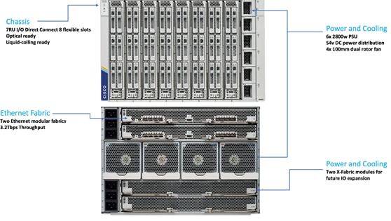
Figure 1 illustrates the major physical components involved in the FlashStack solution.
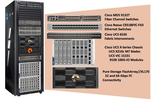
As shown in Figure 1, the reference architecture described in this document leverages the Pure Storage FlashArray//XL170 for shared storage, Cisco UCS X210 M7 Blade Server for Compute, Cisco MDS 9000 Series switches for storage connectivity using Fibre Channel protocol, Cisco Nexus 9000 Series Ethernet switches for networking element and Cisco Fabric Interconnects 6500 Series for System Management.
The FlashStack architecture components are connected and configured according to both Cisco and Pure best practices and provide the ideal platform for running a variety of enterprise workloads (including databases) with confidence. FlashStack can scale up for greater performance and capacity (adding compute, network, or storage resources independently and non-disruptively as needed), or it can scale out for environments that require multiple consistent deployments. The architecture brings together a simple, wire once solution that is SAN booted from FC and is highly resilient at each layer of the design.
Cisco and Pure Storage have also built a robust and experienced support team focused on FlashStack solutions, from customer accounts and technical sales representatives to professional services and technical support engineers. The support alliance between Pure Storage and Cisco gives customers and channel services partners direct access to technical experts who collaborate with cross vendors and have access to shared lab resources to resolve potential issues.
For more details and specifications of individual components, go to the References section where all the necessary links are provided.
This chapter contains the following:
● Cisco Unified Computing System X-Series
● Cisco UCS 9108-100G Intelligent Fabric Module (IFM)
● Cisco UCS X210c M7 Compute Node
● Cisco UCS 6536 Fabric Interconnects
● Cisco UCS and Intersight Security
● Cisco Nexus Switching Fabric
● Cisco MDS 9132T 32G Multilayer Fabric Switch
● Pure Cloud Block Store for Azure VMware Solution
● Microsoft Windows Server 2022
FlashStack architecture is built using the following infrastructure components for compute, network, and storage:
● Cisco Unified Computing System (Cisco UCS)
● Cisco Nexus 9000 Series Switches
● Cisco MDS 9000 Series Switches
● Pure Storage FlashArray
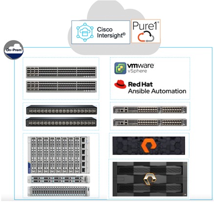
All the FlashStack components are integrated, so customers can deploy the solution quickly and economically while eliminating many of the risks associated with researching, designing, building, and deploying similar solutions from the foundation. One of the main benefits of FlashStack is its ability to maintain consistency at scale. Each of the component families shown in Figure 2, offers platform and resource options to scale-up performance or scale-out capacity while supporting the same features and functions.
This FlashStack solution described in this document comprises the following hardware and software components:
● Cisco 5th Generation Cisco UCS 6500 Fabric Interconnects to support 1/10/25 and 100 Gigabit Ethernet connectivity from various components.
● Cisco UCS X9508 Chassis with Cisco UCS X210c M7 compute nodes installed with 5th Generation Cisco VIC 15231 and with Cisco UCS 9108 100G Intelligent Fabric Module to connect the I/O fabric between the 6500 Fabric Interconnect and the Cisco UCS X9508 Chassis.
● High-Speed Cisco NX-OS based Nexus 93180YC-FX3 switching design to support up to 25/40/100GbE connectivity.
● High-Speed Cisco NX-OS based MDS 9132T switching design to support up to 32Gb end-to-end connectivity to support SCSI and NVMe over Fibre Channel.
● Pure Storage FlashArray//XL170 All Flash Storage is designed to support up to 64Gb with high-speed traditional Fibre Channel (FC) and NVMe over Fibre Channel connectivity and up to 100GbE Ethernet for iSCSI, NVMe/RoCE, NVMe/TCP connectivity for unifies block and file protocols including SMB and NFS.
The software components consist of:
● Cisco Intersight Assist virtual appliance to help connect the Pure Storage FlashArray and VMware vCenter with the Cisco Intersight platform.
● VMware vCenter 8.0 to manage the VMware vSphere 8.0 virtual environment.
● Pure Storage Plugin for vSphere Client for managing vSphere Virtual Volumes (vVols).
● Pure Storage Purity 6.3.3.
● Microsoft Windows Server 2022 and SQL Server 2022 databases.
Cisco Unified Computing System X-Series
The Cisco Unified Computing System (Cisco UCS) X-Series is a modular, next-generation data center platform that builds upon the unique architecture and advantages of the previous Cisco UCS 5108 system but with the following key enhancements that simplify IT operations:
● Cloud-managed infrastructure: With Cisco UCS X-Series, the management of the network infrastructure is moved to the cloud, making it easier and simpler for IT teams to respond quickly and at scale to meet the needs of your business. The Cisco Intersight cloud-operations platform allows you to adapt the resources of the Cisco UCS X-Series Modular System to meet the specific requirements of a workload. Additionally, you can seamlessly integrate third-party devices such as Pure Storage and VMware vCenter. This integration also enables global visibility, monitoring, optimization, and orchestration for all your applications and infrastructure.
● Adaptable system designed for modern applications: Today's cloud-native and hybrid applications are dynamic and unpredictable. Application and DevOps teams frequently deploy and redeploy resources to meet evolving requirements. To address this, the Cisco UCS X-Series provides an adaptable system that doesn't lock you into a fixed set of resources. It combines the density, manageability, and efficiency of blade servers with the expandability of rack servers, allowing you to consolidate multiple workloads onto a single platform. This consolidation results in improved performance, automation, and efficiency for both hybrid and traditional data center applications.
● Platform engineered for the future: The Cisco UCS X-Series is designed to adapt to emerging technologies with minimal risk. It is a modular system that can support future generations of processors, storage, nonvolatile memory, accelerators, and interconnects. This eliminates the need to purchase, configure, maintain, power, and cool separate management modules and servers. Cloud-based management through Intersight ensures automatic updates and access to new capabilities delivered through a software-as-a-service model.
● Broad support for diverse workloads: The Cisco UCS X-Series supports a broad range of workloads, reducing the need for different products which lowers support costs, training costs, and gives you more flexibility in your data center environment.
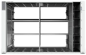
The Cisco UCS X-Series chassis is engineered to be adaptable and flexible. As shown in Figure 3, the Cisco UCS X9508 chassis has only a power-distribution midplane. This midplane-free design provides fewer obstructions for better airflow. For I/O connectivity, vertically oriented compute nodes intersect with horizontally oriented fabric modules, allowing the chassis to support future fabric innovations. Cisco UCS X9508 Chassis’ superior packaging enables larger compute nodes, thereby providing more space for actual compute components, such as memory, GPU, drives, and accelerators. Improved airflow through the chassis enables support for higher power components, and more space allows for future thermal solutions (such as liquid cooling) without limitations.
The Cisco UCS X-Series modular system is designed to take the current generation of the Cisco UCS platform to the next level with its design that will support future innovations and management in the cloud. Decoupling and moving platform management to the cloud allows the Cisco UCS platform to respond to features and scalability requirements much faster and more efficiently. Cisco UCS X-Series state-of-the-art hardware simplifies the datacenter design by providing flexible server options. A single server type that supports a broader range of workloads results in fewer different datacenter products to manage and maintain. The Cisco Intersight cloud management platform manages the Cisco UCS X-Series as well as integrates with third-party devices. These devices include VMware vCenter and Pure Storage to provide visibility, optimization, and orchestration from a single platform, thereby enhancing agility and deployment consistency.
Cisco UCS 9108-100G Intelligent Fabric Module (IFM)
Cisco UCSX-I-9508-100G Intelligent Fabric Modules In the end-to-end 100Gbps Ethernet design, for the Cisco UCS X9508 Chassis, the network connectivity is provided by a pair of Cisco UCSX-I-9108-100G Intelligent Fabric Modules (IFMs). Like the fabric extenders used in the Cisco UCS 5108 Blade Server Chassis, these modules carry all network traffic to a pair of Cisco UCS 6536 Fabric Interconnects (FIs). IFMs also host the Chassis Management Controller (CMC) for chassis management. In contrast to systems with fixed networking components, Cisco UCS X9508’s midplane-free design enables easy upgrades to new networking technologies as they emerge making it straightforward to accommodate new network speeds or technologies in the future.
Each IFM supports eight 100Gb uplink ports for connecting the Cisco UCS X9508 Chassis to the FIs and 8 100Gb or 32 25Gb server ports for the eight compute nodes. IFM server ports can provide up to 200 Gbps of unified fabric connectivity per compute node across the two IFMs. The uplink ports connect the chassis to the Cisco UCS FIs, providing up to 1600Gbps connectivity across the two IFMs. The unified fabric carries management, VM, and Fibre Channel over Ethernet (FCoE) traffic to the FIs, where server management traffic is routed to the Cisco Intersight cloud operations platform, FCoE traffic is forwarded to either native Fibre Channel interfaces through unified ports on the FI (to Cisco MDS switches) or to FCoE uplinks (to Cisco Nexus switches supporting SAN switching), and data Ethernet traffic is forwarded upstream to the data center network (using Cisco Nexus switches).
Cisco UCS X210c M7 Compute Node
The Cisco UCS X9508 Chassis is designed to host up to 8 Cisco UCS X210c M7 or X210c M6 Compute Nodes. The hardware details of the Cisco UCS X210c M7 Compute Nodes are shown in Figure 6.
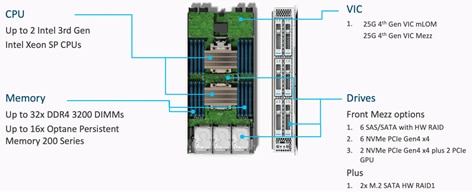
The Cisco UCS X210c M7 features:
● CPU: Up to 2x 4th Gen Intel Xeon Scalable Processors with up to 60 cores per processor and 2.625 MB Level 3 cache per core and up to 112.5 MB per CPU.
● Memory: Up to 32 x 256 GB DDR5-4800 DIMMs for a maximum of 8 TB of main memory.
● Disk storage: Up to 6 SAS or SATA drives or NVMe drives can be configured with the choice of an internal RAID controller or passthrough controllers. Two M.2 memory cards can be added to the Compute Node with optional hardware RAID.
● GPUs: The optional front mezzanine GPU module allows support for up to two HHHL GPUs. Adding a mezzanine card and a Cisco UCS X440p PCIe Node allows up to four more GPUs to be supported with a Cisco UCS X210c M7.
● Virtual Interface Card (VIC): Up to 2 VICs including an mLOM Cisco UCS VIC 15231 or an mLOM Cisco UCS VIC 15420 and a mezzanine Cisco UCS VIC card 15422 can be installed in a Compute Node.
● Security: The server supports an optional Trusted Platform Module (TPM). Additional security features include a secure boot FPGA and ACT2 anticounterfeit provisions.
Intel Xeon Scalable processors feature the broadest and widest set of built-in accelerator engines for today’s most demanding workloads. Whether on-prem, in the cloud, or at the edge, Intel Accelerator Engines can help take your business to new heights, increasing application performance, reducing costs, and improving power efficiency.
With 4th-generation Intel Xeon Scalable processors shipped with integrated hardware accelerators for offloading most common tasks like compression, encryption and so on, from applications to its accelerators.
For more details on the various built-in accelerator engines supported by Intel, go to: https://www.intel.in/content/www/in/en/now/xeon-accelerated/accelerators-eguide.html
Microsoft and Intel worked together to enable the support for offloading backup compression using the Intel QAT hardware accelerator. The Microsoft SQL Server 2022 supports offloading and backup acceleration using the Intel QAT accelerator and improves the backup performance. See System Validation and Testing for the tests and results.
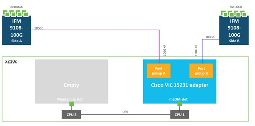
Cisco UCS Virtual Interface Card 15231
Cisco UCS X210c M7 Compute Nodes support multiple Cisco UCS VIC cards. In this solution, Cisco UCS VIC 15231 is used for the validation.
Cisco UCS VIC 15231 fits the mLOM slot in the Cisco UCS X210c Compute Node and enables up to 100 Gbps of unified fabric connectivity to each of the chassis IFMs for a total of 200 Gbps of connectivity per server. Cisco UCS VIC 15231 connectivity to the IFM and up to the fabric interconnects is delivered through 100Gbps. Cisco UCS VIC 15231 supports 512 virtual interfaces (both FCoE and Ethernet) along with the latest networking innovations such as NVMeoF over FC or TCP, VxLAN/NVGRE offload, and so forth.
Cisco UCS 6536 Fabric Interconnects
The Cisco UCS Fabric Interconnects (FIs) provide a single point for connectivity and management for the entire Cisco Unified Computing System. Typically deployed as an active/active pair, the system’s FIs integrate all components into a single, highly available management domain controlled by Cisco Intersight. Cisco UCS FIs provide a single unified fabric for the system, with low-latency, lossless, cut-through switching that supports LAN, SAN, and management traffic using a single set of cables.

The Cisco UCS 6536 utilized in the current design is a 36-port Fabric Interconnect. This single RU device includes up to Thirty-Six 10/25/40/100 Gbps Ethernet ports, four 8/16/32-Gbps Fibre Channel ports supporting connectivity using 4x32 Gbps breakouts on ports 33-36. All 36 ports support breakout cables or QSA interfaces.
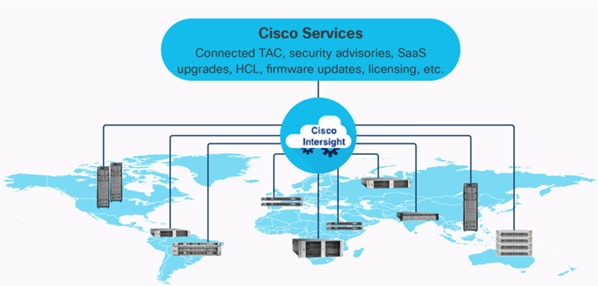
The Cisco Intersight platform is a Software-as-a-Service (SaaS) infrastructure lifecycle management platform that delivers simplified configuration, deployment, maintenance, and support. The Cisco Intersight platform is designed to be modular, so you can adopt services based on your individual requirements. The platform significantly simplifies IT operations by bridging applications with infrastructure, providing visibility and management from bare-metal servers and hypervisors to serverless applications, thereby reducing costs and mitigating risk. This unified SaaS platform uses a unified Open API design that natively integrates with third-party platforms and tools.
The main advantages of the Cisco Intersight infrastructure services are as follows:
● Simplify daily operations by automating many daily manual tasks.
● Combine the convenience of a SaaS platform with the capability to connect from anywhere and manage infrastructure through a browser or mobile application.
● Stay ahead of problems and accelerate trouble resolution through advanced support capabilities.
● Gain global visibility of infrastructure health and status along with advanced management and support capabilities.
● Upgrade to add workload optimization and other services when needed.
Cisco Intersight is a pow management platform that enables the centralized control of diverse infrastructure components, including both 3rd party infrastructure such as Pure Storage and VMware vCenter, as well as non-Cisco UCS infrastructure like Cisco MDS and Cisco Nexus switches. With Cisco Intersight, you can have a comprehensive, global, and consolidated view of your entire infrastructure from one place.
A data center could have multiple devices that do not connect directly with Cisco Intersight. Any device that is supported by Cisco Intersight, but does not connect directly with it, will need a connection mechanism. This is where Cisco Intersight Assist comes into picture and provides that connection mechanism. It serves as a proxy, enabling the connection and management of third-party and non-Cisco UCS infrastructure components. For each supported endpoint, Intersight Assist ships with an endpoint connector (for example, VMware vCenter or Pure Storage Connector) that communicates with the endpoint using REST APIs. The claiming process involves claiming Intersight Assist as a target endpoint in Intersight and then using this to claim other 3rd party endpoint devices with the Claim Through Intersight Assist option.
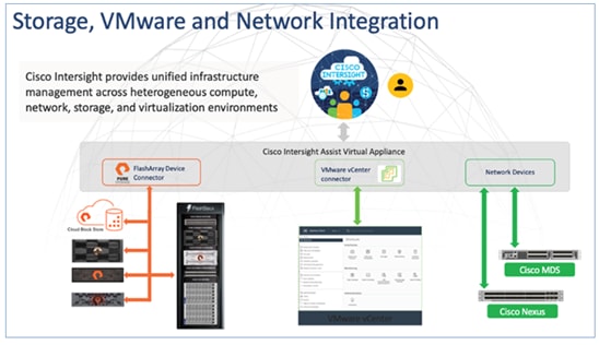
In the context of the FlashStack solution, the following third-party and non-Cisco UCS infrastructure components can be claimed and managed from Intersight through the assistance of Cisco Intersight Assist:
● VMware vCenter
● Pure Storage FlashArray (including Cloud Block Store)
● Cisco MDS SAN switches
● Cisco Nexus switches
For more information on Cisco Intersight Assist, see: Cisco Intersight Virtual Appliance and Intersight Assist Getting Started Guide, 1.0.9
The Cisco Intersight platform uses a new subscription-based license model now with two tiers. You can purchase a subscription duration of one, three, or five years and choose the required Cisco UCS server volume tier for the selected subscription duration. For Cisco UCS M6 and below servers, each Cisco endpoint can be claimed into Intersight at no additional cost (no license) and can access base-level features listed in the Intersight Licensing page referenced below. All Cisco UCS M7 servers require either an Essentials or Advantage license listed below. You can purchase any of the following Cisco Intersight licenses using the Cisco ordering tool:
● Cisco Intersight Essentials: The Essentials includes Lifecycle Operations features, including Cisco UCS Central and Cisco UCS-Manager entitlements, policy-based configuration with server profiles (IMM), firmware management, Global Monitoring and Inventory, Custom Dashboards, and evaluation of compatibility with the Cisco Hardware Compatibility List (HCL). Also, Essentials includes Proactive Support features, including Proactive RMA, Connected TAC, Advisories, and Sustainability.
● Cisco Intersight Advantage: Advantage offers all the features of the Essentials tier plus In-Platform Automation features such as Tunneled KVM, Operating System Install Automation, Storage/Virtualization/Network Automation, and Workflow Designer. It also includes Ecosystem Integrations for Ecosystem Visibility, Operations, Automation, and ServiceNow Integration.
Servers in the Cisco Intersight Managed Mode require at least the Essentials license. For more information about the features provided in the various licensing tiers, see https://intersight.com/help/saas/getting_started/licensing_requirements/lic_infra.
Cisco UCS and Intersight Security
From a Security perspective, all Cisco UCS user interfaces are hardened with the latest security ciphers and protocols including redirection of http to https, password and password expiry policies, integration with secure authentication systems, and so on. Additionally, Cisco UCS servers support confidential computing (both Intel SGX and AMD based), although confidential computing is not addressed in this CVD. Finally, almost all Cisco UCS servers now sold come with Trusted Platform Modules (TPMs), that in VMware allows attestation of Unified Extended Firmware Interface Forum (UEFI) secure boot, which allows only securely signed code to be loaded. Many of the latest available operating systems, such as Microsoft Windows 11 require a TPM. The latest versions of VMware allow the assignment of a virtual TPM to VMs running operating systems that require a TPM.
The Cisco Nexus 9000 Series Switches offer both modular and fixed 1/10/25/40/100 Gigabit Ethernet switch configurations with scalability up to 60 Tbps of nonblocking performance with less than five-microsecond latency, wire speed VXLAN gateway, bridging, and routing support.
The Cisco Nexus 93180YC-FX3 Switch (Figure 10) is a 1RU switch that supports 3.6 Tbps of bandwidth and 1.2 Bpps. The 48 downlink ports on the 93180YC-FX3 can support 1/10/25-Gbps Ethernet, offering deployment flexibility and investment protection. The 6 uplink ports can be configured as 40 or 100-Gbps Ethernet, offering flexible migration options. The Cisco Nexus 93180YC-FX3 switch supports standard PTP telecom profiles with SyncE and PTP boundary clock functionality for telco datacenter edge environments.
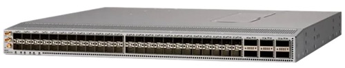
Cisco MDS 9132T 32G Multilayer Fabric Switch
The Cisco MDS 9132T 32G Multilayer Fabric Switch is the next generation of the highly reliable, flexible, and low-cost Cisco MDS 9100 Series switches. It combines high performance with exceptional flexibility and cost effective-ness. This powerful, compact one Rack-Unit (1RU) switch scales from 8 to 32 line-rate 32 Gbps Fibre Channel ports.
![]()
The Cisco MDS 9132T delivers advanced storage networking features and functions with ease of management and compatibility with the entire Cisco MDS 9000 family portfolio for reliable end-to-end connectivity. This switch also offers state-of-the-art SAN analytics and telemetry capabilities that have been built into this next-generation hardware platform. This new state-of-the-art technology couples the next-generation port ASIC with a fully dedicated network processing unit designed to complete analytics calculations in real time. The telemetry data extracted from the inspection of the frame headers are calculated on board (within the switch) and, using an industry-leading open format, can be streamed to any analytics-visualization platform. This switch also includes a dedicated 10/100/1000BASE-T telemetry port to maximize data delivery to any telemetry receiver, including Cisco Data Center Network Manager.
The Pure Storage FlashArray Family delivers software-defined all-flash power and reliability for businesses of every size. FlashArray is all-flash enterprise storage that is up to 10X faster, space and power efficient, reliable, and far simpler than other available solutions. Compared to traditional performance disk arrays, FlashArray costs less with total cost of ownership (TCO) savings of up to 50%. At the top of the FlashArray line is the new FlashArray//XL; this new platform is designed for today’s higher-powered multi core CPUs, allowing //XL to increase performance even over our FlashArray//X models, with more power to take apps to the next level. //XL represents next-level scale and performance for high-demand enterprise applications. The //XL platform enhancements give higher performance, higher capacity density per RU, and higher scale with better resiliency. By being engineered for next-gen CPU and flash technologies to future-proof your investment, you can achieve workload consolidation with room to grow in place, with less frequent servicing by IT staff.
Pure Cloud Block Store with Azure VMware Solution
Pure Storage's Cloud Block Store (CBS) is a software defined storage solution powered by the Purity//FA Operating Environment (OE), which uses the native resources of either Amazon Web Services or Microsoft Azure to enhance storage services with enterprise features, ensuring consistent management without any customer tuning.
Pure Storage provides an external block storage for Microsoft’s Azure VMware Solution to improve TCO for VMware workloads in Azure. For customers with storage-intensive VMware workloads, Pure Cloud Block Store™ provides the flexibility to match their Azure VMware Solution compute needs with the storage capacity needs—optimizing the cost in the cloud.
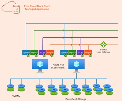
Architecture
Cloud Block Store's high-level architecture consists of two Azure virtual machines acting as controllers and Azure managed disks for the NVRAM and persistent storage (PremiumV2 or Ultra SSDs). The Cloud Block Store controllers process data and provide enterprise data services such as data reduction, snapshots, encryption, and replication. Two managed disks will be deployed for NVRAM and 14 managed disks for persistent storage. Cloud Block Store instances can be non-disruptively upgraded (NDU) with additional capacity by upgrading the managed disk sizes. All Cloud Block Store NDU's are performed by Pure Storage Support in an automated fashion which removes any additional effort from the customer.
Highlights
● Data Efficiency - industry leading data reduction, space saving snapshots and cloning reduces cloud storage costs, enables fast and easy data portability, and increases data processing agility
● Cloud Data Protection - built in replication, disaster recovery and business continuity between public and private cloud targets along with higher availability protects your business from downtime in the cloud or on-premises.
● Evergreen//One™ - unifies experience and storage between on-premises and cloud to deliver a flexible hybrid cloud experience
● Application Migration - When migrating data to the public cloud, the requirement to redesign existing applications deployed on-premises is a common challenge. The enterprise data storage services of Cloud Block Store allow customers to easily migrate and run their existing mission critical data in the public cloud without redesigning their applications. Cloud Block Store shares a common abstraction layer as the Pure Storage Array for both management and data access which allows customers to preserve the same operational workflows, scripts, and orchestration tools. Cloud Block Store's built-in resiliency allows for the most mission critical data to run without requiring the application layer to manage data availability
● Reduce Storage Costs - Once customers successfully make the transition to Azure with Cloud Block Store, they can realize the benefits of Cloud Block Store enterprise features. Customers can consolidate data onto Cloud Block Store to take advantage of Purity's data reduction capabilities. Existing FlashArray customers can expect the same data reduction ratio already observed on their physical FlashArray. Thin Provisioning with Cloud Block Store further improves a customer's total efficiency. Developers can confidently provision volumes as large as needed without the cost concern or the need to constantly resize their disks.
● Increase Availability - In production environments, data availability and protection is the number one priority. Customers can rely on the highly efficient snapshot capabilities of Cloud Block Store to provide periodic point-in-time volume snapshots to protect from unintentional data changes. Additionally, customers who require the highest form of data availability can replicate their data between availability zones or regions. ActiveCluster allows data to be synchronously replicated between Cloud Block Store instances in different availability zones. This feature allows for automatic and transparent application failovers in the event of a complete outage of an availability zone. For larger-scale regional outage protection, data can also be replicated asynchronously between Cloud Block Store instances residing in different regions.
Disaster Recovery and Migration using Replication
The Purity Operating Environment enables both the FlashArray and Cloud Block Store to use the same replication technology despite running on two different environments. This feature opens the door to new use cases including disaster recovery, data migration, and back-up to the public cloud.
For disaster recovery (DR) solutions, many customers search for ways to incorporate the public cloud. Leveraging the public cloud alleviates the need to manage remote secondary or tertiary physical data centers. In a disaster recovery solution, customers can use Cloud Block Store as a replication target. During a DR failover event, customers can use a replicated snapshot volume on Cloud Block Store to instantaneously clone and attach to the respective application hosts in the public cloud. For protection against a single AZ or regional failure, Cloud Block Store can replicate its own source volumes to other Cloud Block Store instances.
Customers looking to migrate data from their on-premises data center to the public cloud can rely on Cloud Block Store to not only provide the vehicle to move their data, but also provide ongoing enhanced data services. Once data volumes are replicated to Cloud Block Store, customers can easily attach the volumes to the application compute instances over iSCSI with the same simple steps as on a FlashArray.
Hybrid Cloud
Cloud Block Store provides an abstraction layer that allows applications to be agnostic to the private or public cloud that it runs on. Pure Storage's vision is to enable customers to seamlessly move their data between all the major public cloud vendors using the native replication capabilities of Cloud Block Store. Furthermore, Cloud Block Store's data reduction is preserved when data is replicated, thus reducing the required bandwidth, time, and potential data egress costs. Customers are protected from being locked into any single environment and are afforded the flexibility to migrate or replicate data with minimal effort.
Purity for FlashArray (Purity//FA)
Every FlashArray is driven by Purity Operating Environment software. Purity//FA implements advanced data reduction, storage management, and flash management features, enabling customers to enjoy tier 1 data services for all workloads. Purity software provides proven 99.9999-percent availability over 2 years, completely non disruptive operations, 2X better data reduction, and the power and efficiency of DirectFlashTM. Purity also includes enterprise-grade data security, comprehensive data-protection options, and complete business continuity with an ActiveCluster multi-site stretch cluster. All these features are included with every Pure Storage array.
The Pure Storage FlashArray product line includes FlashArray//C, FlashArray//X, FlashArray//XL, and FlashArray//E.
FlashArray//XL Specification
Table 1 lists both the capacity and physical aspects of various FlashArray systems.
Table 1. FlashArray//XL170 Specifications
|
|
Capacity |
Physical |
| //XL170 |
Up to 5.5 PB/5.13 PiB effective capacity** Up to 1.4 PB/1.31 PiB raw capacity* |
5RU, 1850-2355 watts (normal - peak) 167.0lb. (75.7kg) fully loaded; 8.72 x 18.94 x 29.72 in |
| //XL130 |
Up to 3.8 PB/3.5PiB effective capacity Up to 1024TB/932.1TiB raw capacity |
5-11U, 1550-2000 watts (normal - peak) 167.0lb. (75.7kg) fully loaded; 8.72 x 18.94 x 29.72 in |
| DirectFlash Shelf |
Up to 1.9 PB effective capacity Up to 512 TB / 448.2 TiB raw capacity |
3U; 460–500 watts (nominal–peak) 87.7 lbs. (39.8 kg) fully loaded; 5.12” x 18.94” x 29.72” |
** Effective capacity assumes high availability, RAID, and metadata overhead, GB-to-GiB conversion, and includes the benefit of data reduction with always-on inline deduplication, compression, and pattern removal. Average data reduction is calculated at 5-to-1 and does not include thin provisioning.
* FlashArray//XL will only support NVMe DirectFlash Modules.
Table 2 lists the various connectivity options using onboard and host I/O cards.
Table 2. FlashArray//XL170 Connectivity
| Chassis |
Onboard ports (per controllers) |
Host I/O cards (3 slots/controller) |
| //XL170 & //XL130 |
Two 1-/10-/25-GE iSCSI/RoCE |
2 -port 10-/25 or 100-Gb NVMe/RoCE |
| //XL170 & //XL130 |
Four 10/25-GE replication |
2-port 32-/64-Gb Fibre Channel (NVMe-oF Ready) |
| //XL170 & //XL130 |
Two 1-Gb management ports |
4-port 32/64 Gb Fibre Channel (NVMe-oF Ready) |
Protection Groups
Protection Groups are designed to protect a volume, set of volumes, Host or Host Group from human and software errors using techniques like Snapshot (point-in-time copies) and Remote Replication (to a remote on-prem or cloud Pure Storage).
Snapshots
A snapshot is a point-in-time image of a volume. Pure Storage FlashArray supports following two types of snapshots:
● Crash-consistent Snapshots: Snapshots capture a point-in-time representation of a volume, without needing to create a second discrete copy. It does not deal with in-transit updates (no I/O quiescing, flushing, and so on) therefore it is much faster and has zero impact on the application performance. Crash-consistent snapshot works with SQL Server’s write-ahead logging protocol to provide a recoverable database but not point-in-time recovery with transactional logs. The point of recovery is the time of snapshot plus SQL Server crash recovery.
● Application-Consistent: These snapshots ensure consistency of the application by freezing ongoing updates and flushing updated memory pages to disk before taking a snapshot. For SQL Server 2019 and prior, the VSS framework is required to take Application Consistent snapshots. While the freezing of I/O on the SQL Server using VSS may take longer than a few seconds, the subsequent snapshot operation on FlashArray is nearly instantaneous. Starting in SQL Server 2022, VSS is no longer required, and Application Consistent snapshots may now be orchestrated with the new T-SQL Snapshot feature. This also means that the freezing of SQL Server is also greatly reduced; in fact, read traffic is no longer halted, only write traffic.
On FlashArray, because volumes are logical constructs, snapshots merely copy the “state” of the volume at time of snapshot. This means snapshots do not consume additional capacity and can be manipulated nearly instantaneously. This is extremely beneficial for SQL Server databases, as it enables one to snapshot Very Large Databases (VLDBs) and clone “copies” to other SQL Servers nearly instantaneously, regardless of the size of data. Because snapshots take place at the storage volume level, using vSphere Virtual Volumes (vVols) for storing SQL Server virtual machine disks brings more granular control and seamless data management and recovery of volumes.
Pure1
Pure1, a cloud-based management, analytics, and support platform, expands the self-managing, plug-n-play design of Pure all-flash arrays with the machine learning predictive analytics and continuous scanning of Pure1 Meta to enable an effortless, worry-free data platform.
Pure1 Manage
Pure1 Manage is a SaaS-based offering that allows customers to manage their array from any browser or from the Pure1 Mobile App with nothing extra to purchase, deploy, or maintain. From a single dashboard, customers can manage all their arrays and have full storage health and performance visibility.
Pure1 Analyze
Pure1 Analyze delivers true performance forecasting, giving customers complete visibility into the performance and capacity needs of their arrays, now and in the future. Performance forecasting enables intelligent consolidation and workload optimization.
Pure1 Support
Pure Storage support team with the predictive intelligence of Pure1 Meta delivers unrivaled support that’s a key component in FlashArray 99.9999% availability. Some of the customer issues are identified and fixed without any customer intervention.
Pure1 META
The foundation of Pure1 services, Pure1 Meta is global intelligence built from a massive collection of storage array health and performance data. By continuously scanning call-home telemetry from Pure’s installed base, Pure1 Meta uses machine learning predictive analytics to help resolve potential issues, optimize workloads, and provide accurate forecasting. Meta is always expanding and refining what it knows about array performance and health.
Pure1 VM Analytics
Pure1 helps you narrow down the troubleshooting steps in your virtualized environment. VM Analytics provides you with a visual representation of the IO path from the VM all the way through to the FlashArray. Other tools and features guide you through identifying where an issue might be occurring to help eliminate potential candidates for a problem.
VM Analytics doesn’t only help when there’s a problem. The visualization allows you to identify which volumes and arrays particular applications are running on. This brings the whole environment into a more manageable domain.
VMware vSphere 8.0
VMware vSphere is a virtualization platform for holistically managing large collections of infrastructures (resources including CPUs, storage, and networking) as a seamless, versatile, and dynamic operating environment. Unlike traditional operating systems that manage an individual machine, VMware vSphere aggregates the infrastructure of an entire datacenter to create a single powerhouse with resources that can be allocated quickly and dynamically to any application in need.
VMware vSphere 8.0 has several improvements and simplifications including, but not limited to:
● Limits with VMware vSphere 8.0 have been increased including the number of GPU devices increased to 8, the number of ESXi hosts that can be managed by Lifecycle Manager is increased from 400 to 1000, the maximum number of VMs per cluster is increased from 8,000 to 10,000, and the number of VM DirectPath I/O devices per host is increased from 8 to 32.
● Security improvements include adding an SSH timeout on ESXi hosts, a TPM Provisioning policy allowing a vTPM to be replaced when cloning VMs, and TLS 1.2 as the minimum supported TLS version.
● Implementation of VMware vMotion Unified Data Transport (UDT) to significantly reduce the time to storage migrate powered off virtual machines.
● Lifecycle Management improvements including VMware vSphere Configuration Profiles as a new alternative to VMware Host Profiles, staging cluster images and remediating up to 10 ESXi hosts in parallel instead of one at a time.
● New Virtual Hardware in VM hardware version 20 supporting the latest guest operating systems, including Windows 11.
● Distributed Resource Scheduler and vMotion improvements.
● Implementation of the VMware Balanced Power Management Policy on each server, which reduces energy consumption with minimal performance compromise.
● Implementation of VMware Distributed Power Management, which along with configuration of the Intelligent Platform Management Interface (IPMI) on each Cisco UCS server allows a VMware host cluster to reduce its power consumption by powering hosts on and off based on cluster resource utilization.
For more information about VMware vSphere and its components, go to: https://www.vmware.com/products/vsphere.html
The FlashStack solution supports VMware Virtual Volumes (vVols) that provides a more granular control of your shared storage environment. VMware vVols is a storage technology that provides policy-based, granular storage configuration for VM storage. When a VM is created, the administrator selects a VM storage policy to associate with it. On the back-end storage array, the storage is provisioned for the VM on a per-VM basis (with 1 config vVol per VM, 1 data vVol per disk) without the VMware administrator being aware of the array specific configuration. Instead, VMware administrators provision storage using native VMware interfaces. Through API-based interaction with an underlying array, VMware administrators can maintain storage configuration compliance using only native VMware interfaces. The Pure Storage FlashArray Plugin for the vSphere Web Client provides the APIs necessary to create, manage, and use vVols from VMware vCenter.
With SCSI or NFS transports, ESXi hosts use a logical I/O proxy, called the protocol endpoint, to communicate with virtual volumes. ESXi uses protocol endpoints to establish a data path on demand from virtual machines to their respective virtual volumes. Each virtual volume is bound to a specific protocol endpoint. When a virtual machine on the host performs an I/O operation, the protocol endpoint directs the I/O to the appropriate virtual volume. Typically, a storage system requires just a few protocol endpoints. A single protocol endpoint can connect to hundreds or thousands of virtual volumes.
The VMware vSphere APIs for Storage Awareness (VASA) is a VMware interface for out-of-band communication between VMware ESXi, vCenter and storage arrays. The arrays’ VASA providers are instances of the VASA service which are registered with the vCenter Server. Pure Storage hosts the VASA provider as redundant instances of the VASA service running on each controller; there is no separate installation or configuration. VASA allows for advanced management functionality and reporting at both VMs and per-disk level of granularity.
Figure 14 illustrates high level architecture of the vVols.
Some of the benefits of VMware vVols are:
● Virtual Disk Granularity: Each virtual disk is a separate volume on the array with its own unique properties.
● Automatic Provisioning: When a VMware administrator requests a new virtual disk for a VM, VMware automatically directs the array to create a volume and present it to the VM. Similarly, when a VMware administrator resizes or deletes a virtual disk, VMware directs the array to resize or remove the volume.
● Array-level VM Visibility: Because arrays recognize both VMs and their virtual disks, they can manage and report on performance and space utilization with both VM and individual virtual disk granularity.
● Storage Policy Based Management: With visibility to individual virtual disks, arrays can take snapshots and replicate volumes at the precise granularity required. VMware can discover an array’s virtual disks and allow VMware administrators to manage each vVol’s capabilities either ad hoc or by specifying policies. If a storage administrator overrides a vVol capability configured by a VMware administrator, the VMware administrator is alerted to the non-compliance.
Virtual Volume Best Practices and Other Considerations:
● A VM's Config vVol stores the files required to build and manage the VM. Ensure that the Config vVol is part of an existing Pure Storage FlashArray Protection Group. Alternately, if you are using a storage policy that includes snapshot or if you prefer manual snapshots, Config vVol should be part of these snapshots. This will help with the VM recovery process if the VM is deleted.
● Create a local array admin user to register the storage provider instead of using the local “pureuser” account.
● vCenter Server should not reside on vVols.
● ESXi Hosts, vCenter Server and FlashArray should synchronize time to the same NTP Server.
● Use the Pure Storage Plugin for the vSphere Client to register the Pure Storage FlashArray storage provider and mount the vVols datastore.
● A single PE utilizing the default device queue depth is sufficient in the design.
● vVol Virtual Disk resizing should be completed from the vSphere Client and not from the FlashArray GUI.
● TCP port 8084 must be open and accessible from vCenter Servers and ESXi hosts to the FlashArray that will be used for vVol.
Windows Server 2022 is the latest OS platform release from Microsoft. Windows Server 2022 is an excellent platform for running Microsoft SQL Server 2022 databases. It offers new features and enhancements related to security, patching, domains, clusters, storage, and support for various new hardware features, and so on. It enables Windows Server to provide best-in-class performance and a highly scalable platform for deploying SQL Server databases.
SQL Server 2022 (16.x) is the latest relational database from Microsoft and builds on previous releases to grow SQL Server as a platform that gives you choices of development languages, data types, on-premises or cloud environments, and operating systems. It offers various enhancements and new features that enables SQL Server deployments to be more reliable, highly available, performant, and secured than ever. SQL Server 2022 can leverage new hardware capabilities from partners like Intel to provide extended capabilities. For example, now it can leverage Intel Quick Assist Technology (QAT) for offloading backup compression thereby improving backup and restore performance.
For more details about the new capabilities of SQL Server 2022, go to: https://learn.microsoft.com/en-us/sql/sql-server/what-s-new-in-sql-server-2022?view=sql-server-ver16
This chapter contains the following:
● VMware vSphere – ESXi Networking Design
The FlashStack solution in this CVD was designed to address the following key goals:
● Resilient design across all layers of the infrastructure with no single point of failure.
● Scalable design with the ability to independently add compute, storage, and network bandwidth as needed.
● Modular design where sub-system components and resources can be changed, expanded, or upgraded as needed. Also, the design can be replicated as a unit to meet growth and expansion requirements.
● Flexible design with design options for the different subsystems in the solution, including the individual components used, storage configuration and connectivity options.
● Best-practices based design, incorporating design, technology, and product best practices.
● Simplify deployments through automation and make the solution available as Infrastructure as Code (IaC).
● Simplify operations using SaaS management where possible.
The high-level design of the FlashStack solution is shown in Figure 15.
The FlashStack solution is FC-based solution with storage access to Pure Storage FlashArray//XL170 array over traditional Fibre Channel connections. The solution includes the latest generation of Cisco UCS hardware running VMware vSphere 8.0. The solution incorporates design, technology, and product best practices to deliver a highly scalable and available architecture with no single point of failure. The compute, storage, network, and virtualization layers of the end-to-end design is built using the following components.
● Cisco UCS X9508 server chassis with 2 x Cisco UCS X9108-100G Intelligent Fabric Modules (IFMs) where 4 x 100GbE ports on each IFM connect to a pair of Cisco UCS Fabric Interconnects to provide upstream connectivity and all networks within and outside the Enterprise data center, including external networks.
● Cisco UCS X210c M7 compute nodes using 2 x 4th generation Intel Xeon Scalable processors with 512GB of DDR5 memory that can be increased up to a max of 8TB. The server is equipped with a Cisco UCS VIC 15231 network adaptor in the modular LAN On Motherboard (mLOM) slot and provides up to 200Gbps (2x100Gbps) of unified fabric connectivity from each compute node to the 100G Intelligent Fabric Modules (IFMs) on the Cisco UCS X-Series chassis.
● Pair of Cisco UCS 6536 Fabric Interconnects (FIs) provides line-rate, low-latency, lossless connectivity for LAN, SAN and management traffic from the Cisco UCS X-Series and Cisco UCS C-Series servers to Pure Storage and other upstream and external networks. The Cisco Fabric Interconnects provide:
◦ 4 x 32Gb FC connectivity to a Pure Storage FlashArray//XL170 through a pair of Cisco MDS switches.
◦ 2x100GbE uplink network connectivity to a pair of Cisco Nexus switches deployed in a vPC configuration and provide uplink connectivity to other internal and external networks.
● Pair of Cisco Nexus 93180YC-FX3 switches in NX-OS mode provide upstream connectivity to the Cisco UCS 6536FIs, enabling 100Gbps or higher speeds for connecting the FlashStack compute and storage infrastructure to other parts of an Enterprise’s internal and external networks as needed.
● Pair of Cisco MDS 9132T FC switches provides 32Gbps Fibre Channel connectivity to a SAN fabric with consistent low-latency performance using a chip-integrated non-blocking arbitration. MDS can operate in either switch mode or NPV mode and includes a dedicated Network Processing Unit (NPU) per port for real-time analytics calculations. The switch can inspect FC and SCSI headers at wire speed on every flow and analyze the flows on the switch itself. By using an industry-leading open format, the telemetry data can then be streamed to any analytics-visualization platform. This switch also includes a dedicated 10/100/1000BASE-T telemetry port to maximize data delivery to any telemetry receiver including Cisco Data Center Network Manager. Note that since this solution uses Cisco UCS 6536FIs running in NPV mode, the MDS switches will not be used in NPV mode in this CVD. Instead, the MDS switches will be deployed in Fibre Channel switching mode with NPIV mode.
● Pure Storage FlashArray//XL170 connects to the Cisco MDS 9132T switches using 32-Gbps Fibre Channel connections for Fibre Channel SAN connectivity.
● VMware vSphere 8.0 is deployed on the Cisco UCS X210M7 blades to host virtualized workloads.
● Cisco Intersight in Intersight Managed Mode (IMM) will manage the infrastructure from the cloud.
In this solution, VMware ESXi 8.0 virtual environment is tested and validated for deploying SQL Server 2022 databases on virtual machines running Windows Server 2022 guest operating system. The ESXi hosts are configured to boot from the Pure Storage using Fibre Channel. SQL Server virtual machine OS and Database files are stored over vSphere vVols using Fibre Channel protocol. Table 3 lists the software and hardware components along with image versions used in this solution.
Table 3. Software Components and Hardware
| Layer |
Device |
Image |
Quantity |
| Network |
Cisco Nexus 9000 C93180YC-FX3 Cisco MDS 9132T |
9.3(7) 9.2(2) |
2 2 |
| Compute |
Cisco UCS Fabric Interconnects 6536 Cisco UCS 9108-100G IFM X210c M7 compute nodes BIOS Cisco VIC 15231 nenic Drivers Cisco VIC 15231 nfnic Drivers |
4.3(2.230117) 4.3(2a) 5.2(0.230041) 1.0.6.0 5.0.0.43 |
2 2 4 1
|
| VMware |
VMware vSphere vCenter Appliance VMware vSphere ESXi |
8.0.1 8.0.1
|
1 |
| Cisco Intersight Assist Appliance |
Cisco Intersight Assist Appliance |
1.0.9 |
|
| Storage |
Pure Storage FlashArray Purity Version Pure Storage VMware vSphere Plugin Clou Block Store Purity//FA Version
VASA provider |
FlashArray//XL170 Purity 6.3.3 5.3.5 CBS on Azure Cloud 6.4.10 3.5 |
1 HA Pair with 30x 3.9TB NVMe SSDs and each controller equipped with 1x 324-port 32Gbps FC Adapter
|
| Guest OS |
Microsoft Windows Server 2022 Datacenter Eval |
20348.587 |
|
| Database |
Microsoft SQL Server 2022 |
16.0.1000.6 |
|
| Workload Testing Tool |
HammerDB |
4.9 |
|
Figure 16 details the cabling used for this validation. As shown, the Pure Storage FlashArray is connected to Cisco UCS Fabric Interconnects through Cisco MDS switches using 32Gb FC links. Cisco UCS 9108 blade chassis is connected to the Cisco UCS Fabric interconnects through IFM modules using 2x 100Gbps Ethernet connections on each side of the Fabric. The Cisco UCS Fabric Interconnects are connected to Cisco MDS switches over 100G – 4x 32GB FC break out cables for FC storage traffic.
The Cisco UCS Fabric Interconnects are connected to Cisco Nexus switches through 100Gbps connections. Finally, the Nexus switches are connected to customer network. Each Cisco UCS fabric interconnect and Cisco Nexus switch is connected to the out-of-band network switch, and each Pure controller has a connection to the out-of-band network switch.
IMPORTANT! For this FlashStack with SQL Server database validation, on each storage controller only two FC ports, with scsi-fc services enabled, are used.
VLAN Configuration
Table 4 lists the VLANs configured for setting up the FC-based FlashStack environment along with their usage.
| VLAN ID |
Name |
Usage |
| 2 |
Native-VLAN |
Use VLAN 2 as native VLAN instead of default VLAN (1) |
| 1060 |
OOB-MGMT-VLAN |
Out-of-band management VLAN to connect management ports for various devices |
| 1061 |
MGMT-VLAN |
In-band management VLAN utilized for all in-band management connectivity - for example, ESXi hosts, VM management, and so on |
| 1062 |
SQL-MGMT |
For SQL Client connectivity |
| 3000 |
vMotion |
VMware vMotion traffic |
VSAN Configuration
Table 5 lists the VSAN configured for setting up the FC-based FlashStack environment along with their usage.
| VSAN ID |
Name |
Usage |
| 103 |
VSAN-A |
For storage traffic through MDS Fabric-A |
| 104 |
VSAN-B |
For storage traffic through MDS Fabric-A |
Pure Storage FlashArray – Storage Design
To set up Pure Storage FlashArray, you must configure the following items:
● Volumes
◦ ESXi boot LUNs: These LUNs enable ESXi host boot from SAN functionality using Fibre Channel.
◦ The vSphere environment: vSphere uses the infrastructure datastore(s) to store the virtual machines. These volumes can be exposed to the ESXi hosts using traditional Fibre Channel protocol.
◦ vSphere Virtual Volumes for Application data storage: vVols are used for storing SQL Server VM’s virtual disks. For each virtual disk you add for a VM, a volume (data volumes) will be created on the Pure storage. In addition, two more volumes will be created ( one for config and other volume for swap).
● Hosts
◦ All FlashArray ESXi hosts are defined using the FC WWNs (scsi-fc based initiators).
◦ Add every active initiator for a given ESXi host.
● Host groups
◦ All ESXi hosts in a VMware cluster are part of the host group.
◦ Host groups are used to mount VM infrastructure application storage datastores in the VMware environment so that all the ESXi hosts that part of Host Group will get access storage volumes.
The ESXi host is configured with two vHBAs for storage access. vHBA-A will be connected to Pure storage via Fabric-A and vHBA-B will be connected to storage via Fabric-B. These HBA adapters will be used for ESXi boot traffic as well as SQL Server data traffic. Figure 17 depicts the storage layout used for this validation.
VMware vSphere – ESXi Networking Design
Multiple vNICs and vHBAs are created for the ESXi hosts using the Cisco Intersight server profile and are then assigned to specific virtual and distributed switches. The vNIC and vHBA distribution for the ESXi hosts is as follows:
● Two vNIC ( one for each fabric) for vSwitch0 to support core services such as management traffic.
● Two vNIC ( one for each fabric) for vSphere Distributed Switch (vDS) to support the customer application traffic and vMotion traffic.
● One vHBA each for Fabric-A and Fabric-B for FC stateless boot and SQL Server data traffic.
Figure 18 shows the ESXi vNIC and vHBAs configurations in detail.
Install and Configure Solution Deployment
This chapter contains the following:
● Hardware and Software Revisions
● Cisco Nexus Switch Configuration
● Cisco MDS Switch Configuration
● Pure Storage FlashArray//XL170 Configuration
● Cisco UCS Server Configuration using Cisco Intersight
● VMware vSphere ESXi Host Configuration
● VMware vSphere Virtual Volumes (vVols) Provisioning
● SQL Server Virtual Machine Configuration
● Intel Quick Assist Technology Drivers Installation and Configuration
● Cloud Block Storage Deployment on Azure Cloud
● System Validation and Testing
This chapter describes the specific configurations and recommendations that are important for running FlashStack Datacenter for SQL Server workloads. For a detailed step-by-step deployment guide to configure the network, compute, and storage stacks of the FlashStack solutions, refer to the base infrastructure CVDs here:
https://www.cisco.com/c/en/us/td/docs/unified_computing/ucs/UCS_CVDs/flashstack_m7_vmware_8_ufs_fc.html https://www.cisco.com/c/en/us/td/docs/unified_computing/ucs/UCS_CVDs/flashstack_vsi_vmware70_ucsx.html
Hardware and Software Revisions
Table 3 lists the hardware and software versions used during solution validation. It is important to note that the validated FlashStack solution explained in this document adheres to Cisco, Pure Storage, and VMware interoperability matrix to determine support for various software and driver versions. You should use the same interoperability matrix to determine support for components that are different from the current validated design.
Refer to the following links for more information:
● Pure Storage Interoperability Matrix. Note this interoperability list will require a support login from Pure: https://support.purestorage.com/FlashArray/Getting_Started/Compatibility_Matrix
● Pure Storage FlashStack Compatibility Matrix. Note, this interoperability list will require a support login from Pure: https://support.purestorage.com/FlashStack/Product_Information/FlashStack_Compatibility_Matrix
● Cisco UCS Hardware and Software Interoperability Tool: http://www.cisco.com/web/techdoc/ucs/interoperability/matrix/matrix.html
● VMware Compatibility Guide: http://www.vmware.com/resources/compatibility/search.php
Cisco Nexus Switch Configuration
On each Cisco Nexus Switch, required VLANs, Port Channels, vPC Domain and vPC-Peer links need to be done. These configurations, except the Ethernet interface numbers and VLAN numbers, are standard and no different than what is explained in the base infrastructure CVD. Please refer to the Cisco Nexus switch configuration in the base infrastructure CVD here: https://www.cisco.com/c/en/us/td/docs/unified_computing/ucs/UCS_CVDs/flashstack_vsi_vmware70_ucsx.html#NetworkSwitchConfiguration
Cisco MDS Switch Configuration
The Pure Storage FlashArray//XL170 array is connected to a pair of Cisco MDS switches to provide storage access to the Cisco UCS servers over Fibre Channel network. The Cisco UCS fabric interconnects were in Fibre Channel end-host mode (NPV mode) and uplinked through a SAN port channel to the Cisco MDS 9132T switches in NPV mode. Zoning in the Cisco MDS 9132T switches connected the vHBAs to storage targets for both FC-NVMe and Fibre Channel. Single-initiator, multiple-target zones were used for both FCP and FC-NVMe. These configurations, except the fibre channel interface numbers and VSAN numbers, are standard and no different than what is covered in the base infrastructure CVD. Refer to the Cisco MDS switch configuration in the base infrastructure CVDs here: https://www.cisco.com/c/en/us/td/docs/unified_computing/ucs/UCS_CVDs/flashstack_vsi_vmware70_ucsx.html#SANSwitchConfiguration
Pure Storage FlashArray//XL170 Configuration
The Pure Storage configuration includes the following steps.
● Initial Pure Storage FlashArray Configuration
● Host Port identification, Host registration using WWNs for fc initiators and NQNs for fc-nvme initiators,
● Host Group creation.
● Mapping boot volume to the ESXi hosts registered using WWNs
The Pure Storage FlashArray//XL170 configuration is a standard activity. For detailed steps to configure a Pure Storage FlashArray, go to:
For this solution, each controller of the Pure Storage FlashArray//XL170 array is connected to a pair of Cisco MDS switches in a redundant fashion to the MDS switches. On each controller, two FC interfaces with traditional scsi-fc capabilities are used for providing access to the ESXi boot volumes, other infrastructure related volumes and used for providing access to the volumes for storing database files.
Cisco UCS Server Configuration using Cisco Intersight
This section provides more details on the specific Cisco UCS policies and settings used for configuring Cisco UCS X210c M7 blade server for hosting critical Microsoft SQL Server 2022 database virtual machine workloads in vSphere cluster. The Cisco UCS X210c blades are installed in the Cisco UCS X9508 chassis and are connected to a pair of Cisco UCS 6536 Fabric Interconnects. The Cisco UCS fabric interconnects are managed by Intersight (IMM mode).
It is important to use right network and storage adapter policies for low latency and better storage bandwidth as the underlying Cisco VIC resources are shared various types of traffics such as Application management traffic hosted on the vSphere cluster, application storage access, ESXi host management, vMotion, and so on.
Network and LAN Connectivity Policies
The following vNICs are defined in a LAN connectivity policy to derive the vNICs for the ESXi host networking. The LAN connectivity policy is then used in Server profiles template to derive the Server profile.
● 00-vSwitch0-A: Is used for ESXi host management traffic via Fabric A
● 01-vSwitch0-B: Is used for ESXi host management traffic via Fabric B
● 02-vDS0-A: Is used for application management traffic and vMotion traffic via Fabric A
● 03-vDS0-B: Is used for application management traffic and vMotion traffic via Fabric B
Table 6 lists the additional configuration details of the vNICs used in this reference architecture.
| vNICs |
00-vSwitch-A |
01-vSwitch-B |
02-vDS0-A |
03-vDS0-B |
| Slot ID and PCI Link |
Auto for Slot and PCI Link |
Auto for Slot and PCI Link |
Auto for Slot and PCI Link |
Auto for Slot and PCI Link |
| PCI Order |
0 |
1 |
2 |
3 |
| Switch ID |
A |
B |
A |
B |
| Fabric Failover |
Disabled |
Disabled |
Disabled |
Disabled |
| Network Group Policy for list of Allowed VLANs and Native VLAN |
1060, 1061 and 2 |
1060, 1061 and 2 |
1061, 1062, 3000 and 2 |
1061, 1062, 3000 and 2 |
| Network Control Policy for CDP and LLDP |
CDP and LLDP Enabled |
CDP and LLDP Enabled |
CDP and LLDP Enabled |
CDP and LLDP Enabled |
| QoS & MTU |
Best Effort and 9000 |
Best Effort and 9000 |
Best Effort and 9000 |
Best Effort and 9000 |
| Ethernet Adapter Policy |
EthAdapter-VMware-Policy |
EthAdapter-VMware-Policy |
EthAdapter- vDS-VMW-EthAdapter |
EthAdapter- vDS-VMW-EthAdapter |
Note: Ensure the ports on the upstream Nexus switches are appropriately configured with MTU, VLANs for end-to-end consistent configuration.
For the 00-vSwitch-A and 01-vSwitch-B vNICs, default ethernet adapter policy “VMWare” is used.
Ethernet Adapter Policy used for vDS0 vNICs
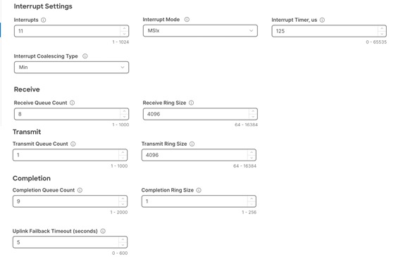
The adapter policy allows the administrator to declare the capabilities of the vNIC, such as the number of rings, ring sizes, and offload enablement and disablement. The transmit queues and receive queues defined in the default VMware adapter policy may not be sufficient as more SQL Server databases are consolidated which would generate a lot of VM management traffic on the FlashStack system.
Figure 19 shows the Adapter policy used for the vNICs 02-vDS0-A and 03-vDS0-3.
BIOS Policy
BIOS settings to be applied on the host will change based on the workload they run. The default BIOS settings promote power savings by reducing the operating speeds of processors and move the cores to deeper sleep states. These states need to be disabled for sustained high performance of database queries. For the server bios settings recommended for enterprise workloads are discussed in more detailed here:
For this solution, the following BIOS settings are used and validated. The rest of the settings were set to Platform Default.
| Category |
Setting |
Value Used |
| PCI |
SR-IOV Enabled |
Enabled |
| Processor |
Adjacent Cache Line Prefetcher Inter HyperThreading Technology Inter TurboBoost Tech LLC Prefetch Patrol Scrub Processor C1E Processor C3 Report Processor C6 Report P-STATE Coordination Power Performance Tuning XPT Prefetch |
Enabled Enabled Enabled Enabled Enabled Disabled Disabled Disabled HW-ALL OS Enabled |
Note: Before changing any bios setting in the production environments, the changes should be first tested and analyzed in the test environments.
FC SAN Configuration on Fabric Interconnects
Cisco UCS 6536 Fabric Interconnects allows us to configure the last four ports (33 to 36) as unified ports to carry the Fibre channel traffic. Since these unified ports on FI6536 are 100G ports, these need to be configured as 4x 32G break out ports when they are connected to MDS 6132T Fibre Channel switches.
For this validation, only the last port (port 36) is configured as unified port on each Fabric Interconnect. Table 8 lists more details on how the Unified Port on Fabric Interconnects 6536 are configured.
Table 8. FC SAN Unified Ports Configuration on FI 6536
| Fabric Interconnect |
Unified Port Number |
Break Out Option and Ports |
Connected to MDS |
VSAN ID |
| A |
Port 36 |
1x 100G to 4x 32G ( 36/1, 36/2, 36/3, 36/4) |
MDS-A (Ports 3,4,5,6) |
103 |
| B |
Port 36 |
1x 100G to 4x 32G ( 36/1, 36/2, 36/3, 36/4) |
MDS-B (Ports 3,4,5,6) |
104 |
Note: You can always increase the unified port count and connect them to Cisco MDS for additional storage bandwidth and High Availability (HA) purposes.
Figure 20 shows how to set Ports 36 as 4x 32G break out ports.
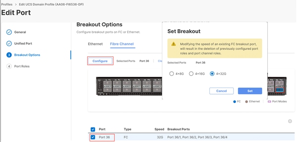
The four break out cables, which connect port 36 on each FI to MDS switch, will form a Fibre Channel Port Channel and will have aggregated bandwidth of 128G on MDS switches.
The following vHBAs are defined in a SAN connectivity policy for the Pure Storage connectivity of the ESXi host. The SAN connectivity policy is used in the Server profile template to derive the Server profile and the server profile is associated to a Cisco UCS X210c M7 blade:
● vHBA-A: This HBA will be connected to fabric A side of MDS switches and used for ESXi SAN boot traffic as well as database traffic.
● vHBA-B: This HBA will be connected to fabric A side of MDS switches and used for ESXi SAN boot traffic as well as database traffic.
Table 9 lists all the setting used for the above vHBAs.
| vHBA Name |
vHBA-A |
vHBA-B |
| vHBA Type |
Fc-initiator |
1x |
| Slot ID |
MLOM |
MLOM |
| PCI Link |
0 |
0 |
| Switch ID |
A |
B |
| PCI Order |
4 |
5 |
| Persistent Lun Binding |
Enabled |
Enabled |
| Fibre Channel Network (VSAN ID) |
103 |
104 |
| QoS |
Rate Limit=0 Class of Service=3 |
Rate Limit=0 Class of Service=3 |
| Fibre Channel Adapter Policy |
Default “VMware” Adapter policy with “IO Throttle” set to 1024 |
Default “VMware” Adapter policy with “IO Throttle” set to 1024 |
After using the LAN and SAN connectivity policies within a server profile template, four server profiles are instantiated and associated to four Cisco UCS X210c M7 blades.
Figure 21 shows the four derived server profiles and associated with the blades (slots 3 to 7).
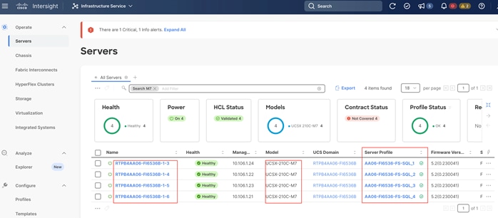
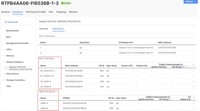
Figure 22 shows the vNIC and vHBA interfaces after successfully associating a server profile to a Cisco UCS X210c M7 blade server.
In this solution, the Cisco UCS X210c M7 blade servers are configured to boot from the Pure Storage volumes. For the ESXi hosts to establish connections to the Pure Storage over Fibre Channel, required WWN names of the Pure Storage FlashArray need to be configured in the Boot policy. Gather the WWN names of scsi-fc ports of Pure Storage array by executing “pureport list” command on the Pure Storage SSH terminal.
Table 10 lists the information gathered from Pure Storage FlashArray for configuring the Boot Policy. Two target ports are used from each side of the Fibre Channel switching fabric.
Table 10. WWN Names of Pure Storage FlashArray//XL170
| Controller |
Port Name |
WWN Name |
| CT0 |
CT0.FC4 |
52:4A:93:7D:FE:FB:53:04 |
| CT0 |
CT0.FC5 |
52:4A:93:7D:FE:FB:53:05 |
| CT1 |
CT0.FC4 |
52:4A:93:7D:FE:FB:53:14 |
| CT1 |
CT0.FC5 |
52:4A:93:7D:FE:FB:53:15 |
Once this information is gathered from the controller, a boot policy to boot from FC SAN is configured as shown in Figure 23.
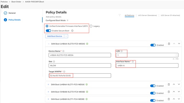
As highlighted, select the UEFI boot mode, set the slot as MLOM, LUN Number should match with the LUN ID you mention when you create the boot volume in Pure Storage for the corresponding ESXi host. And Interface Name should match with the vHBA name you provided in the VSAN connectivity policy. Refer to the SAN Connectivity Policy section.
After the successful server profiles association by using the above boot policy and with right zoning configuration on the Cisco MDS switches is in place, the Cisco UCS X210c M7 blade server should list four paths to its boot volume while booting into the ESXi as shown in Figure 24.
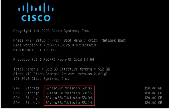
VMware vSphere ESXi Host Configuration
This section describes the VMWare ESXi host-specific configurations to be implemented on each ESXi host.
Update VIC Drivers
It is recommended to use the latest VIC drivers for the specific vSphere ESXi hypervisor. For the most recent VIC driver versions, refer to: Cisco UCS Hardware & Software Interoperability Matrix. At the time of testing of this solution, the following are the versions of the VIC drivers that were used from the Cisco custom image for VMware vSphere 8.0U1.
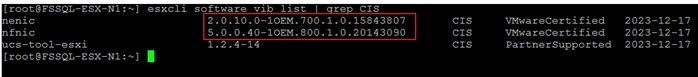
You can always check the VMware site for any nenic and nfnic drivers for the corresponding vSphere ESXi version. Figure 26 shows upgrading the nfnic drivers from 5.0.0.40 to 5.0.043. Reboot the server for the driver upgrade to take effect.
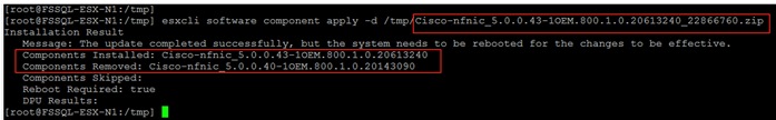
ESXi has been heavily tuned for driving high I/O throughput efficiently by utilizing fewer CPU cycles and conserving power. Hence the Power setting on the ESXi host is set to “Balanced.” However, for critical database deployments, it is recommended to set the power setting to “High Performance.” Selecting “High Performance” causes the physical cores to run at higher frequencies and thereby it will have a positive impact on the database performance.
ESXi Host Networking Configuration
This section provides information about the ESXi host network configuration used for this FlashStack system. The ESXi host should discover four ethernet network adapters. The first two adapters are used for creating a standard switch (vSwitch0) which is used for management traffic while the last two adapters are used for creating Distributed Switch (vDS0) for the rest of the traffic. Table 11 lists the network configuration used for this solution.
Table 11. ESXi Host Network Configuration
| Switch Name |
Details |
| vSwitch0 |
Purpose: For managing and accessing ESXi hosts and for Out Of Band access ESXi Physical Adapters: vmnic0 (active) and vmnic1 (standby) VLANs: 1060, 1061 MTU: 1500 PortGroups:
● Management Network (VLAN: 1061): For managing and accessing ESXi hosts
Physical Adapter Configuration: vmnic0(active) and vmnic1 (active)
vmkernel: vmk0
● OOB-MGMT (VLAN: 1060): For Out of Band management traffic for managing ESXi hosts.
Physical Adapter Configuration: vmnic0(active) and vmnic1 (active) |
| vDS1 |
Purpose: For SQL VM management traffic and vMotion ESXi Physical Adapters: vmnic2 (UPLINK 1) and vmnic3 (UPLINK 2) VLANs: 1061, 1062 and 3000 MTU: 9000 PortGroups:
VM-MGMT1 (VLAN: 1061): For SQL VM management traffic
Physical Adapter Configuration: vmnic2(active ) and vmnic3 (active)
vMotion (VLAN: 3000): For vMotion traffic
Physical Adapter Configuration: vmnic2(standby) and vmnic3 (active)
vmkernel: vmk1, with MTU 9000 |
Figure 27 shows the ESXi network configuration used for this solution.
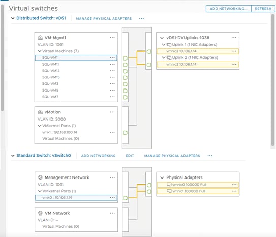
Preserving TPM Encryption Key
Typically hosts in FlashStack Datacenter are booted from SAN configured. Cisco UCS supports stateless compute where a server profile can be moved from one blade or compute node to another seamlessly. When a server profile is moved from one blade to another blade server with the following conditions, the ESXi host runs into PSOD and ESXi will fail to boot.
● TPM present in the node (Cisco UCS M5 and Cisco UCS M6 family servers)
● Host installed with ESXi 7.0 U2 or above.
● Boot mode is uEFI and Secure boot option is enabled
The error message “Unable to restore the system configuration. A security violation was detected: https://via.vmw.com/security-violation” displays on the server console.
For more details about this known issue, go to: https://kb.vmware.com/s/article/81446
The cause for this error is that the server is not able to decrypt the information as the TPM encryption key is missing. The encryption key is stored on the server’s ROM and did not get carried forward along with the service profile.
Until it is fixed in next Cisco UCS release, follow this workaround to boot new server successfully when you a service is migrated from one server to other:
Procedure 1. Preserving TPM Key
Step 1. After ESXi installed, ssh into the ESXi server. Execute the following command to list the recovery keys. Copy the Encryption key and store it in a safe location. Repeat this step for all ESXi servers.
esxcli system settings encryption recovery list
Step 2. After the service profile is associated to a new server and while the ESXi server is booting, stop the ESXi boot sequence by pressing Shift+O.
Step 3. At the boot command prompt, enter the recovery using following boot option:
encryptionRecoveryKey=recovery_key
Step 4. Press Enter to continue to boot process.
Note: Immediately after ESXi installation, ensure to take backup of the TPM encryptions key for each ESXi host and store them in a safe location.
VMware vSphere Virtual Volumes (vVols) Provisioning
vVols is used in this solution for storing SQL Server virtual machine virtual disks, including OS disk, and virtual disks that store SQL Server database data and T-Log files. Complete the following procedures to be able to provision the vVols.
The Pure Storage Plugin for the vSphere Web client needs to be installed to provision the vVols. For vSphere 8.0 or higher, VMware no longer supports local plugins to be installed in vCenter . it is required to use storage plugin remote 5.x to manage the VMware infrastructure. The Pure Storage VMware Appliance was released to support deployments of Pure Storage integrations such as the Remote Plugin for the vSphere Client and the VM Analytics Collector. Refer to the following links for more details on the storge plugin version and dependency details: https://support.purestorage.com/Solutions/VMware_Platform_Guide/Release_Notes_for_VMware_Solutions/Release_Notes%3A_Pure_Storage_Plugin_for_the_vSphere_Client
Pure Storage VMware Appliance installation and Registering vSphere
For detailed steps for installing the Pure Storage VMware appliance installation, see: https://support.purestorage.com/Solutions/VMware_Platform_Guide/User_Guides_for_VMware_Solutions/Using_the_Pure_Storage_Plugin_for_the_vSphere_Client/vSphere_Plugin_User_Guide%3A_Installing_and_Removing_the_Remote_vSphere_5.x_Plugin_with_the_Pure_Storage_VMware_Appliance#Deploying_the_Pure_Storage_VMware_Appliance
Once the Storage plugin VMware appliance is deployed, the appliance can be upgraded to the latest release by completing the following procedure.
Procedure 1. Upgrade Pure Storage VMware Appliance
This is the process to upgrade when using either the Remote Plugin or VMware Appliance.
Step 1. Check the current software version by running the following command.
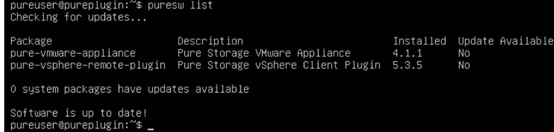
Step 2. If the new versions/packages are available, upgrade the individual components by running the following command.
puresw upgrade start pure-vsphere-remote-plugin or pure-vmware-appliance
Procedure 2. Setting Pure Plugin attributes
Verify if the appliance is using the correct domain and DNS servers. If not, set the correct ones using the following procedure.
Step 1. Run “puredns list” to view the current DNS settings and if required update the attributes as shown below.
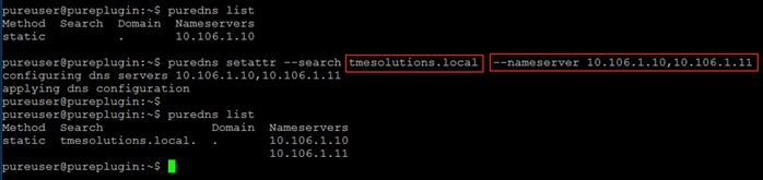
Procedure 3. Register vCenter
Step 1. Use the “pureplugin register” command and positional argument to register the remote plugin's extensions with the vCenter server.
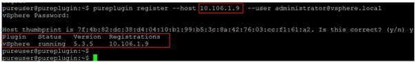
A successful registration will appear within vCenter.
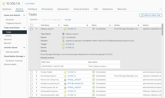
Step 2. After successful vCenter registration, Launch the Pure Storage Plugin as shown below.
Procedure 4. Add Storage Array
Step 1. Using the storage plugin, add the Pure Storage FlashArray in the vCenter as shown below. Optionally, you can create a new user in Pure Storage purity and use it for adding the storage array as shown below.
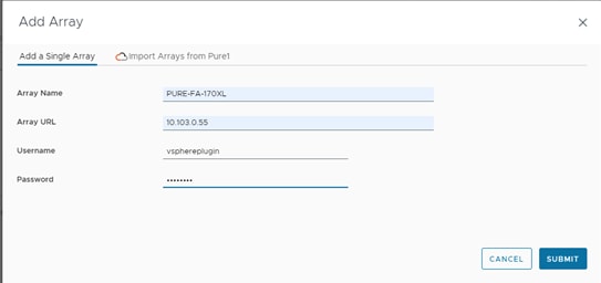
Procedure 5. VASA registration
The vSphere Plugin allows you to register Storage Providers the ability to register a FlashArray's VASA Providers that has been Added to the FlashArray list.
Step 1. After adding/registering the FlashArray in the plugin, navigate to the main Plugin Page, select the FlashArray and then click on "Register Storage Provider". The recommended practice is to have a local FlashArray Array Admin user to register the storage providers with. In the example below, there is a local array admin named "vvols-user" that the Storage Providers will be registered.
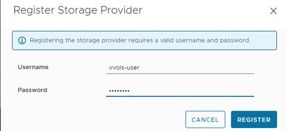
Step 2. Once the Storage Provider is successfully registered, navigate to the vCenter Server page, then Config and the Storage Providers tab. Confirm that the storage providers are online and healthy as shown below.
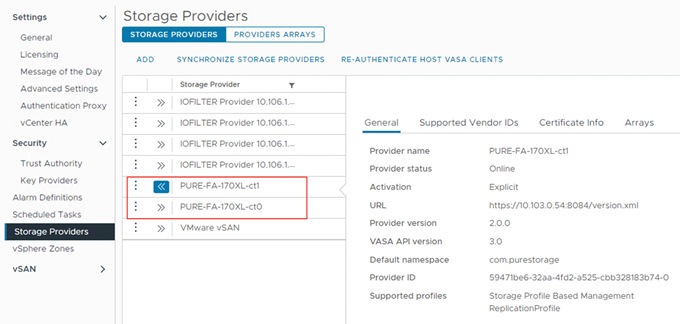
Procedure 6. Provision vVol
Once the Storage Providers are registered the vVol Datastore can be created and mounted using the vSphere Plugin in ESXi Cluster. Right click on vCenter Cluster, select Pure Storage plugin, and select Create Datastore option.
Step 1. On the Create Datastore window, choose to create a vVol FlashArray Storage Container (vVol Datastore) and click Next.
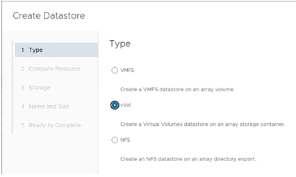
Step 2. Select the vSphere cluster and click Next.
Step 3. Select the FlashArray and click Next.
Step 4. Provide a name to the vVol and click Next. Review the settings once and click Finish.
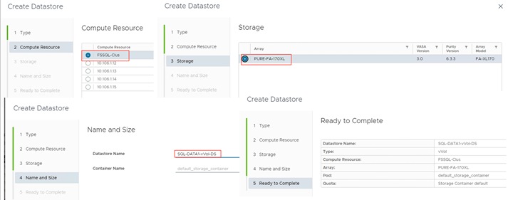
Note: The default_storage_container is the default container name created and populated by default.
Step 5. Verify that all the ESXi hosts are connected to the vVolume as shown below.
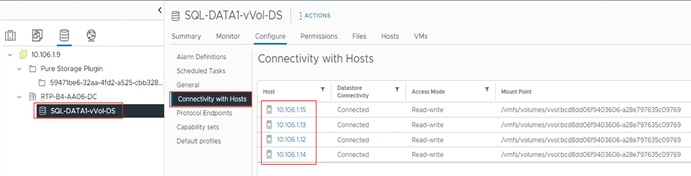
Procedure 7. Update the Default Queue Depth Setting of the VIC Adapter
By default, the Queue Depth of the adapter at the ESXi level is set to 32 only. In a virtual environment with good consolidation ratios hosting IO sensitive workloads like databases, the default queue depth will soon get exhausted leading to the higher latencies and lower IOPS. It is recommended to set the queue depth to a higher value for better IOPS and latency.
Step 1. Before changing at the Host level, first ensure that the “IO Throttle” count is set to 1024 at the VIC adapter level as recommended in the table “vHBA Configuration.” The following figure shows the IO Throttle set to 1024 using FC adapter policy.
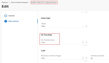
Step 2. The following screenshot shows how to change the adapter queue depth from default 32 to 256. After updating, reboot server for the change to take effect.
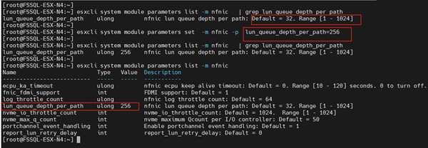
Note: Ensure to update the queue depth value on all the ESXi hosts. Also, it is recommended to increase the Queue Depth in small chunks (start with 64), test and analyze the system with the given workload and decide queue depth needs to be increased further.
Procedure 8. ESXi Native Multipath Configuration and Adjusting IO Limits
ESXi Round Robin PSP (Path Selection Policy) uses a round-robin algorithm to balance the load across all active storage paths. A path is selected and used until a specific quantity of data has been transferred. After that quantity is reached, the PSP selects the next path in the list. The quantity at which a path change triggered is known as the limit. Round Robin defaults to an IOPS limit with a value 1000. In this default case, a new path is used after 1000 I/O operations are issued.
Step 1. For high-end ESXi clusters driving thousands of IOPS, changing the IOPS limit per active path will result in a slight performance increase as well as quicker path failover (if it is needed). The IOPS limits can be changed for the required datastores (where SQL database files are stored) by executing the following command. Replace XXXX with first few characters of your naa IDs:
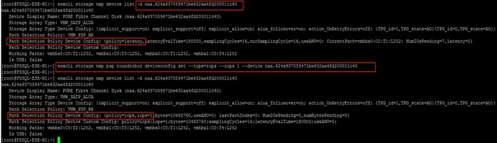
Step 2. Ensure to update the IO limit to 1 on all the ESXi hosts.
The following figure shows the storage path utilizations for the four ESXi hosts with IOPS limits set to 1. As shown, each host has four active paths to the storage and all the paths are equally optimal.
Step 3. Run the following command from the Pure CLI session to view the below details.
purehost monitor --balance --interval 30
For more information on changing IOPS limits, go to https://kb.vmware.com/s/article/2053145
SQL Server Virtual Machine Configuration
This section describes the best practices and recommendations to create and deploy SQL Server Virtual Machines on the FlashStack system.
Memory Reservation
SQL Server database transactions are usually CPU and memory intensive. In heavily OLTP database systems, you should reserve all the memory allocated to the SQL Server virtual machines as shown in the following figure. This approach helps ensure that the memory assigned to the SQL Server virtual machines is committed, and it eliminates the possibility that ballooning and swapping will occur.
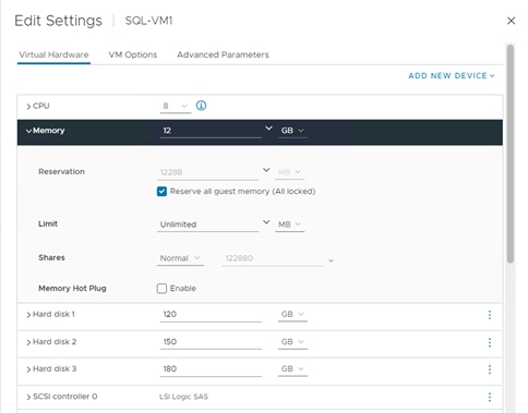
The network adapter of type VMXNET3 should be used for any SQL Server virtual machine. VMXNET 3 is the latest generation of para virtualized NICs designed for performance. It offers several advanced features, including multiple-queue support, receive-side scaling, IPv4/IPv6 offloads, and message-signaled interrupt (MSI) and MSI-X interrupt delivery.
Paravirtual SCSI Adapters for SQL Server Virtual Machines
For virtual machines with high disk IO requirements, it is recommended to use Paravirtual SCSI (PVSCSI) adapters. PVSCSI controller is a virtualization aware, high-performance SCSI adapter that allows the lowest possible latency and highest throughput with the lowest CPU overhead. It also has higher queue depth limits compared to other legacy controllers. Legacy controllers (LSI Logic SAS, LSI Logic Parallel and so on) can cause bottlenecks and impact database performance; therefore, it is not recommended for IO intensive database applications such as SQL server databases.
PVSCSI adapters have a default Queue Depth limit of 64 per device and 256 per adapter. For high capacity with high IO requirements, it is recommended to use multiple database files stored on multiple virtual disks and have those virtual disks distributed across multiple SCSI controller adapters rather than assigning all of the virtual disks to a single SCSI controller. This ensures that the guest VM will access multiple virtual SCSI controllers (four SCSI controllers’ maximum per guest VM), which in turn results in greater concurrency by utilizing the multiple queues available for the four SCSI Adapters.
Table 12 lists the sample SQL VM disk layout used for this solution validation. More virtual disks can be added (up to 64) to each PVSCSI controller based on io requirement.
Table 12. SQL VM Virtual Disks Layout for 100GB database
| SCSI Controller |
Controller Type |
Disk Purpose |
Disk Size(GB) |
Datastore (vVol) and storage Policy |
| SCSI Controller 0 |
Para Virtual (PVSCSI) or LSI Logic SAS |
OS + SQL Binaries |
120 |
vVol (SQL-DATA1-vVOL-DS) |
| SCSI Controller 1 |
Para Virtual (PVSCSI) |
SQL data Disk (for storing user DB and Tempdb Data files) |
150 |
vVol (SQL-DATA1-vVOL-DS) |
| SCSI Controller 2 |
Para Virtual (PVSCSI) |
SQL Log Disk (for storing user DB and Tempdb T-Log files) |
180 |
vVol (SQL-DATA1-vVOL-DS) |
| SCSI Controller 3 (optional) |
Para Virtual (PVSCSI) |
For storing SQL DB backup files |
200 |
vVol (SQL-DATA1-vVOL-DS) |
Install Guest Operating System
This section provides the details about the configuration recommendations for Windows Guest Operating System for hosting SQL Server databases.
For a detailed step-by-step process to install Windows Server 2022 Guest Operating System in the virtual machine, please refer to the VMware documentation.
Note: When the Windows Guest Operating System is installed in the virtual machine, it is highly recommended to install the latest VMware tools as explained here.
The default power policy option in Windows Server is “Balanced.” This configuration allows Windows Server OS to save power consumption by periodically throttling power to the CPU and turning off devices such as the network cards in the guest when Windows Server determines that they are idle or unused. This capability is inefficient for critical SQL Server workloads due to the latency and disruption introduced by the act of powering-off and powering-on CPUs and devices. For SQL Server database deployments, it is recommended to set the power management option to “High Performance” for optimal database performance as shown in Figure 29.
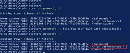
Increase PVSCSI Adapter Queue Depth Inside SQL Virtual Machines
Some of the Microsoft SQL Server databases will be relatively large and tend to issue a lot of simultaneous IOs resulting in insufficient device queue depth settings to sustain the heavy IOs. For such database virtual machines, It is recommended to change the default queue depth setting to a higher value (up to 254 per device and 1024 for PVSCSI Adapter) as suggested in this VMware KB article: https://kb.vmware.com/s/article/2053145. Execute the following command on Windows Guest OS using PowerShell and reboot the guest VM for the changes to take effect:
REG ADD HKLM\SYSTEM\CurrentControlSet\services\pvscsi\Parameters\Device /v DriverParameter /t REG_SZ /d "RequestRingPages=32,MaxQueueDepth=254"
NTFS file system with 64K allocation unit size is used for this solution for formatting the disks that are used for storing SQL database data and transaction log files.
Add Windows Guest to Active Directory Domain
It is recommended to change the default Windows Guest VM name and join it to the domain before proceeding with SQL Server installation in the guest virtual machine. For detailed instructions about how to change the Guest name and join the Guest, click here.
Using the server manager, enable the Remote Desktop feature to manage the Guest VM remotely and make sure to enable port 1433 port for accessing SQL Server by the clients or other applications.
Install SQL Server and Configuration Recommendations
There are many recommendations and best practices guides available for most of SQL Server settings. But the relevance of these recommendations may vary from one database deployment to another. It is recommended to thoroughly test and validate the critical settings and determine whether or not to implement the specific database environment. The following sections describe some of the key aspects of the SQL Server installation and configurations, which have been used and tested on the FlashStack system. The rest of the SQL Server settings are kept at default and used for performance testing.
Procedure 1. SQL Server Installation and Configuration
This section provides a high-level installation process. For the detailed step-by-step installation for SQL Server 2022 on a Windows Operating system, refer to the Microsoft document: Install SQL Server from the Installation Wizard (Setup).
Step 1. From the Server Configuration window of SQL Server installation, make sure that the instant file initialization is enabled by enabling the checkbox as shown below. This makes sure the SQL server data files are instantly initialized avoiding zeroing operations.
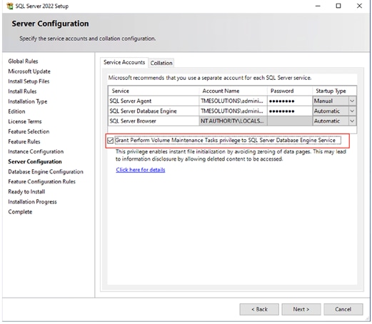
Step 2. In the Database Engine Configuration window under the TempDB tab, make sure the number of TempDB data files are equal to 8 when the vCPUs or logical processors of the SQL VM is less than or equal to 8. If the number of logical processors is more than 8, start with 8 data files and try to add data files in the multiple of 4 when the contention is noticed on the TempDB resources. The following diagram shows that there are 8 TempDB files chosen for a SQL virtual machine which has 8 vCPUs. Also, as a best practice, make sure the TempDB data and log files are two different volumes.
Step 3. Make sure to add a SQL Server service account is added to “Lock Pages in Memory” policy using the Windows Group Policy editor. Granting the Lock pages in memory user the right to the SQL Server service account prevents SQL Server buffer pool pages from paging out by the Windows Server.
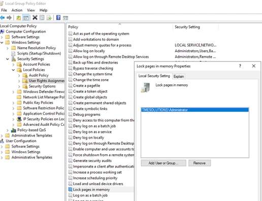
Step 4. A domain account is used as a SQL Server service account which is not a member of the local administrator group, then add SQL Server service account to the “Perform volume maintenance tasks” policy using the Local Security Policy editor.
Step 5. The following specific SQL Server settings were used for this validation and left the rest of the settings as default.
alter server configuration set softNUMA off
go
EXEC sys.sp_configure N'show advanced options', 1
RECONFIGURE WITH OVERRIDE
sp_configure N'max degree of parallelism' ,0
RECONFIGURE WITH OVERRIDE
EXEC sys.sp_configure N'max server memory (MB)', N'9216' -- nearly 80% of 12GB
GO
RECONFIGURE WITH OVERRIDE
GO
--- Ensure the following DMVs report the right number of schedulers and memory nodes
select count(*) from sys.dm_os_schedulers where status='VISIBLE ONLINE'
select * from sys.dm_os_nodes
select * from sys.dm_os_memory_nodes
Intel Quick Assist Technology Drivers Installation and Configuration
This section provides the configuration steps required for leveraging Intel QAT feature for offloading compute intensive tasks such as compression to the integrated Intel QAT hardware Accelerators.
Note that not all the Intel CPU SKUs support the QAT accelerators. Supported Intel CPU SKUs need to be installed on the UCS X210c M7 blade to detect and leverage them in the solution. Refer the following link for identifying QAT supported Intel CPUs : https://www.intel.com/content/www/us/en/support/articles/000095464/technologies/intel-quickassist-technology-intel-qat.html
Procedure 1. QAT Drivers installation in ESXI
Step 1. Download latest Intel QAT drivers from the below link and copy it to the ESXi host. https://www.intel.com/content/www/us/en/download/761741/intel-quickassist-technology-driver-for-vmware-esxi-hardware-version-2-0.html
The release notes for the latest QAT drivers, is available here :
Step 2. Install QAT drivers inside the ESXi host as shown below. Reboot the ESXi host and verify the QAT drivers are installed once the server is up. As shown below, after the server is back online, four QAT physical accelerators are shown in the host.
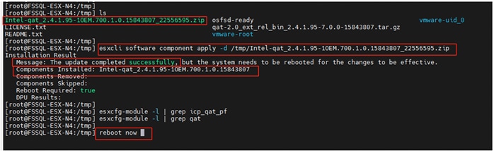
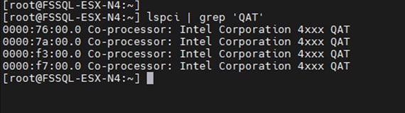
Step 3. Login to each ESXi host, navigate to Configure -> PCI Devices, for each Physical QAT accelerator device, enable the SRIOV and provide the number of virtual functions to be available on that physical accelerator as shown below.
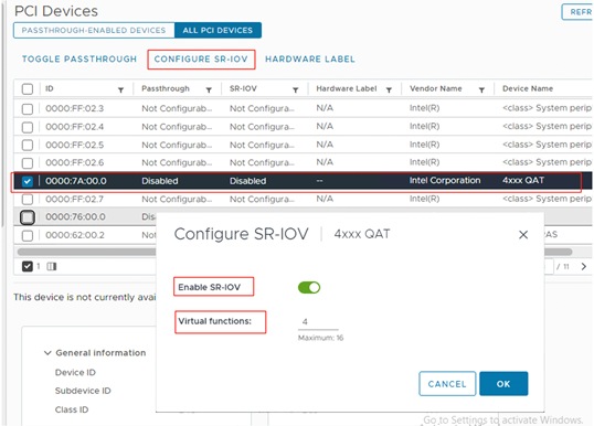
The following figure shows 16 Virtual Functions (VFs) of QAT accelerators in a ESXi host after configuring 4 VFs on each physical accelerator device.
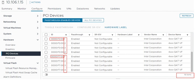
Step 4. Once the required QAT VFs are defined in the ESXi host, they can be allocated to the virtual machines by mapping them to a PCI device as shown below. For the best QAT performance, allocate one VFs from each physical QAT device for a given virtual machine instead of allocating all VFs from the same physical QAT device.
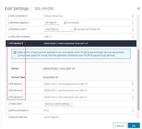
Note: The virtual machine which has QAT VFs configured, cannot be migrated to a different ESXi host automatically in case of ESXi host failure. For a planned down time, it should be first migrated manually (first remove the QAT VFs from the VM) to a different host and then go for a planned downtime of the host. For the unplanned downtime, the VM will not be accessible until the ESXi host comes online. Therefore QAT may not be recommended for the deployment where availability of the VM is the critical requirement.
Procedure 2. QAT Drivers installation in Windows Guest
Step 1. After the VFs are allocated to the VM as PCI devices, they will not be discovered until the required QAT drivers are installed on the guest. The following figure shows four QAT devices before and after QAT installation drivers within the Guest VM.
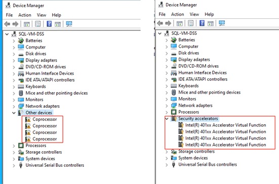
Step 2. Download the latest QAT drivers for Windows guest Operating system from the below link and install the drivers by launching the QAT2.0.W.2.0.5-0014\QuickAssist\Setup\QatSetup.exe file.
Procedure 3. SQL Server configuration for QAT
Step 1. Once QAT accelerators are detected in the Guest OS, the next step is to enable and configure SQL Server to leverage the QAT accelerators. Execute the following T-SQL script on the SQL Server instance for taking advantage of QAT accelerators.
Sp_configure ‘show advanced options’,1
reconfigure with override
go
sp_configure ‘hardware offload enabled’, 1
reconfigure with override
--restart SQL Server
ALTER SERVER CONFIGURATION SET HARDWARE_OFFLOAD = ON (ACCELERATOR = QAT);
go
--restart SQL Server
select accelerator,accelerator_desc,mode_desc,mode_reason_desc,accelerator_library_version,accelerator_library_version FROM sys.dm_server_accelerator_status;
go
EXEC xp_ReadErrorLog 0, 1, N'QuickAssist Technology'
Go
Step 2. The last two commands in the above T-SQL commands will confirm if SQL Server is able to detect the drivers in Hardware mode and be able to use them for offloading backup compression;
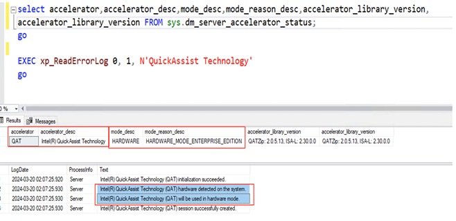
Step 3. Use the following last two sample commands can be used for taking FULL database backup with SQL Native compression and compression offloaded to QAT.
--- BACKUP Compression using native SQL Compression
BACKUP DATABASE [tpch1000g] TO
DISK = N'P:\backup\TPCH1000G_FULL_Native_1.Bak',
DISK = N'Q:\backup\TPCH1000G_FULL_Native_2.Bak',
DISK = N'R:\backup\TPCH1000G_FULL_Native_3.Bak',
DISK = N'S:\backup\TPCH1000G_FULL_Native_4.Bak'
WITH NOFORMAT, NOINIT, NAME = N'tpch1000g-Full Database Backup',
SKIP, NOREWIND, NOUNLOAD, COMPRESSION(ALGORITHM=MS_XPRESS) ,STATS = 10
GO
-- BACKUP Compression using Intel QAT HW accelerator
BACKUP DATABASE [tpch1000g] TO
DISK = N'P:\backup\TPCH1000G_FULL_QAT_1.Bak',
DISK = N'Q:\backup\TPCH1000G_FUL_LQAT_2.Bak',
DISK = N'R:\backup\TPCH1000G_FULL_QAT_3.Bak',
DISK = N'S:\backup\TPCH1000G_FULL_QAT_4.Bak'
WITH NOFORMAT, NOINIT, NAME = N'tpch1000g-Full Database Backup',
SKIP, NOREWIND, NOUNLOAD, COMPRESSION(ALGORITHM=QAT_DEFLATE) ,STATS = 10
GO
Cloud Block Store Deployment on Azure Cloud
In this solution, Cloud Block Storage Asynchronous feature is used for replicating the snapshots from on-prem Pure Storage FlashArray//Xl170 to CBS hosted in Azure for hybrid-cloud Disaster Recovery (DR) use case. The data between the two sites is copied over a secured site-to-site VPN(Virtual Private Network) created between Azure Cloud and on-prem datacenter. For detailed steps on configuring Azure site-to-site VPN, refer to the link. https://learn.microsoft.com/en-us/azure/vpn-gateway/tutorial-site-to-site-portal
Once the VPN is established between the two sites, ensure the following prerequisites were followed and implemented before deploying CBS on Azure Cloud. Go to this link for CBS prerequisites: https://support.purestorage.com/Pure_Cloud_Block_Store/Pure_Cloud_Block_Store_on_Azure_Implementation_Guide/Cloud_Block_Store_on_Azure_Prerequisites
Deploy CBS On Azure Cloud
To deploying CBS on Azure Cloud, go to: https://support.purestorage.com/Pure_Cloud_Block_Store/Pure_Cloud_Block_Store_on_Azure_Implementation_Guide/Deploy_using_Azure_Portal
Figure 30 shows the CBS deployed in Azure Cloud for this CVD validation.
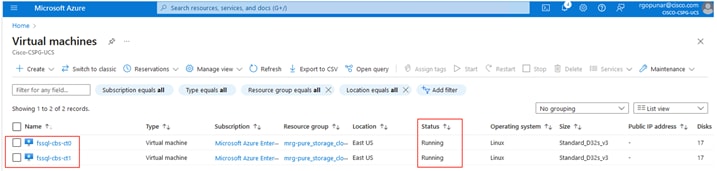
Figure 31 shows accessing CBS using its floating azure private IP address (10.0.0.3) from on-prem datacenter network.
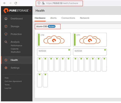
Once the CBS management and replication network IP addresses are reachable from on-prem datacenter, proceed with replication configuration between the two arrays which will be described in chapter System Validation and Testing.
This chapter contains the following:
● IO Performance Characterization using DiskSpd Tool
● 8K Random Read/Write IOPS Test
● Sequential Read/Write Bandwidth Test
● Performance Tests and Results for OLTP and DSS Workloads
● OLTP Database Performance Scalability Across ESXi Cluster
● DSS Performance Tests and Results
● Intel QAT Accelerator for Database Backup Performance Improvement
● Pure Storage Snapshots for SQL Server Database
● Cloud Block Storage (CBS) Asynchronous Replication for Disaster Recovery
This chapter provides a high-level summary of the performance testing and validation results for the FlashStack solution. The following list provides various performance tests conducted on the solution:
● IO calibration test using Microsoft DISKSPD tool to demonstrate the IO capacity of the Pure Storage FlashArray//XL AFF XL170 storage array (single pair of Controllers); The tests were conducted with various read write ratios and different block sizes to simulate the real time database workloads.
● Demonstrate Microsoft SQL Server OLTP database performance scalability for both scale-up and scale-out scenarios using single node ESXi (scale-up) and a four node ESXi cluster (scale-out) created using Cisco UCS X210c M7 compute nodes; HammerDB test tool is used to create and generate OLTP TPC-C like workload.
● Demonstrate Microsoft SQL Server DSS database performance with 1TB dataset hosted on a single Cisco UCS X210c M7 ESXi nodes; HammerDB test tool is used to create and generate OLAP TPC-H like workload.
● Demonstrate the benefits of using Intel Integrated Accelerators of latest Intel 4th or 5th Generation CPUs for SQL Server database backup/restore compression.
● Demonstrate Cloud Block Storage (CBS) for replicating data change from On-Prem premises to Azure Cloud for Data replication and Disaster Recovery use cases.
Note: This FlashStack configuration was successfully verified by performing multiple failure tests to determine database persistence and performance
IO Performance Characterization using DiskSpd Tool
Before deploying and running actual database workload tests, it is important to validate the system with synthetic tools to ensure that the system is optimally configured.
DISKSPD is an I/O generating, command-line tool for micro-benchmarking. It allows us to customize and create your own synthetic workloads and test your application before deployment.
We run various DISKSPD tests for measuring IOPS, Latency and Throughput performance of this solution by changing block size parameter and read/write ratio. The following screenshots show some of the test results that were executed on the system.
8K Random Read/Write IOPS Test
Figure 32 shows results for the random read/write test with 8KB block size representing transactional (OLTP) workload. For this test, sixteen Windows Guest VMs were created and spread across 4-node ESXi cluster (4 VMs per node) and the DISKSPD commands were executed on each VM.
For the 8K random 100% read test, the following command was executed on the sixteen VMs spread across the 4-node ESXi cluster. As shown, more than one million IOPS were delivered under 0.02ms (20 microseconds) read latency.
.\DiskSpd.exe -c15G -d1200 -r -w0 -t8 -o2 -b8K -h -L E:\testfile.data
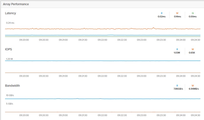
Figure 33 shows the test results for 70:30 read/write random IO test with 8KB block size. As shown, nearly 940K IOPS were delivered in 70:30 read/write ratio under 0.10ms write latency. For the 8K random 70-30% read/write ratio, the following command was executed on all the sixteen VMs.
.\DiskSpd.exe -c15G -d1200 -r -w30 -t8 -o2 -b8K -h -L E:\testfile.data
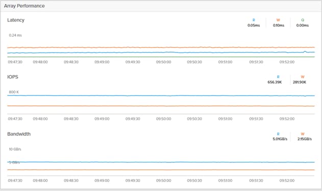
Figure 34 shows the test results for 100% write random IO test with 8KB block size. As shown, around 780K IOPS write IOPS were delivered under 0.12ms write latency. For the 8K random 100% write, the following command was executed on all the sixteen VMs.
.\DiskSpd.exe -c15G -d1200 -r -w100 -t8 -o2 -b8K -h -L E:\testfile.data
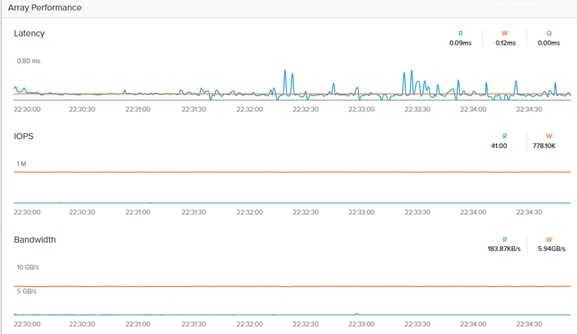
Sequential Read/Write Bandwidth Test
The intention of this test is to demonstrate the bandwidth delivered by a single guest VM hosted on the given FlashStack system; This test is carried out with 512K IO size from a single Windows Guest VM. For this test, the below command was executed on the Single Windows guest VM.
.\DiskSpd.exe -c15G -d1200 -si -w0 -t8 -o2 -b512K -h -L E:\testfile.data
In the current FlashStack system only 4x 32Gbps FC ports (two from each storage controller) are leveraged; As shown in Figure 35, single windows guest VM could deliver nearly 12GB/s read bandwidth with just four 32Gbps ports being configured to use.
Figure 36 shows the test results for 100% sequential write IO test with 512K block size. As shown, around 10.4GB/s write bandwidth is achieved under 0.20ms write latency with the current configuration. For the 512K 100% sequential write test, the following command was executed on all the sixteen VMs.
.\DiskSpd.exe -c15G -d1200 -si -w100 -t8 -o2 -b512K -h -L E:\testfile.data
This clearly demonstrates the bandwidth capabilities of Pure FlashArray//XL170 storage array. The bandwidth can be further improved by upgrading from 32Gb FC used in testing to 64Gb FC, and by connecting more FC ports of the storage array in the system.
It is important to note that this is not a benchmarking exercise and the numbers presented are not the peak numbers where there is hardware resource saturation. The above performance numbers are specific to this Virtualized ESXi FlashStack system with specific connections/ports being configured to use.
Performance Tests and Results for OLTP and DSS Workloads
This FlashStack system is tested and validated with Microsoft SQL Server 2022 databases for OLTP (Online Transaction Processing) workloads. The objective of these tests is to demonstrate how performance scales as more SQL Server virtual machines are added with in a single ESXi host (one Cisco UCS X210c M7) and a 4-node ESXi cluster (four Cisco UCS X210c M7s).
The following database performance tests were conducted to demonstrate the performance scalability.
● Demonstrate Microsoft SQL Server OLTP database performance scalability within a single ESXi host representing scale-up performance scenario.
● Demonstrate Microsoft SQL Server OLTP database performance scalability across 4-node ESXi cluster representing scale-out performance scenario.
Table 13 lists SQL Server virtual machine configuration and database schema details used for these database performance scalability tests.
Table 13. SQL Server Virtual Machine Configuration for Scalability Tests
| Component |
Details |
| VM configuration |
12 vCPUs, 12GB Memory |
| Storage |
1x 150GB volume for storing data files of tempdb and 100G test database. 1x 180GB volume for storing transaction Log (T-Log) files of tempdb and 100G test database. |
| Database |
Microsoft SQL Server 2022 (Enterprise Eval Edition) |
| Guest OS |
Windows Server 2022 Standard Edition |
| Workload Details SQL VM |
Database Size: 100GB Test Tool : HammerDB Metrics Monitored and Collected: IOPS and Latency at Guest level Transactions Per Minutes reported by HammerDB. ESXTOP for ESXi host CP utilization Pure System Manager |
HammerDB is the leading benchmarking and load testing software for the world’s most popular databases like Microsoft SQL Server. It implements a fair usage of TPC specifications for benchmarking the database workloads such as Online Transactional (OLTP) and Decision Support System(DSS). TPC is an industry body most widely recognized for defining benchmarks. The same HammerDB tool is used for testing both OLTP and DSS workloads using Microsoft SQL Server databases hosted on the FlashStack system.
For these performance tests, a separate compute node is used to create and run multiple HammerDB instances of HammerDB to stress the SQL Server guest VMs hosted on the FlashStack system. A sample 100GB database was loaded and used for the performance tests.
OLTP Database Performance Scalability with in Single X210c M7 ESXi Host
This test focuses on how a single Cisco UCS X210c M7 ESXi host can respond as more SQL Server workload virtual machines are loaded on the same host. As shown in Figure 37, a single SQL Server virtual machine delivered about 9087 Transactions Per Second (TPS) driving about 11,000 IOPS and utilizing 9% CPU on the ESXi host. As more SQL Server virtual machines were added to the same ESXi host (scaled to up to eight virtual machines), the TPS, IOPS and ESXi host CPU usage scaled near linearly because no bottlenecks were discovered within the FlashStack System.
Note: The IO latencies were maintained within sub-millisecond during the above tests.
OLTP Database Performance Scalability Across ESXi Cluster
The objective of this test is to demonstrate the database performance scalability when multiple SQL Server virtual machines are deployed across a four-node ESXi cluster.
This test started with four virtual machines spread across the cluster and then scaled by group of four virtual machines up to 16 virtual machines (4 VMs per host).
As shown in Figure 38, four virtual machines (1 VM per host) collectively delivered about 38,000 Transactions Per Second (TPS) driving about 44,000 IOPS and utilizing 9.4% CPU on each ESXi host in the cluster. As more virtual machines were added to the ESXi cluster, TPS, IOPS and the CPU utilization of the cluster also scaled near linearly because no bottlenecks were discovered with in the FlashStack system.
Note that the IO latencies were maintained within the sub-milliseconds during the above tests. For instance, the following screenshot, captured from Pure Storage FlashArray UI, shows the IO metrics for the 16 VM test. As shown, read and write IO latencies stayed under 360 microseconds during the test.
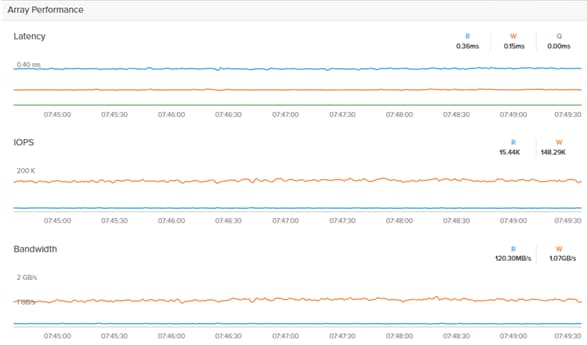
These OLTP performance tests demonstrates that the underlying FlashStack system, built with Cisco UCS X210c M7 blades, 5th Gen FIs and Pure FlashStorage//XL170 storage array, capable of delivering high consistent performance meeting the expectations of latency critical database workloads with varying IO sizes.
DSS Performance Tests and Results
The system is also validated for a Decision Support Systems database. The DSS is often characterized as a read-only workload with large sequential reads and periodical writes ( during database load and ETL). Its performance is mostly measured with “time taken by queries” (also referred as Queries Per Hour-QpH) and the storage throughput (GB/s).
HammerDB tool is used to create, load, and run the DSS database workload on a SQL Server virtual machine hosted on the FlashStack system. At the end of each test, HammerDB reports Total Time taken by a set of 22 queries (mix of simple, medium, and complex queries) and also Geo mean of query times (of all 22 queries). The details of the test are listed in Table 14.
Table 14. DSS Database Test Details
| Component |
Details |
| VM configuration |
64 vCPUs, 480GB Memory (450GB is allocated to SQL) |
| Storage |
4x 300GB volumes for storing tempdb and user database data files. 1x 350GB volume for storing transaction Log (T-Log) files of tempdb and user database. |
| Database |
Microsoft SQL Server 2022 (Enterprise Eval Edition) |
| Guest OS |
Windows Server 2022 Standard Edition |
| Workload Details SQL VM |
Database Size: 1TB Test Tool : HammerDB Metrics Monitored and Collected: Query Time reported by HammerDB. ESXTOP for ESXi host CP utilization Pure System Manager |
Figure 40 shows the Pure system manager with a peak bandwidth of 11.78GB/s is achieved by a single SQL Server database VM hosted on the FlashStack system running DSS with one user (set of 22 executed sequentially).
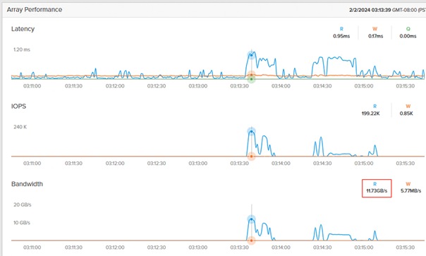
Note: The bandwidth shown above is delivered for a single DSS VM test (with 4x 32Gbps Pure Storage array ports leveraged) and not the maximum bandwidth that Pure Storage FlashArray//XL170 can deliver.
To show that the numbers in Figure 40 do not indicate the storage array’s maximum performance numbers, another DSS SQL VM (with same specifications mentioned in the above table) is spun off on a different ESXi host connected to same Pure Storage FlashArray //XL170 array using another set of 4x 32Gbps ports. The same test is repeated on the two VMs in parallel and captured the bandwidth delivered by the same underlying storage array. As shown below, the //XL170 array could deliver nearly 22GB/s (almost double the Single DSS VM’s bandwidth) and the two VMs together took the same or better time as that of single DSS VM to complete the query execution. Again, the two VM numbers do not indicate the maximum performance numbers of the array.
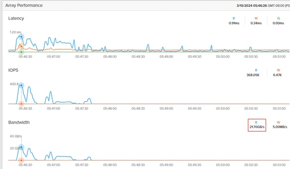
Table 15 lists more details on the tests conducted above.
Table 15. DSS workload Tests and Results
| Component |
Time Taken (Sec) to complete Query Set (22 Queries) |
Geomean of 22 Queries |
Peak Storage Bandwidth Delivered (GB/s) |
| Single DSS VM test |
85 |
2.35 |
11.73 |
| Two DSS VMs test |
88 (VM1) and 95 (VM2) |
2.35 and 2.46 |
21.70 |
These tests demonstrate the heavy bandwidth demands of DSS workloads can be easily virtualized and consolidated on the FlashStack system backed by the Pure Storage FlashArray//XL170 storage array.
Intel QAT Accelerator for Database Backup Performance Improvement
The objective of this section is to demonstrate the benefits of using Intel QAT hardware accelerator cores for improving Microsoft SQL Server database backup performance when compared to SQL Server native backup compression.
Required Intel QAT drivers downloaded and installed at ESXi hypervisor and Windows Guest level and configured SQL Server to leverage the Intel QAT hardware accelerators. To use the QAT accelerators for backup compression, set “algorithm” parameter to “qat_deflate” in the backup command. For SQL Server native compression for backup compression, set “algorithm” parameter to “ms_xpress.” The following figure provides more details on the benefits that customers get by offloading Microsoft SQL Server database backups to Intel QAT accelerators when compared to SQL Server native compression.
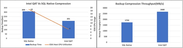
As shown in Figure 42, backup duration with Intel QAT compression is nearly 1.5 times reduced compared to the SQL server native backup compression algorithm. The ESXi CPU utilization during compression with Intel QAT is around 6%, whereas CPU utilization with SQL Server native compression is 19% which is nearly 3 times higher. The reduction in CPU usage with QAT is due to the compression being offloaded from actual CPU cores to Intel integrated QAT accelerator cores. The freed CPU cycles can be used for executing actual customer workload. Also, Intel QAT can process the compression at nearly 2680 MB/s speed, while SQL native compression speed by comparison is around 1750 MB/s which is 1.5 times less than QAT throughput.
Here are the advantages of using Cisco UCS X210c M7 compute nodes powered by Intel 4th-generation Xeon Scalable processors with the Intel Quick Assist Technology accelerator for backup compression:
● Achieve better Return on Investment (ROI) by offloading CPU-intensive compression/decompression operations to Intel QAT accelerators.
● Achieve nearly 1.5 times reduction in the duration of Microsoft SQL Server backup by offloading compression to Intel QAT.
● Faster backup/restore times enable customers to reduce the maintenance window times for critical production environments, thereby increasing availability of the databases.
● Freed CPU cycles (nearly 3 times) of processors can be used for executing actual customer workloads.
Pure Storage Snapshots for SQL Server Database
Crash-Consistent Database Snapshots
Complete the following procedure to take Crash-Consistent database snapshots.
Procedure 1. SQL Server database Crash-Consistent snapshots
Step 1. Login to Pure and navigate to Protection and click Protection Group. Provide a name to the Protection Group and click Create.
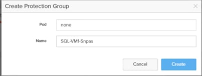
Step 2. Click the Protection Group and then click ‘+’ symbol to all the members to the Protection group. Add all the volumes (including data, config, and swap) of SQL virtual machine for consistent snapshot as shown below.
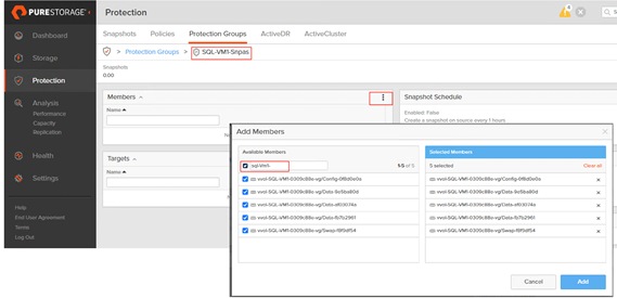
Step 3. Set the frequency of snapshot by creating a Snapshot Schedule as shown below. For the demo purposes, 10min frequency is selected.
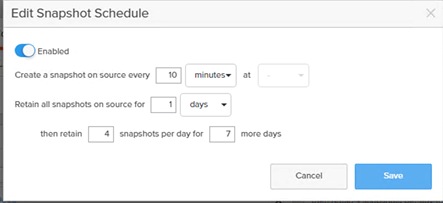
Step 4. Wait for some time to create the first snapshot by Pure storage. You can view the newly created snapshots by navigating to Pure Storage > Protection > Snapshots (search the snapshots by SQL VM name) as shown below.
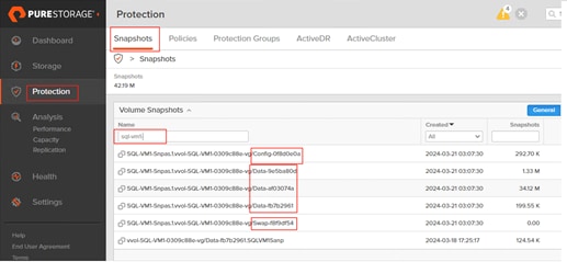
Step 5. Due to a human or system mistake, you want to revert your database state to the point when the snapshot was taken. You can import the snapshot of the SQL volumes to the same or different VMs. To restore the database to the previous state, SQL Server VM needs to be shutdown. Navigate to the vCenter > select the SQL VM > Configure > Pure Storage > Pure Volumes. Click Import Disk. Select Disk one by one (where SQL Server database data files are stored) and select the first snapshot and click Import.
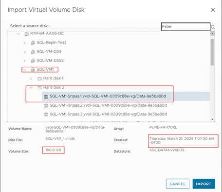
Step 6. Repeat Step 5 for all the data and T-Log virtual disks. For every snapshot you import, the Pure Storage will create a new volume and attach it to the same/different VM ( based on the selection). Once the snapshots for all the database disks are imported, you can power on the VM and check if the disks are attached to the VM using Disk Management utility. As shown in the following figure, the Pure storage created two new disks (3 and 4) and attached them to the VM. Bring the disks online and change the Disk Drive letter (X and Y) as shown below.
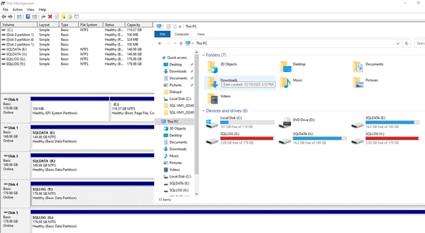
Step 7. Open the Management studio and attach the database using the database files located on the newly created drives (X and Y drives in this example). This copy of the database will not have the changes that were made after the snapshot was taken.
Cloud Block Storage (CBS) Asynchronous Replication for Disaster Recovery
This section provides the steps to configure and replicate SQL Server volumes from On-Prem FlashArray to CBS hosted in Azure Cloud using Asynchronous replication with periodical snapshots.
Complete the following procedure to configure Asynchronous Replication between On-Prem FlashArray and CBS hosted in Azure cloud.
Procedure 1. Connect and Configure Replication from on-premises FlashArray to CBS
Step 1. Login to the CBS and get access code by going to Protection > Array Connections > Connection Key. Copy the Connection Key.
Step 2. Login to the on-premises FlashArray and establish connection to the CBS by clicking Storage > Array > Connect Array. Provide required information and click Connect to connect the on-premises array to CBS.

Step 3. Provide the CBS floating IP address for the Management Address, Set Type as Asynchronous Replication, Paste the Connection Key obtained from Step 1, set Replication Transport as Ethernet(IP), and optionally provide the Replication addresses of the CBS interfaces which are enabled for Replication services.
Once connection is established to the CBS, the CBS will be listed under the connected Arrays list as shown below. Verify and ensure the Connected Array list of CBS will now show up the on-premises FlashArray automatically.
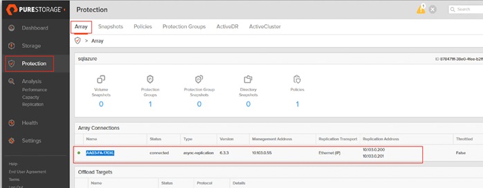
Procedure 2. Create Protection Group, set Replication Schedule (periodic snapshot), and add CBS as Target
The next step is to create a Protection Group in the on-premises array, define the replication frequency and then add the target storage array to which the protected Group will be replicated.
Step 1. Connect to on-premises FlashArray and create a Protection Group by going to Protection > Protection Groups > source Protection Groups. Provide a name to the Protection Group as shown below.
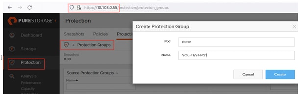
Step 2. Click the newly created Protection Group and set the Replication Schedule as shown below. Minimum allowed frequency is 5 minutes and 400 days of retention.
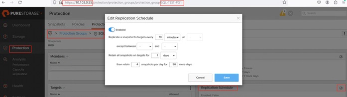
Step 3. Click the Targets of the Protection Group and add CBS as the Target Array as shown below.
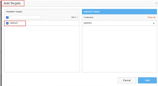
Procedure 3. Create vSphere Storage Policy for VMs volumes and associate SQL volumes
The next step is to create vSphere storage policy by referencing the Protection Group created in the previous step and then associated it to the volumes which you want to replicate to CBS.
Step 1. Login to vCenter and launch the Pure Storage Plugin, select on-premises storage array, and create storage policy.
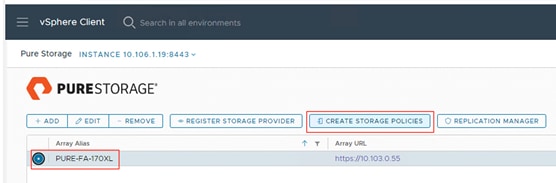
Step 2. Under the Select Feature tab, check Remote Replication Protection as shown below and click Next. Under Array Compatibility, select on-premises array listing the vVolume and click Next.
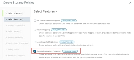
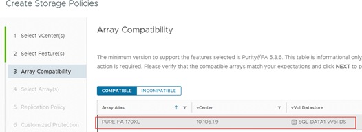
Step 3. Under the Select Array tab, select No and click Next. Under the Replication Policy select Yes and select the on-premises array and the Protection Group that was created in the previous steps. Click Next.
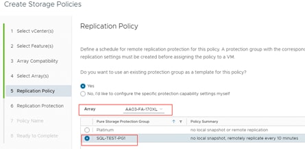
Step 4. Under the Replication Protection tab, verify if the same replication settings that you set for Protection Groups are appearing now and ensure that CBS is listed under Target Sites. Click Next.
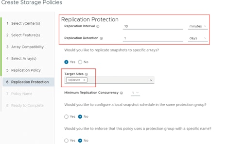
Step 5. Provide a name to the Protection Group and complete the wizard.
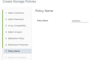
Procedure 4. Create SQL VM and add vVol Virtual Disks for SQL Database files and associate the Storage Policy
The next step is to create (or edit existing VM) a new virtual machine for SQL Server instance and select the storage policy (created in previous steps) for the vVol virtual disks which are used for storing the database data and T-Log files. Once this is done, the snapshots will be automatically triggered by the on-premises Pure Storage and then replicated to CBD hosted in Azure.
Step 1. Before start using the storage policy for the SQL VMs, the Configure Per disk option needs to be enabled to use the storage policy at the disk level. Right-click the VM, select VM Policies, and select Edit VM Storage Policies. Enable the Configure per disk as shown below.
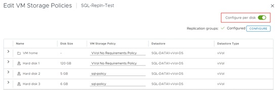
Step 2. Edit SQL VM’s virtual disk settings and set the storage policy to the policy created in the previous step for the vVols where the SQL Server databases data and T-Log files are stored. Optionally, you can also change storage policy for OS disk.
Note: For simplicity purposes, two small volumes of sizes 6GB and 5GB were created for storing database data and log files.
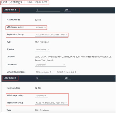
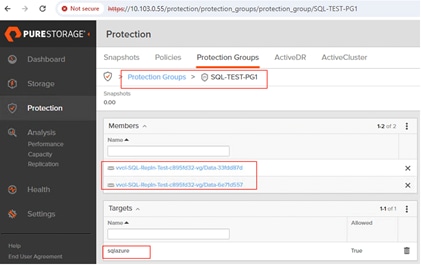
The administrator can now start creating databases on these protected volumes and use them for storing their data.
Procedure 5. Verify the Replication
Wait for the first replication snapshot to be kicked off and replicated to CBS (in this example, 10 minutes). Verify the snapshots from on-premises are getting replicated to CBS.
Step 1. Connect CBS and verify if the snapshots are listed under Volume Snapshots as shown below. As shown in the below screenshot, the snapshots of the data volume (xx-6e71d557) and T-Log volume (33fdd87d) pair are getting created and replicated for every 10 minutes.
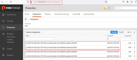
These volumes can be easily converted or copied to new volumes on CBS and can be consumed by any Azure VMs.
Procedure 6. Copy the Snapshots to volumes on CBS and consume them by Azure VMs
You can select any Snapshot on CBS and copy it as volume which can be consumed by Azure VM.
Step 1. Connect CBS and select the Snapshot you want to copy it as a volume and select Copy. Set None for Pod or Volume Group and provide a name for the new volume as shown below for T-Log volume (33fdd87d). Repeated the same step for the data disk and named it as Data-Vol.
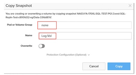
Once the volumes are created, you can view them in CBS as standard volumes. The standard procedures (for instance, connecting to the storage array using in-guest iSCSI initiator method) can be followed to allow the Azure VMs to access these newly created data and log volumes. The following screenshot shows a host (created in Azure Cloud) “AzureSQLVM” with an IQN and granted access to the two volumes previously created.
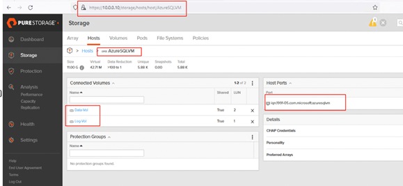
Once access to these volumes is granted to Azure VM, connect to the volumes using the Windows iSCSI initiator, verify if the database files are available and start using them by simply attaching them using SQL Server management studio or T-SQL commands. The following figure shows the volumes and the database data (.mdf) files within Azure VM after connecting to the volumes using windows iSCSI initiator.
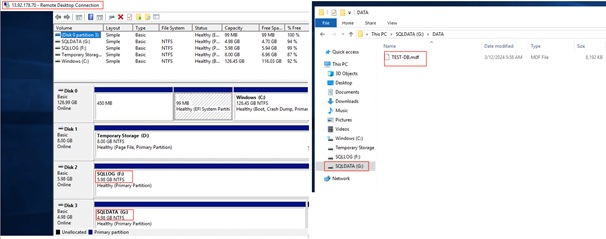
Conclusion
FlashStack is the optimal shared infrastructure foundation to deploy a variety of IT workloads. The solution discussed in this document is built on the latest hardware and software components to take maximum advantage of both Cisco UCS compute and Pure Storage for deploying performance sensitive workloads such as Microsoft SQL Server databases.
In addition to the traditional enterprise grade offerings such as snapshots, clones, backups, Quality of Service, by adapting NVMe-oF technologies, this solution extends both Flash and NVMe performance to the multiple ESXi servers over the traditional Fibre Channel fabrics. This CVD provides a detailed guide for deploying Microsoft SQL Server 2022 database on vSphere cluster. The performance tests detailed in this document validates the FlashStack solution delivering a consistent high throughput at sub-millisecond latency required for high performance, mission critical databases. The DSS workload test demonstrates that the high bandwidth capabilities of Pure Storage FlashArray//XL170 enables customers to virtualize and consolidate even DSS workloads on the FlashStack system.
This document also describes the performance benefits of using Intel QAT technology by offloading SQL Server backup compression to the built-in hardware accelerators compared to SQL Server native compression. Pure Storage storage array snapshots enable data mobility and data resiliency in conjunction with SQL Server databases. The Pure Storage plugin for vSphere enables customers to perform most of the day-to-day Pure Storage management activities like managing datastores, Snapshots, clones, replication and so on, from vCenter itself and greatly simplifies these tasks. Finally, the document describes the Cloud Block Storage (CBS) deployment steps and shows how to configure and achieve seamless disaster recovery of SQL Server databases by replicating the data from on-premises to cloud.
Gopu Narasimha Reddy, Technical Marketing Engineer, Cisco Systems, Inc.
Gopu Narasimha Reddy is a Technical Marketing Engineer in the Cisco UCS Datacenter Solutions group. Currently, he is focusing on developing, testing, and validating solutions on the Cisco UCS platform for Microsoft SQL Server databases on Microsoft Windows, VMware, and Kubernetes platforms. He is also involved in publishing TPC-H database benchmarks on Cisco UCS servers. His areas of interest include building and validating reference architectures, development of sizing tools in addition to assisting customers in SQL deployments.
Acknowledgements
For their support and contribution to the design, validation, and creation of this Cisco Validated Design, the authors would like to thank:
● John McAbel, Product Manager, Cisco Systems, Inc.
● Babu Mahadevan, Technical Leader, Cisco Systems, Inc.
● Chris O'Brien, Director, UCS Solutions, Cisco Systems, Inc.
● Andy Yun, Field Solutions Architect, Pure Storage, Inc.
● Craig Waters, Technical Director, Cisco Solutions, Pure Storage, Inc.
● Vijay Kulari, Senior Solutions Architect, Pure Storage, Inc.
This appendix contains the following:
● Appendix A - References used in this guide
Appendix A – References used in this guide
Cisco UCS Design Guides: https://www.cisco.com/c/en/us/solutions/design-zone.html
FlashStack VSI with VMware 8.0, UCS M7 and Pure Storage FlashArray:
Cisco Intersight: https://www.intersight.com
Cisco Intersight Managed Mode: https://www.cisco.com/c/en/us/td/docs/unified_computing/Intersight/b_Intersight_Managed_Mode_Configuration_Guide.html
Cisco Unified Computing System: http://www.cisco.com/en/US/products/ps10265/index.html
Cisco UCS 6536 Fabric Interconnects: https://www.cisco.com/c/en/us/products/collateral/servers-unified-computing/ucs6536-fabric-interconnect-ds.html
Cisco Nexus 9000 Series Switches: http://www.cisco.com/c/en/us/products/switches/nexus-9000-series-switches/index.html
Cisco MDS 9132T Switches: https://www.cisco.com/c/en/us/products/collateral/storage-networking/mds-9100-series-multilayer-fabric-switches/datasheet-c78-739613.html
Storage
Pure Storage FlashArray//XL: https://www.purestorage.com/products/nvme/flasharray-xl.html
Pure Storage Plugin for vSphere Client: https://support.purestorage.com/Solutions/VMware_Platform_Guide/Release_Notes_for_VMware_Solutions/Release_Notes%3A_Pure_Storage_Plugin_for_the_vSphere_Client
VMware vCenter Server: http://www.vmware.com/products/vcenter-server/overview.html
VMware vSphere: https://www.vmware.com/products/vsphere
Cisco UCS Hardware Compatibility Matrix: https://ucshcltool.cloudapps.cisco.com/public/
VMware and Cisco Unified Computing System: http://www.vmware.com/resources/compatibility
Pure Storage FlashArray Interoperability metrics: https://support.purestorage.com/FlashStack/Product_Information/FlashStack_Compatibility_Matrix
For comments and suggestions about this guide and related guides, join the discussion on Cisco Community at https://cs.co/en-cvds.
CVD Program
ALL DESIGNS, SPECIFICATIONS, STATEMENTS, INFORMATION, AND RECOMMENDATIONS (COLLECTIVELY, "DESIGNS") IN THIS MANUAL ARE PRESENTED "AS IS," WITH ALL FAULTS. CISCO AND ITS SUPPLIERS DISCLAIM ALL WARRANTIES, INCLUDING, WITHOUT LIMITATION, THE WARRANTY OF MERCHANTABILITY, FITNESS FOR A PARTICULAR PURPOSE AND NONINFRINGEMENT OR ARISING FROM A COURSE OF DEALING, USAGE, OR TRADE PRACTICE. IN NO EVENT SHALL CISCO OR ITS SUPPLIERS BE LIABLE FOR ANY INDIRECT, SPECIAL, CONSEQUENTIAL, OR INCIDENTAL DAMAGES, INCLUDING, WITHOUT LIMITATION, LOST PROFITS OR LOSS OR DAMAGE TO DATA ARISING OUT OF THE USE OR INABILITY TO USE THE DESIGNS, EVEN IF CISCO OR ITS SUPPLIERS HAVE BEEN ADVISED OF THE POSSIBILITY OF SUCH DAMAGES.
THE DESIGNS ARE SUBJECT TO CHANGE WITHOUT NOTICE. USERS ARE SOLELY RESPONSIBLE FOR THEIR APPLICATION OF THE DESIGNS. THE DESIGNS DO NOT CONSTITUTE THE TECHNICAL OR OTHER PROFESSIONAL ADVICE OF CISCO, ITS SUPPLIERS OR PARTNERS. USERS SHOULD CONSULT THEIR OWN TECHNICAL ADVISORS BEFORE IMPLEMENTING THE DESIGNS. RESULTS MAY VARY DEPENDING ON FACTORS NOT TESTED BY CISCO.
CCDE, CCENT, Cisco Eos, Cisco Lumin, Cisco Nexus, Cisco StadiumVision, Cisco TelePresence, Cisco WebEx, the Cisco logo, DCE, and Welcome to the Human Network are trademarks; Changing the Way We Work, Live, Play, and Learn and Cisco Store are service marks; and Access Registrar, Aironet, AsyncOS, Bringing the Meeting To You, Catalyst, CCDA, CCDP, CCIE, CCIP, CCNA, CCNP, CCSP, CCVP, Cisco, the Cisco Certified Internetwork Expert logo, Cisco IOS, Cisco Press, Cisco Systems, Cisco Systems Capital, the Cisco Systems logo, Cisco Unified Computing System (Cisco UCS), Cisco UCS B-Series Blade Servers, Cisco UCS C-Series Rack Servers, Cisco UCS S-Series Storage Servers, Cisco UCS X-Series, Cisco UCS Manager, Cisco UCS Management Software, Cisco Unified Fabric, Cisco Application Centric Infrastructure, Cisco Nexus 9000 Series, Cisco Nexus 7000 Series. Cisco Prime Data Center Network Manager, Cisco NX-OS Software, Cisco MDS Series, Cisco Unity, Collaboration Without Limitation, EtherFast, EtherSwitch, Event Center, Fast Step, Follow Me Browsing, FormShare, GigaDrive, HomeLink, Internet Quotient, IOS, iPhone, iQuick Study, LightStream, Linksys, MediaTone, MeetingPlace, MeetingPlace Chime Sound, MGX, Networkers, Networking Academy, Network Registrar, PCNow, PIX, PowerPanels, ProConnect, ScriptShare, SenderBase, SMARTnet, Spectrum Expert, StackWise, The Fastest Way to Increase Your Internet Quotient, TransPath, WebEx, and the WebEx logo are registered trade-marks of Cisco Systems, Inc. and/or its affiliates in the United States and certain other countries. (LDW_P3)
All other trademarks mentioned in this document or website are the property of their respective owners. The use of the word partner does not imply a partnership relationship between Cisco and any other company. (0809R)