FlashStack for SQL Server 2019 with Cisco UCS X-Series and Pure Storage FlashArray//XL170
Available Languages
Bias-Free Language
The documentation set for this product strives to use bias-free language. For the purposes of this documentation set, bias-free is defined as language that does not imply discrimination based on age, disability, gender, racial identity, ethnic identity, sexual orientation, socioeconomic status, and intersectionality. Exceptions may be present in the documentation due to language that is hardcoded in the user interfaces of the product software, language used based on RFP documentation, or language that is used by a referenced third-party product. Learn more about how Cisco is using Inclusive Language.
- US/Canada 800-553-2447
- Worldwide Support Phone Numbers
- All Tools
 Feedback
 Feedback

In partnership with:
![]()
About the Cisco Validated Design Program
The Cisco Validated Design (CVD) program consists of systems and solutions designed, tested, and documented to facilitate faster, more reliable, and more predictable customer deployments. For more information, go to: http://www.cisco.com/go/designzone.
The ever-changing business needs demands the organizations to adapt modern business delivery technologies, tools, platform, and systems that enables them to develop, test and deploy their applications quickly and continuously. Consistent performance, scalability, high availability, disaster recovery capabilities, patch management, automation and full stack monitoring are few other challenges organizations are facing today.
The FlashStack solution is a validated, converged infrastructure developed jointly by Cisco and Pure Storage. The solution offers a predesigned data center architecture that incorporates computing, storage, and network design best practices to reduce IT risk by validating the architecture and helping to ensure compatibility among the components. The solution also addresses IT pain points by providing documented design and deployment guidance and support that can be used in various stages (planning, designing and implementation) of a deployment. The FlashStack solution provides consistent performance, scalable and agile system by combining and stitching the best breeds of software technologies and modern hardware from the two partners.
Red Hat OpenShift Container Platform (OCP) is one of the leading Kubernetes based containerized platforms with full stack automated operations to manage on-prem, hybrid and multi-cloud deployments. It provides a self-service platform to create, modify, and deploy applications on demand anywhere either in on-prem, cloud or a mix of both, thus enabling faster development and release life cycles.
Portworx Enterprise is a fully featured enterprise class storage platform. It is fully integrated with OCP and enables customers to efficiently achieve the life cycle management of persistent storage requirements of containerized production deployments with confidence.
The combination of FlashStack System and OCP backed by Portworx Enterprise storage platform, provides a pre-validated, high performing, agile and scalable system that enables customer to achieve modern application development practices for deploying critical business applications that demand high cpu and io intensive components such as databases.
This document explains the FlashStack system tested and validated for containerized Microsoft SQL Server databases deployments on OCP running on VMware vSphere Cluster using Cisco UCS X-Series modular Platform, Pure Storage FlashArray//XL170. The document also explains performance validation tests to demonstrate the SQL Server database performance scalability using the Portworx storage volumes.
This chapter contains the following:
● Audience
Organizations are rapidly adapting application modernization by containerizing their applications and adapting microservices architecture while deploying their complex applications. Kubernetes is a leading open-source container orchestration engine with many built-in features that enables rapid application deployment, scalability, and other maintenance operations. However, the generic Kubernetes deployments lack many features like consistent security, built-in monitoring capabilities, centralized policy management and importantly the enterprise-class support necessary for organizations to implement robust and reliable containerized environments.
Red Hat OpenShift Container Platform (OCP), built on Kubernetes foundations, offers self-service provisioning, strict security policies, built-in management, and monitoring tools, integrates with variety third party tools and vendors while leveraging leading Red Hat Enterprise Linux Operating System and offers full technical support from Red Hat.
The featured FlashStack system for OpenShift Container platform is a pre-designed, integrated, and validated architecture for the data center that combines Cisco UCS servers, the Cisco Nexus family of switches, and Pure Storage into a single, flexible architecture. It is designed for high availability (HA), with no single point of failure, while maintaining cost-effectiveness and flexibility in the design to support a wide variety of workloads. The FlashStack solution covered in this document is for virtualization implementation of Red Hat OpenShift Container Platform installer provisioned infrastructure (IPI), built on Enterprise Kubernetes for an on-premises deployment.
Microsoft SQL Server (MSSQL) database is one of the popular relational database engines adapted by many customers for their backend database services. Containerization of the MSSQL database engine has been supported since 2017. As with any database deployments, MSSQL containers need persistent storage for storing their data and transaction log files persistently. Kubernetes offers the Container Storage Interface (CSI) framework for storage system providers to write plugins against, to enable containers to request, provision and utilize storage as they demand.
Portworx by Pure Storage provides a fully integrated solution for persistent storage, data protection, disaster recovery, data security, cross-cloud and data migrations, and automated capacity management for applications running on Kubernetes. The tight integration of Portworx with OCP enables quick provisioning and life-cycle management of storage volumes for containerized applications. Portworx can be easily deployed and managed with just a few clicks and commands from the OCP console.
This document explains the deployment best practices designing FlashStack System for running MSSQL databases on OCP cluster using Pure Storage Portworx storage provision platform and along with performance validation and their results to demonstrate how the application performance can be easily scaled over the FlashStack System.
The intended audience of this document includes but is not limited to IT architects, sales engineers, database administrators, field consultants, professional services, IT managers, partner engineering, and customers who want to take advantage of an infrastructure built to deliver IT efficiency and enable IT innovation. It is expected that the reader should have familiarity with the FlashStack architectures and container orchestrations such as the Red Hat Open Shift platform.
This document describes a FlashStack reference architecture with implementation best practices for deploying Microsoft SQL Server 2019 database containers on Red Hat OpenShift Container Platform on a FlashStack system built using Cisco UCS X-Series and Pure Storage FlashArray storage using FC-NVMe storage protocol.
The intention of this document is not to provide a detailed step-by-step guide for deployment of the FlashStack solution with VMware vSphere and OpenShift Platform. Rather, it explains specific configurations and best practices for running containerized Microsoft SQL Server databases on the FlashStack system.
● Microsoft SQL Server 2019 database as a container deployment on Red Hat OCP running on VMware vSphere cluster using ESXi 7.0 U3.
● Portworx Enterprise as a high performing and resilient storage provisioning platform for containerized MSSQL databases.
● Red Hat OpenShift Container Platform backed by Portworx persistent storage provisioning platform for running SQL Server databases with confidence in production environments.
● Integration of the Cisco UCS X-Series X210c blades for compute.
● Integration of Pure Storage FlashArray//XL170 with NVMe over Fibre Channel (NVMe-FC) connectivity using Cisco MDS 32Gbps Fibre channel switches.
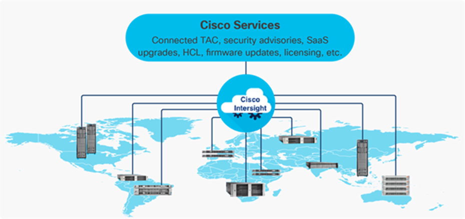
● Cisco Intersight cloud platform for managing and monitoring Cisco UCS X-Series Chassis.
● Cisco Intersight Assist for Pure Storage FlashArray monitoring and orchestration of storage.
● Cisco Intersight Assist for VMware vCenter for Interaction, monitoring, and orchestration of the virtual environment.
Solution Summary
This FlashStack solution, which is built for confidently running enterprise grade containerized Microsoft SQL Server databases, comprises the following components.
● Compute and networking components from Cisco
● Storage Systems and Portworx storage provisioning platform for containers from Pure Storage.
● Server virtualization using VMware vSphere
● OpenShift Red Hat Container Platform from Red Hat
Bringing a carefully validated architecture built on superior compute, world-class networking, and the leading innovations in All Flash storage. These components are integrated and validated, and the entire stack is automated so that customers can deploy the solution quickly and efficiently while eliminating many of the risks associated with researching, designing, building, and deploying similar solutions from the ground up.
This FlashStack solution designed with Cisco UCS X-Series, Cisco UCS 4th Generation Fabric Technology and VMware 7.0 U3 is configurable according to the demand and usage. Customers can purchase exactly the infrastructure they need for their current application requirements, then can scale up by adding more resources to the FlashStack system or scale out by adding more FlashStack instances. By moving the management from the fabric interconnects into the cloud, the solution can respond to speed and scale of customer deployments with a constant stream of new capabilities delivered from the Cisco Intersight SaaS model at cloud scale.
Figure 1 illustrates the core components used in this FlashStack solution.
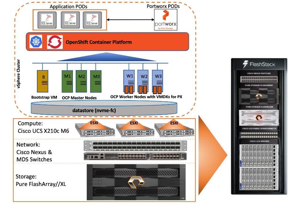
As shown in Figure 1, the reference architecture leverages the Pure Storage FlashArray//XL170 controllers for shared storage, Cisco UCS X9508 chassis with Cisco UCS X210c server blades for compute, Cisco MDS 9000 Series switches for storage connectivity using NVMe over Fibre Channel protocol, Cisco Nexus 9000 Series Ethernet switches for networking element and Cisco Fabric Interconnects 6400 Series for System Management. Cisco Intersight is used for managing and orchestrating the Cisco UCS blade chassis, Cisco UCS Fabric Interconnect, and Pure Storage FlashArray//XL170. Red Hat OCP is used as a container orchestration engine for running MSSQL databases by leveraging the storage services from Portworx.
The components of FlashStack architecture are connected and configured according to best practices of both Cisco and Pure Storage and provides the ideal platform for running a variety of enterprise database workloads with confidence. FlashStack can scale up for greater performance and capacity (adding compute, network, or storage resources independently as needed), or it can scale out for environments that require multiple consistent deployments. The architecture brings together a simple, wire once solution that is SAN booted from FC and is highly resilient at each layer of the design.
Cisco and Pure Storage have also built a robust and experienced support team focused on FlashStack solutions, from customer account and technical sales representatives to professional services and technical support engineers. The support alliance between Pure Storage and Cisco gives customers and channel services partners direct access to technical experts who collaborate across vendors and have access to shared lab resources to resolve potential issues.
For more details and specifications of individual components, go to the References section where all the necessary links are provided.
This chapter contains the following:
● Cisco Unified Compute System X-Series
● Cisco UCS 6400 Series Fabric Interconnects
● Cisco Nexus Switching Fabric
● Cisco MDS 9132T 32G Multilayer Fabric Switch
● Red Hat OpenShift Container Platform (OCP)
● Pure Portworx Storage Provisioning Platform
● Cisco Intersight Assist Device Connector for VMware vCenter and Pure Storage FlashArray
FlashStack architecture is built using the following infrastructure components for compute, network, and storage (Figure 2):
● Cisco Unified Computing System (Cisco UCS)
● Cisco Nexus 9000 switches
● Cisco MDS 9000 switches
● Pure Storage FlashArray
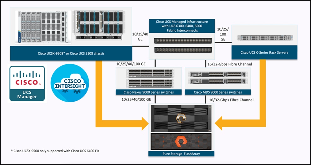
All the FlashStack components are integrated, so customers can deploy the solution quickly and economically while eliminating many of the risks associated with researching, designing, building, and deploying similar solutions from the foundation. One of the main benefits of FlashStack is its ability to maintain consistency at scale. Each of the component families shown in Figure 2 (Cisco UCS, Cisco Nexus, Cisco MDS, and Pure Storage FlashArray systems) offers platform and resource options to scale up or scale out the infrastructure while supporting the same features and functions.
Note that 5th Generation Fabric Interconnects (FI), Intelligent Fabric Modules (IFM) and Virtual Interface Card (VIC) are also validated and supported for FlashStack systems. However, this FlashStack validated design was built and tested with 4th Generation Fabric Interconnects, IFMs and VICs.
This FlashStack solution discussed in this document comprises the following hardware and software components:
● Cisco UCS X9508 Chassis with Cisco UCS X210c M6 compute nodes installed with 4th Generation Cisco VIC 14425 and with Cisco UCS 9108 25G Intelligent Fabric Module to connect the I/O fabric between the 6400 Fabric Interconnect and the Cisco UCS X9508 Chassis
● Cisco 4th Generation Cisco UCS 6400 Fabric Interconnects to support 25 and 100 Gigabit Ethernet connectivity from various components
● High-Speed Cisco NX-OS based Nexus 93360YC-FX2 switching design to support up to 25/40/100GbE connectivity.
● High-Speed Cisco NX-OS based MDS 9132T switching design to support up to 32Gb end-to-end connectivity to support SCSI and NVMe over Fibre Channel.
● Pure Storage FlashArray//XL170 All Flash Storage with high-speed NVMe over Fibre Channel connectivity
The software components consist of:
● Cisco Intersight platform to deploy, maintain, and support the FlashStack components
● Cisco Intersight Assist virtual appliance to help connect the Pure Storage FlashArray and VMware vCenter with the Cisco Intersight platform
● VMware vCenter 7.0 U3 to set up and manage the virtual infrastructure as well as integration of the virtual environment with Cisco Intersight software
● Red Hat OpenShift Container Platform (OCP) 4.10 for hosting containerized SQL Server databases
● Portworx Enterprise v2.12 for persistent storage provisioning for workloads running on OCP
● Microsoft SQL Server 2019 databases
Cisco Unified Computing System X-Series
The Cisco UCS X-Series modular system is designed to take the current generation of the Cisco UCS platform to the next level with its design that will support future innovations and management in the cloud (Figure 3). Decoupling and moving platform management to the cloud allows the Cisco UCS platform to respond to features and scalability requirements much faster and more efficiently. Cisco UCS X-Series state-of-the-art hardware simplifies the datacenter design by providing flexible server options. A single server type that supports a broader range of workloads results in fewer different datacenter products to manage and maintain. The Cisco Intersight cloud management platform manages the Cisco UCS X-Series as well as integrates with third-party devices. These devices include VMware vCenter and Pure Storage to provide visibility, optimization, and orchestration from a single platform, thereby enhancing agility and deployment consistency.
Cisco UCS X9508 Chassis
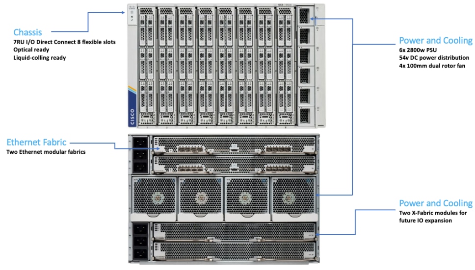
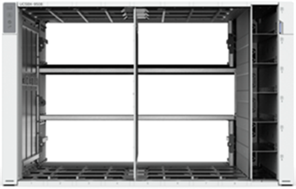
The Cisco UCS X-Series chassis is engineered to be adaptable and flexible. As shown in Figure 4, Cisco UCS X9508 chassis has only a power-distribution midplane. This innovative design provides fewer obstructions for better airflow. For I/O connectivity, vertically oriented compute nodes intersect with horizontally oriented fabric modules, allowing the chassis to support future fabric innovations. Cisco UCS X9508 Chassis’ superior packaging enables larger compute nodes, thereby providing more space for actual compute com-ponents, such as memory, GPU, drives, and accelerators. Improved airflow through the chassis enables support for higher power components, and more space allows for future thermal solutions (such as liquid cooling) without limitations.
The Cisco UCS X9508 7-Rack-Unit (7RU) chassis has eight flexible slots. These slots can house a combination of compute nodes and a pool of future I/O resources that may include GPU accelerators, disk storage, and nonvolatile memory. At the top rear of the chassis are two Intelligent Fabric Modules (IFMs) that connect the chassis to upstream Cisco UCS 6400 Series Fabric Interconnects. At the bottom rear of the chassis are slots ready to house future X-Fabric modules that can flexibly connect the compute nodes with I/O devices. Six 2800W Power Supply Units (PSUs) provide 54V power to the chassis with N, N+1, and N+N redundancy. A higher voltage allows efficient power delivery with less copper and reduced power loss. Efficient, 100mm, dual counter-rotating fans deliver industry-leading airflow and power efficiency, and optimized thermal algorithms enable different cooling modes to best support the customer’s environment.
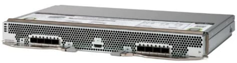
Cisco UCS 9108-25G Intelligent Fabric Module (IFM)
For the Cisco UCS X9508 Chassis, the network connectivity is provided by a pair of Cisco UCSX 9108-25G Intelligent Fabric Modules (IFMs). Like the fabric extenders used in the Cisco UCS 5108 Blade Server Chassis, these modules carry all network traffic to a pair of Cisco UCS 6400 Series Fabric Interconnects (FIs). IFMs also host the Chassis Management Controller (CMC) for chassis management. In contrast to systems with fixed networking components, Cisco UCS X9508s midplane-free design enables easy upgrades to new networking technologies as they emerge making it straightforward to accommodate new network speeds or technologies in the future.
Each IFM supports eight 25Gb uplink ports for connecting the Cisco UCS X9508 Chassis to the FIs and 32 25Gb server ports for the eight compute nodes. IFM server ports can provide up to 200 Gbps of unified fabric connectivity per compute node across the two IFMs. The uplink ports connect the chassis to the Cisco UCS FIs, providing up to 400Gbps connectivity across the two IFMs. The unified fabric carries management, VM, and Fibre Channel over Ethernet (FCoE) traffic to the FIs, where management traffic is routed to the Cisco Intersight cloud operations platform, FCoE traffic is forwarded to the native Fibre Channel interfaces through unified ports on the FI (to Cisco MDS switches), and Ethernet traffic is forwarded upstream to the data center network (via Cisco Nexus switches).
Cisco UCS X210c M6 Compute Node
The Cisco UCS X9508 Chassis is designed to host up to 8 Cisco UCS X210c M6 Compute Nodes. The hardware details of the Cisco UCS X210c M6 Compute Nodes are shown in Figure 6:
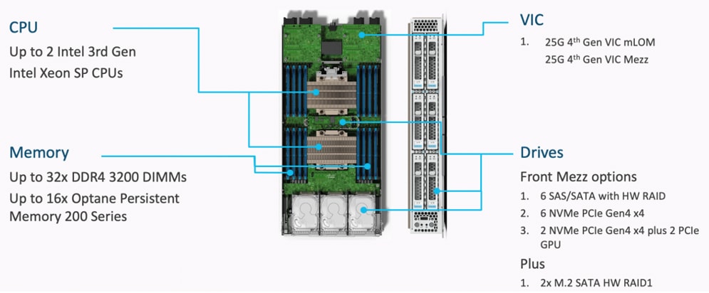
The Cisco UCS X210c M6 features:
● CPU: Up to 2x 3rd Gen Intel Xeon Scalable Processors with up to 40 cores per processor and 1.5 MB Level 3 cache per core
● Memory: Up to 32 x 256 GB DDR4-3200 DIMMs for a maximum of 8 TB of main memory.
● Disk storage: Up to 6 SAS or SATA drives can be configured with an internal RAID controller, or customers can configure up to 6 NVMe drives. 2 M.2 memory cards can be added to the Compute Node with RAID 1 mirroring.
● Virtual Interface Card (VIC): Up to 2 VICs including an mLOM Cisco VIC 15231 or 14425 and a mezzanine Cisco VIC card 14825 can be installed in a Compute Node.
● Security: The server supports an optional Trusted Platform Module (TPM). Additional security features include a secure boot FPGA and ACT2 anticounterfeit provisions.
Cisco UCS Virtual Interface Cards
Cisco UCS X210c M6 Compute Nodes supports fourth generation Cisco UCS VIC 14425 and Cisco UCS VIC 14825. This FlashStack solution with Cisco UCS X-Series and 4th Generation Fabric technology uses Cisco UCS VIC 14425 to enable.
Cisco VIC 14425
Cisco VIC 14425 fits the mLOM slot in the Cisco X210c Compute Node and enables up to 50 Gbps of unified fabric connectivity to each of the chassis IFMs for a total of 100 Gbps of connectivity per server. Cisco VIC 14425 connectivity to the IFM and up to the fabric interconnects is delivered through 4x 25-Gbps connections, which are configured automatically as 2x 50-Gbps port channels. Cisco VIC 14425 supports 256 virtual interfaces (both Fibre Channel and Ethernet) along with the latest networking innovations such as NVMeoF over RDMA (ROCEv2), VxLAN/NVGRE offload, and so on.
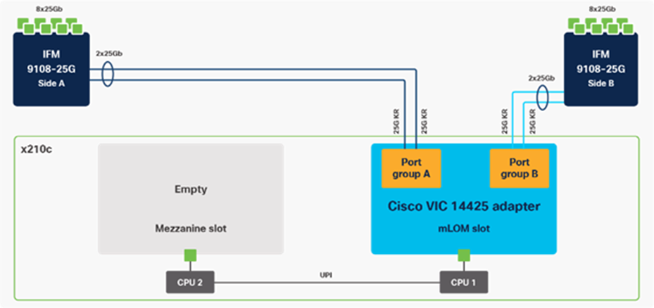
The connections between the 4th generation Cisco VIC (Cisco UCS VIC 1440) plus Port Expander in the Cisco UCS B200 blades and the I/O modules in the Cisco UCS 5108 chassis comprised of multiple 10Gbps KR lanes. The same connections between Cisco VIC 14425 and IFMs in Cisco UCS X-Series comprise of multiple 25Gbps KR lanes resulting in higher speed connectivity in Cisco UCS X210c M6 Compute Nodes.
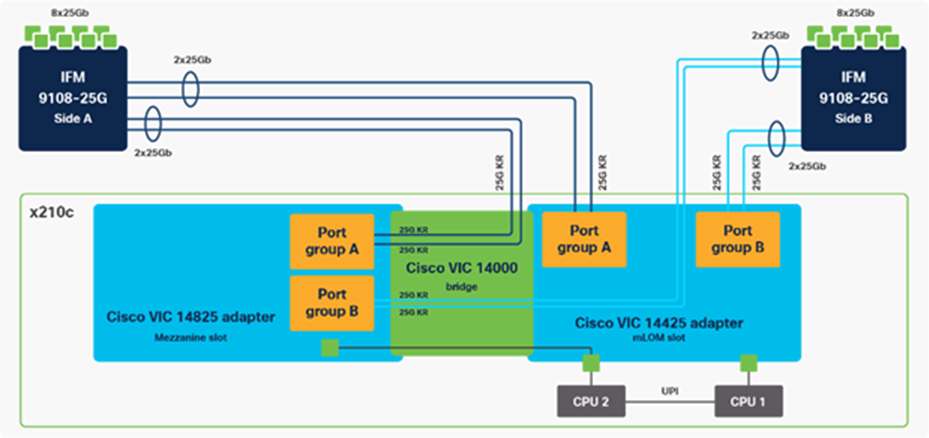
Cisco VIC 14825
The optional Cisco VIC 14825 fits the mezzanine slot on the server. A bridge card (UCSX-V4-BRIDGE) extends this VIC’s 2x 50 Gbps of network connections up to the mLOM slot and out through the mLOM’s IFM connectors, bringing the total bandwidth to 100 Gbps per fabric for a total bandwidth of 200 Gbps per server.
Cisco UCS 6400 Series Fabric Interconnects
The Cisco UCS Fabric Interconnects (FIs) provide a single point of connectivity and management for the entire Cisco UCS system. Typically deployed as an active/active pair, the system’s FIs integrate all components into a single, highly available management domain controlled by the Cisco UCS Manager or Cisco Intersight. Cisco UCS FIs provide a single unified fabric for the system, with low-latency, lossless, cut-through switching that supports LAN, SAN, and management traffic using a single set of cables.
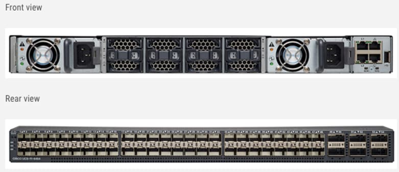
Cisco UCS 6454 utilized in the current design is a 54-port Fabric Interconnect. This single RU device includes 28 10/25 Gbps Ethernet ports, 4 1/10/25-Gbps Ethernet ports, 6 40/100-Gbps Ethernet uplink ports, and 16 unified ports that can support 10/25 Gigabit Ethernet or 8/16/32-Gbps Fibre Channel, depending on the SFP.
Note that for supporting the Cisco UCS X-Series, the fabric interconnects must be configured in Intersight Managed Mode (IMM). This option replaces the local management with Cisco Intersight cloud or appliance-based management.
Cisco UCS Unified fabric: I/O consolidation
The Cisco UCS 6400 series Fabric Interconnect is built to consolidate LAN and SAN traffic onto a single unified fabric, saving on Capital Expenditures (CapEx) and Operating Expenses (OpEx) associated with multiple parallel networks, different types of adapter cards, switching infrastructure, and cabling within racks. The unified ports allow ports in the fabric interconnect to support direct connections from Cisco UCS to existing native Fibre Channel SANs. The capability to connect to a native Fibre Channel protects existing storage-system investments while dramatically simplifying in-rack cabling.
Cisco UCS 6454 Fabric Interconnect supports I/O consolidation with end-to-end network virtualization, visibility, and QoS guarantees for the following LAN and SAN traffic:
● FC SAN, IP Storage (iSCSI, NFS), NVMeoF (NVMe/FC, NVMe/TCP, NVMe over ROCEv2)
● Server management and LAN traffic
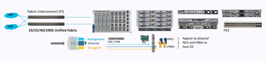
The I/O consolidation under the Cisco UCS 6454 fabric interconnect along with the stateless policy-driven architecture of Cisco UCS and the hardware acceleration of the Cisco UCS Virtual Interface card provides great simplicity, flexibility, resiliency, performance, and TCO savings for the customer’s compute infrastructure.
The Cisco Intersight platform is a Software-as-a-Service (SaaS) infrastructure lifecycle management platform that delivers simplified configuration, deployment, maintenance, and support. The Cisco Intersight platform is designed to be modular, so that customers can adopt services based on their individual requirements. The platform significantly simplifies IT operations by bridging applications with infrastructure, providing visibility and management from bare-metal servers and hypervisors to serverless applications, thereby reducing costs and mitigating risk. This unified SaaS platform uses a unified Open API design that natively integrates with third-party platforms and tools.
The main benefits of Cisco Intersight infrastructure services are as follows:
● Simplify daily operations by automating many daily manual tasks
● Combine the convenience of a SaaS platform with the capability to connect from anywhere and manage infrastructure through a browser or mobile app
● Stay ahead of problems and accelerate trouble resolution through advanced support capabilities
● Gain global visibility of infrastructure health and status along with advanced management and support capabilities
● Upgrade to add workload optimization and Kubernetes services when needed
Cisco Intersight Virtual Appliance and Private Virtual Appliance
In addition to the SaaS deployment model running on Intersight.com, on-premises options can be purchased separately. The Cisco Intersight Virtual Appliance and Cisco Intersight Private Virtual Appliance are available for organizations that have additional data locality or security requirements for managing systems. The Cisco Intersight Virtual Appliance delivers the management features of the Cisco Intersight platform in an easy-to-deploy VMware Open Virtualization Appliance (OVA) or Microsoft Hyper-V Server virtual machine that allows you to control the system details that leave your premises. The Cisco Intersight Private Virtual Appliance is provided in a form factor specifically designed for users who operate in disconnected (air gap) environments. The Private Virtual Appliance requires no connection to public networks or back to Cisco to operate.
Cisco Intersight Assist
Cisco Intersight Assist helps customers add endpoint devices to Cisco Intersight. A data center could have multiple devices that do not connect directly with Cisco Intersight. Any device that is supported by Cisco Intersight but does not connect to Cisco Intersight directly requires Cisco Intersight Assist to provide the necessary connectivity. In FlashStack, VMware vCenter and Pure Storage FlashArray connect to Cisco Intersight through the Cisco Intersight Assist appliance.
Cisco Intersight Assist is available within the Cisco Intersight Virtual Appliance, which is distributed as a deployable virtual machine contained within an Open Virtual Appliance (OVA) file format. More details about the Cisco Intersight Assist VM deployment configuration is explained in later sections.
Licensing Requirements
The Cisco Intersight platform uses a subscription-based license with multiple tiers. Customers can purchase a subscription duration of one, three, or five years and choose the required Cisco UCS server volume tier for the selected subscription duration. Each Cisco endpoint automatically includes a Cisco Intersight Base license at no additional cost when customers access the Cisco Intersight portal and claim a device. Customers can purchase any of the following higher-tier Cisco Intersight licenses using the Cisco ordering tool:
● Cisco Intersight Essentials: Essentials includes all the functions of the Base license plus additional features, including Cisco UCS Central Software and Cisco Integrated Management Controller (IMC) supervisor entitlement, policy-based configuration with server profiles, firmware management, and evaluation of compatibility with the Cisco Hardware Compatibility List (HCL).
● Cisco Intersight Advantage: Advantage offers all the features and functions of the Base and Essentials tiers. It includes storage widgets and cross-domain inventory correlation across compute, storage, and virtual environments (VMware ESXi). It also includes OS installation for supported Cisco UCS platforms.
● Cisco Intersight Premier: In addition to all the functions provided in the Advantage tier, Premier includes full subscription entitlement for Intersight Orchestrator, which provides orchestration across Cisco UCS and third-party systems.
Servers in the Cisco Intersight managed mode require at least the Essentials license. For more information about the features provided in the various licensing tiers, see https://intersight.com/help/getting_started#licensing_requirements.
The Cisco Nexus 9000 Series Switches offer both modular and fixed 1/10/25/40/100 Gigabit Ethernet switch configurations with scalability up to 60 Tbps of non-blocking performance with less than five-microsecond latency, wire speed VXLAN gateway, bridging, and routing support.
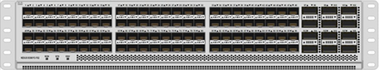
The Cisco Nexus 9000 series switch featured in this design is the Cisco Nexus 93360YC-FX2 configured in NX-OS standalone mode. NX-OS is a purpose-built data-center operating system designed for performance, resiliency, scalability, manageability, and programmability at its foundation. It provides a robust and comprehensive feature set that meets the demanding requirements of virtualization and automation.
The Cisco Nexus 93360YC-FX2 Leaf Switch is a 2-Rack-Unit (2RU) Leaf switch that supports 7.2 Tbps of bandwidth and 2.4 bpps across 96 fixed 10/25G SFP+ ports and 12 fixed 40/100G QSFP28 ports. The 96 ports of downlinks support 1/10/25-Gbps. The 12 uplinks ports can be configured as 40- and 100-Gbps ports, offering flexible migration options. The switch has FC-FEC and RS-FEC enabled for 25Gbps support over longer distances.
Cisco MDS 9132T 32G Multilayer Fabric Switch
The Cisco MDS 9132T 32G Multilayer Fabric Switch is the next generation of the highly reliable, flexible, and low-cost Cisco MDS 9100 Series switches. It combines high performance with exceptional flexibility and cost effective-ness. This powerful, compact one Rack-Unit (1RU) switch scales from 8 to 32 line-rate 32 Gbps Fibre Channel ports.
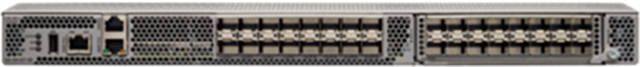
The Cisco MDS 9132T delivers advanced storage networking features and functions with ease of management and compatibility with the entire Cisco MDS 9000 family portfolio for reliable end-to-end connectivity. This switch also offers state-of-the-art SAN analytics and telemetry capabilities that have been built into this next-generation hardware platform. This new state-of-the-art technology couples the next-generation port ASIC with a fully dedicated network processing unit designed to complete analytics calculations in real time. The telemetry data extracted from the inspection of the frame headers are calculated on board (within the switch) and, using an industry-leading open format, can be streamed to any analytics-visualization platform. This switch also includes a dedicated 10/100/1000BASE-T telemetry port to maximize data delivery to any telemetry receiver, including Cisco Data Center Network Manager.
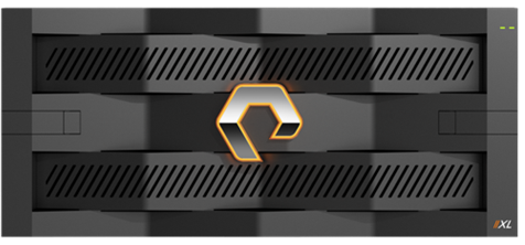
The Pure Storage FlashArray Family delivers software-defined all-flash power and reliability for businesses of every size. FlashArray is all-flash enterprise storage that is up to 10X faster, space and power efficient, reliable, and far simpler than other available solutions. Compared to traditional performance disk arrays, FlashArray costs less with total cost of ownership (TCO) savings of up to 50%. At the top of the FlashArray line is the new FlashArray//XL; this new platform is designed for today’s higher-powered multicore CPUs, allowing //XL to increase performance even over our FlashArray//X models, with more power to take apps to the next level. //XL represents next-level scale and performance for high-demand enterprise applications. The //XL platform enhancements give higher performance, higher capacity density per RU, and higher scale with better resiliency. By being engineered for next-gen CPU and flash technologies to future-proof your investment, you can achieve workload consolidation with room to grow in place, with less frequent servicing by IT staff.
Purity for FlashArray (Purity//FA 6)
Every FlashArray is driven by Purity Operating Environment software. Purity//FA6 implements advanced data reduction, storage management, and flash management features, enabling customers to enjoy tier 1 data services for all workloads. Purity software provides proven 99.9999-percent availability over 2 years, completely nondisruptive operations, 2X better data reduction, and the power and efficiency of DirectFlashTM. Purity also includes enterprise-grade data security, comprehensive data-protection options, and complete business continuity with an ActiveCluster multi-site stretch cluster. All these features are included with every Pure Storage array.
The Pure Storage FlashArray product line includes FlashArray//C, FlashArray//X, and FlashArray//XL.
FlashArray//XL Specification
Table 1 lists both the capacity and physical aspects of various FlashArray systems.
Table 1. FlashArray//XL Specifications
|
|
Capacity |
Physical |
| //XL170 |
Up to 5.5 PB/5.13 PiB effective capacity** Up to 1.4 PB/1.31 PiB raw capacity† |
5RU; 1850–2355 watts (nominal – peak) 167.0lb. (75.7kg) fully loaded; 8.72 x 18.94 x 29.72 in. |
| DirectFlash Shelf |
Up to 1.9 PB effective capacity Up to 512 TB / 448.2 TiB raw capacity |
3U; 460–500 watts (nominal–peak) 87.7 lbs. (39.8 kg) fully loaded; 5.12” x 18.94” x 29.72” |
** Effective capacity assumes high availability, RAID, and metadata overhead, GB-to-GiB conversion, and includes the benefit of data reduction with always-on inline deduplication, compression, and pattern removal. Average data reduction is calculated at 5-to-1 and does not include thin provisioning.
† FlashArray//XL will only support NVMe DirectFlash Modules.
Table 2 lists the various connectivity options using both onboard and host I/O cards.
Table 2. FlashArray //XL Connectivity
| Chassis |
Onboard ports (per controller) |
Host I/O cards (3 slots/controller) |
| //XL |
Two 1-/10-/25-GE iSCSI/RoCE |
2-port 10-/25 or 100-Gb NVMe/RoCE |
| //XL |
Four 10/25-GE replication |
2-port 32-/64-Gb Fibre Channel (NVMe-oF Ready) |
| //XL |
Two 1-Gb management ports |
4-port 32-/64-Gb Fibre Channel (NVMe-oF Ready) |
Pure1
Pure1, a cloud-based management, analytics, and support platform, expands the self-managing, plug-n-play design of Pure all-flash arrays with the machine learning predictive analytics and continuous scanning of Pure1 Meta to enable an effortless, worry-free data platform.
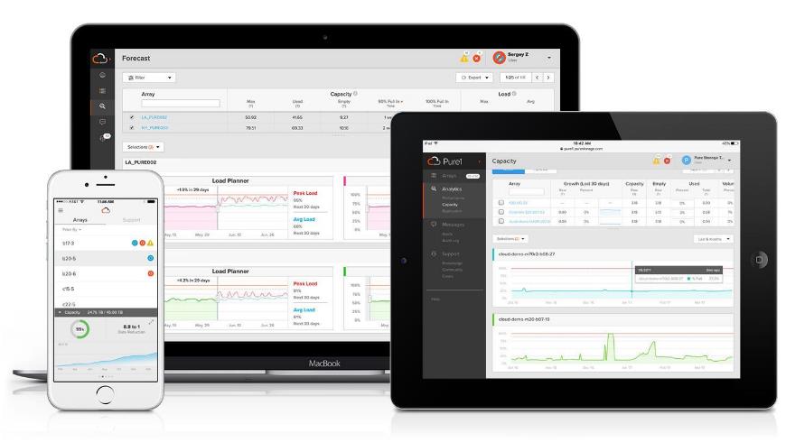
Pure1 Manage
Pure1 Manage is a SaaS-based offering that allows customers to manage their array from any browser or from the Pure1 Mobile App with nothing extra to purchase, deploy, or maintain. From a single dashboard, customers can manage all their arrays and have full storage health and performance visibility.
Pure1 Analyze
Pure1 Analyze delivers true performance forecasting, giving customers complete visibility into the performance and capacity needs of their arrays, now and in the future. Performance forecasting enables intelligent consolidation and workload optimization.
Pure1 Support
Pure Storage support team with the predictive intelligence of Pure1 Meta delivers unrivaled support that’s a key component in FlashArray 99.9999% availability. Some of the customer issues are identified and fixed without any customer intervention.
Pure1 META
The foundation of Pure1 services, Pure1 Meta is global intelligence built from a massive collection of storage array health and performance data. By continuously scanning call-home telemetry from Pure’s installed base, Pure1 Me-ta uses machine learning predictive analytics to help resolve potential issues, optimize workloads, and provide ac-curate forecasting. Meta is always expanding and refining what it knows about array performance and health.
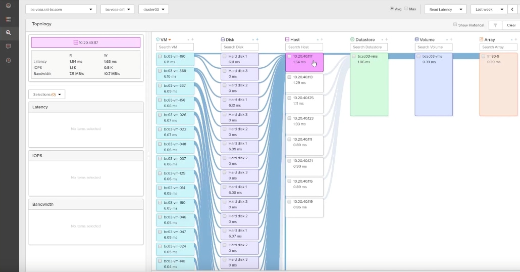
Pure1 VM Analytics
Pure1 helps you narrow down the troubleshooting steps in your virtualized environment. VM Analytics provides you with a visual representation of the IO path from the VM all the way through to the FlashArray. Other tools and features guide you through identifying where an issue might be occurring to help eliminate potential candidates for a problem.
VM Analytics doesn’t only help when there’s a problem. The visualization allows you to identify which volumes and arrays particular applications are running on. This brings the whole environment into a more manageable domain.
VMware vSphere is a virtualization platform for holistically managing large collections of infrastructures (resources including CPUs, storage, and networking) as a seamless, versatile, and dynamic operating environment. Unlike traditional operating systems that manage an individual machine, VMware vSphere aggregates the infrastructure of an entire data center to create a single powerhouse with resources that can be allocated quickly and dynamically to any application in need.
VMware vSphere 7.0 U3 has several improvements and simplifications including, but not limited to:
● vSphere Memory Monitoring and Remediation, and support for snapshots of PMem VMs: vSphere Memory Monitoring and Remediation collects data and provides visibility of performance statistics to help you determine if your application workload is regressed due to Memory Mode. vSphere 7.0 Update 3 also adds support for snapshots of PMem VMs.
● Improved interoperability between vCenter Server and ESXi versions: Starting with vSphere 7.0 Update 3, vCenter Server can manage ESXi hosts from the previous two major releases and any ESXi host from version 7.0 and 7.0 up-dates. For example, vCenter Server 7.0 Update 3 can manage ESXi hosts of versions 6.5, 6.7 and 7.0, all 7.0 update releases, including later than Update 3, and a mixture of hosts between major and update versions.
● New VMNIC tag for NVMe-over-RDMA (NVME/RoCEv2) storage traffic: ESXi 7.0 Update 3 adds a new VMNIC tag for NVMe-over-RDMA (NVMe/RoCEv2) storage traffic. This VMkernel port setting enables NVMe-over-RDMA traffic to be routed over the tagged interface. You can also use the ESXCLI command esxcli network ip interface tag add -i <interface name> -t NVMeRDMA to enable the NVMeRDMA VMNIC tag.
● NVMe over TCP support: vSphere 7.0 Update 3 extends the NVMe-oF suite with the NVMe over TCP storage proto-col to enable high performance and parallelism of NVMe devices over a wide deployment of TCP/IP networks.
● Micro-second level time accuracy for workloads: ESXi 7.0 Update 3 adds the hardware timestamp Precision Time Protocol (PTP) to enable micro-second level time accuracy. For more information, see Use PTP for Time and Date Synchronization of a Host.
For more information about VMware vSphere and its components, see: https://www.vmware.com/products/vsphere.html.
VMware vSphere vCenter
VMware vCenter Server provides unified management of all hosts and VMs from a single console and aggregates performance monitoring of clusters, hosts, and VMs. VMware vCenter Server gives administrators a deep insight into the status and configuration of compute clusters, hosts, VMs, storage, the guest OS, and other critical components of a virtual infrastructure. VMware vCenter manages the rich set of features available in a VMware vSphere environment.
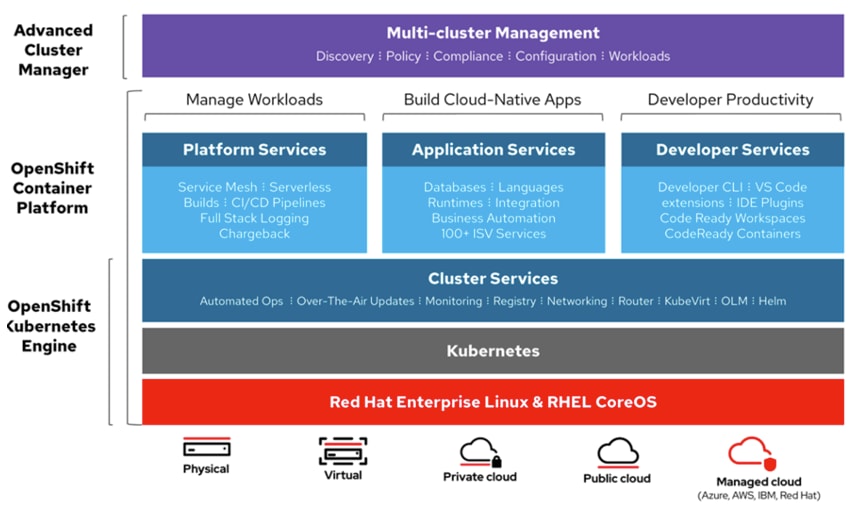
Red Hat OpenShift Container Platform
The Red Hat OpenShift Container Platform (OCP) is a container application platform that brings together CRI-0 and Kubernetes and provides an API and web interface to manage these services. CRI-O is an implementation of the Kubernetes CRI (Container Runtime Interface) to enable using Open Container Initiative (OCI) compatible runtimes. It is a lightweight alternative to using Docker as the runtime for Kubernetes.
OCP allows customers to create and manage containers. Containers are standalone processes that run within their own environment, independent of the operating system and the underlying infrastructure. OCP helps developing, deploying, and managing container-based applications. It provides a self-service platform to create, modify, and deploy applications on demand, thus enabling faster development and release life cycles. OCP has a microservices-based architecture of smaller, decoupled units that work together. It runs on top of a Kubernetes cluster, with data about the objects stored in etcd, a reliable clustered key-value store.
Kubernetes Infrastructure
Within Red Hat OpenShift Container Platform, Kubernetes manages containerized applications across a set of CRI-O runtime hosts and provides mechanisms for deployment, maintenance, and application-scaling. The CRI-O service packages, instantiates, and runs containerized applications.
A Kubernetes cluster consists of one or more masters and a set of worker nodes. This solution design includes HA functionality at the hardware as well as the software stack. A Kubernetes cluster is designed to run in HA mode with 3 control panel nodes and a minimum of 3 worker nodes to help ensure that the cluster has no single point of failure.
Red Hat Enterprise Linux CoreOS
Red Hat OpenShift Container Platform uses Red Hat Enterprise Linux CoreOS (RHCOS), a container-optimized operating system that combines some of the best features and functions of the Red Hat Enterprise Linux CoreOS and Red Hat Enterprise Linux Atomic Host operating systems. RHCOS is specifically designed for running containerized applications from Red Hat OpenShift Container Platform and works with new tools to provide fast installation, Operator-based management, and simplified upgrades.
RHCOS includes the following:
● Ignition, which OpenShift Container Platform uses as a first boot system configuration for initially bringing up and configuring machines.
● CRI-O, a Kubernetes native container runtime implementation that integrates closely with the operating system to deliver an efficient and optimized Kubernetes experience. CRI-O provides facilities for running, stopping, and restarting containers. It fully replaces the Docker Container Engine, which was used in OpenShift Container Platform 3.
● Kubelet, the primary node agent for Kubernetes that is responsible for launching and monitoring containers.
In the solution presented in this document, RHCOS was used on all control plane and worker nodes to support an automated RHOCP 4.9.10 deployment.
Portworx Enterprise by Pure Storage
Portworx is a data management solution that serves applications and deployments in Kubernetes clusters. Portworx is deployed natively within Kubernetes and extends the automation capabilities down into the infrastructure to eliminate all the complexities of managing data. Portworx provides simple and easy-to-consume StorageClasses that are usable by stateful applications in a Kubernetes cluster.
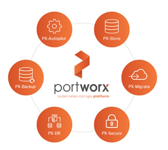
At the core of Portworx is PX-Store, a software-defined storage platform that works on practically any infrastructure, regardless of whether it is in a public cloud or on-premises. PX-Store is complemented by these modules:
● PX-Migrate: Allows applications to be easily migrated across clusters, racks, and clouds
● PX-Secure: Provides access controls and enables data encryption at a cluster, namespace, or persistent volume level
● PX-DR: A service that allows applications to have a zero RPO failover across data centers in a metro area as well as continuous backups across the WAN for even greater protection
● PX-Backup: A solution that allows enterprises to back up and restore the entire Kubernetes application, including data, app configuration, and Kubernetes objects, to any backup location—including S3, Azure Blob, and so on—with the click of a button.
● PX-Autopilot: A service that provides rules-based auto-scaling for persistent volumes and storage pools
PX-Store
PX-Store is a 100% software-defined storage solution that provides high levels of persistent volume density per block device per worker node. The key features of PX-Store include:
● Storage Virtualization: The storage made available to each worker node is effectively virtualized such that each worker node can host pods that use up to hundreds of thousands of persistent volumes per Kubernetes cluster. This benefits Kubernetes clusters deployed to the cloud, in that larger volumes or disks are often conducive to better performance.
● Storage-Aware Scheduling: Stork, a storage-aware scheduler, co-locates pods on worker nodes that host the persistent volume replicas associated with the same pods, resulting in reduced storage access latency.
● Storage Pooling for Performance-Based Quality-of-Service: PX-Store segregates storage into three distinct pools of storage based on performance: low, medium, and high. Applications can select storage based on performance by specifying one of these pools at the StorageClass level.
● Persistent Volume Replicas: You can specify a persistent volume replication factor at the StorageClass level. This enables the state to be highly available across the cluster, cloud regions, and Kubernetes-as-a-service platforms.
● Cloud Volumes: Cloud volumes enable storage to be provisioned from the underlying platform without the need to present storage to worker nodes. PX-Store running on most public cloud providers, VMware vSphere, or bare-metal with Pure Storage FlashArray have cloud volume capability. Cloud Drives enable elastic provisioning and scaling as workload needs change through automation and deep integrations.
● Automatic I/O Path Tuning: Portworx provides different I/O profiles for storage optimization based on the I/O traffic pattern. By default, Portworx automatically applies the most appropriate I/O profile for the data patterns it sees. It does this by continuously analyzing the I/O pattern of traffic in the background.
● Metadata Caching: High-performance devices can be assigned the role of journal devices to lower I/O latency when accessing metadata.
● Read- and Write-Through Caching: PX-Cache-enabled high-performance devices can be used for read- and write-through caching to enhance performance.
PX-Backup
Backup is essential for enterprise applications, serving as a core requirement for mission-critical production workloads. The risk to the enterprise is magnified for applications on Kubernetes where traditional, virtual machine (VM)-optimized data protection solutions simply don’t work. Protecting stateful applications like databases in highly dynamic environments calls for a purpose-built, Kubernetes-native backup solution.
Portworx PX-Backup solves these shortfalls and protects your applications’ data, application configuration, and Kubernetes objects with a single click at the Kubernetes pod, namespace, or cluster level. Enabling application-aware backup and fast recovery for even complex distributed applications, PX-Backup delivers true multi-cloud availability with key features, including:
● App-Consistent Backup and Restore: Easily protect and recover applications regardless of how they are initially deployed on, or rescheduled by, Kubernetes.
● Seamless Migration: Move a single Kubernetes application or an entire namespace between clusters.
● Compliance Management: Manage and enforce compliance and governance responsibilities with a single pane of glass for all your containerized applications.
● Streamlined Storage Integration: Back up and recover cloud volumes with storage providers including Amazon EBS, Google Persistent Disk, Azure Managed Disks, and CSI-enabled storage.
PX-DR
PX-DR extends the data protection included in PX-Store with zero RPO disaster recovery for data centers in a metropolitan area as well as continuous backups across the WAN for an even greater level of protection. PX-DR provides both synchronous and asynchronous replication, delivering key benefits, including:
● Zero Data Loss Disaster Recovery: PX-DR delivers zero RPO failover across data centers in metropolitan areas in addition to HA within a single data center. You can deploy applications between clouds in the same region and ensure application survivability.
● Continuous Global Backup: For applications that span a country—or the entire world—PX-DR also offers constant incremental backups to protect your mission-critical applications.
PX-Autopilot
PX-Autopilot allows enterprises to automate storage management to intelligently provision cloud storage only when needed and eliminate the problem of paying for storage when over-provisioned. PX-Autopilot delivers a number of benefits:
● Grow Storage Capacity On-Demand: Automate your applications’ growing storage demands while also minimizing disruptions. Set growth policies to automate cloud drive and Kubernetes integration to ensure each application’s storage needs are met without performance or availability degradations.
● Slash Storage Costs by Half: Intelligently provision cloud storage only when needed and eliminate the problem of paying for storage when over-provisioned instead of consumed. Scale at the individual volume or entire cluster level to save money and avoid application outages.
● Integrate with All Major Clouds, VMware, and Pure Storage FlashArray: PX-Autopilot natively integrates with AWS, Azure, and Google as well as Red Hat OpenShift, enabling you to achieve savings and increase automated agility across all your clouds.
Ansible is simple and powerful, allowing users to easily manage various physical devices within FlashStack including the provisioning of Cisco UCS servers, Cisco Nexus switches, Pure Storage FlashArray storage, and VMware vSphere. Using Ansible’s playbook-based automation is easy and integrates into your current provisioning infrastructure. Customers can use the Ansible playbooks that are made available in the GitHub repository for automating the FlashStack deployment.
GitHub repository is available here: https://github.com/ucs-compute-solutions/FlashStack_IMM_Ansible
Cisco Intersight Assist Device Connector for VMware vCenter and Pure Storage FlashArray
Cisco Intersight integrates with VMware vCenter and Pure Storage FlashArray as follows:
● Cisco Intersight uses the device connector running within Cisco Intersight Assist virtual appliance to communicate with the VMware vCenter.
● Cisco Intersight uses the device connector running within a Cisco Intersight Assist virtual appliance to integrate with all Pure Storage FlashArray /models. The newest version 1.1 of Pure Storage integration to Cisco Intersight intro-duces support for REST API 2.x for FlashArray products (running Purity//FA 6.0.3 or later), along with User Agent support (for telemetry). Cisco Intersight Cloud Orchestrator now has new storage tasks for adding/removing a Pure Storage snapshot and cloning a Pure Storage volume from snapshot.
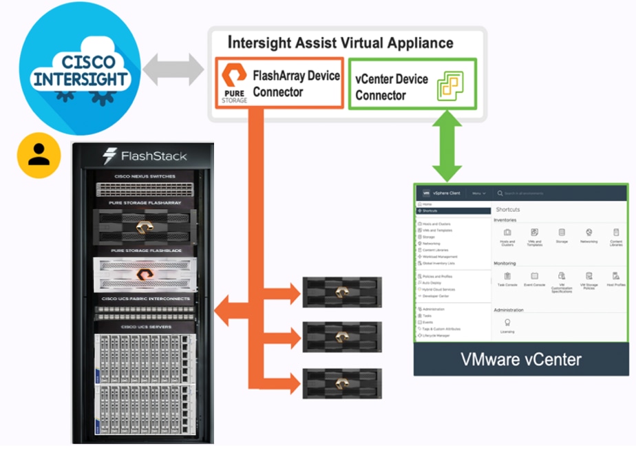
The device connector provides a safe way for connected targets to send information and receive control instructions from the Cisco Intersight portal using a secure Internet connection. The integration brings the full value and simplicity of Cisco Intersight infrastructure management service to VMware hypervisor and FlashArray storage environments. The integration architecture enables FlashStack customers to use new management capabilities with no compromise in their existing VMware or FlashArray operations. IT users will be able to manage heterogeneous infrastructure from a centralized Cisco Intersight portal. At the same time, the IT staff can continue to use VMware vCenter and the Pure Storage dashboard for comprehensive analysis, diagnostics, and reporting of virtual and storage environments.
FlashStack for Microsoft SQL Server Database Containers
The following are a few unique capabilities that the FlashStack solution brings for critical and latency-sensitive database deployments:
● Containerized Microsoft SQL Server database deployments: Containers, in general, offer lot of advantages such as portability, agility, faster provisioning, and auto scaling fueling DevOps deployment models and CI/CD pipelines. These advantages have led to a continuous demand for enterprise grade containerized operational databases with full support from database vendors. Microsoft SQL Server is a popular relational database with enterprise grade features, and it can be containerized and deployed in any Kubernetes environment. This FlashStack solution stitches the required hardware and software components such as Cisco UCS, Pure Storage, VMware vSphere, Red Hat OCP, Portworx Enterprise, etc., and provides a highly available and high performing robust platform for deploying enterprise grade containerized databases.
● Highly available and Persistent Storage: Databases are meant to provide a persistent data service and needs to be highly available due to various types and nature of the data they store. Therefore, the underlying platform must provide persistent and highly available storage services for database deployments. Portworx Enterprise is an enterprise storage and data management platform that meets all the storage requirements of database deployments on Kubernetes. Portworx offers many features and deployment options including single site deployment and multi-site deployment with Synchronous and Asynchronous replication for the high availability and data protection.
● Blazing IO Performance using NVMe over Fabric (NVMe-oF) implementation: This solution implements NVMe over Fabric (using Fibre Channel as transfer medium) protocol specification for providing faster storage access between servers that hosts applications and target storage device. This solution uses Pure Storage FlashArray//XL which is the world’s first 100% native NVMe storage solution for Tier 0 and Tier 1 block storage applications. The database container deployments, which are traditionally IO sensitive, can take full advantage of faster storage access and can deliver consistent performance required for enterprise applications.
● Stateless and Programmable Computing Platform: Cisco UCS provides a stateless and programmable computing platform envisioning servers as resources whose identity, configuration, and connectivity could be managed through software rather than the tedious, time-consuming, error-prone manual processes of the day. Cisco UCS service profiles which consist of critical server information like network, storage, boot order, VLANs, and so on, can be dynamically created and associated with any physical server within minutes rather than hours. It facilitates rapid bare-metal provisioning and replacement of failed servers by simply migrating service profiles among servers there by greatly reducing the application downtime hosted on these servers. The Boot from SAN option further takes full advantage of Cisco UCS stateless computing and enables faster physical server recovery by simply migrating service profiles between the servers.
● Cloud based centralized Infrastructure management: Cisco Intersight cloud operations platform provides the capability to handle full lifecycle management of on-premises infrastructure, remote, branch, and edge locations, and the public cloud. From a single cloud-based interface, we can consistently manage the entire infrastructure including Pure Storage and vSphere Cluster, no matter where it resides.
Solution Design
This chapter contains the following:
● Pure Storage FlashArray – Storage Design
● VMware vSphere – ESXi Design
● Red Hat OpenShift Container Platform Logical Network Design
This FlashStack solution for Red Hat OpenShift Platform provides end-to-end architecture with Cisco and Pure Storage technologies that demonstrate support for OCP workloads with high availability using redundancy at all the levels of hardware and software stack. The architecture consists of a Red Hat OpenShift cluster deployed on virtual machines that run on highly available VMware vSphere cluster deployed on Cisco UCS platform comprising of a Cisco UCS 5908 chassis with Cisco UCS X210c blade servers and Cisco UCS 6400 Fabric Interconnects. The vSphere cluster is connected to Pure Storage FlashArray//XL170 array using Cisco MDS Fibre Channel switches. This architecture uses NVMe-FC protocol for faster data access and traditional SCSI-FC for booting Cisco UCS X210c blades from Pure Storage. Cisco Nexus 9000 series switches are used for networking elements.
The Cisco Intersight cloud-management platform is utilized to configure and manage the infrastructure. The solution requirements and design details are explained in this section.
This section explains the key design requirements and prerequisites for delivering this solution.
The FlashStack solution for OCP on vSphere cluster is closely aligns with NX-OS based FlashStack system and meets the following general design requirements:
● Resilient design across all layers of the infrastructure with no single points of failure
● Scalable design with the flexibility to add compute and storage capacity or network bandwidth as needed
● Modular design that can be replicated to expand and grow as the needs of the business grow
● Flexible design that can support different models of various components with ease
● Simplified design with ability to integrate and automate with external automation tools
● Cloud-enabled design which can be configured, managed, and orchestrated from the cloud using GUI or APIs
For Red Hat OCP 4 integration into a traditional vSphere based FlashStack systems, the following specific design considerations also be observed:
● High Availability of master nodes with a minimum of 3 master nodes deployed.
● A minimum of 3 worker nodes (required Portworx deployment) with ability to increase the nodes as the load requirements increase.
● Automating the FlashStack infrastructure deployment and OCP installation by utilizing Ansible Playbooks to simplify the installation and reduce the deployment time.
● Present persistent storage (volumes) to the containerized applications by utilizing the Portworx storage provisioning platform.
● Dedicated Cisco UCS vNICs for different traffic needs with Cisco UCS Fabric Failover for high availability.
FlashStack with Cisco UCS X-Series supports both IP-based and Fibre Channel based storage access design. This solution is validated using Fibre channel-based storage access design. Pure Storage FlashArray and Cisco UCS X-Series are connected using Cisco MDS 9132T switches for storage access. The Cisco UCS X210c server blades are configured with two traditional vHBAs to access the storage volumes and configured to boot from SAN storage. Blade servers are also configured with nvme-fc capable vHBAs for accessing the storage volumes using NVMe over Fabrics (NVME-oF) using Fibre Channel media at lower data access latencies. The physical connectivity details FC designs are explained below.
FC-based Storage Access
The physical topology for the FlashStack for FC connectivity is shown in Figure 17.
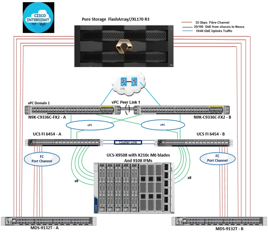
To validate the FC-based storage access in a FlashStack configuration, the components are set up as follows:
● Cisco UCS 6454 Fabric Interconnects provide the chassis and network connectivity.
● The Cisco UCS X9508 Chassis connects to fabric interconnects using Cisco UCSX 9108-25G Intelligent Fabric Modules (IFMs), where four 25 Gigabit Ethernet ports are used on each IFM to connect to the appropriate FI.
● Cisco UCS X210c M6 Compute Nodes contain fourth-generation Cisco UCS 14425 virtual interface cards.
● Cisco Nexus switches in Cisco NX-OS mode provide the switching fabric.
● Cisco UCS 6454 Fabric Interconnect 100 Gigabit Ethernet uplink ports connect to Cisco Nexus 93360YC-FX2 Switches in a vPC configuration.
● Cisco UCS 6454 Fabric Interconnects are connected to the Cisco MDS 9132T switches using 32-Gbps Fibre Channel connections configured as a port channel for SAN connectivity
● The Pure Storage FlashArray//XL170 connects to the Cisco MDS 9132T switches using 32-Gbps Fibre Channel connections for SAN connectivity.
● VMware 7.0 U3 ESXi software is installed on Cisco UCS X210c M6 Compute Nodes to validate the infrastructure.
Table 3 lists the hardware and software components along with image versions used in this solution.
Table 3. Hardware and Software Components Specifications
| Component |
Software |
|
| Network |
Cisco Nexus9000 C93360YC-FX2 |
10.2(3) |
| Cisco MDS 9132T |
8.4(2c) |
|
| Compute |
Cisco UCS Fabric Interconnect 6454 |
9.3(5)I42(2c) |
| Cisco UCS UCSX 9108-25G IFM |
4.2(1f) |
|
| Cisco UCS X210C Compute Nodes |
5.0(2d) |
|
| Cisco UCS VIC 14425 installed on X210c |
5.2(2d) |
|
| VMware ESXi |
7.0 U3 |
|
| Cisco VIC ENIC Driver for ESXi |
1.0.42.0 |
|
| Cisco VIC FNIC Driver for ESXi |
5.0.0.34 |
|
| VMware vCenter Appliance |
7.0 U3 |
|
| Cisco Intersight Assist Virtual Appliance |
1.0.9-342 |
|
| Storage |
Pure Storage FlashArray//XL170 |
6.3.3 |
| Pure Storage VASA Provider |
3.5 |
|
| Pure Storage vSphere Plugin |
5.0.0 |
|
| Portworx Enterprise Container Storage Provisioning Platform |
2.12 |
|
| Container Platform |
Red Hat OpenShift |
4.10.9 |
| Database Containers |
Microsoft SQL Server |
2019 RTM-CU18 |
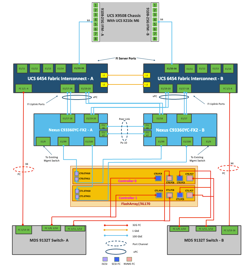
FlashStack Cabling
The information in this section is provided as a reference for cabling the physical equipment in a FlashStack environment. To simplify cabling requirements, a cabling diagram was used. Figure 18 details the cable connections used in the validation lab for FlashStack topology based on the Cisco UCS 6454 fabric interconnect.
This document assumes that out-of-band management ports are plugged into an existing management infrastructure at the deployment site. These interfaces will be used in various configuration steps.
A total of eight 32Gb links connect the MDS switches to the Pure FlashArray//XL170 controllers, four of these have been used for scsi-fc and the other four to support nvme-fc.
The four 25Gb links on each Fabric Interconnect connect the Cisco UCS Fabric Interconnects to the Cisco Nexus Switches with vPC configured. Optionally two 100Gb ports on each Fabric Interconnect can be connected to the pair of Cisco the Nexus Switches in vPC mode.
Additional 1Gb management connections will be needed for an out-of-band network switch that sits apart from the FlashStack infrastructure. Each Cisco UCS fabric interconnect and Cisco Nexus switch is connected to the out-of-band network switch, and each FlashArray controller has a connection to the out-of-band network switch. Layer 3 network connectivity is required between the Out-of-Band (OOB) and In-Band (IB) Management Subnets.
FlashStack Cabling with Cisco UCS 6454 Fabric Interconnect
VLAN Configuration
Table 4 lists the VLANs configured for setting up the FlashStack environment along with their usage.
Table 4. VLAN Usage
| VLAN ID |
Name |
Usage |
| 2 |
Native-VLAN |
Use VLAN 3 as native VLAN instead of default VLAN (1). |
| 1030 |
OOB-MGMT-VLAN |
Out-of-band management VLAN to connect management ports for various devices |
| 1031 |
IB-MGMT-VLAN |
In-band management VLAN utilized for all in-band management connectivity - for example, ESXi hosts, VM management, and so on. |
| 1032 |
VM-Traffic |
VM data traffic VLAN |
| 3319 |
vMotion |
VMware vMotion traffic |
Table 5 lists the VSANs configured for setting up the FlashStack environment along with their usage.
| VSAN ID |
Name |
Fabric |
Usage |
| 103 |
VSAN-A-103 |
A |
VSAN ID for storage traffic via Fabric-A |
| 104 |
VSAN-B-104 |
B |
VSAN ID for storage traffic via Fabric-B |
In FlashStack deployments, each Cisco UCS server equipped with a Cisco Virtual Interface Card (VIC) is configured for multiple virtual Network Interfaces (vNICs), which appear as standards-compliant PCIe endpoints to the OS. The end-to-end logical connectivity including VLAN/VSAN usage between the server profile for an ESXi host and the storage configuration on Pure Storage FlashArray is described below.
Logical Topology for FC-based Storage Access
Figure 19 illustrates the end-to-end connectivity design for FC-based storage access.
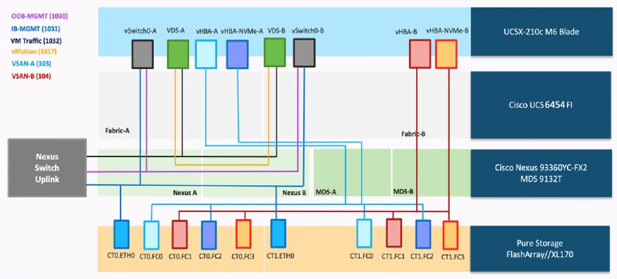
Each ESXi server profile supports:
● Managing the ESXi hosts using a common management segment
● Diskless SAN boot using FC with persistent operating system installation for true stateless computing
● Four vNICs where:
◦ Two redundant vNICs (vSwitch0-A and vSwitch0-B) carry management traffic. The MTU value for these vNICs is set as a Jumbo MTU (9000).
◦ The vSphere Distributed switch uses two redundant vNICs (VDS-A and VDS-B) to carry VMware vMotion traffic and customer applications data traffic. The MTU for the vNICs is set to Jumbo MTU (9000).
● Four vHBAs where:
◦ One vHBA (vHBA-A) defined on Fabric A provides access to the SAN-A path (FC Initiator)
◦ One vHBA (vHBA-B) defined on Fabric B provides access to the SAN-B path (FC Initiator)
◦ One vHBA (vHBA-NVMe-A) defined on Fabric A provides access to the SAN-A path for NVMe over Fabric traffic (FC-NVMe Initiator)
◦ One vHBA (vHBA-NVMe-B) defined on Fabric B provides access to the SAN-B path for NVMe over Fabric traffic (FC-NVMe Initiator)
Pure Storage FlashArray – Storage Design
To set up Pure Storage FlashArray, you must configure the following items:
● Volumes
◦ ESXi boot LUNs: These LUNs enable ESXi host boot from SAN functionality using Fibre Channel.
◦ The vSphere environment: vSphere uses the infrastructure datastore(s) to store the virtual machines. These volumes can be exposed to the ESXi hosts using traditional Fibre Channel protocol.
◦ Volumes for Application data storage: These volumes are exposed to the ESXi hosts using fc-nvme adapters which provides low latency access to the storage. In this solution, one big volume is created and exposed to the vSphere Cluster using fc-nvme adapter for storing Portworx volumes which are used by Microsoft SQL Server database pods for storing the database files.
● Hosts
◦ All FlashArray ESXi hosts are defined using the FC WWNs (scsi-fc based initiators) and NQNs (fc-nvme based initiators).
◦ Add every active initiator for a given ESXi host.
● Host groups
◦ All ESXi hosts in a VMware cluster are part of the host group.
◦ Host groups are used to mount VM infrastructure application storage datastores in the VMware environment so that all the ESXi hosts that part of Host Group will get access storage volumes.
The volumes, interfaces, and VLAN/VSAN details are shown in Figure 20 for Fibre Channel connectivity.
Along with SCSI-FC, this solution implements NVMe using the FC-NVMe protocol over a SAN built using Cisco MDS switches. NVMe initiators consisting of Cisco UCS X210C servers installed with Cisco 14425 VIC adapters can access Pure FlashArray NVMe targets over Fibre Channel.
Each port on the Pure FlashArray can be configured as traditional scsi-fc port or as a nvme-fc port to support NVMe end-to-end via Fibre Channel from the host to storage array. Note that a given FC port is either going to be SCSI or NVMe, not both.
Two ports on each Pure FlashArray controllers are configured as SCSI ports and the other two are configured as NVMe ports in this design validation.
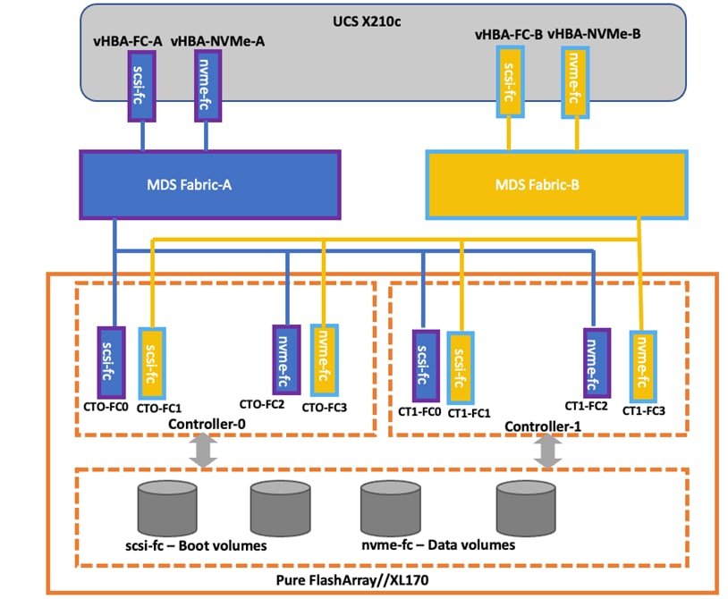
Cisco UCS provides a unified fabric that is an architectural approach delivering flexibility, scalability, intelligence, and simplicity. This flexibility allows Cisco UCS to readily support new technologies such as FC-NVMe seamlessly. In a Cisco UCS service profile, both standard Fibre Channel and FC-NVMe vHBAs can be created.
Both Fibre Channel and FC-NVMe vHBAs can exist in a Cisco UCS service profile on a single server. In the lab validation for this document, four vHBAs (one FC-NVME initiator on each Fibre Channel fabric and one Fibre Channel initiator on each Fibre Channel fabric) were created in each service profile. Each vHBA, regardless of type, was automatically assigned a worldwide node name (WWNN) and a worldwide port name (WWPN). The Cisco UCS fabric interconnects were in Fibre Channel end-host mode (NPV mode) and uplinked through a SAN port channel to the Cisco MDS 9132T switches in NPV mode. Zoning in the Cisco MDS 9132T switches connected the vHBAs to storage targets for both FC-NVMe and Fibre Channel. Single-initiator, multiple-target zones were used for both FCP and FC-NVMe.
The ESXi automatically connects to Pure FlashArray NVMe subsystem and discovers all shared NVMe storage devices that it can reach once the SAN zoning on MDS switches, and the configuration of host/host groups and volumes is completed on the Pure FlashArray.
For the FlashArray VMware best practices user guide, go to: https://support.purestorage.com/Solutions/VMware_Platform_Guide/User_Guides_for_VMware_Solutions/FlashArray_VMware_Best_Practices_User_Guide.
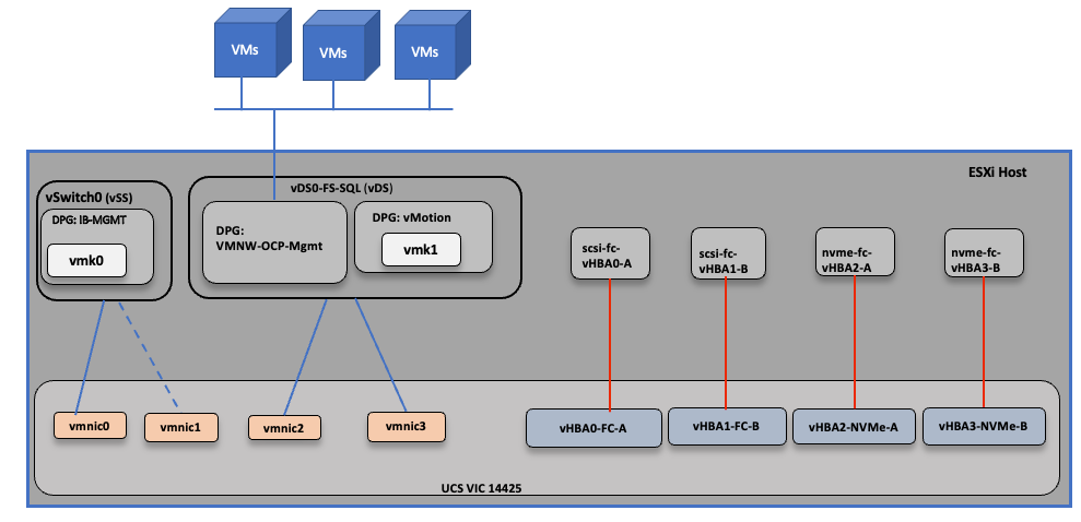
VMware vSphere – ESXi Networking Design
Multiple vNICs and vHBAs are created for the ESXi hosts using the Cisco Intersight server profile and are then assigned to specific virtual and distributed switches. The vNIC and vHBA distribution for the ESXi hosts is as follows:
● Two vNICs (one on each fabric) for vSwitch0 to support core services such as management traffic.
● Two vNICs (one on each fabric) for vSphere Virtual Distributed Switch (VDS) to support customer application data traffic and vMotion traffic.
● One vHBA each for Fabric-A and Fabric-B for FC stateless boot.
● One vHBA each for Fabric-A and Fabric-B for storage access using FC-NVMe.
Figure 21 shows the ESXi vNIC and vHBAs configurations in detail.
Red Hat OpenShift Container Platform Logical Network Design
OpenShift Container Platform uses a software-defined networking (SDN) approach to provide a unified cluster network that enables communication between pods across the OpenShift Container Platform cluster. This pod network is established and maintained by the OpenShift SDN, which configures an overlay network using Open vSwitch (OVS). The default OpenShift SDN solution is built on top of Open vSwitch (OVS). With OpenShift, the cluster admin can choose to deploy with one of the OpenShift native SDN plug-ins or they can opt to deploy the cluster using a third-party SDN from the supported ecosystem such as Cisco ACI. For this solution, the OpenShift native SDN plug-in (OVN-Kubernetes) is used. The OVN-Kubernetes default Container Network Interface (CNI) network provider implements the following features:
● Uses OVN (Open Virtual Network) to manage network traffic flows. OVN is a community developed, vendor agnostic network virtualization solution.
● Implements Kubernetes network policy support, including ingress and egress rules.
● Uses the Geneve (Generic Network Virtualization Encapsulation) protocol rather than VXLAN to create an overlay network between nodes.
Figure 22 illustrates the OCP network implementation with in a OCP master or worker VM hosted on ESXi host.
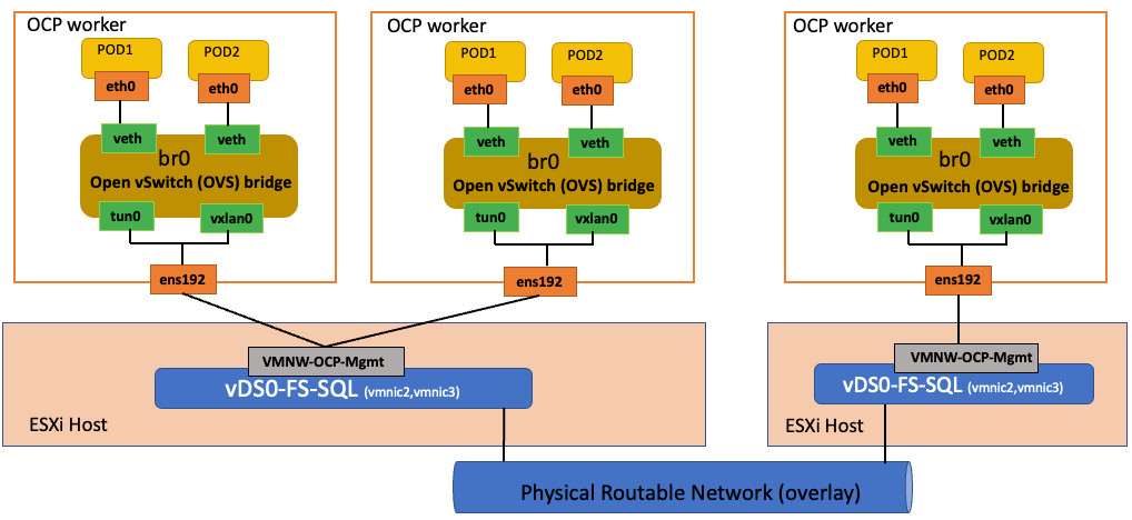
In addition to the native ethernet device of the node, ens192, OpenShift SDN creates and configures three network devices on each node:
● br0: The OVS bridge device that pod containers will be attached to. OpenShift SDN also configures a set of non-subnet-specific flow rules on this bridge.
● tun0 (port 2 on br0): an OVS internal port (port 2 on br0). This gets assigned the cluster subnet gateway address and is used for external network access. OpenShift SDN configures netfilter and routing rules to enable access from the cluster subnet to the external network via NAT.
● vxlan_sys_4789: The OVS VXLAN device (port 1 on br0), which provides access to containers on remote nodes. Referred to as vxlan0 in the OVS rules.
Now suppose first that pod A and pod B are on the same OCP worker node. Then the flow of packets from pod A to pod B is as follows:
eth0 (in A’s netns) → vethA → br0 → vethB → eth0 (in B’s netns)
Next, assume that pod A and pod B on two different OCP worker nodes 1 and 2 running on two different ESXi hosts 1 and 2. Then the flow of packets from pod A to pod B is as follows.
eth0 (in A’s netns) → vethA → br0 → vxlan0 → ens192(worker 1) → vDSO-FS-SQL (ESXi host1) → Physical Network → vDSO-FS-SQL (ESXi host2) → end192(worker 2) → vxlan0 → br0 → vethB → eth0 (in B’s netns)
Finally, if pod A connects to an external host, the traffic looks like:
eth0 (in A’s netns) → vethA → br0 → tun0 → (NAT) → ens192 → vDSO-FS-SQL → Internet
In addition to the communication amongst the pods, more often, these pods need to be accessed by clients from outside the OpenShift cluster to consume the services they provide. Incoming access to the applications and services hosted by the running pods can be accomplished in multiple ways:
● NodePort. Apps exposed with a NodePort service use a TCP port in the range of 30000 - 32767 and an internal cluster IP address from the service network is assigned to the service. To access the service from outside the cluster, you use the public facing IP address of any worker node via the URL in the format <IP_address>:<nodeport>. NodePorts are ideal for testing application or service access for a short amount of time.
● OpenShift Routes. A router is deployed by default to the cluster, which enable routes to be created for external access. When a Route object is created on OpenShift, it gets picked up by the built-in HAProxy load balancer in order to expose the requested service and make it externally available. The router uses the service selector to find the service and the endpoints that back the service. You can configure the service selector to direct traffic through one route to multiple services.
● Ingress. An open-source Kubernetes implementation of OpenShift Route which performs similar functions. Apps are exposed via the OpenShift Ingress Controller, which is also an HAProxy load balancing service managed by the Ingress Operator. Using Ingress may be desirable when deploying pods across a variety of clusters running OpenShift and generic Kubernetes, whereas OpenShift Routes may be preferred when all clusters would run only OpenShift.
● Service Mesh. A distributed microservices architecture based on the open-source Istio project. You add Red Hat OpenShift Service Mesh support to services by deploying a special sidecar proxy to relevant services in the mesh that intercepts all network communication between microservices. External access is attained via Ingress and Egress gateways that manage traffic entering and leaving the service mesh.
Deployment of Hardware and Software
This chapter contains the following:
● Hardware and Software Revisions
● Cisco Nexus Switch Configuration
● Cisco MDS Switch Configuration
● Pure Storage FlashArray//XL170 Configuration
● Cisco UCS Server Configuration using Cisco Intersight (IMM mode)
● VMware vSphere ESXi Host Configuration
● Red Hat OpenShift Container Platform Deployment
● Portworx Enterprise Installation on OCP Cluster Running on vSphere Cluster
● Install Portworx Operator from OCP OperatorHub
● Deploy Microsoft SQL Server Database Pods using Portworx Volumes
This chapter describes the specific configurations and recommendations that are important for running FlashStack Datacenter for SQL Server workloads. For a detailed step-by-step deployment guide to configure the network, compute, and storage stacks of the FlashStack solutions, refer to the base infrastructure CVD here: https://www.cisco.com/c/en/us/td/docs/unified_computing/ucs/UCS_CVDs/flashstack_vsi_vmware70_ucsx.html
Hardware and Software Revisions
Table 3 lists the hardware and software versions used during solution validation. It is important to note that the validated FlashStack solution explained in this document adheres to Cisco, Pure Storage, and VMware interoperability matrix to determine support for various software and driver versions. You should use the same interoperability matrix to determine support for components that are different from the current validated design.
Click the following links for more information:
● Pure Storage Interoperability Matrix. Note, this interoperability list will require a support login form Pure: https://support.purestorage.com/FlashArray/Getting_Started/Compatibility_Matrix
● Pure Storage FlashStack Compatibility Matrix. Note, this interoperability list will require a support login from Pure: https://support.purestorage.com/FlashStack/Product_Information/FlashStack_Compatibility_Matrix
● Cisco UCS Hardware and Software Interoperability Tool: http://www.cisco.com/web/techdoc/ucs/interoperability/matrix/matrix.html
● VMware Compatibility Guide: http://www.vmware.com/resources/compatibility/search.php
Cisco Nexus Switch Configuration
On each Cisco Nexus Switch, required VLANs, Port Channels, vPC Domain and vPC-Peer links need to be done. These configurations, except the Ethernet interface numbers and VLAN numbers, are standard and no different than what is explained in the base infrastructure CVD. Please refer to the Cisco Nexus switch configuration in the base infrastructure CVD here: https://www.cisco.com/c/en/us/td/docs/unified_computing/ucs/UCS_CVDs/flashstack_vsi_vmware70_ucsx.html#NetworkSwitchConfiguration
Cisco MDS Switch Configuration
The Pure Storage FlashArray//XL170 array is connected to a pair of Cisco MDS switches to provide storage access to the Cisco UCS servers over Fibre Channel network. The Cisco UCS fabric interconnects were in Fibre Channel end-host mode (NPV mode) and uplinked through a SAN port channel to the Cisco MDS 9132T switches in NPV mode. Zoning in the Cisco MDS 9132T switches connected the vHBAs to storage targets for both FC-NVMe and Fibre Channel. Single-initiator, multiple-target zones were used for both FCP and FC-NVMe. These configurations, except the fibre channel interface numbers and VSAN numbers, are standard and no different than what is covered in the base infrastructure CVD. Refer to the Cisco MDS switch configuration in the base infrastructure CVD here: https://www.cisco.com/c/en/us/td/docs/unified_computing/ucs/UCS_CVDs/flashstack_vsi_vmware70_ucsx.html#SANSwitchConfiguration
Pure Storage FlashArray//XL170 Configuration
The Pure Storage configuration includes the following steps.
● Initial Pure Storage FlashArray Configuration
● Host Port identification, Host registration using WWNs for fc initiators and NQNs for fc-nvme initiators,
● Host Group creation
● Mapping boot volume to the hosts registered using WWNs and application Volume mapping for the hosts registered with NQNs
The Pure Storage FlashArray//XL170 configuration is a standard activity. For detailed steps to configure a Pure Storage FlashArray, go to: https://www.cisco.com/c/en/us/td/docs/unified_computing/ucs/UCS_CVDs/flashstack_vsi_vmware70_ucsx.html#_Toc97052007
For this solution, each controller of the Pure Storage FlashArray//XL170 array is connected to a pair of Cisco MDS switches in a redundant fashion to the MDS switches. On each controller, two FC interfaces with traditional scsi-fc capabilities are used for providing access to the esxi boot volumes and other infrastructure related volumes. Additionally, two FC ports with nvme-fc capabilities are used for providing access to the volumes for Portworx storage.
Figure 23 shows the four FC interfaces on each controller of FlashArray//XL170 used for this solution.
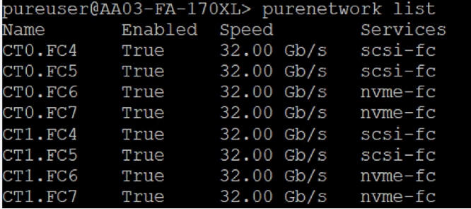
Cisco UCS Server Configuration using Cisco Intersight (IMM mode)
This section provides more details on the specific Cisco UCS polices and settings used for configuring Cisco UCS X210c blade server for hosting critical Microsoft SQL Server database container in vSphere based Red Hat OCP cluster. The Cisco UCS X210c blades installed in the Cisco UCS X9509 chassis and are connected to a pair of Cisco UCS 6454 Fabric Interconnects. The Cisco UCS fabric interconnects are managed by Intersight (IMM mode).
It is important to use right network and storage adapter policies for low latency and better storage bandwidth as the underlying Cisco VIC resources are shared various types of traffics such as Application management traffic hosted on the OCP cluster, application storage access, ESXi host management, vMotion, and so on.
LAN Connectivity Polices
The following vNICs are defined in a LAN connectivity policy to derive the vNICs for the ESXi host networking. The LAN connectivity policy is then used in Server profiles template to derive the Server profile.
● 00-vSwitch0-A: Is used for ESXi host management traffic via Fabric A
● 01-vSwitch0-B: Is used for ESXi host management traffic via Fabric B
● 02-vDS0-A: Is used for application management traffic and vMotion traffic via Fabric A
● 03-vDS0-B: Is used for application management traffic and vMotion traffic via Fabric B
Table 6 lists additional configuration details of the vNICs used in this reference architecture.
| vNIC Name |
00-vSwitch0-A |
01-vSwitch0-B |
02-vDS0-A |
03-vDS0-B |
| Slot ID |
MLOM |
MLOM |
MLOM |
MLOM |
| PCI Link |
0 |
0 |
0 |
0 |
| Switch ID |
A |
B |
A |
B |
| PCI Order |
0 |
1 |
2 |
3 |
| Fabric Failover |
Disabled |
Disabled |
Disabled |
Disabled |
| Network Group Policy (list of allowed VLANs and Native VLAN) |
1031 & 2 |
1031 & 2 |
1031, 3319 & 2 |
1031, 3319 & 2 |
| Network Control Policy (CDP, LLDP) |
CDP Enabled LLDP Enabled |
CDP Enabled LLDP Enabled |
CDP Enabled LLDP Enabled |
CDP Enabled LLDP Enabled |
| QoS & MTU |
Best Effort & 9000 |
Best Effort & 9000 |
Best Effort & 9000 |
Best Effort & 9000 |
| Ethernet Adapter Policy |
Default VMWare Adapter |
Default VMWare Adapter |
VMware-High-Traffic |
VMware-High-Traffic |
Note: Ensure the ports on the upstream Nexus switches are appropriately configured with MTU and VLANs for end-to-end consistent configuration.
Note: For simplified deployment, same VLAN 1031 is used for both ESXi host management and OCP Virtual Machine management traffic. VLAN 3319 is used for vMotion traffic.
Ethernet Adapter Policy
The Ethernet adapter policy allows the administrator to configure the capabilities of a vNIC, such as the number of rings, ring sizes, and offload enablement and disablement. In this solution, the vNIC 02-vDS0-A and 03-vDS0-B carry the OCP management traffic as well as the pod cluster network traffic. Therefore it is recommended to use the Adapter policy with higher Receive, Transmit and Completion queues. The following figure shows the Adapter policy used for vNICs 02-vDS0-A and 03-vDS0-B.
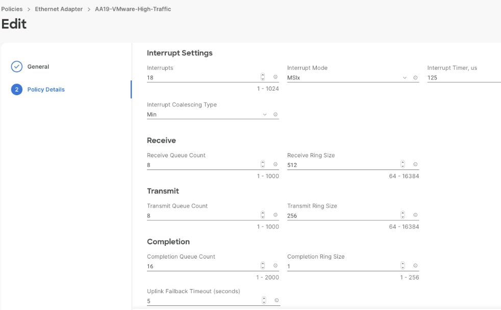
FC SAN Configuration
Cisco UCS 6454 Fabric Interconnects allows us to configure the first sixteen port as unified ports to carry the Fibre channel traffic. These ports are to be configured in the multiples of four. For this validation, first four ports are configured as unified ports on each Fabric Interconnect. The other ports (5 to 16) are unused, and they can be used for future use. The first four ports on Fabric Interconnect A are connected to the Cisco MDS Fibre Channel Switch A and forms a Fibre Channel port Channel. The storage traffic originated from the Cisco UCS X210c blades via Fabric Interconnect A is isolated using the vSAN ID 103. Similarly, the first ports on Fabric Interconnect B are connected to the Cisco MDS Fibre Channel Switch B and forms a Fibre Channel port Channel. The storage traffic originated from Cisco UCS X210c blades via Fabric Interconnect B is isolated using the vSAN ID 104.
Figure 25 shows the unified Port configuration on Fabric Interconnect A.
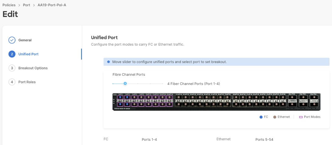
SAN Connectivity Policy
The following vHBAs defined in a SAN connectivity policy for the Pure storage connectivity of the ESXi host. The SAN connectivity policy is used in the Server profile template to derive the Server profile and the server profile is associated to a Cisco UCS X210c blade:
● vHBA0-FC-A: This vHBA is used for connecting and booting ESXi host from the Pure Storage over traditional scsi-fc via fabric A.
● vHBA1-FC-B: This vHBA is used for connecting and booting ESXi host from the Pure Storage over traditional scsi-fc via fabric B.
● vHBA2-NVMe-A: This vHBA is used for accessing the Pure storage volumes exposed over nvme-fc adapters with lowest possible IO latencies via fabric A.
● vHBA3-NVMe-B: This vHBA is used for accessing the Pure storage volumes exposed over nvme-fc adapters with lowest possible IO latencies via fabric B.
Table 7 lists additional configuration details of the vHBAs used in this reference architecture.
Table 7. vNICs and their corresponding settings used for this solution
| vHBA Name |
vHBA0-FC-A |
vHBA1-FC-B |
vHBA2-NVMe-A |
vHBA3-NVMe-B |
| vHBA Type |
fc-initiator |
fc-initiator |
fc-nvme-initiator |
fc-nvme-initiator |
| Slot ID |
MLOM |
MLOM |
MLOM |
MLOM |
| PCI Link |
0 |
0 |
0 |
0 |
| Switch ID |
A |
B |
A |
B |
| PCI Order |
4 |
5 |
6 |
7 |
| Persistent LUN Binding |
Enabled |
Enabled |
Enabled |
Enabled |
| Fibre Channel Network (vSAN ID) |
103 |
104 |
103 |
104 |
| QoS |
Rate Limit:0 Class of Service: 3 |
Rate Limit:0 Class of Service: 3 |
Rate Limit:0 Class of Service: 3 |
Rate Limit:0 Class of Service: 3 |
| Fibre Channel Adapter Policy |
Default Policy: initiator |
Default Policy: initiator |
Default Policy: FCNVMeinitiator |
Default Policy: FCNVMeinitiator |
Note: Ensure the Fibre Channel ports on the Cisco MDS switches are appropriately configured with correct VSAN ID and Zones for end-to-end consistent configuration.
Fibre Channel Adapter Policy
The FC adapter policy allows the administrator to configure various Fibre Channel related settings for the vHBAs, such as the IO Throttle Count, LUN Queue Depth, Receive and transmit Ring sizes. vHBA0-FC-A and vHBA1-FC-B are configured to use “initiator” policy while vHBA2-NVMe-A and vHBA3-NVMe-B are configured to use FCNVMeinitiator policy. The first two vHBAs carry the ESXi storage traffic (boot traffic) while the last two fc-nvme vHBAs carry the SQL Server database container storage traffic hosted on the OCP cluster.
The predefined initiator and FCNVMeinitiator different settings as shown in Table 8.
Table 8. vHBA Settings used for Traditional and NVMe Capable vHBAs
| vHBA Setting |
Initiator FC Adapter Policy |
FCNVMeinitiator FC Adapter Policy |
| IO Throttle Count |
256 |
256 |
| Max LUNs per Target |
1024 |
1024 |
| LUN Queue Depth |
20 |
20 |
| Receive Ring Size |
16 |
64 |
| Receive Ring Size |
16 |
64 |
| SCSI IO Queues |
1 |
16 |
| SCSI IO Ring Size |
512 |
512 |
After using the LAN and SAN connectivity policies within a server profile template, three server profiles are instantiated and associated to three Cisco UCS X210c blades. The following figure shows the vNIC and vHBA interfaces after successfully associating a server profile to a Cisco UCS X210c blade server.
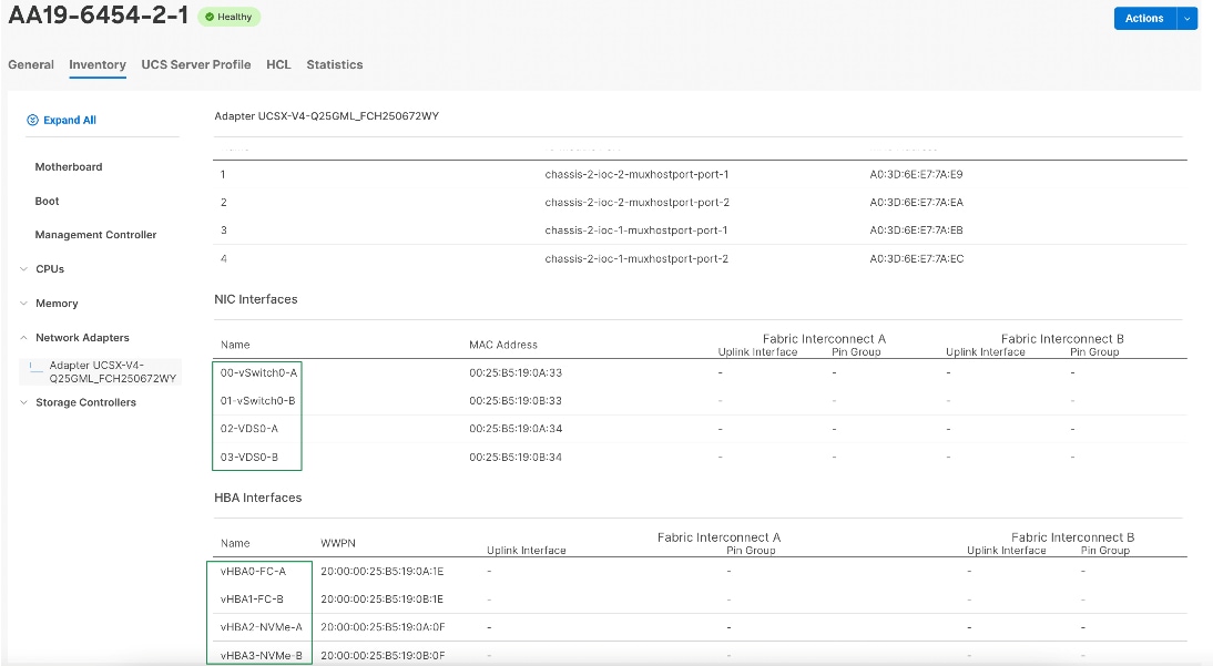
Boot Policy for SAN Boot
In this solution, the Cisco UCS X210c blade servers are configured to boot from the Pure Storage volumes. For the ESXi hosts to establish connections to the Pure Storage over Fibre Channel, required WWN names of the Pure Storage FlashArray need to be configured in the Boot policy. Gather the WWN names of scsi-fc ports of Pure storage array by executing “pureport list” command on the pure storage SSH terminal. Table 9 lists the information gathered from Pure Storage FlashArray for configuring the Boot Policy. Two target ports are used from each side of Fibre Channel switching fabric.
Table 9. WWN Names of Pure Storage FlashArray
| Controller |
Port Name |
Fabric |
Target Role |
WWN Name |
| FlashArray//XL170 Controller 0 |
CTO.FC4 |
Fabric A |
Primary |
52:4A:93:7D:FE:FB:53:04 |
| FlashArray//XL170 Controller 1 |
CT1.FC4 |
Fabric B |
Secondary |
52:4A:93:7D:FE:FB:53:14 |
| FlashArray//XL170 Controller 0 |
CTO.FC5 |
Fabric A |
Primary |
52:4A:93:7D:FE:FB:53:05 |
| FlashArray//XL170 Controller 1 |
CT1.FC5 |
Fabric B |
Secondary |
52:4A:93:7D:FE:FB:53:15 |
Once this information is gathered from the controller, a boot policy to boot from FC SAN is configured as shown below.
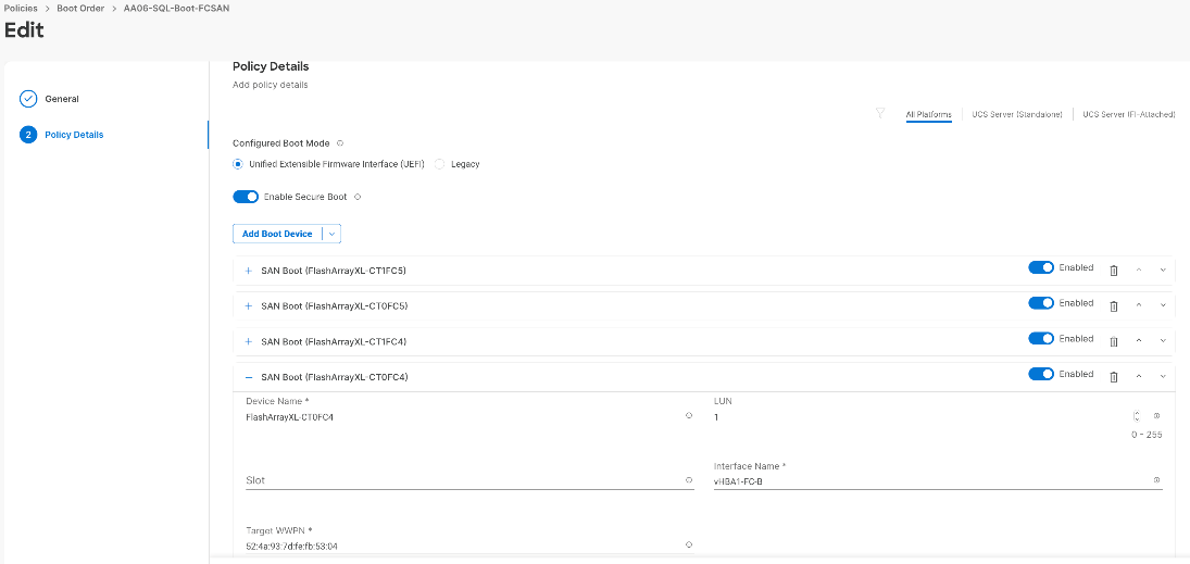
After the successful server profiles association by using the above boot policy and with right zoning configuration on the Cisco MDS switches is in place, the Cisco UCS X210c blade server should list four the paths to its boot volume while booting in to the ESXi.
BIOS Policy
It is recommended to use appropriate BIOS settings for the servers based on the workload they run. The default bios settings work towards power savings by reducing the operating speeds of processors and move the cores to the deeper sleeping states. These states need to be disabled for sustained high performance of database queries. For the server bios settings recommended for enterprise workloads are discussed in more detailed here: https://www.cisco.com/c/en/us/products/collateral/servers-unified-computing/ucs-b-series-blade-servers/performance-tuning-guide-ucs-m6-servers.html#AdditionalBIOSrecommendationsforenterpriseworkloads
Once the server profiles are created using the required policies and templates, they can be associated to the Cisco UCS X210c blades. When the server blades are powered on and the server must detect four paths to the target san boot volume if all the FC Switch zones are configured properly.
VMware vSphere ESXi Host Configuration
This section describes the VMWare ESXi host-specific configurations to be implemented on each ESXi host.
Update VIC Drivers
It is recommended to use latest VIC drivers for the specific vSphere ESXi hypervisor. For the most recent VIC driver versions, refer to: Cisco UCS Hardware & Software Interoperability Matrix. At the time of testing of this solution, the following are the versions of the VIC drivers that were used from the Cisco custom image for VMware vSphere 7.0.
Note: It is recommended to upgrade to the latest version that is available.
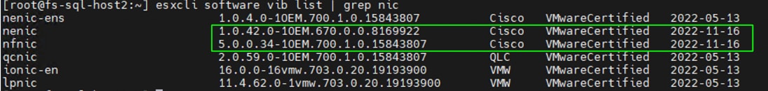
You can also validate and update from Cisco Intersight as shown below:
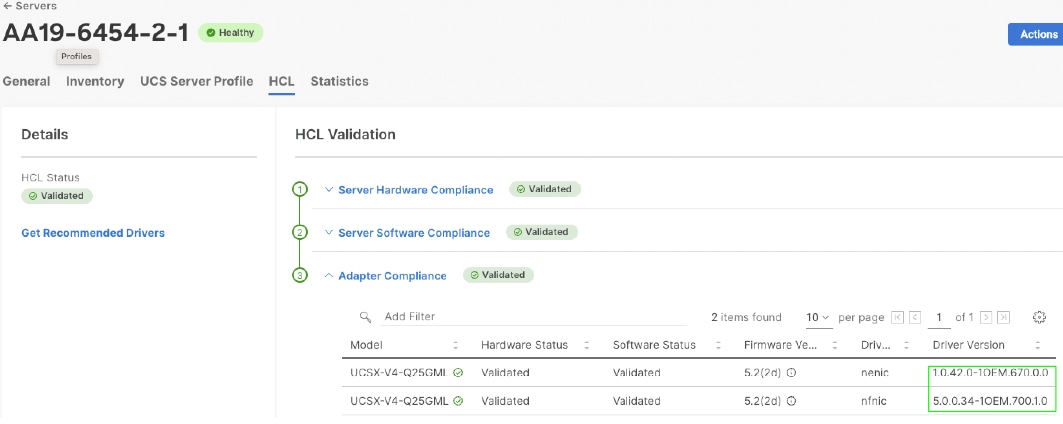
ESXi has been heavily tuned for driving high I/O throughput efficiently by utilizing fewer CPU cycles and conserving power. Hence the Power setting on the ESXi host is set to “Balanced.” However, for critical database deployments, it is recommended to set the power setting to “High Performance.” Selecting “High Performance” causes the physical cores to run at higher frequencies and thereby it will have positive impact on the database performance.
Verify Adapter IO Throttle Count and FC-NVMe Datastore Queue Depth
After creating and mounting a FC-NVMe based datastore in the vSphere cluster ( exposed using NQNs and fc-nvme adapters), ensure that “Device Max Queue Depth” for the datastore is set to 496. Also, ensure “nvme_io_throttle_count” for the adapter is set to 1024 as shown below. If it’s not set to 1024, it can be changed as shown below. Execute “esxcfg-scsidevs -m” to get the eui id of the datastores. For the other scsi-fc based boot LUNs, the default Device Max Queue Depth value set 32 which is acceptable for boot volumes.
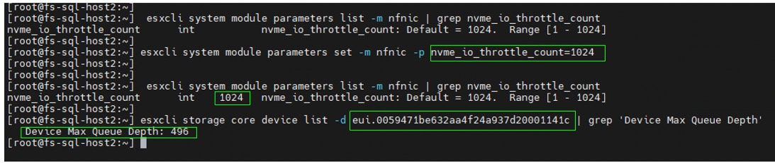
ESXi Host Networking Configuration
This section provides information about the ESXi host network configuration used for this FlashStack system. The ESXi host should discover four ethernet network adapters. The first two adapters are used for creating a standard switch (vSwitch0) which is used for management traffic while the last two adapters are used for creating Distributed Switch (vDS0) for the rest of the traffic. Table 10 lists the network configuration used for this solution.
Table 10. ESXi Host Network Configuration
| Configuration |
Details |
| Switch Name: vSwitch0 |
Purpose: For managing and accessing ESXi hosts ESXi Physical Adapters: vmnic0 (active) and vmnic1 (standby) VLAN: 1031 MTU: 1500 Port Groups Details: Management Network: For managing and accessing ESXi hosts. A VMkernel port (vmk0) is created and configured with management IP addresses on each ESXI host. |
| Switch Name: vDS0 |
Purpose: For Virtual Machine traffic (OCP Cluster traffic) and vMotion ESXi Physical Adapters: vmnic2 (Uplink 1) and vmnic3 (Uplink 2) VLANs: 1031 and 3319 MTU: 9000 Port Groups Details: VMNW_OCP-Mgmt (VLAN 1031): For managing and accessing OCP master and worker nodes. Uplink 1 and Uplink 2 are configured in active-active fashion vMotion (3319): For vMotion traffic. Uplink 2 is configured as active, and Uplink 2 is configured as Standby adapter. VMkernel port (vmk1) is created and configured with vMotion IP addresses on each ESXI host. |
Figure 31 shows ESXi network configuration used for this solution.
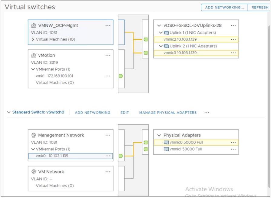
Preserve TPM Encryption Key
Typically hosts in FlashStack Datacenter are boot from SAN configured. Cisco UCS supports stateless compute where a server profile can be moved from one blade or compute node to another seamlessly. When a server profile is moved from one blade to another blade server with the following conditions, ESXi host runs into PSOD and ESXi will fail to boot.
● TPM present in the node (Cisco UCS M5 and Cisco UCS M6 family servers)
● Host installed with ESXi 7.0 U2 or above
● Boot mode is uEFI and Secure boot option is enabled
The error message “Unable to restore the system configuration. A security violation was detected: https://via.vmw.com/security-violation“ displays on the server console.
For more details about this known issue, go to: https://kb.vmware.com/s/article/81446
The cause for this error is that the server is not able decrypt the information as the TPM encryption key missing. The encryption key is stored on the servers ROM and did not get carry forward along with the service profile.
Until it is fixed in next Cisco UCS release, follow this workaround to boot new server successfully when you a service is migrated from one server to other:
1. After ESXi is installed, ssh in to the ESXi server. Execute the following command to list the recovery keys. Copy the Encryption key and store it in a safe location. Repeat this step for all ESXi servers.
esxcli system settings encryption recovery list
2. After the service profile is associated to a new server and while the ESXi server is booting, stop the ESXi boot sequence by pressing Shift+O.
3. At the boot command prompt, enter the recovery using following boot option: encryptionRecoveryKey=recovery_key
4. Enter to continue the boot process.
Note: Immediately after ESXi installation, ensure to take backup of the TPM encryptions key for each ESXi host and store them in a safe location.
Red Hat OpenShift Container Platform Deployment
This section explains Red Hat deployment steps at high level followed for this solution. For this VMware vSphere based FlashStack solution, the OCP is deployed using installer-provisioned infrastructure (IPI) method. A dedicated workstation is used for downloading OCP installation Program files and then installing OCP. From this workstation, all the OCP masters and workers are accessed and managed using SSH key pair.
Prior to beginning of the OCP deployment, the following prerequisite installation tasks need be to complete and gather the required information which is required for deploying OCP.
Prerequisites for Deploying OCP on vSphere
The primary requirement before proceeding with OCP deployment is to complete the deployment of FlashStack solution using VMware vSphere Hypervisor. Gather following information from the vSphere cluster.
● vSphere vCenter login credentials; To install an OpenShift Container Platform cluster in a vSphere cluster, the OCP installation program requires access to an account with privileges to read and create the required resources. Using an account that has global administrative privileges is the simplest way to access all the necessary permissions.
● OCP installation program requires access to the vCenter’s API for executing several steps. Hence vCenter server root CA certificate must be downloaded and added to the workstation’s system trust from which the OCP installation is kicked off. For the detailed steps to download and copy the vCenter certificate to the worker machine, please refer: https://docs.openshift.com/container-platform/4.10/installing/installing_vsphere/installing-vsphere-installer-provisioned-customizations.html#installation-adding-vcenter-root-certificates_installing-vsphere-installer-provisioned-customizations
● At least one FC-NVMe datastore which is mounted on all the ESXi hosts must be created to store OCP virtual machines in the cluster.
Networking Requirements
DHCP (Dynamic Host Configuration Protocol) must be used for the network IP assignment and DHCP server must be configured to provide persistent IP addresses to the OCP master and worker virtual machines. This ensures that the OCP virtual machines will get the same IP address after reboots. Once the OCP cluster is deployed, gather the MAC addresses of the OCP virtual machines and create the DHCP reservations as shown below:
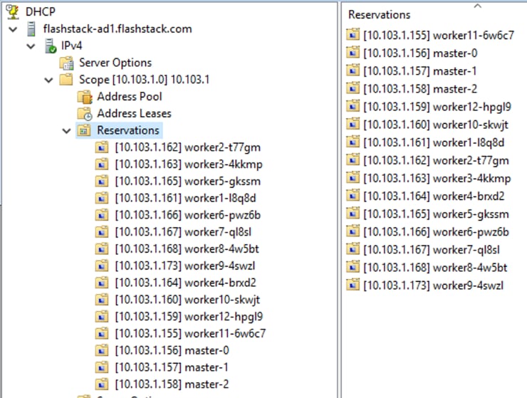
Required IP Addresses
An Installer-Provisioned vSphere Installation requires two static IP addresses. These addresses need to be provided to the OCP installation program during the OCP installation:
● Cluster API address: This IP address is used to access the OCP Cluster.
● Ingress address: This IP address is used for cluster Ingress traffic.
DNS Records
Using the above two static IP addresses, we must create two DNS records in a DNS server. In each record, <cluster_name> is the OCP cluster name and <base_domain> is the cluster base domain that you specify when you install the cluster. A complete DNS record takes the form: <component>.<cluster_name>.<base_domain>. For this installation, ‘flashstack.com’ is used as the base domain which is hosted in a machine which is outside of FlashStack vSphere cluster. A separate sub domain ‘sqlocp410’ is created for the OCP cluster and another sub domain ‘apps’ needs to be created under the OCP cluster sub domain (sqlocp410). Using the API Cluster IP address, a DNS records ‘api.sqlocp410.flashstack.com,’ is created. Similarly, using ingress IP address a wild card DNS record, ‘*.apps.sqlocp410.flashstack.com’ is created under ‘apps’ sub domain. The two DNS records are shown below:
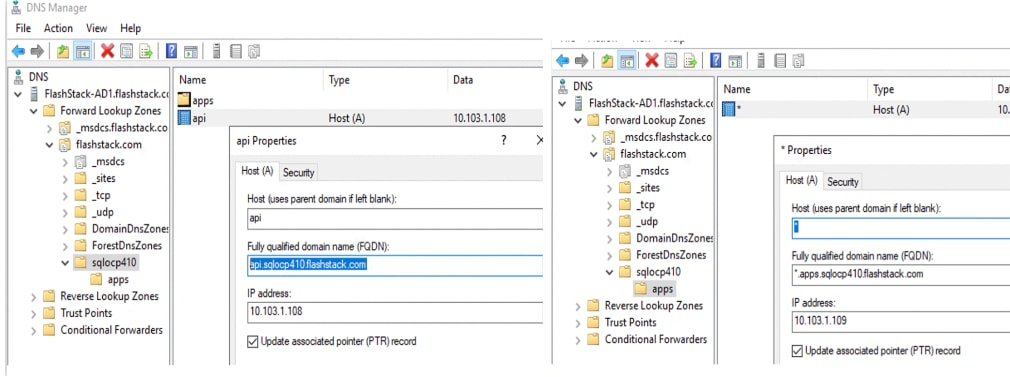
SSH Key Pair for OCP Cluster Node Access
To access and manage the OCP master and workers nodes from the workstation, we need to generate ssh key pair and pass it to the installation program during the OpenShift Container Platform installation. The key is passed to the Red Hat Enterprise Linux CoreOS (RHCOS) nodes through their Ignition config files and is used to authenticate SSH access to the nodes. The key is added to the ~/.ssh/authorized_keys list for the ‘core’ user on each node, which enables password-less authentication.
After the key is passed to the nodes, you can use the key pair to SSH in to the RHCOS nodes as the user ‘core.’ To access the nodes through SSH, the private key identity must be managed by SSH for your local user. For detailed steps to generate the ssh key pair and adding it to the ssh-agent, go to: https://docs.openshift.com/container-platform/4.10/installing/installing_vsphere/installing-vsphere-installer-provisioned-customizations.html#ssh-agent-using_installing-vsphere-installer-provisioned-customizations
Internet Access and Red Hat Account Requirements
The OCP installation using Installer-Provisioned Infrastructure (IPI) method normally requires Internet access to download Red Hat Enterprise Linux CoreOS (RHCOS) images and additional components which will be used to install the OCP cluster. The primary requirement before proceeding with OCP deployment is to complete the deployment of VMware vSphere.
A valid account is required to log in to the Red Hat OpenShift Cluster Manager page, to create the cluster and create the pull secret. The pull secret is created in the cluster manager webpage and downloaded, then the pull secret is supplied during the installation program. Afterwards, the cluster is listed in the Red Hat Hybrid Cloud Console, where its version and status can be viewed.
Download the Latest OCP Installation Program and OCP tools
Before installing OpenShift Container Platform, download the installation file to the worker machine that runs either Linux or macOS.
Procedure 1. Download the OCP Installation Program Files to the Worker Machine
Step 1. From the workstation machine, login to the https://console.redhat.com/openshift/install/ page with Red Hat account and click the Datacenter tab. Under the Datacenter tab, select vSphere for creating OCP cluster on vSphere-based cluster.
Step 2. Click Installer-Provisioned Infrastructure option.
Step 3. Click the Copy the Pull Secret button to copy it to the clipboard so it can be pasted into the OpenShift install program:
a. Select ‘Linux’ from the drop-down and click on “Download Installer” button to download the latest OCP Installation Program files.
b. Select ‘Linux’ from the drop-down and click on “Download Command-line tools” button to download the latest ‘oc’ and ‘kubectl’ tools
Step 4. To download the older OCP installation Program file and Command-line tools, use the following URLs. Update the OCP version numbers in the URLs before downloading the tools. For instance, the following URLs download the tools for OCP version 4.10.9:
Step 5. Extract the files and move ‘oc’ and ‘kubectl’ files to the /usr/local/bin/ folder.
Step 6. Verify ‘oc’ and ‘kubectl’ versions by executing ‘oc version’ and ‘kubectl version’
For the other prerequisites for the vSphere-based OCP deployment, go to: https://docs.openshift.com/container-platform/4.10/installing/installing_vsphere/installing-vsphere-installer-provisioned.html
The Red Hat OCP can be installed using the OCP Installation Program file which was downloaded and extracted as previously mentioned.
Procedure 1. Install Red Hat OCP
Step 1. From the workstation, change the directory where OCP Installation files are extracted. Create a directory with name matching with OCP Cluster name. For example, ‘sqlocp410’ directory.
Step 2. Run the command: ./openshift-install create cluster --dir=sqlocp410 --log-level=info
Step 3. Use the up/down arrow keys to select appropriate options and supply the correct values as shown in the below screen shot. The installation program should show the OCP cluster URL and the credentials after the successful OCP installation. Copy and store the password for the kubeadmin account as this is the only time it will be shown, and it is required to log in to the OpenShift management console webpage.
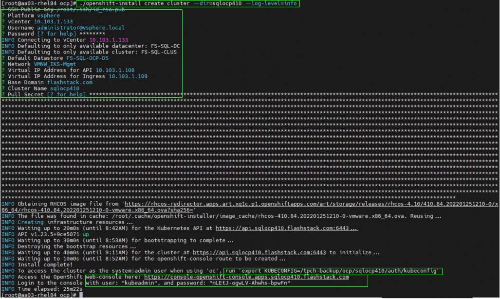
Step 4. When the OCP cluster is installed successfully, run the ‘export KUBECONFIG’ command and manage the OCP cluster using ‘oc’ command line tool to manage OCP cluster.
Step 5. When the OCP cluster is installed, the control node virtual machine may get scheduled on the same ESXi host. It is recommended to run the OCP control nodes on different ESXi host by creating anti-affinity rule in the vCenter as shown below.
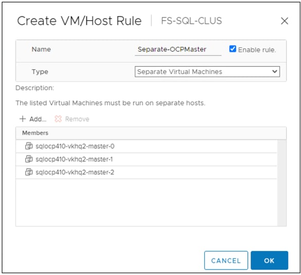
Scale OCP Cluster and Changing Resource Allocation for OCP Worker Nodes
By default, OCP deploys three master and three workers. The worker nodes can be scaled up or down using ‘machineset.’ Run the following commands to scale the workers from three to four without changing resource (CPU, Memory) allocated to the worker VMs:
oc get machinesets -n openshift-machine-api
oc scale machineset <machine set> --replicas=4 -n openshift-machine-api
These commands only scale the workers up or down, but it does not change the resources (CPU, Memory, and so on) allocated to the VMs. By default, worker node VMs are deployed with 2 CPU and 8GB RAM each. If this configuration is not sufficient for the workload pods you deploy, we can create a new machine-set with required resources and replicas. Otherwise, the default machineset can be with new resource values and apply the changes. The screenshot below shows the portion of the default machineset manifest file where the replicas are changed from 3 to 9, CPU are changed from 2 to 12 and memory is changed from 8 to 32GB.
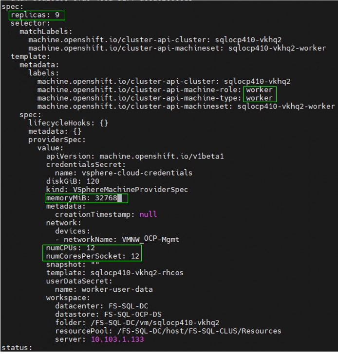
When the machineset is updated and applied with required resources, login to the vCenter and verify if the OCP worker virtual machines are reconfigured with resources specified in the machineset.
Optionally, a separate set of worker nodes can be created merely for hosting and running infrastructure components such as the default router, the integrated container image registry, and the components for cluster metrics and monitoring (Prometheus/Grafana and so on). This arrangement provides separation between the pods running your applications, from the services that run the OpenShift cluster itself. For this solution, there are no infrastructure machines are created.
In production environments, it is recommended to create additional infrastructure nodes to run several of the built-in cluster services, as opposed to running them on the worker nodes. For more details on infrastructure nodes, go to: https://docs.openshift.com/container-platform/4.10/machine_management/creating-infrastructure-machinesets.html
Portworx Enterprise Installation on OCP Cluster Running on vSphere Cluster
Portworx is fully integrated with Red Hat OCP. Hence you can install and manage Portworx from OCP web console itself. This section provides the steps for installing Portworx on OpenShift Container Platform running on vSphere cluster.
Prior to starting the Portworx installation, the following prerequisites need to be completed:
● The OCP Cluster (version 4.0 or higher) should be deployed on a vSphere cluster.
● You should be able to access the OCP web console using the ‘kubeadmin’ login
● Ensure ports 17001-17020 on worker nodes are reachable from the control plane node and other worker nodes.
● One FC-NVMe based datastore to be created and mounted on the ESXi hosts. This datastore is used for storing VMDK files for Portworx uses for creating distributed storage cluster.
● vCenter credentials with privileges to read and update the virtual machine configuration. The vCenter credentials need to be created as a Secret object in the OCP Kubernetes cluster. Create the Secret object using vCenter credentials as follows:
echo 'administrator@vsphere.local' | base64
YWRtaW5pc3RyYXRvckB2c3BoZXJlLmxvY2FsCg==
echo 'YWRtaW5pc3RyYXRvckB2c3BoZXJlLmxvY2FsCg==' | base64 --decode
administrator@vsphere.local
echo <'your Password'> | base64
SCFnaFYwbHQK
echo 'SCFnaFYwbHQK' | base64 --decode
## Create secret for vCenter user:
cat px-vsphere-secret.yml
apiVersion: v1
kind: Secret
metadata:
name: px-vsphere-secret
namespace: portworx. ## enter the Project/namespace name created for Portworx deployment.
type: Opaque
data:
VSPHERE_USER: YWRtaW5pc3RyYXRvckB2c3BoZXJlLmxvY2FsCg==
VSPHERE_PASSWORD: SCFnaFYwbHQK
Create the px-vsphere-secret.yml spec file in the project in which the Portworx is created as shown below:
oc apply -f px-vsphere-secret.yml -n portworx
Procedure 2. Deploy Portworx on OCP running on vSphere
Step 1. Install the Portworx Operator using Red Hat OperatorHub.
Step 2. Deploy Portworx using the Operator.
Step 3. Verify the Portworx installation.
Install Portworx Operator from OCP OperatorHub
Procedure 1. Install Portworx from the OCP OperatorHub
Step 1. Login with OCP web console using kubeadmin user. On the Operators tab, click on ‘OperatorHub’ and select Portworx Enterprise Operator.
Step 2. Click Install to install Portworx Enterprise Operator.
Step 3. The Portworx Operator begins to install and takes you to the Install Operator page. On this page, select a ‘specific namespace on the cluster’ option for Installation mode. Select an existing Project name or select ‘Create Project’ option from the Installed Namespace drop-down list.
Step 4. If ‘create project’ is selected, enter the project name ‘portworx’ and click Create to create a dedicated namespace for Portworx.
Step 5. Click Install to deploy the Portworx Operator in the required namespace that was selected in the previous steps.
Deploy Portworx using the Operator
The Portworx Enterprise Operator takes a custom Kubernetes resource called ‘StorageCluster’ as input. The StorageCluster is a representation of your Portworx cluster configuration. Once the StorageCluster object is created, the Operator will deploy a Portworx cluster corresponding to the specification in the StorageCluster object. The Operator will watch for changes on the StorageCluster and update your cluster according to the latest specifications. The StorageCluster specification for the OpenShift Cluster running on vSphere can be generated using the site: https://central.portworx.com/landing/login
Procedure 2. Generate the StorageCluster Specification for the OCP Cluster
Step 1. Login with your portworx credentials and select Portworx Enterprise on the Product Catalog page.
Step 2. On the Product Line page, select Portworx Enterprise and click Continue.
Step 3. Select Basic option and click the Use the Portworx Operator checkbox. Select the latest Portworx version (2.12 at the time of writing this document) enter the Kubernetes version, then enter the namespace as ‘portworx.’ Select the Built-in option for Portworx integrated Key Value Database (KVDB). Click Next.
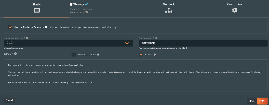
Step 4. From the Storage tab, select Cloud for the Environment and select vSphere from drop-down list. For the KVDB device type, leave it at the default setting as ‘Lazy Zero Thick Provisioning’ and enter 32G for Size. For the volume type leave the default setting as ‘Lazy Zero thick Provisioning Disk’ and enter 512G for Size. Click the ‘+’ symbol to add additional volumes (vmdks) for additional capacity to the Portworx cluster.
Step 5. For the Max storage nodes per availability zones, enter the appropriate number of PX nodes that contribute storage to the Portworx StorageCluster.
Step 6. Enter the vCenter IP address for the vCenter Endpoint and leave the default vCenter port 443. Enter the ESXi datastore (FC-NVMe based) name for vCenter datastore prefix and enter the vSphere secret name that was created in the previous steps.
Step 7. Click Next.
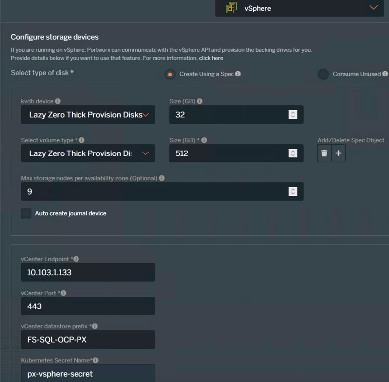
Step 8. From the Network tab, leave the Data and management Network Interface as Auto. Click Advanced Settings, leave the Starting port for PX service as 9001. Click Next.
Step 9. From the Customize tab, select OpenShift 4+ for the cluster environment. If you are using Proxy, the Proxy details can be provided under the Environmental Variables.
Step 10. Click Advanced Settings. Select Enable Stock, Enable CSI, and Enable Monitoring options. Enter a name for the Portworx cluster and click Finish.
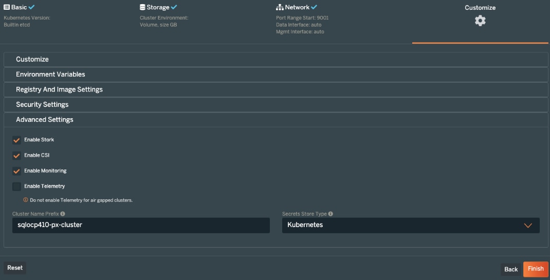
Step 11. On the final page, enter a name for the StorageCluster specification file and tags. Click Download. Optionally, the specification can be saved by clicking the Save Spec button.
Step 12. When you have the StorageCluster specification, it can be applied using CLI or OpenShift UI. For applying using CLI, enter the following commands:
oc apply -f <StorageCluster-Specification.yml>
Step 13. To create StorageCluster using OpenShift UI, login to the OpenShift web console click Installed Operators. Click Portworx Enterprise operator and then click the Storage Cluster option.
Step 14. From the StorageCluster tab, click Create StorageCluster.
Step 15. From the Create StorageCluster window, select YAML view. Copy and paste the content of the specification file downloaded in the previous step. Click Create.
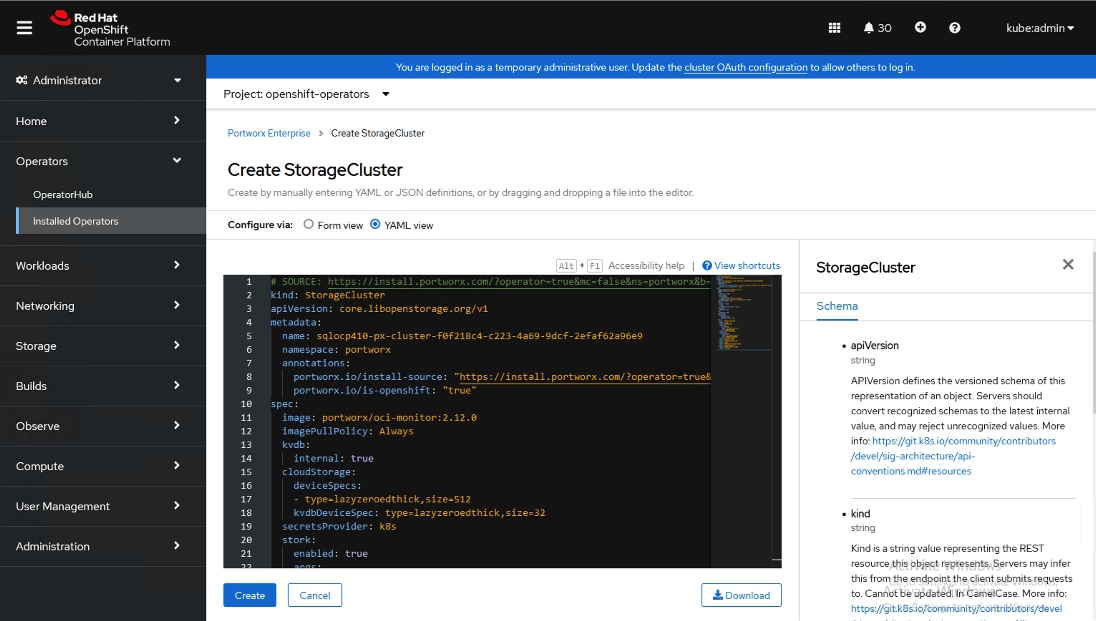
When the Portworx is fully deployed the status displays as Online.
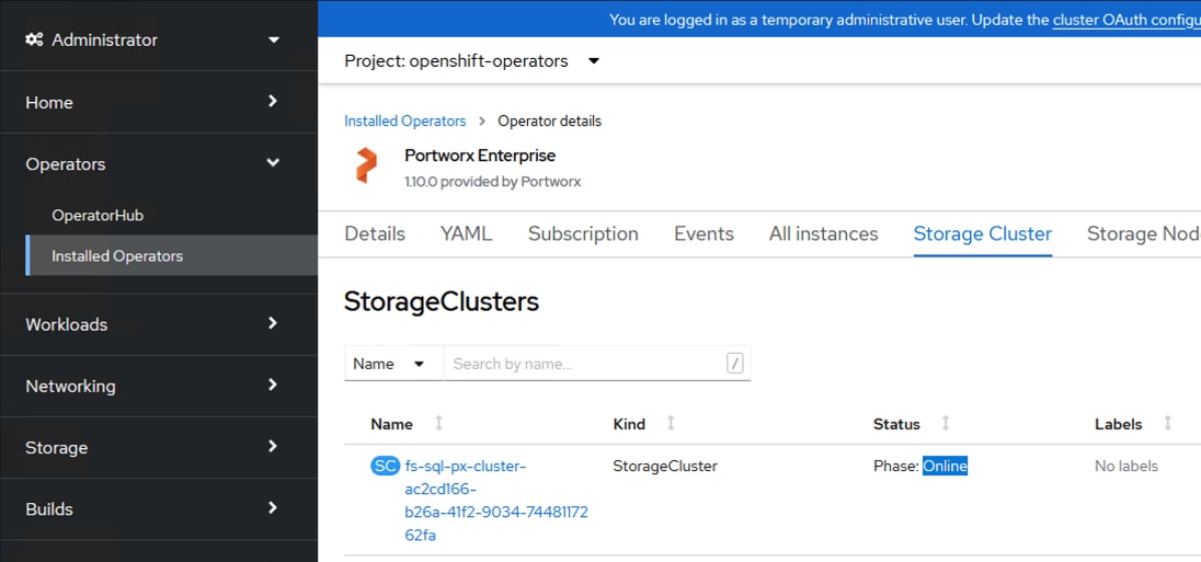
Procedure 3. Verify the Portworx Installation
Step 1. When the StorageCluster comes online, the following commands can be run for verifying if the Portworx installed correctly:
watch oc get pods -o wide -n <namespace>
The following figure shows the status of all the Portworx related pods when there are nine worker nodes in the OCP cluster.
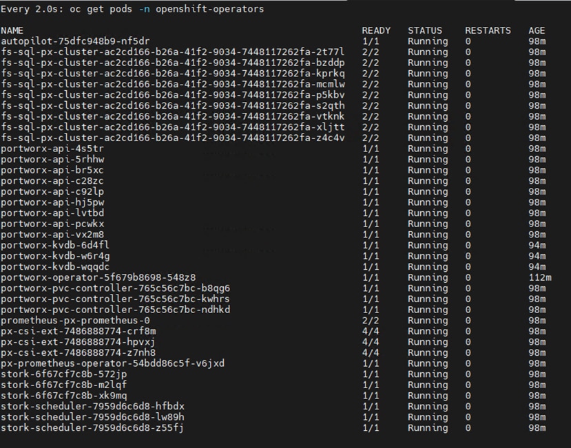
The following figure shows the Portworx cluster status, their nodes, and capacity of cluster for the same nine node OCP cluster. As shown below, the Portworx is operational, running on all the nine worker nodes and 4.5TB is the total capacity of the Portworx cluster.
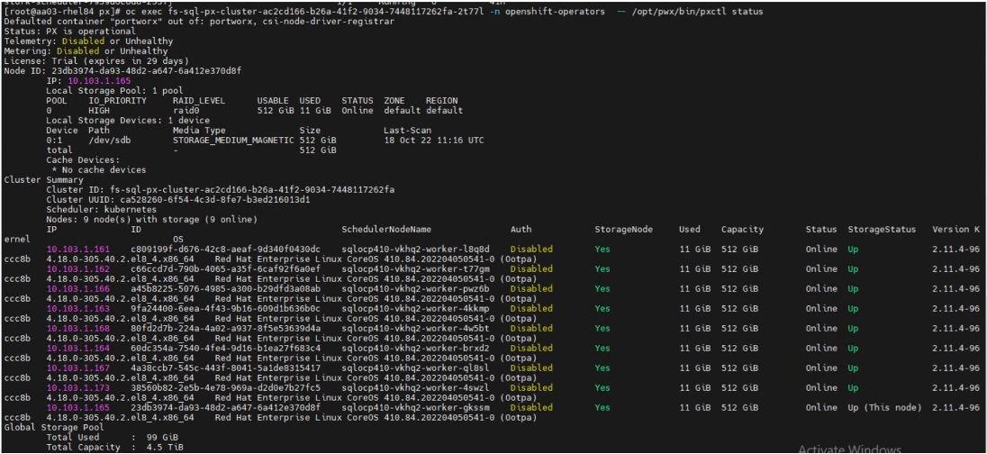
Scaling Portworx
Portworx is deployed as a Daemonset. Therefore, it automatically scales as you grow your OCP Kubernetes cluster. There are no additional requirements to install Portworx on the new nodes in your Kubernetes cluster. For instance, when the OCP workers are scaled from nine to twelve using OCP machineset command, the Portworx is also scaled accordingly as shown in the following figure. Notice that the total capacity is increased from 4.5TiB to 6TiB and that the “maxStorageNodesPerZone” parameter needs to be changed and applied if you want the new nodes to contribute to the storage cluster capacity.
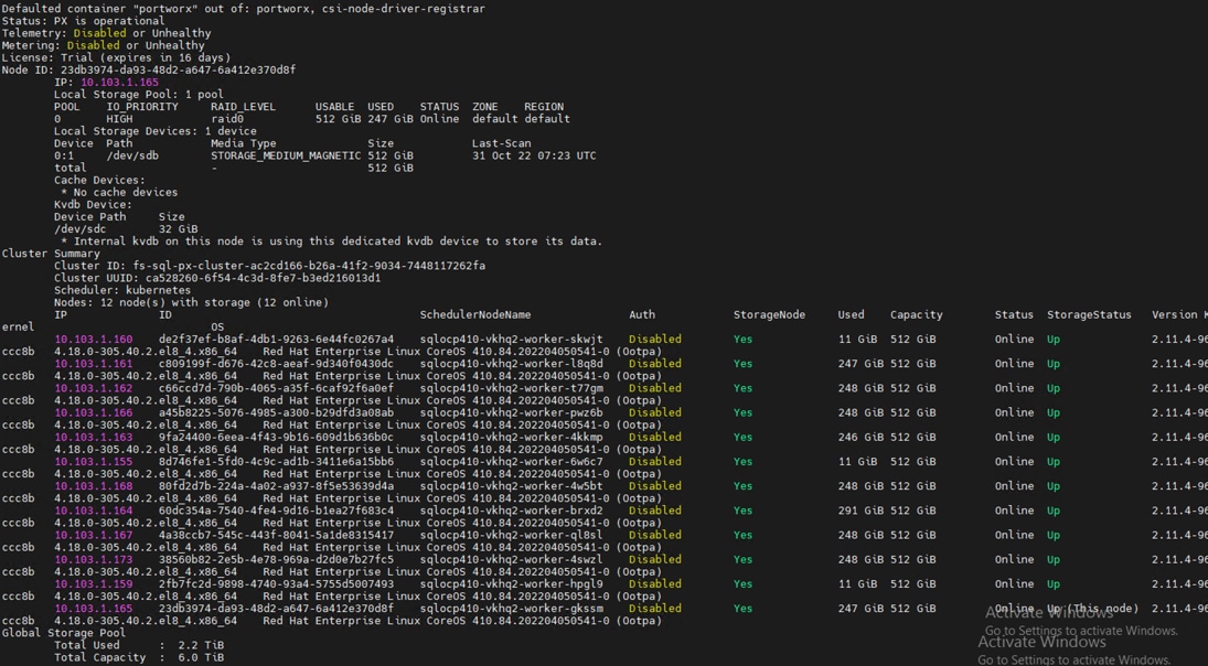
Restrict Portworx to Specific Worker Nodes
To restrict Portworx to run on only a subset of nodes in the OCP Kubernetes cluster, you can use the ‘px/enabled’ label on the minion nodes you do not wish to install/run Portworx on. Run the following command to prevent Portworx from installing and starting on specific OCP worker nodes.
oc label nodes <ocp worker names> px/enabled=false –overwrite
Portworx Volume Placement Strategy
When you provision volumes, Portworx places them throughout the cluster and across configured failure domains to provide fault tolerance. While this default manner of operation works well in many scenarios, you may wish to control how Portworx handles volume and replica provisioning more explicitly. You can do this by creating VolumePlacementStrategy CRDs. Within a VolumePlacementStrategy CRD, you can specify a series of rules which control volume and volume replica provisioning on nodes and pools in the cluster based on the labels they have.
● ReplicaAffinity and ReplicaAntiAffinty Rules: these rules allow us to place the volume replicas on certain specific failure domains. These rules help us to achieve better availability of the volume protecting.
● VolumeAffinity and VolumeAntiAffinity Rules: these rules allow us to co-locate the volumes and volume replicas of a pod on a same worker node there by avoiding remote access which results in better IO latencies.
For instance, two volumes are used in a traditional SQL Server databases deployment. The first volume (Data volume) is used for storing database data files while the second volume (Log volume) is used for storing Transaction Log files. It is recommended to ensure that these two volumes and their corresponding replicas are always co-located on a same node instead of having Data and LOG volumes provisioned from two different nodes. Which helps the Portworx scheduler (stork) to schedule the SQL pod on a worker node where Data and Log volumes are located.
The following figure provides a Volume Placement Strategy specification. It simply co-locates the two volumes pod1-data1-pvc and pod1-log1-pvc that have label “app: mssql-pod1” on a same worker node. When a pod is created using these two volumes, the Stork scheduler will schedule the pod on the worker node which has these two volumes co-located.
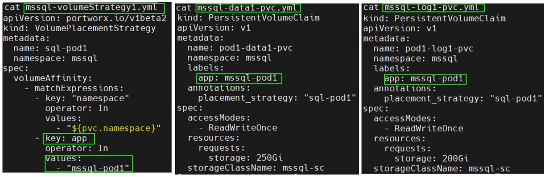
For the detailed information on the Volume Placement polices, go to: https://docs.portworx.com/operations/operate-kubernetes/storage-operations/create-pvcs/volume-placement-strategies/
Portworx IO Profiles
You can optimize the performance of your Portworx volumes by matching the type of workload you’re running with a suitable IO profile. IO profiles change the how a Portworx volume interacts with the underlying storage disks to improve traffic for different workloads. For this validation, ‘db_remote” IO profile is used for database deployments. Refer this page for detailed explanation of various IO profiles: https://docs.portworx.com/concepts/io-profiles/
IO Priority
For IO sensitive database workload, it is recommended to use to io_priority option to “high.” SQL Server database pod volumes are created with io_prority set to high. Other accepted values for io_priority is low or medium with ‘low’ being the default value.
Replication Factor
Portworx allows us to specify whether the volumes to be highly available and protected from worker node failures. For instance, if a volume is created with a replication factor of 3, it means that data is protected on 3 separate nodes. For applications that require node level availability and read parallelism across nodes, it is recommended to use replication factor of 2 or 3. Note that the maximum replication factor is 3 while 1 being the default value.
For critical production database deployments, replication factor 3 can be used while for development and test database deployments, replication factor of 1 can be used.
Storage Class for Database Deployments
Optionally, a dedicated storage class can be used for various environments with required PX level settings as explained above. While requesting the Portworx volumes, required storage class can be used in the PVCs. For instance, the following screen shot shows a storage class with all the optimal settings for production database deployments.
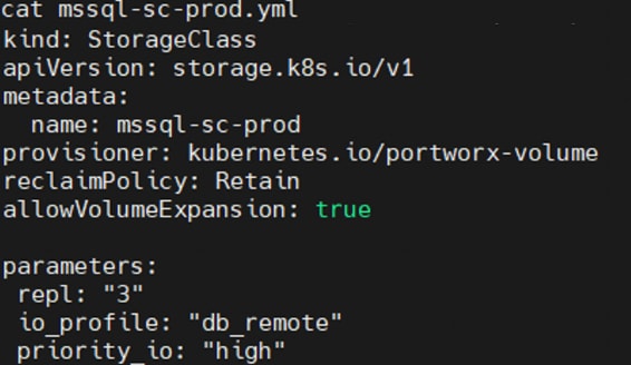
Portworx Runtime Options for Performance Optimization
In its default configuration, Portworx attempts to provide good performance across a wide range of situations. However, you can improve your storage performance on Kubernetes by configuring several settings and leveraging features Portworx offers. This section provides some of the runtime options that can be enabled for improved IO latencies and performance.
By default, Portworx consumes as little CPU and memory resources as possible. You can potentially improve performance by allocating more resources, allowing Portworx to use more CPU threads and memory. For IO latency sensitive applications like databases, it is recommended to ensure the Portworx pods and the application pods (in this context, SQL databases pods), running in the same worker node, get their own share of CPU threads (meaning dedicated CPU threads). This is achieved using runtime options for Portworx pods.
For detailed information on these options, go to: https://docs.portworx.com/operations/operate-kubernetes/tune-performance/
Deploy Microsoft SQL Server Database Pods using Portworx Volumes
The container image hosting SQL Server instance can be deployed as a Deployment object with Single ReplicaSet in Kubernetes. When the SQL Server pod or the worker node hosting the SQL Server pod goes down, the pod can be automatically rescheduled on the same or different worker node. As the SQL Server database is a stateful application, persistent storage volumes should be used for storing database data and transaction log files persistently across the reboots. When the pod comes online on a node, the same persistent volumes will be reattached to the pod there by maintaining the data persistency across the pod restarts.
The Deployment manifest for deploying a SQL Server pod using Portworx Persistent volumes is given below. The important things that need attention are as follows:
● Portworx Scheduler: When using the Portworx storage volumes, it is recommended to use the “stork” scheduler as the stork scheduler will have a complete picture of the volumes, volume replica’s location. Hence it can make better decisions and intelligently schedule the SQL Server pods on the right worker nodes based on data location.
● Resource Limits: When you have multiple pods running within a worker node, the Kubernetes resource limits can be used to restrict CPU and memory utilization of each pod. It assists to segregate the resources dedicated to the pods and avoids unwanted resource congestion issues within the OCP worker node. In the following example, resource limits are used to restrict the pod to use up to 4 CPUs and 12Gi memory when it’s deployed on a worker node configured with 12 CPUs and 36GB memory.
● SQL Server Service Type: the snippet (below) exposes SQL Server pod using service type ‘NodePort’ on port number 30001 for external connectivity. SQL Server Management studio can be used to manage the instance using < WorkerNode-IPAddress,PortNumber>. Optionally, service type “ClusterIP” can be used for accessing the database pod with in the OCP cluster. By using the LoadBalancer service type, the SQL Server instance can be made accessible remotely (via the Internet) at a specific port. However, from a security perspective, it is not a good practice to expose the SQL Server database engine to the internet.
● Separation of Data and T-Log files: Two separate Portworx volumes are used for storing the data and T-Log files of user databases. Additional volumes can be provisioned for storing data files, Tempdb files, backups, and so on.
● SQL Server container image version: The below manifest pull and deploy SQL Server 2019 image. One can simply move to a newer SQL Server image (2022) by simply changing the version from “2019” to “2022”.
● SQL Server SA password: As a prerequisite, before deploying the SQL Server pod, a secret object must be created consisting of password for ‘SA’ user. Use the following command to create a password for the SA user.
kubectl create secret generic mssql --from-literal=SA_PASSWORD="<your SA Password>"
● Security Context: Defines the privilege and access control settings for the pod. It is recommended to run the SQL Server pod with a non-root user. fsGroup 10001, the Group ID (GID) of ‘mssql’ service account, is used to run the SQL Server pod. When deploying the SQL Server in an OCP environment with a non-root user, it is required to create a Security Context Constraint (SCC) at the OCP level and add it to the MSSQL service account. Refer to the Appendix for the SCC manifest file to create the SCC and for the command to add the SCC to the MSSQL account.
The manifest for deploying a SQL Server pod on OCP cluster using Portworx volumes:
apiVersion: apps/v1
kind: Deployment
metadata:
name: mssql-dep1-pod
namespace: mssql
spec:
replicas: 1
selector:
matchLabels:
app: mssql
template:
metadata:
labels:
app: mssql
spec:
schedulerName: stork
terminationGracePeriodSeconds: 30
securityContext:
fsGroup: 10001
hostname: mssql-pod1
containers:
- name: mssql
image: mcr.microsoft.com/mssql/server:2019-latest
ports:
- containerPort: 1433
resources:
limits:
cpu: 4000m
memory: 12Gi
env:
- name: MSSQL_PID
value: "Developer"
- name: ACCEPT_EULA
value: "Y"
- name: SA_PASSWORD
valueFrom:
secretKeyRef:
name: mssql
key: SA_PASSWORD
volumeMounts:
- name: mssql-data
mountPath: /var/opt/mssql
- name: mssql-log
mountPath: /mnt/mssqllogs
- name: mssqlconf
mountPath: /var/opt/mssql/mssql.conf
subPath: mssql.conf
volumes:
- name: mssql-data
persistentVolumeClaim:
claimName: pod1-data1-pvc
- name: mssql-log
persistentVolumeClaim:
claimName: pod1-log1-pvc
- name: mssqlconf
configMap:
name: mssqlconf
---
apiVersion: v1
kind: Service
metadata:
name: mssql-pod1-svc
namespace: mssql
spec:
selector:
app: mssql
ports:
- protocol: TCP
port: 1433
nodePort: 30001
type: NodePort
Additional SQL Server Configuration
Microsoft has provided a configuration script called "mssql-conf" for the Linux based SQL Server to make the SQL Server database engine configuration changes. This utility is useful to set parameters, such as the default data file location, default log file location, TCP ports, limiting the maximum available physical memory to the pod, and so on. It can also be used to specify the start-up parameters such as trace flags. Using the mssql-conf tool, the required configuration and startup parameters of the SQL Server instance can be configured and stored in a mssql.conf file. These configuration and startup parameters will vary from deployment to deployment. It is recommended to test them before using in the production deployment. The following figure shows a sample mssql.conf file with a few configuration and startup parameters. When all required startup parameters are added to the mssql.conf file, it can be injected into the pod as a Kubernetes ConfigMap object. This ConfigMap (mssql.conf) can be passed to the SQL Server pod as a volume mount point as shown in the provided script (above). With this method, the SQL Server engine configuration is decoupled from the pod definition manifest, and it provides you with the ability to use a standard configuration across pods in your cluster. For more details on the mssql-conf utility, go to: https://learn.microsoft.com/en-us/sql/linux/sql-server-linux-configure-mssql-conf?view=sql-server-ver16.
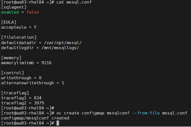
In addition to the CLI and GUI configurations explained in this deployment guide, all FlashStack components support configurations through automation using Ansible. The FlashStack solution validation team will share automation modules to configure Cisco Nexus, Cisco UCS, Cisco MDS, Pure Storage FlashArray, VMware ESXi, and VMware vCenter. This community-supported GitHub repository is meant to expedite customer adoption of automation by providing them sample configuration playbooks that can be easily developed or integrated into existing customer automation frameworks.
A repository is created in GitHub with Ansible playbooks to configure all the components of FlashStack including:
● Cisco UCS in Intersight Managed Mode
● Cisco Nexus Switches
● Cisco MDS Switches
● Pure FlashArray
● VMware ESXi
● VMware vCenter
The GitHub repository of Ansible playbook is available here: https://github.com/ucs-compute-solutions/FlashStack_IMM_Ansible
The components in this solution, such as Red Hat OCP, regular automated installer options, are described in the Red Hat OpenShift Container Platform Deployment section.
To deploy Microsoft SQL Server pod on a OCP cluster, go to https://github.com/ucs-compute-solutions/MSSQL-Deployment/ for instructions and the Ansible Playbook repository.
Validation
This chapter contains the following:
● Performance Tests and Results
The FlashStack system is tested and validated with Microsoft SQL Server databases for OLTP (Online Transaction Processing) workloads. Microsoft SQL Server databases are deployed as pods in the OCP cluster which in turn deployed on a highly available vSphere cluster connected to back end Pure Storage FlashArray//XL170 using high performing FC-NVMe protocol.
The Portworx storage cluster provides the required persistent storage volumes to the SQL pods. Each SQL pod runs one x 100G OLTP database stored on two storage volumes attached to the pod. One 250G volume provisioned to store data files and one 200G volume is provisioned to store the transaction log file of the test database.
HammerDB is an opensource test tool typically used for simulating OLTP or DSS like workloads on various types of relational databases. For this testing, HammerDB tool is installed in a separate machine which is outside of the FlashStack testbed. One instances of the HammerDB is used to generate OLTP-like workload on one SQL Server database pod running inside a dedicated OCP worker node. Therefore, for this testing multiple HammerDB instances (for example eight HammerDB instances) were used to test multiple SQL Server database pods (Eight database pods). At the end of each test, the each HammerDB instance tool reports Transactions Per Minute (TPM) metric for the specific of SQL Server database the test was executed on.
The performance tests are designed to demonstrate the two following aspects of the FlashStack system:
● Demonstrate database performance scalability within a single ESXi host by deploying multiple database pods.
● Demonstrate database performance scalability across a 3-Node vSphere cluster by deploying multiple database pods.
In these tests, SQL Server database pods are limited to use 9GB memory only (for a 100G database) to avoid caching or buffering with SQL Server and thereby driving more IOPS on the storage. Also, by tuning HammerDB script and SQL Server configuration, a read-write ratio of nearly 70:30 is maintained to represent most common database deployments.
Database deployments are typically CPU and IO intensive. Hence it is not recommended to run database workloads along with other applications within a worker node or a virtual machine to avoid noisy neighbor problems. It’s also beneficial to find out the root cause quickly when troubleshooting the performance related issues. In this testing, one SQL server database pod is deployed per worker node.
The following tuning options are used for the following performance tests:
● The database volumes are created with using following options:
◦ io_profile: db_remote
◦ io_priority: high
◦ repl: 1. For this specific testing, the Portworx volumes are provisioned with repl=1. For applications that require node-level availability and read parallelism across nodes, Pure Storage recommends setting a replication factor of 2 or 3. Note that the maximum replication factor is 3. Please refer to the Portworx documentation here: https://docs.portworx.com/reference/cli/create-and-manage-volumes/inspect-volumes/.
● Used volume placement strategy policies to co-locate the Data and T-Log volumes on the same worker node.
● Portworx runtime options: For this performance test, 8 threads are used for both IO and CPU work of Portworx on a worker node configured with 12 CPUs.
● One SQL pod per worker node.
● Additional Operating System level tunings were used, as suggested by Microsoft here: https://learn.microsoft.com/en-us/sql/linux/sql-server-linux-performance-best-practices?view=sql-server-ver16. For specific details, refer to the Appendix.
Database Performance Scalability within a Single Cisco UCS X210c M6 ESXi Host
The objective of this test is to demonstrate how database performance scales as SQL Server database pods are scaled-up from one to up to eight within a single Cisco UCS X210c M6 ESXi host.
Table 11 lists the OCP worker configuration and SQL Server pod configuration used for this testing.
Table 11. OCP worker and SQL Server Database Pod Configuration used for a Single Cisco UCS X210c Scalability Test
| Component |
Details |
| OCP Cluster |
3x Masters (each master is configured with 4x vCPUs and 16GB Memory) 8 Worker nodes (each worker node is configured with 12x vCPUs and 32GB Memory) |
| SQL Server Database pod (Limits and Resources) |
4 vCPUs and 12GB Memory max degree of parallelism: 4 max server memory(MB): 9216 |
| Storage Volumes |
Onex 250G volume for data files and TempDB data files Onex 200G volume for Transaction Log files and TempDB log files |
| Testing Tool |
HammerDB, 5 Users per SQL Server pod |
| Workload Details Per pod |
Database Size: 100G (8x Data files and 1x LOG file) Metrics Capture: Transactions Per Minutes (TPM) using HammerDB
|
| Monitoring Tools |
Prometheus and Grafana Dashboards for capturing Worker and pods level metrics like CPU, Memory, Storage IOPS and so on. ESXTOP ESXi CPU utilization |
Figure 48 describes performance (TPM) scalability within a single Cisco UCS X210c host. Transaction Per Minute (TPM) scaled well as the SQL Server database pods are scaled up from one to eight within a single ESXi host. As shown, a single SQL Server database pod delivered about 120,00 TPM utilizing nearly 7.5% CPU on the ESXi host. As the database pods are scaled from one to eight, the TPM scaled well. The CPU utilization has also scaled well from 7.5% to nearly 50% as pods are scaled from one to eight.
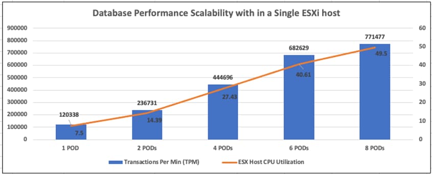
Figure 49 shows the corresponding disk data transfers (IOPS) and latency details for the test described above. These metrics are directly collected from the SQL Server database pods. As shown, a single database pod delivered around 13,000 IOPS (read and write IOPS combined in 70:30 ratio) and the IOPS scaled up to nearly 84,000 as the pods scaled from one to eight. The latencies stayed under 0.5ms.
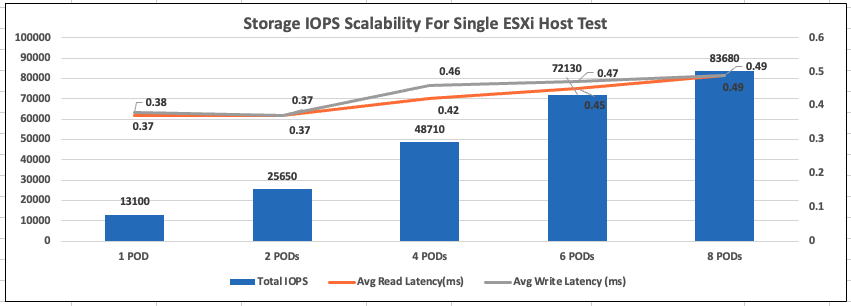
Database Performance Scalability across vSphere Cluster
The objective of this test is to demonstrate how the database performance scales when SQL Server database pods are scaled up across a three-host ESXi cluster.
As discussed above, one SQL Server database pod is deployed on one OCP worker node and one OCP worker node per ESXi host. The test started off with three pods, one on each ESXi host. The pods are scaled up to twelve pods by adding more worker nodes to each ESXi host. Twelve HammerDB instances are created on a client machine each stressing each database pod. The same OCP worker node configuration and database pod configuration that is used for Single ESXi host testing is retained for this ESXi cluster testing as well.
As shown in Figure 50, three SQL Server pods, deployed across the three-node ESXi cluster (using three OCP workers), delivered around 350,000 TPM with an average ESXi host CPU utilization of 7.5%. As the database pods are scaled (up to twelve) in the multiples of three, the TPM is scaled near linearly. The CPU utilization of the cluster also scaled near-linearly from 7.5% to 27.54% as shown below.
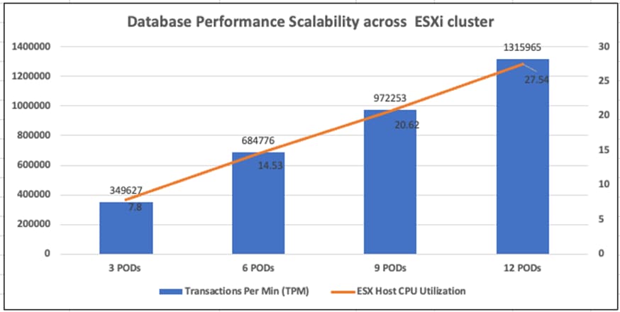
Figure 51 shows the corresponding disk data transfers (IOPS) and latency details for the test described above. These metrics are directly collected from the SQL Server database pods. As shown, three pods delivered about 38,000 disk operations. As the pods scaled from three to twelve, the IOPS scaled from 38,000 to 150,000. The latencies stayed well under 0.5ms.
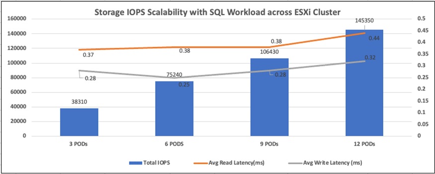
These performance tests showed as more database pods are added to the FlashStack system, the database performance and storage IOPS are scaled well and maintained the IO latencies under 0.5ms. This scalability is achieved with FlashStack system as all the components are optimized for delivering high performance for resource intensive critical database workloads.
FlashStack is the optimal shared infrastructure foundation to deploy a variety of IT workloads. The solution discussed in this document is built on the latest hardware and software components to take maximum advantage of both Cisco UCS compute and Pure Storage for deploying performance sensitive workloads such as Microsoft SQL Server databases.
In addition to the traditional enterprise grade offerings such as snapshots, clones, backups, Quality of Service, by adapting NVMe-oF technologies, this solution extends both Flash and NVMe performance to the multiple ESXi servers over the traditional Fibre Channel fabrics. This CVD provides a detailed guide for deploying Microsoft SQL Server 2019 database containers on Red Hat OpenShift Container Platform running on vSphere cluster. Portworx provides highly performing, resilient and persistent storage volumes for the SQL Server database pods. The performance tests detailed in this document validates the FlashStack solution delivering a consistent high throughput at sub millisecond latency required for high performance, mission critical databases.
This solution, which combines traditional FlashStack System with Red Hat OCP backed by Portworx Enterprise storage platform, provides a pre-validated, high performing, agile and scalable system that enables customer to achieve modern application development practices for deploying any type of workloads including CPU and IO sensitive applications such as Microsoft SQL Server databases.
Gopu Narasimha Reddy, Technical Marketing Engineer, Cisco Systems, Inc.
Gopu Narasimha Reddy is a Technical Marketing Engineer in the Cisco UCS Datacenter Solutions group. Currently, he is focusing on developing, testing, and validating solutions on the Cisco UCS platform for Microsoft SQL Server databases on Microsoft Windows, VMware, and Kubernetes platforms. He is also involved in publishing TPC-H database benchmarks on Cisco UCS servers. His areas of interest include building and validating reference architectures, development of sizing tools in addition to assisting customers in SQL deployments.
Acknowledgements
For their support and contribution to the design, validation, and creation of this Cisco Validated Design, the authors would like to thank:
● Vadi Bhat, Principal Engineer, Cisco Systems, Inc.
● Babu Mahadevan, Technical Leader, Cisco Systems, Inc.
● John McAbel, Product Manager, Cisco Systems, Inc.
● Chris Kennedy, Cloud Solutions Architect, Pure Storage, Inc.
● Anthony Nocentino, Field Solutions Architect, Pure Storage, Inc.
● Joe Houghes, Senior Solutions Architect, Pure Storage, Inc.
● Craig Waters, Technical Director, Pure Storage, Inc.
GitHub repository for solution deployment: https://github.com/ucs-compute-solutions/FlashStack_IMM_Ansible
GitHub repository for deploying Microsoft SQL Server pod on OCP cluster: https://github.com/ucs-compute-solutions/MSSQL-Deployment/
Cisco Intersight: https://www.intersight.com
Cisco Intersight Managed Mode: https://www.cisco.com/c/en/us/td/docs/unified_computing/Intersight/b_Intersight_Managed_Mode_Configuration_Guide.html
Cisco Unified Computing System: http://www.cisco.com/en/US/products/ps10265/index.html
Cisco UCS 6454 Fabric Interconnects: https://www.cisco.com/c/dam/en/us/products/collateral/servers-unified-computing/ucs-b-series-blade-servers/6400-specsheet.pdf
Cisco Nexus 9000 Series Switches: http://www.cisco.com/c/en/us/products/switches/nexus-9000-series-switches/index.html
Cisco MDS 9132T Switches: https://www.cisco.com/c/en/us/products/collateral/storage-networking/mds-9100-series-multilayer-fabric-switches/datasheet-c78-739613.html
Pure Storage FlashArray//X: https://www.purestorage.com/products/nvme/flasharray-x.html
Pure Storage FlashArray//XL: https://www.purestorage.com/products/nvme/flasharray-xl.html
VMware vCenter Server: http://www.vmware.com/products/vcenter-server/overview.html
VMware vSphere: https://www.vmware.com/products/vsphere
https://docs.openshift.com/container-platform/4.10/welcome/index.html
Portworx
Interoperability Matrix
Cisco UCS Hardware Compatibility Matrix: https://ucshcltool.cloudapps.cisco.com/public/
VMware, Cisco Unified Computing System, and Pure Storage: http://www.vmware.com/resources/compatibility
Pure Storage FlashArray Interoperability Matrix. Note, this interoperability list will require a support login form Pure Storage: https://support.purestorage.com/FlashArray/Getting_Started/Compatibility_Matrix
Pure Storage FlashStack Compatibility Matrix. Note, this interoperability list will require a support login from Pure: https://support.purestorage.com/FlashStack/Product_Information/FlashStack_Compatibility_Matrix
Additional SQL Server Configuration
The following manifest is used for creating the OCP Security Context Constraint (SCC):
apiVersion: security.openshift.io/v1
kind: SecurityContextConstraints
metadata:
name: restrictedfsgroup-mssql
defaultAddCapabilities: null
fsGroup:
type: MustRunAs
ranges:
- max: 20000
min: 10000
groups:
- system:authenticated
readOnlyRootFilesystem: false
allowHostDirVolumePlugin: false
allowHostIPC: false
allowHostNetwork: false
allowHostPID: false
allowHostPorts: false
allowPrivilegeEscalation: true
allowPrivilegedContainer: false
allowedCapabilities: null
requiredDropCapabilities:
- KILL
- MKNOD
- SETUID
- SETGID
runAsUser:
type: MustRunAsRange
seLinuxContext:
type: MustRunAs
supplementalGroups:
type: RunAsAny
users: []
volumes:
- configMap
- downwardAPI
- emptyDir
- persistentVolumeClaim
- projected
- secret
Run the following command to add the SCC to the MSSQL service account:
oc adm policy add-scc-to-group restrictedfsgroup system:serviceaccounts:mssql
The following OS level tunings are used for the performance testing detailed in this document. On each of the worker nodes, append the following tunings to the /etc/sysctl.conf file and run “sudo sysctl -p” for these settings to be effective.
Refer to the SQL Server linux best practices here: https://learn.microsoft.com/en-us/sql/linux/sql-server-linux-performance-best-practices?view=sql-server-ver16
vm.swappiness = 1
vm.dirty_background_ratio = 3
vm.dirty_ratio = 80
vm.dirty_expire_centisecs = 500
vm.dirty_writeback_centisecs = 100
vm.max_map_count=1600000
net.core.rmem_default = 262144
net.core.rmem_max = 4194304
net.core.wmem_default = 262144
net.core.wmem_max = 1048576
kernel.numa_balancing=0
kernel.sched_latency_ns = 60000000
kernel.sched_migration_cost_ns = 500000
kernel.sched_min_granularity_ns = 15000000
kernel.sched_wakeup_granularity_ns = 2000000
The following mssql.conf file is used for the performance tests described in the previous sections. For more details on the trace flags, go to: https://learn.microsoft.com/en-us/sql/t-sql/database-console-commands/dbcc-traceon-trace-flags-transact-sql?view=sql-server-ver16
cat mssql.conf
[sqlagent]
enabled = false
[EULA]
accepteula = Y
[memory]
memorylimitmb = 9216
[control]
writethrough = 0
alternatewritethrough = 1
[traceflag]
traceflag1 = 834
traceflag2 = 3979
For comments and suggestions about this guide and related guides, join the discussion on Cisco Community at https://cs.co/en-cvds.
CVD Program
ALL DESIGNS, SPECIFICATIONS, STATEMENTS, INFORMATION, AND RECOMMENDATIONS (COLLECTIVELY, "DE-SIGNS") IN THIS MANUAL ARE PRESENTED "AS IS," WITH ALL FAULTS. CISCO AND ITS SUPPLIERS DISCLAIM ALL WAR-RANTIES, INCLUDING, WITHOUT LIMITATION, THE WARRANTY OF MERCHANTABILITY, FITNESS FOR A PARTICULAR PURPOSE AND NONINFRINGEMENT OR ARISING FROM A COURSE OF DEALING, USAGE, OR TRADE PRACTICE. IN NO EVENT SHALL CISCO OR ITS SUPPLIERS BE LIABLE FOR ANY INDIRECT, SPECIAL, CONSEQUENTIAL, OR INCIDENTAL DAMAGES, INCLUDING, WITHOUT LIMITATION, LOST PROFITS OR LOSS OR DAMAGE TO DATA ARISING OUT OF THE USE OR INABILITY TO USE THE DESIGNS, EVEN IF CISCO OR ITS SUPPLIERS HAVE BEEN ADVISED OF THE POSSIBILITY OF SUCH DAMAGES.
THE DESIGNS ARE SUBJECT TO CHANGE WITHOUT NOTICE. USERS ARE SOLELY RESPONSIBLE FOR THEIR APPLICA-TION OF THE DESIGNS. THE DESIGNS DO NOT CONSTITUTE THE TECHNICAL OR OTHER PROFESSIONAL ADVICE OF CISCO, ITS SUPPLIERS OR PARTNERS. USERS SHOULD CONSULT THEIR OWN TECHNICAL ADVISORS BEFORE IMPLE-MENTING THE DESIGNS. RESULTS MAY VARY DEPENDING ON FACTORS NOT TESTED BY CISCO.
CCDE, CCENT, Cisco Eos, Cisco Lumin, Cisco Nexus, Cisco StadiumVision, Cisco TelePresence, Cisco WebEx, the Cisco logo, DCE, and Welcome to the Human Network are trademarks; Changing the Way We Work, Live, Play, and Learn and Cisco Store are service marks; and Access Registrar, Aironet, AsyncOS, Bringing the Meeting To You, Catalyst, CCDA, CCDP, CCIE, CCIP, CCNA, CCNP, CCSP, CCVP, Cisco, the Cisco Certified Internetwork Expert logo, Cisco IOS, Cisco Press, Cisco Systems, Cisco Systems Capital, the Cisco Systems logo, Cisco Unified Computing System (Cisco UCS), Cisco UCS B-Series Blade Servers, Cisco UCS C-Series Rack Servers, Cisco UCS S-Series Storage Servers, Cisco UCS Manager, Cisco UCS Management Software, Cisco Unified Fabric, Cisco Application Centric Infrastructure, Cisco Nexus 9000 Series, Cisco Nexus 7000 Series. Cisco Prime Data Center Network Manager, Cisco NX-OS Software, Cis-co MDS Series, Cisco Unity, Collaboration Without Limitation, EtherFast, EtherSwitch, Event Center, Fast Step, Follow Me Browsing, FormShare, GigaDrive, HomeLink, Internet Quotient, IOS, iPhone, iQuick Study, LightStream, Linksys, MediaTone, MeetingPlace, MeetingPlace Chime Sound, MGX, Networkers, Networking Academy, Network Registrar, PCNow, PIX, PowerPanels, ProConnect, ScriptShare, SenderBase, SMARTnet, Spectrum Expert, StackWise, The Fastest Way to Increase Your Internet Quotient, TransPath, WebEx, and the WebEx logo are registered trade-marks of Cisco Systems, Inc. and/or its affiliates in the United States and certain other countries. (LDW_P5)
All other trademarks mentioned in this document or website are the property of their respective owners. The use of the word partner does not imply a partnership relationship between Cisco and any other company. (0809R)