FlashStack VSI with VMware vSphere 8.0, Cisco UCS M7, and Pure Storage FlashArray Design Guide
Available Languages
Bias-Free Language
The documentation set for this product strives to use bias-free language. For the purposes of this documentation set, bias-free is defined as language that does not imply discrimination based on age, disability, gender, racial identity, ethnic identity, sexual orientation, socioeconomic status, and intersectionality. Exceptions may be present in the documentation due to language that is hardcoded in the user interfaces of the product software, language used based on RFP documentation, or language that is used by a referenced third-party product. Learn more about how Cisco is using Inclusive Language.
- US/Canada 800-553-2447
- Worldwide Support Phone Numbers
- All Tools
 Feedback
 Feedback

In partnership with:

About the Cisco Validated Design Program
The Cisco Validated Design (CVD) program consists of systems and solutions designed, tested, and documented to facilitate faster, more reliable, and more predictable customer deployments. For more information, go to: http://www.cisco.com/go/designzone.
The FlashStack portfolio of solutions are a series of validated solutions developed in partnership with Cisco and Pure Storage. Each FlashStack is designed, built, and validated in Cisco’s internal labs, and delivered as Cisco Validated Design (CVD) that includes a design guide, deployment guide and automation delivered as Infrastructure as Code (IaC). FlashStack solutions and CVDs are delivered at a regular cadence incorporating new technology and product innovations in every release.
The FlashStack solution in this CVD is a converged virtual server infrastructure (VSI) solution using either 32Gbps Fibre Channel (FC) or 100Gbps IP/ethernet storage provided by a Pure Storage FlashArray. This release of the CVD introduces support for the 7th generation of Cisco UCS C-Series and Cisco UCS X-Series Servers, powered using 4th Gen Intel Xeon Scalable processors. The new Cisco UCS M7 servers offer greater density with a 4-to-1 consolidation ratio over the previous generation and higher performance to support a wide range of modern workloads, including a wide range of compute-intensive workloads using Intel and NVIDIA GPUs. Cisco UCS X-Series with the new M7 servers delivers an energy-efficient infrastructure, consuming 31 percent less power than the previous blade chassis, with advanced monitoring and management to help Enterprises meet their sustainability goals. Cisco UCS X-series also received the 2023 SEAL Sustainable Product Award, which recognizes products "purpose-built" for a sustainable future.
For storage, the solution provides the following design options for connecting to a Pure Storage FlashArray:
● End-to-End 32Gbps Fibre Channel design using either FC-SCSI or NVMe over Fiber Channel (NVMe-FC) data stores. The design uses 5th Generation Cisco UCS VICs (for example, VIC 15231, VIC 15428, VIC 15238) on the Cisco UCS C-Series and X-Series M7 servers to connect to Cisco UCS 6536 Fabric Interconnects either directly (UCS C-series) or through the 100G Intelligent Fabric Module (UCS X-Series) to deliver 32Gbps fibre channel access from the server (via 100Gbps FCoE) through the SAN fabric to the storage.
● End-to-End 100Gbps IP/Ethernet design using either iSCSI, NFS, NVMe-TCP or NVMe-RoCEv2 data stores. This design uses 5th Generation Cisco UCS VICs (for example, VIC 15231, 15428, 15238) on the Cisco UCS C-Series and X-Series M7 servers to connect to Cisco UCS 6536 Fabric Interconnects either directly (UCS C-series) or through the 100G Intelligent Fabric Module (UCS X-Series) to deliver 100Gbps ethernet access from the server (via 100Gbps FCoE) through the network to the storage. Storage connectivity using 25GbE ports on the Pure Storage FlashArray is also supported for the above protocols.
This iteration of the solution also brings the latest innovations available from Pure Storage that include:
● Uniquely flexible architecture for unified block and file storage
● Always-active ransomware protection with immutable snapshots (SafeMode)
● Sustainability Assessment Dashboard in Pure1 that gives you visibility on your environmental impact with features such as power savings analysis, greenhouse gas emissions monitoring, power efficiency assessment, and proactive insights and guidance for reducing the carbon footprint.
The solution is managed using the Cisco Intersight SaaS platform that continuously delivers innovations to simplify IT operations. Cisco Intersight enables cloud-scale visibility and management and provides enterprises with global control of their sustainability policies and operations. The Cisco UCS servers in the solution are configured and managed in Intersight Managed Mode (IMM). Some of the recently introduced capabilities in Cisco Intersight (as of the publishing of this CVD) include:
● Expansion of Cisco Intersight to Europe, Middle East, and Africa (EMEA) for data sovereignty and performance
● New Operating System (OS) Installation workflows (for example, ESXi 8.x) on Cisco UCS X-Series and Cisco UCS C-Series servers in Intersight Managed Mode
● Integration and support for Hardware Support Manager to enable management of Cisco UCS firmware upgrades from VMware vSphere Lifecycle Manager.
● Support for VMware vCenter 8.0, including virtualization inventory and orchestration.
The solution also introduces support for VMware vSphere 8.0 in the FlashStack portfolio of solutions with features such as sustainability metrics for monitoring power consumption and energy savings, NVMe over Fabric for Virtual Volumes, NFS datastores for VM-aware storage, TLS1.2, and others.
This document serves as a design guide for the FlashStack VSI solution with Cisco UCS M7 servers, VMware vSphere 8.0, and Pure Storage FlashArray with unified block and file storage. The solution is built using Cisco Unified Computing System (Cisco UCS) X-Series modular platform with Cisco UCS X210 M7 servers, Cisco UCS C220 M7 and Cisco UCS C240 M7 rack servers, Cisco UCS 6536 (5th Generation) Fabric Interconnects, 5th Generation Cisco UCS Virtual Interface Cards, Cisco UCS X9108-IFM-100G IFM, Cisco Nexus switches, Cisco MDS switches, and Pure Storage FlashArray//X50 R3.
For the deployment guides associated with this design guide (when released) and for more information on FlashStack solutions, see: Data Center Design Zone for FlashStack.
This chapter contains the following:
● Audience
Cisco and Pure Storage have partnered to deliver a series of FlashStack designs using best of breed storage, compute, and network components to serve as the foundation for virtualized workloads, enabling efficient architectural designs that can be quickly and confidently deployed. These solutions are Cisco Validated Designs that have been designed, built, tested and document to accelerate and simplify your deployments. The designs continually bring innovations and incorporate a wide range of technologies and products to provide a robust, scalable set of solutions that address your requirements and evolving use cases.
This document provides a reference architecture for an Enterprise Virtual Server Infrastructure (VSI) solution using VMware vSphere 8.0, Cisco UCS M7 servers and Pure Storage FlashArray (FA) with unified block and file storage. The compute infrastructure in the solution consists of the latest Cisco UCS M7 servers on Cisco UCS X-Series and Cisco UCS C-Series platforms, managed from the cloud using Cisco Intersight in Intersight Managed Mode(IMM). The solution also leverages Cisco Nexus and Cisco MDS switches for the LAN and SAN fabrics in the design.
The intended audience of this document includes but is not limited to IT architects, sales engineers, field consultants, professional services, IT managers, partner engineering, and customers who want to take advantage of an infrastructure built to deliver IT efficiency and enable IT innovation.
This document serves as a design guide for the FlashStack VSI solution. Building on the previous FlashStack VSI solution, it incorporates the latest innovations and features such as support for Cisco UCS X210c, C220, and C240 M7 servers powered by 4th generation Intel Xeon scalable processors and running VMware vSphere 8.0. Additionally, with Purity version 6.4.5, the solution now offers support for FA Unified Block and File on Pure Storage FlashArray//X50 R3, further expanding its capabilities and versatility.
The following items are new in this solution:
● Support for the 7th generation of Cisco UCS C-Series and Cisco X-Series M7 servers, powered by 4th Gen Intel Xeon Scalable processors and managed using Cisco Intersight in Intersight Managed Mode (IMM).
● Support for VMware vSphere 8.0 with features such as NVMe over Fabric for Virtual Volumes, TLS1.2, green metrics, and others.
● Expansion of Pure Storage FlashArray unified block and file to include NFS Datastores for VMware vSphere.
● 32Gbps Fibre Channel connectivity for accessing FC-SCSI and FC-NVMe datastores and 25/100 Gbps Ethernet connectivity for accessing iSCSI, NFS, NVMe-TCP, and NVMe-RoCEv2 datastores on a Pure Storage FlashArray//X50 R3.
● Ongoing delivery of features that simplify IT operations. For example:
◦ OS Installation (for example, ESXi 8.x) on Cisco UCS X-Series and Cisco UCS C-Series servers in Intersight Managed Mode
◦ Integration with Hardware Support Manager to manage Cisco UCS firmware upgrades from VMware vSphere Lifecycle Manager
◦ VMware vCenter 8.0 integration, including support for virtualization inventory and orchestration
◦ Power Consumption metrics for Cisco UCS X210C servers in Intersight Managed Mode.
The FlashStack VSI solution is a Cisco Validated Design that eliminates the need for Enterprise IT teams to handle the entire process of designing, building, integrating, validating, and automating solutions in-house. Instead, teams can rely on a comprehensive design and implementation guide based on industry best practices, which saves time, accelerates infrastructure deployments, and reduces risks.
The FlashStack VSI solution outlined in this document offers the following benefits:
● Provides a highly available and scalable platform with a flexible architecture that supports various deployment models.
● Simplifies global solution management through a cloud-based approach.
● Delivers a hybrid-cloud-ready, policy-driven modular design.
● Incorporates a cooperative support model and Cisco Solution Support.
● Offers an easily deployable, consumable, and manageable architecture, saving time and resources typically spent on researching, procuring, and integrating off-the-shelf components.
● Supports component monitoring, solution automation and orchestration, as well as workload optimization.
Similar to previous FlashStack solutions, this solution can be scaled up or out to meet changing demand and usage. You have the flexibility to purchase the exact infrastructure you need for your current application requirements and can scale up by adding more resources to the FlashStack system or scale-out by adding more FlashStack instances. By transitioning management from Cisco UCS fabric interconnects to the cloud using Cisco Intersight and a software-as-a-service (SaaS) model, the solution can adapt to the speed and scale of your deployments. Cisco Intersight continuously delivers new capabilities at cloud-scale. If you require on-site management within a secure environment, Cisco Intersight is also available as an on-site appliance with both connected and air-gapped options.
This chapter contains the following:
● Cisco Unified Computing System X-Series
● Cisco UCS Fabric Interconnect
● Cisco Nexus Switching Fabric
● Cisco MDS 9132T 32G Multilayer Fabric Switch
● Cisco Nexus Dashboard Fabric Controller (NDFC) SAN
The FlashStack architecture is built using the following infrastructure components for compute, network, and storage:
● Cisco Unified Computing System (Cisco UCS) Infrastructure
● Cisco Nexus 9000 switches
● Cisco MDS 9000 SAN switches
● Pure Storage FlashArray
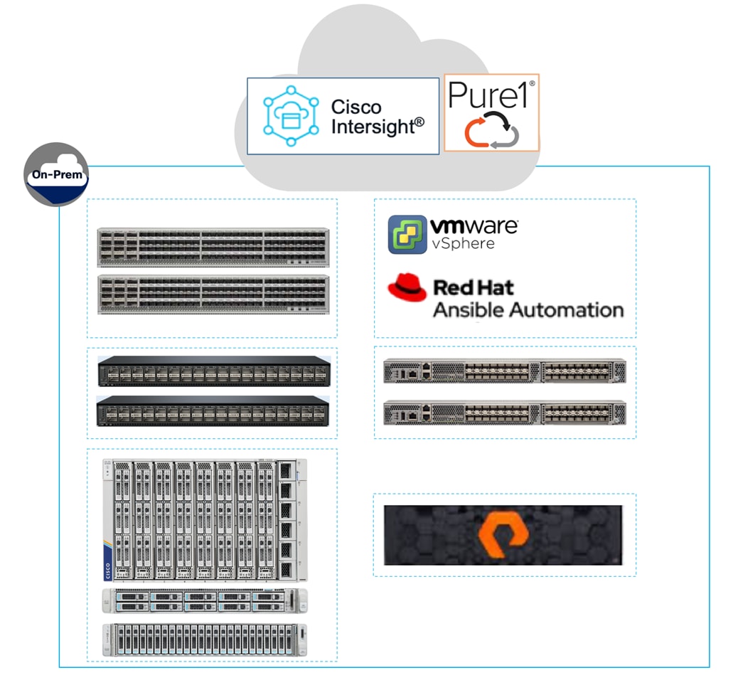
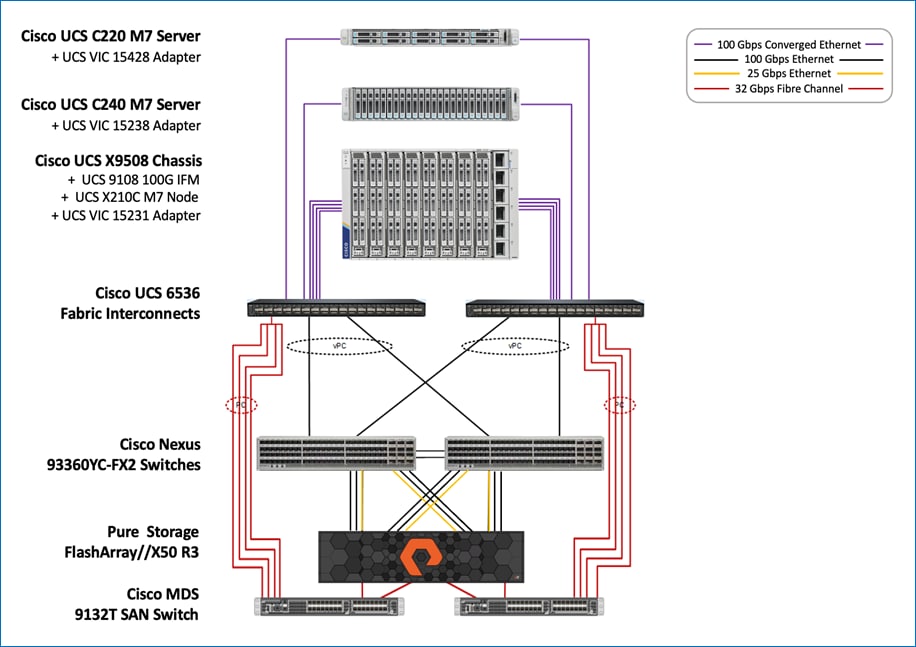
All FlashStack components are integrated and validated, so you can deploy the solution quickly and economically while minimizing risks associated with researching, designing, building, and deploying similar solutions from scratch. Each of the component families shown in Figure 1 (Cisco UCS, Cisco Nexus, Cisco MDS, and Pure Storage FlashArray systems) offers multiple options to scale-up or scale-out the infrastructure without sacrificing feature/functionality.
This FlashStack VSI solution is built using the following hardware components:
● Cisco 5th Generation Cisco UCS 6536 Fabric Interconnects providing 10/25/40/100 Gigabit Ethernet connectivity.
● Cisco UCS X9508 chassis with Cisco UCS X210c M7 compute nodes, Cisco UCS C220 M7 and Cisco UCS C240 M7 rack servers.
● Cisco UCS X210c M7 compute nodes and C-series servers are equipped with 5th Generation Cisco UCS VICs (VIC 15231, VIC 15428, VIC 15238).
● Cisco UCS 9108 100G Intelligent Fabric Module provides I/O fabric between the 6536 Fabric Interconnect and the Cisco UCS X9508 Chassis.
● Cisco Nexus 93360YC-FX2 switches running NX-OS providing high-speed 100GbE connectivity.
● Cisco MDS 9132T SAN switches providing 32Gb FC and FC-NVMe connectivity between ESXi hosts and Pure Storage.
● Pure Storage FlashArray//X50 R3 storage with 32Gb FC connectivity to Cisco MDS switching fabric, and 25GbE/100GbE connectivity to Cisco Nexus switching fabric for FA File Services and ethernet block storage (iSCSI, NVMe-TCP, NVMe-RoCEv2).
The software components in the solution include:
● Cisco Intersight SaaS platform to deploy, maintain, and support the FlashStack components from the cloud.
● Cisco Intersight Assist virtual appliance to connect the Pure Storage FlashArray, VMware vCenter, Cisco Nexus and MDS switches to Cisco Intersight.
● VMware vCenter 8.0 to manage the VMware vSphere 8.0 virtual environment.
Cisco Unified Computing System X-Series
The Cisco Unified Computing System (Cisco UCS) X-Series is a modular, next-generation data center platform that builds upon the unique architecture and advantages of the previous Cisco UCS 5108 system but with the following key enhancements that simplify IT operations:
● Cloud-managed infrastructure: With Cisco UCS X-Series, the management of the network infrastructure is moved to the cloud, making it easier and simpler for IT teams to respond quickly and at scale to meet the needs of your business. The Cisco Intersight cloud-operations platform allows you to adapt the resources of the Cisco UCS X-Series Modular System to meet the specific requirements of a workload. Additionally, you can seamlessly integrate third-party devices such as Pure Storage and VMware vCenter. This integration also enables global visibility, monitoring, optimization, and orchestration for all your applications and infrastructure.
● Adaptable system designed for modern applications: Today's cloud-native and hybrid applications are dynamic and unpredictable. Application and DevOps teams frequently deploy and redeploy resources to meet evolving requirements. To address this, the Cisco UCS X-Series provides an adaptable system that doesn't lock you into a fixed set of resources. It combines the density, manageability, and efficiency of blade servers with the expandability of rack servers, allowing you to consolidate multiple workloads onto a single platform. This consolidation results in improved performance, automation, and efficiency for both hybrid and traditional data center applications.
● Platform engineered for the future: The Cisco UCS X-Series is designed to adapt to emerging technologies with minimal risk. It is a modular system that can support future generations of processors, storage, nonvolatile memory, accelerators, and interconnects. This eliminates the need to purchase, configure, maintain, power, and cool separate management modules and servers. Cloud-based management through Intersight ensures automatic updates and access to new capabilities delivered through a software-as-a-service model.
● Broad support for diverse workloads: The Cisco UCS X-Series supports a broad range of workloads, reducing the need for different products which lowers support costs, training costs, and gives you more flexibility in your data center environment.
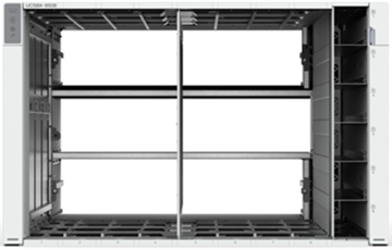
Cisco UCS X9508 Chassis
The Cisco UCS X-Series chassis is engineered to be adaptable and flexible. As shown in Figure 2, Cisco UCS X9508 chassis has only a power-distribution midplane. This innovative design provides fewer obstructions for better airflow. For I/O connectivity, vertically oriented compute nodes intersect with horizontally oriented fabric modules, allowing the chassis to support future fabric innovations. Cisco UCS X9508 Chassis’ superior packaging enables larger compute nodes, thereby providing more space for actual compute components, such as memory, GPU, drives, and accelerators. Improved airflow through the chassis enables support for higher power components, and more space allows for future thermal solutions (such as liquid cooling) without limitations.
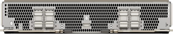
The Cisco UCS X9508 7-Rack-Unit (7RU) chassis has eight flexible slots (Figure 3). These slots can house a combination of compute nodes and a pool of future I/O resources that may include GPU accelerators, disk storage, and nonvolatile memory.
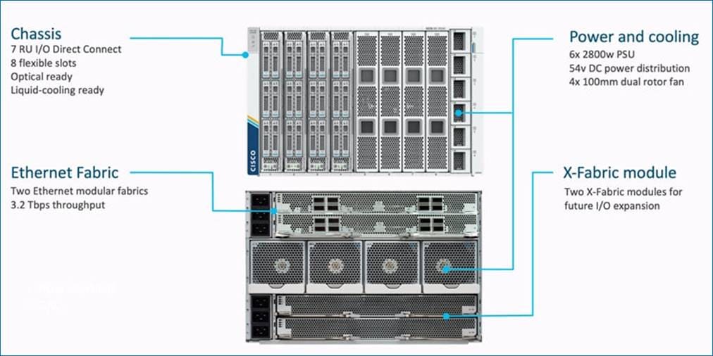
At the top rear of the chassis are two Intelligent Fabric Modules (IFMs) that connect the chassis to upstream Cisco UCS 6500 Series Fabric Interconnects. At the bottom rear of the chassis are slots ready to house future X-Fabric modules that can flexibly connect the compute nodes with I/O devices. Six 2800W Power Supply Units (PSUs) provide 54V power to the chassis with N, N+1, and N+N redundancy. A higher voltage allows efficient power delivery with less copper and reduced power loss. Efficient, 100mm, dual counter-rotating fans deliver industry-leading airflow and power efficiency, and optimized thermal algorithms enable different cooling modes to best support your environment.
Cisco UCSX 9108-100G Intelligent Fabric Modules
The Cisco UCS 9108-100G and 9108-25G Intelligent Fabric Module (IFM) brings the unified fabric into the blade server enclosure, providing connectivity between the blade servers and the fabric interconnect, simplifying diagnostics, cabling, and management.
This FlashStack solution with Cisco UCS X-Series and 5th Generation Fabric technology uses Cisco UCS 9108 100G IFM.
The Cisco UCS 9108 100G IFM connects the I/O fabric between the 6536 Fabric Interconnect and the Cisco UCS X9508 Chassis, enabling a lossless and deterministic converged fabric to connect all blades and chassis together. The fabric module is similar to a distributed line card, managed as an extension of the fabric interconnects. This approach removes switching from the chassis, reducing overall infrastructure complexity, and enabling Cisco UCS to scale to many chassis without multiplying the number of switches needed, reducing TCO, and allowing all chassis to be managed as a single, highly available management domain. The Cisco UCS 9108 100G IFM also manages the chassis environment (power supply, fans, and blades) in conjunction with the fabric interconnect. Therefore, separate chassis-management modules are not required.
The IFM plugs into the rear side of the Cisco UCS X9508 chassis. The IFM provides a data path from the chassis compute nodes to the Cisco UCS 6536 Fabric Interconnect. Up to two Intelligent Fabric Modules (IFMs) plug into the back of the Cisco UCS X9508 chassis.
The IFMs serve as line cards in the chassis and multiplex data from the compute nodes to the Fabric Interconnect (FI). They also monitor and manage chassis components such as fan units, power supplies, environmental data, LED status panel, and other chassis resources. The server compute node Keyboard-Video-Mouse (KVM) data, Serial over LAN (SoL) data, and Intelligent Platform Management Interface (IPMI) data also travel to the IFMs for monitoring and management purposes. To provide redundancy and failover, the IFMs are always used in pairs.
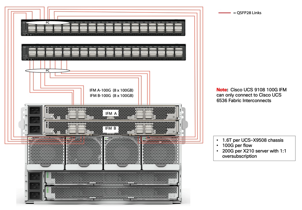
There are 8 x QSFP28 external connectors on an IFM to interface with a Cisco UCS 6536 Fabric Interconnect. The IFM internally provides 1 x 100G or 4 x 25G connections towards each Cisco UCS X210c Compute Node in Cisco UCS X9508 chassis depending on the Cisco UCS VIC deployed on the server.
The solution leverages the following Cisco UCS M7 servers in the design.
Cisco UCS X210 M7 Compute Node
The Cisco UCS X210 M7 server is a high-performance and highly scalable server designed for data centers and enterprise environments. Some of the key benefits of this server are:
● Performance: The Cisco UCS X210 M7 server is built to deliver exceptional performance. It features the latest Intel Xeon Scalable processors, providing high processing power for demanding workloads such as virtualization, database management, and analytics. The server's architecture is designed to optimize performance across a wide range of applications.
● Scalability: The Cisco UCS X210 M7 server offers excellent scalability options, allowing organizations to easily scale their computing resources as their needs grow. With support for up to eight CPUs and up to 112 DIMM slots, the server can accommodate large memory configurations and high core counts, enabling it to handle resource-intensive applications and virtualization environments.
● Memory Capacity: The server supports a large memory footprint, making it suitable for memory-intensive workloads. It can accommodate a vast amount of DDR4 DIMMs, providing a high memory capacity for applications that require significant data processing and analysis.
● Enhanced Virtualization Capabilities: The Cisco UCS X210 M7 server is designed to optimize virtualization performance. It includes features such as Intel Virtualization Technology (VT-x) and Virtual Machine Device Queues (VMDq), which improve virtual machine density and network performance in virtualized environments. These capabilities enable organizations to consolidate their workloads and achieve efficient resource utilization.
● Simplified Management: The Cisco Unified Computing System (Cisco UCS) management software provides a unified and streamlined approach to server management. The Cisco UCS Manager software allows administrators to manage multiple servers from a single interface, simplifying operations and reducing management complexity. Additionally, the server integrates with Cisco's ecosystem of management tools, providing enhanced visibility, automation, and control.
● High Availability and Reliability: The Cisco UCS X210 M7 server is built with redundancy and fault tolerance in mind. It includes features such as hot-swappable components, redundant power supplies, and redundant fans, ensuring high availability and minimizing downtime. The server's architecture is designed to support mission-critical applications that require continuous operation.
● Energy Efficiency: Cisco UCS servers are designed to be energy-efficient. The Cisco UCS X210 M7 server incorporates power management features that optimize power usage and reduce energy consumption. This not only helps organizations reduce their carbon footprint but also lowers operating costs over time.
Note: It's important to note that the specific benefits and features may vary depending on the configuration and usage scenario. Organizations should evaluate their specific requirements and consult with Cisco or their authorized resellers to determine how the Cisco UCS X210 M7 server can best meet their needs.
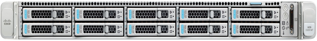
Cisco UCS C220 M7 Rack Server
The Cisco UCS C220 M7 Rack Server is a 7th generation 1-RU server in the Cisco UCS rack server portfolio. It incorporates the 4th Gen Intel Xeon Scalable Processors with 50 percent more cores per socket than previous generation server. The server supports up to 3 PCIe 4.0 slots or up to 2 PCIe 5.0 slots plus a modular LAN on motherboard (mLOM) slot and up to 3 GPUs. It also includes advanced features such as Intel Advanced Matrix Extensions (AMX), Data Streaming Accelerator (DSA), In-Memory Analytics Accelerator (IAA), and Quick Assist Technology (QAT] that will significantly improve the performance of many applications.
The Cisco UCS C-Series rack servers can be deployed as standalone servers or as part of the Cisco Unified Computing System managed by Cisco Intersight (Intersight Managed Mode) or Cisco UCS Manager. In Intersight Managed Mode, the server can connect directly to Cisco UCS 6536 Fabric Interconnects using one of the connectivity options:
● 2x100Gbps with 5th Generation Cisco UCS VIC 15238 (mLOM-based)
● 2x100Gbps with 5th Generation Cisco UCS VIC 15235 (PCIe-based)
● 4x25G to 100G breakout cables with the 5th Generation Cisco UCS VIC 15428 (mLOM-based)
● 4x25G to 100G breakout cables with the 5th Generation Cisco UCS VIC 15425 (PCIe-based)
The Cisco UCS C-Series servers can also connect to the Cisco UCS FI 6536 using the Cisco Nexus 93180YC-FX3 in FEX-mode.
The Cisco UCS C220 M7 rack server brings many new innovations to the Cisco UCS rack server portfolio. With the introduction of PCIe Gen 5.0 for high-speed I/O, a DDR5 memory bus, and expanded storage capabilities, the server delivers significant performance and efficiency gains to improve application performance.
● Supports up to two 4th Gen Intel Xeon Scalable CPUs, with up to 52 cores per socket
● Up to 32 DDR5 DIMMs for up to 4 TB of capacity using 128 GB DIMMs (16 DIMMs per socket)
● 4800 MT/s DDR5 memory plus other speeds depending on the CPU installed
● Up to 3 PCIe 4.0 slots or up to 2 PCIe 5.0 slots, plus a modular LAN on motherboard (mLOM) slot
● Support for Cisco UCS VIC 15000 Series adapters as well as third-party options
● Up to 10 SAS/SATA or NVMe disk drives:
◦ New tri-mode RAID controller1 supports SAS4 RAID or NVMe hardware RAID with optional up to four direct-attach NVMe drives
◦ Option for 10 direct-attach NVMe drives at PCIe Gen4x4 each
● M.2 boot options:
◦ Up to two 960GB SATA M.2 drives with hardware RAID
or
◦ Up to two 960GB NVMe M.2 drives with NVMe hardware RAID
● Up to three GPUs supported
Cisco UCS C240 M7 Rack Server
Similar to the Cisco UCS C220 M7 rack server, the Cisco UCS 240M7 server also expands the portfolio of Cisco UCS C-Series rack servers with a higher number of cores (60 cores), memory (8TB), number of PCIe 4.0 (8) and 5.0 (4) slots, number of GPUs (5) supported (8TB). The servers can also connect using the same options as Cisco UCS C220M7 which are:
● 2x100Gbps with 5th Generation Cisco UCS VIC 15238 (mLOM-based)
● 2x100Gbps with 5th Generation Cisco UCS VIC 15235 (PCIe-based)
● 4x25G to 100G breakout cables with the 5th Generation Cisco UCS VIC 15428 (mLOM-based)
● 4x25G to 100G breakout cables with the 5th Generation Cisco UCS VIC 15425 (PCIe-based)
The Cisco UCS C-Series servers can also connect to the FI 6536 using the Cisco Nexus 93180YC-FX3 in FEX-mode.

The features of the Cisco UCS C240 M7 server include:
● Supports up to two 4th Gen Intel Xeon Scalable CPUs, with up to 60 cores per socket
● Up to 32 DDR5 DIMMs for up to 8 TB of capacity using 256 GB DIMMs (16 DIMMs per socket)
● 4800 MT/s DDR5 memory plus other speeds depending on the CPU installed
● Up to 8 PCIe 4.0 slots or up to 4 PCIe 5.0 slots, plus a modular LAN on motherboard (mLOM) slot
● Support for Cisco UCS VIC 15000 Series adapters as well as third-party options
● Up to 28 hot-swappable Small-Form-Factor (SFF) SAS/SATA or NVMe drives (with up to 8 direct-attach NVMe drives)
◦ New tri-mode RAID controller1 supports SAS4 RAID plus NVMe hardware RAID
◦ Option for 28 direct-attach NVMe drives at PCIe Gen4x2 each
● M.2 boot options
◦ Up to two 960GB SATA M.2 drives with hardware RAID, or
◦ Up to two 960GB NVMe M.2 drives with NVMe hardware RAID
● Up to three GPUs supported
Cisco UCS Virtual Interface Cards (VICs)
Cisco UCS X210c M7 Compute Nodes and Cisco UCS C-series M7 servers support multiple Cisco UCS VIC cards. The solution uses the following Cisco UCS VIC adapters in this design.
Cisco UCS VIC 15231
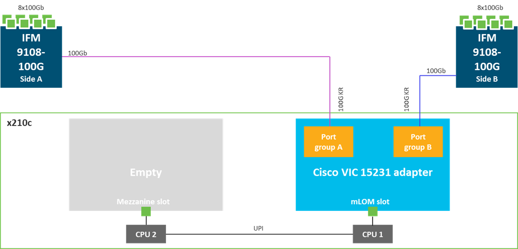
Cisco UCS VIC 15231 fits the mLOM slot in the Cisco UCS X210c Compute Node and enables up to 100 Gbps of unified fabric connectivity to each of the chassis IFMs for a total of 200 Gbps of connectivity per server. Cisco UCS VIC 15231 connectivity to the IFM and up to the fabric interconnects is delivered through 100Gbps. Cisco VIC 15231 supports 512 virtual interfaces (both FCoE and Ethernet) along with the latest networking innovations such as NVMeoF over FC or TCP, VxLAN/NVGRE offload, and so forth.
The Cisco UCS C220 M7 and Cisco UCS C240 M7 rack servers used in this design supports multiple Cisco UCS VIC cards. This design uses the Cisco UCS VIC 15428 adapter on the Cisco UCS 220 M7 server and Cisco UCS VIC 15238 adapter on the Cisco UCS 240 M7 server.
Cisco UCS VIC 15428
The Cisco UCS VIC 15428 is a quad-port small-form-factor pluggable (SFP+/SFP28/SFP56) mLOM card designed for Cisco UCS C-Series M6/M7 rack servers. The card supports 10/25/50-Gbps Ethernet or FCoE. The card can present PCIe standards-compliant interfaces to the host, and these can be dynamically configured as either NICs or HBAs.
When a Cisco UCS rack server with a Cisco UCS VIC 15428 is connected to a fabric interconnect (FI-6536/6400/6300), the Cisco UCS VIC 15428 is provisioned via Cisco Intersight or Cisco UCS Manager (UCSM) policies. And when the Cisco UCS rack server with Cisco UCS VIC 15428 is connected to a ToR switch such as Cisco Nexus 9000 Series, the Cisco UCS VIC 15428 is provisioned through the Cisco IMC or Cisco Intersight policies for a standalone server.
Cisco UCS VIC 15238
The Cisco UCS VIC 15238 is a dual-port quad small-form-factor pluggable (QSFP/QSFP28/QSFP56) mLOM card designed for Cisco UCS C-Series M6/M7 rack servers. The card supports 40/100/200-Gbps Ethernet or FCoE. The card can present PCIe standards-compliant interfaces to the host, and these can be dynamically configured as either NICs or HBAs.
When a Cisco UCS rack server with Cisco UCS VIC 15238 is connected to a Cisco UCS Fabric Interconnect (FI-6536/6300), the Cisco UCS VIC 15238 is provisioned through Cisco Intersight (IMM) or Cisco UCS Manager (UCSM) policies. And when the Cisco UCS rack server with Cisco UCS VIC 15238 is connected to a ToR switch such as Cisco Nexus 9000 Series, the Cisco UCS VIC 15238 is provisioned through the Cisco IMC or Intersight policies for a Cisco UCS standalone server.
The Cisco UCS Fabric Interconnect (FI) is an integral part of the Cisco Unified Computing System, providing both network connectivity and management capabilities for the system. Depending on the model chosen, the Cisco UCS Fabric Interconnect offers line-rate, low-latency, lossless 10 Gigabit, 25 Gigabit, 40 Gigabit, or 100 Gigabit Ethernet, Fibre Channel over Ethernet (FCoE) and Fibre Channel connectivity. The Cisco UCS Fabric Interconnects provide a single point for connectivity, providing both the LAN and SAN connectivity for all servers connected to it. They’re typically deployed as an active/active pair, integrating all servers (compute nodes, rack servers) into a single domain, and managed remotely from the cloud using Cisco Intersight.
Note: The Cisco UCS 6536 Fabric Interconnects can only be managed in Intersight Managed Mode (IMM).
Cisco UCS FIs provide a single unified fabric with low-latency, lossless, cut-through forwarding of all LAN, SAN, and management traffic to and from the servers connected to it.

The Cisco UCS 6536 utilized in this FlashStack VSI design is a 36-port Fabric Interconnect. This single RU device includes up to 36 10/25/40/100 Gbps Ethernet ports, 16 8/16/32-Gbps Fibre Channel ports via 4 128 Gbps to 4x32 Gbps breakouts on ports 33-36. All 36 ports support breakout cables or QSA interfaces.
The Cisco Intersight platform is a Software-as-a-Service (SaaS) infrastructure lifecycle management platform that delivers simplified configuration, deployment, maintenance, and support. The Cisco Intersight platform is designed to be modular, so you can adopt services based on your individual requirements. The platform significantly simplifies IT operations by bridging applications with infrastructure, providing visibility and management from bare-metal servers and hypervisors to serverless applications, thereby reducing costs and mitigating risk. This unified SaaS platform uses a unified Open API design that natively integrates with third-party platforms and tools.
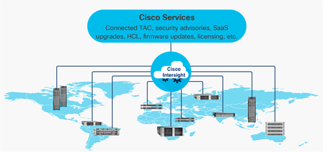
The main benefits of Cisco Intersight infrastructure services are as follows:
● Simplify daily operations by automating many daily manual tasks
● Combine the convenience of a SaaS platform with the capability to connect from anywhere and manage infrastructure through a browser or mobile app
● Stay ahead of problems and accelerate trouble resolution through advanced support capabilities
● Gain global visibility of infrastructure health and status along with advanced management and support capabilities
● Upgrade to add workload optimization and Kubernetes services when needed
Intersight Virtual Appliance and Private Virtual Appliance
In addition to the SaaS deployment model running on Intersight.com, on-premises options can be purchased separately. The Cisco Intersight Virtual Appliance and Cisco Intersight Private Virtual Appliance are available for organizations that have additional data locality or security requirements for managing systems. The Cisco Intersight Virtual Appliance delivers the management features of the Cisco Intersight platform in an easy-to-deploy VMware Open Virtualization Appliance (OVA) or Microsoft Hyper-V Server virtual machine that allows you to control the system details that leave your premises. The Cisco Intersight Private Virtual Appliance is provided in a form factor specifically designed for users who operate in disconnected (air gap) environments. The Private Virtual Appliance requires no connection to public networks or back to Cisco to operate.
Intersight Assist
Cisco Intersight is a pow management platform that enables the centralized control of diverse infrastructure components, including both 3rd party infrastructure such as Pure Storage and VMware vCenter, as well as non-Cisco UCS infrastructure like Cisco MDS and Cisco Nexus switches. With Cisco Intersight, you can have a comprehensive, global, and consolidated view of your entire infrastructure from one place.
To facilitate the management of these components, Cisco UCS infrastructure comes equipped with a Device Connector, which establishes an outbound HTTPS connection to Cisco Intersight in the cloud. By provisioning the endpoint as a target in Intersight using its Device Id and Claim Code, it can be claimed and managed from the Intersight platform. However, non-Cisco UCS infrastructure do not ship with a Device Connector, and therefore requires a different connection mechanism. This is where Cisco Intersight Assist comes into play. Cisco Intersight Assist provides that connection mechanism, enabling you to add and manage devices (supported) from Cisco Intersight.
Cisco Intersight Assist is a Virtual Appliance that can be deployed within an enterprise network. It serves as a proxy, enabling the connection and management of third-party and non- Cisco UCS infrastructure components. For each supported endpoint, Intersight Assist ships with an endpoint connector (for example, VMware vCenter or Pure Storage Connector) that communicates with the endpoint using REST APIs. Additionally, it incorporates a device connector that communicates with Cisco Intersight. By leveraging Intersight Assist, the supported endpoints can be claimed as targets in Cisco Intersight. The claiming process involves claiming Intersight Assist as a target endpoint in Intersight and then using this to claim other endpoint devices with the Claim Through Intersight Assist option.
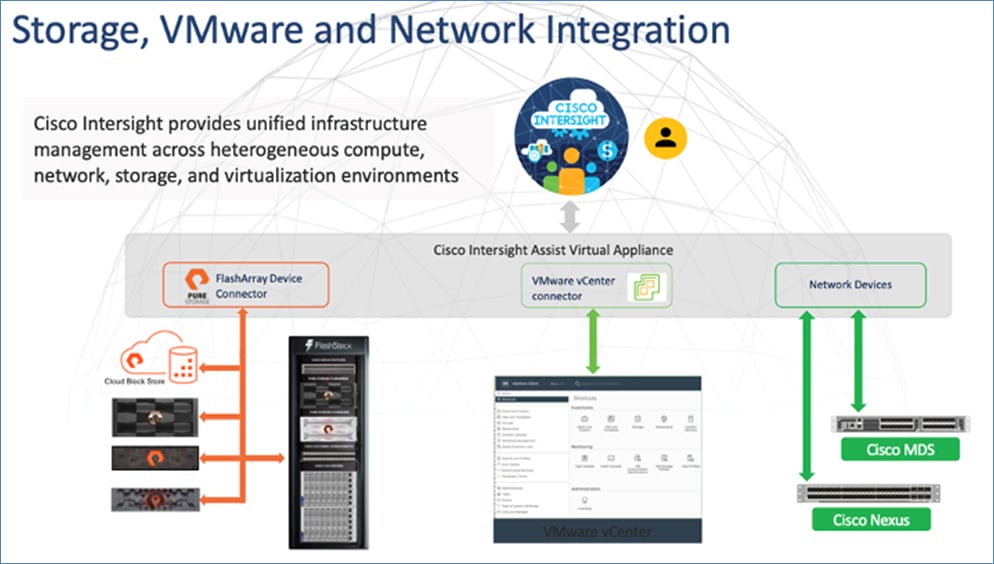
In the context of the FlashStack solution, the following third-party and non-Cisco UCS infrastructure components can be claimed and managed from Intersight through the assistance of Cisco Intersight Assist:
● VMware vCenter
● Pure Storage FlashArray
● Cisco MDS SAN switches
● Cisco Nexus switches
For more information on Cisco Intersight Assist, see: Cisco Intersight Virtual Appliance and Intersight Assist Getting Started Guide, 1.0.9
Licensing Requirements
The Cisco Intersight platform uses a subscription-based license with multiple tiers. You can purchase a subscription duration of one, three, or five years and choose the required Cisco UCS server volume tier for the selected subscription duration. Each Cisco endpoint automatically includes a Cisco Intersight Base license at no additional cost when you access the Cisco Intersight portal and claim a device. You can purchase any of the following higher tier Cisco Intersight licenses using the Cisco ordering tool:
● Cisco Intersight Essentials: Essentials includes all the functions of the Base license plus additional features, including Cisco UCS Central Software and Cisco Integrated Management Controller (IMC) supervisor entitlement, policy-based configuration with server profiles, firmware management, and evaluation of compatibility with the Cisco Hardware Compatibility List (HCL).
● Cisco Intersight Advantage: Advantage offers all the features and functions of Essentials and includes storage widgets and cross-domain inventory correlation across compute, storage, and virtual environments (VMWare ESXi). It also includes OS installation for supported Cisco UCS platforms. Intersight Orchestrator, which provides orchestration across Cisco UCS and third-party systems.
Intersight Managed Mode
The Cisco UCS 6536 Fabric Interconnect is managed through Cisco Intersight. The Cisco UCS 6536 Fabric Interconnect supports Intersight Managed Mode, which enables full manageability of Cisco UCS elements behind the UCS 6536 FI through Cisco Intersight.
Connectivity for the Cisco UCS X9508 X-Series chassis is maintained through the Cisco UCS X9108-IFM-100G or Cisco UCS X9108-IFM-25G Intelligent Fabric Module (IFM) in each Cisco UCS X-Series chassis. Connectivity for the Cisco UCS 5108 Blade Server Chassis is maintained through the Cisco UCS 2408 Series Fabric Extenders in each Cisco UCS 5108 blade chassis. The Cisco UCS C-Series servers can directly connect to Cisco UCS 6536 Fabric Interconnect through the Cisco UCS VIC 1400 series or the Cisco UCS VIC 15000 series. The Cisco UCS C-Series servers can also connect to the Cisco UCS FI 6536 using the Cisco Nexus 93360YC-FX2 in FEX-mode.
The Cisco UCS 6536 Fabric Interconnect supports out-of-band management through a dedicated 10/100/1000-Mbps Ethernet management port, as well as in-band management. The Cisco UCS 6536 Fabric Interconnect has L1/L2 ports for maintaining high availability within the UCS domain, one USB port for saving or loading configurations, and one console port for setting the initial configuration.
Note: To support the Cisco UCS X-Series, the fabric interconnects must be configured in Intersight Managed Mode (IMM).
The Cisco Nexus 9000 Series Switches offer both modular and fixed 1/10/25/40/100 Gigabit Ethernet switch configurations with scalability up to 60 Tbps of nonblocking performance with less than five-microsecond latency, wire speed VXLAN gateway, bridging, and routing support.
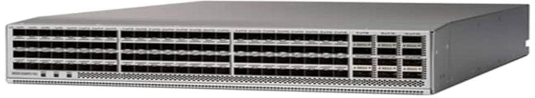
The Cisco Nexus 9000 series switch featured in this design is the Cisco Nexus 93360YC-FX2 configured in NX-OS standalone mode. NX-OS is a purpose-built datacenter operating system designed for performance, resiliency, scalability, manageability, and programmability at its foundation. It provides a robust and comprehensive feature set that meets the demanding requirements of virtualization and automation.
The Cisco Nexus 93360YC-FX2 Leaf Switch is a 2-Rack-Unit (2RU) Leaf switch that supports 7.2 Tbps of bandwidth and 2.4 bps across 96 fixed 10/25G SFP+ ports and 12 fixed 40/100G QSFP28 ports. The 96 ports of downlinks support 1/10/25-Gbps. The 12 uplinks ports can be configured as 40- and 100-Gbps ports, offering flexible migration options. The switch has FC-FEC and RS-FEC enabled for 25Gbps support over longer distances.
Cisco MDS 9132T 32G Multilayer Fabric Switch
The Cisco MDS 9132T 32G Multilayer Fabric Switch is the next generation of the highly reliable, flexible, and low-cost Cisco MDS 9100 Series switches. It combines high performance with exceptional flexibility and cost effectiveness. This powerful, compact one Rack-Unit (1RU) switch scales from 8 to 32 line-rate 32 Gbps Fibre Channel ports.
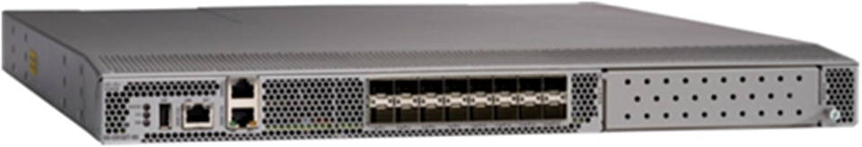
The Cisco MDS 9132T delivers advanced storage networking features and functions with ease of management and compatibility with the entire Cisco MDS 9000 family portfolio for reliable end-to-end connectivity. This switch also offers state-of-the-art SAN analytics and telemetry capabilities that have been built into this next-generation hardware platform. This new state-of-the-art technology couples the next-generation port ASIC with a fully dedicated network processing unit designed to complete analytics calculations in real time. The telemetry data extracted from the inspection of the frame headers are calculated on board (within the switch) and, using an industry-leading open format, can be streamed to any analytics-visualization platform. This switch also includes a dedicated 10/100/1000BASE-T telemetry port to maximize data delivery to any telemetry receiver, including Cisco Data Center Network Manager.
Cisco Nexus Dashboard Fabric Controller (NDFC) SAN
Cisco Nexus Dashboard Fabric Controller (NDFC) provides a complete lifecycle management and automation for Cisco NX-OS based SAN fabrics. NDFC SAN provides a single pane of glass to monitor SAN fabrics with advance analysis and end-to-end visibility. NDFC-SAN also provides management, control, automation, monitoring, visualization, and troubleshooting across a Cisco MDS-based SAN fabric. Key capabilities in the NDFC SAN include:
● Monitor SAN fabric with additional visibility into compute, virtualization, and storage layers from a single plane of glass
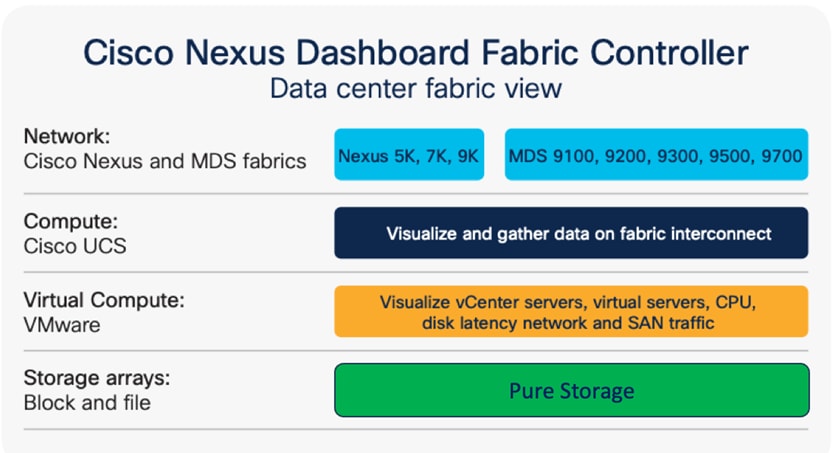
● Resolve congestion issues quickly with the use of NDFC
Slow Drain Analysis Cisco NDFC slow-drain analysis is a highly effective tool used to identify and help solve fabric level congestion in the fabric. Finding a slow-draining device in a large (or even small) SAN fabric can often be challenging. NDFC slow-drain analysis automates the often-manual process of trying to find these congestion issues by gathering data every 10 seconds from every port in the fabric. The statistics are displayed in bar charts and graphs showing fluctuation in counters and can be sorted according to switch interfaces/ port-channels and various counters.
● SAN end-to-end visibility
Cisco NDFC SAN Insights provides a dashboard with a high-level overview of ley metrics, with more granular fabric and switch level details available. It provides a fully-native and integrated SCSI and NVMe analytics engine built into the Cisco 32G and 64G MDS series switches that help administrators recognize fabric level performance and enhance link utilization to optimize their storage infrastructure. SAN analytics engine is always running in the background to find issues real-time. It also provides host level metrics, storage level metrics and, Initiator-Target-LUN (ITL) level metrics along with health score for all links and enclosures.
● Simplify, identify, and analyze all day-to-day tasks
Cisco NDFC has key features and capabilities that simplify SAN operation. It has an integrated device manager for each switch to view and configure all the relevant switch-level information. Cisco NDFC SAN provides all the switch and fabric level operations and management from VSAN, Zoning, Port Channels, Device Alias, PMON, FCIP, link diagnostics, events, switch backup, ISSUs, host path redundancy, and slow- drain analysis. Cisco NDFC provides an overall topology view, built on switch-health status and link status/bandwidth, which gives a holistic view of the storage network. From the topology view, links or even switches can be compared to see usage and health and can be used to debug or predict issues.
Cisco NDFC SAN is deployed as an app on Cisco Nexus Dashboard. A single-server instance of the virtualized Cisco Nexus Dashboard with NDFC SAN and SAN Analytics is supported. Once the Cisco MDS switches and Cisco UCS Fabric Interconnects are added with the appropriate credentials and licensing, monitoring of the SAN fabrics can begin.
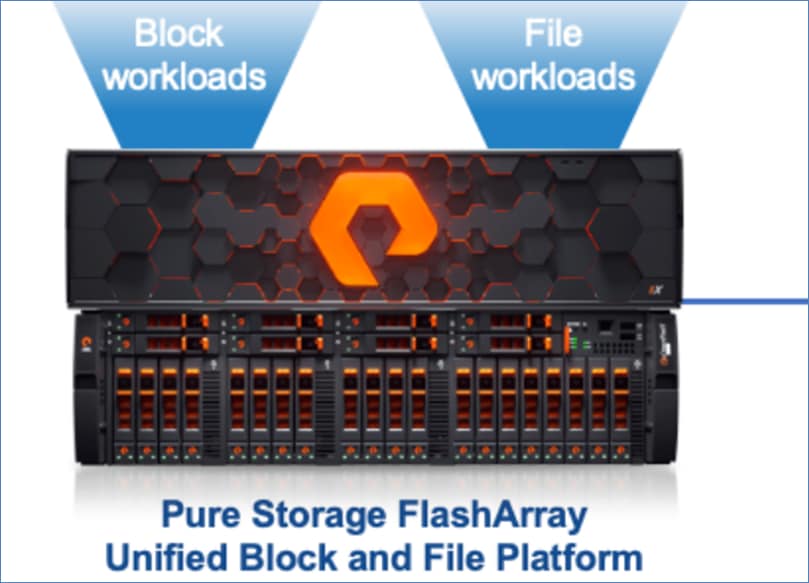
The Pure Storage FlashArray is a software-defined all-flash, all-NVMe, unified block and file storage platform designed to meet the current and future needs of modern corporate and enterprise organizations.
Pure Storage FlashArray provides the following benefits:
● Performance: Ultra-low and predictable 150us to 1ms latency for all applications. The self-optimized array is perfect for consolidating block (NVMe/NVMe-oF) and file (SMB/NFS) workloads with little to no performance impact.
● High Availability: Provides 99.9999% availability with built-in business continuity and disaster recovery across product lines while continuing to meet service-level agreements (SLAs).
● Storage Efficiency: Highly efficient 5:1 data reduction and 10:1 total efficiency provides up to 5.5PB of effective capacity in a greatly reduced footprint.
● Simplicity: Single pane of glass and AI-driven management with Pure1, combined with REST API automation to free storage administrators from time-consuming tasks. Nondisruptive updates, upgrades, and capacity expansions as well as integrated and predictive support ensure no business disruption and reduce strain on admins.
Purity for FlashArray (Purity//FA 6)
Every Pure Storage FlashArray is driven by Purity Operating Environment software. Purity//FA6 implements advanced data reduction, storage management, and flash management features, enabling you to enjoy tier 1 data services for all workloads. Purity software provides proven 99.9999-percent availability over two years, completely nondisruptive operations, 2X better data reduction, and the power and efficiency of DirectFlash. Purity also includes enterprise-grade data security, comprehensive data-protection options, and complete business continuity with an ActiveCluster multi-site stretch cluster. All these features are included with every Pure Storage array.
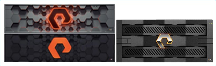
The Pure Storage FlashArray Family delivers software-defined all-flash power and reliability for businesses of every size. Pure Storage FlashArray is all-flash enterprise storage that is up to 10X faster, space and power efficient, reliable, and far simpler than other available solutions. Compared to traditional performance disk arrays, Pure Storage FlashArray costs less with total cost of ownership (TCO) savings of up to 50%. At the top of the Pure Storage FlashArray line is Pure Storage FlashArray//X—the first mainstream, 100-percent NVMe, enterprise-class all-flash array. //X represents a higher performance tier for mission-critical databases, top-of-rack flash deployments, and tier 1 application consolidation. Pure Storage FlashArray//X, at 1PB in 3RU, hundred-microsecond range latency, and GBs of bandwidth, delivers unparalleled performance density and consolidation. Pure Storage FlashArray//X is ideal for cost-effective consolidation of everything on flash, including accelerating a single database, scaling virtual desktop environments, or powering an all-flash cloud.
Pure Storage FlashArray//X R3 Specification
Table 1 lists both capacity and physical aspects of various Pure Storage FlashArray systems.
Table 1. Pure Storage FlashArray//X R3 Specifications
|
|
Capacity |
Physical |
| //X20 |
Up to 314 TB/285.4 TiB (tebibyte) effective capacity** Up to 94 TB/88 TiB raw capacity† |
3RU; 741–973 watts (nominal – peak) 95 lb. (43.1 kg) fully loaded; 5.12 x 18.94 x 29.72 in. |
| //X50 |
Up to 663 TB/602.9 TiB effective capacity** Up to 185 TB/171 TiB raw capacity† |
3RU; 868–1114 watts (nominal – peak) 95 lb. (43.1 kg) fully loaded; 5.12 x 18.94 x 29.72 in. |
| //X70 |
Up to 2286 TB/2078.9 TiB effective capacity** Up to 622 TB/544.2 TiB raw capacity† |
3RU; 1084–1344 watts (nominal – peak) 97 lb. (44.0 kg) fully loaded; 5.12 x 18.94 x 29.72 in. |
| //X90 |
Up to 3.3 PB/3003.1 TiB effective capacity** Up to 878 TB/768.3 TiB raw capacity† |
3–6RU; 1160–1446 watts (nominal – peak) 97 lb. (44 kg) fully loaded; 5.12 x 18.94 x 29.72 in. |
| DirectFlash Shelf |
Up to 1.9 PB effective capacity** Up to 512 TB/448.2 TiB raw capacity |
3RU; 460–500 watts (nominal – peak) 87.7 lb. (39.8kg) fully loaded; 5.12 x 18.94 x 29.72 in. |
** Effective capacity assumes high availability, RAID, and metadata overhead, GB-to-GiB conversion, and includes the benefit of data reduction with always-on inline deduplication, compression, and pattern removal. Average data reduction is calculated at 5-to-1 and does not include thin provisioning.
† Array accepts Pure Storage DirectFlash Shelf and/or Pure.
Table 2 lists the various connectivity options using both onboard and host I/O cards.
Table 2. Pure Storage FlashArray //X Connectivity
| Onboard ports |
Host I/O cards |
|
| Two 1-/10-/25-GE |
2-port 10GBASE-T Ethernet |
2-port 25-/50 or 100-Gb |
| Two 1-/10-/25-GE replication |
2-port 1/10/25 Gb Ethernet |
2-port 16-/32-Gb Fibre Channel |
| Two 1-Gb management ports |
2-port 40 Gb Ethernet |
4-port 16-/32-Gb Fibre Channel |
Pure1, a cloud-based management, analytics, and support platform, expands the self-managing, plug-n-play design of Pure all-flash arrays with the machine learning predictive analytics and continuous scanning of Pure1 Meta to enable an effortless, worry-free data platform.
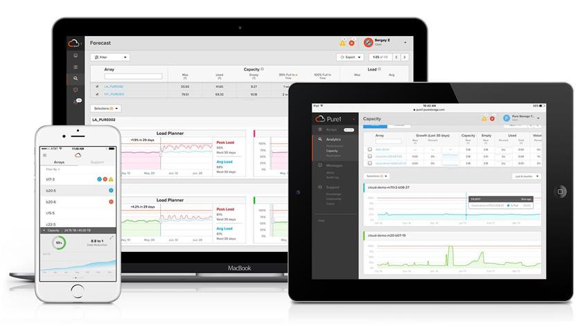
Pure1 Manage is a SaaS-based offering that allows you to manage your array from any browser or from the Pure1 Mobile App with nothing extra to purchase, deploy, or maintain. From a single dashboard, you can manage all arrays and have full storage health and performance visibility.
Pure1 Analyze delivers true performance forecasting, giving you complete visibility into the performance and capacity needs of your arrays, now and in the future. Performance forecasting enables intelligent consolidation and workload optimization.
Pure1 Capacity/Planning/Reporting
This feature of Pure1 is a set of tools that you can leverage to understand how your environment is performing, how your storage environment is growing, and how to present capacity and performance planning materials to leadership.
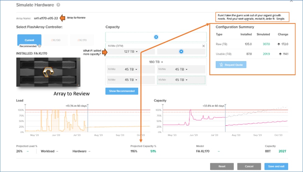
Pure1 takes the sizing of future upgrades for capacity and gives you the power to understand your organic scaling needs.
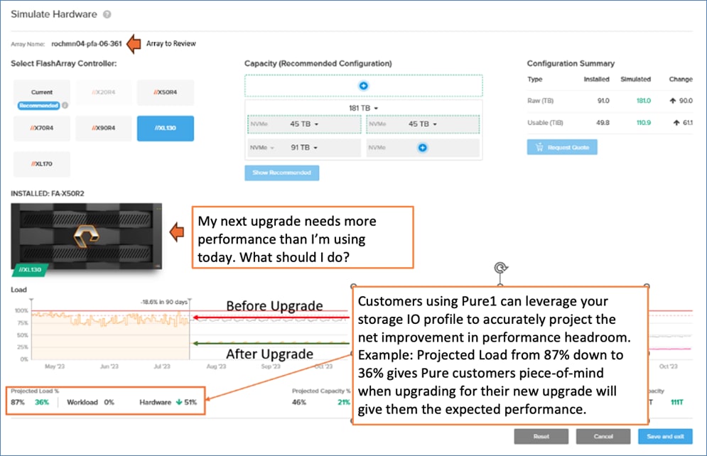
Using Pure1, you can determine your real workload performance characteristics to model your next upgrade to ensure the storage platform model you require will do the job. Easy. No Surprises.
Pure1 Support
Pure Storage support team with the predictive intelligence of Pure1 Meta delivers unrivaled support that’s a key component in Pure Storage FlashArray 99.9999% availability. Some of the issues are identified and fixed without any intervention.
The foundation of Pure1 services, Pure1 Meta is global intelligence built from a massive collection of storage array health and performance data. By continuously scanning call-home telemetry from Pure’s installed base, Pure1 Meta uses machine learning predictive analytics to help resolve potential issues, optimize workloads, and provide accurate forecasting. Meta is always expanding and refining what it knows about array performance and health.
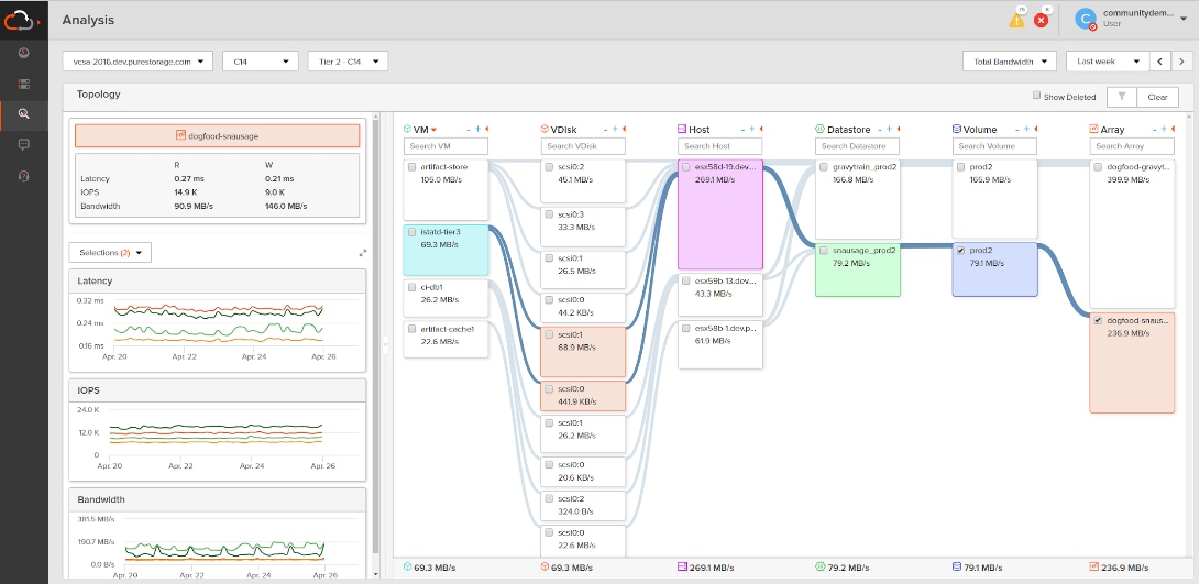
Pure1 VM Analytics
Pure1 helps you narrow down the troubleshooting steps in your virtualized environment. VM Analytics provides you with a visual representation of the IO path from the VM all the way through to the Pure Storage FlashArray. Other tools and features guide you through identifying where an issue might be occurring in order to help eliminate potential candidates for a problem.
VM Analytics doesn’t only help when there’s a problem. The visualization allows you to identify which volumes and arrays particular applications are running on. This brings the whole environment into a more manageable domain.
Pure portable snapshots provide simple, built-in, local and cloud protection for Pure Storage FlashArrays. Purity Snapshots enable free movement of space-efficient copies between Pure Storage FlashArrays, to FlashBlade, to 3rd party NFS servers, and to the cloud. Pure’s portable snapshot technology encapsulates metadata along with data into the snapshot, making the snapshot portable, so it can be offloaded from a Pure Storage FlashArray to the cloud in a format that is recoverable to any Pure Storage FlashArray.
Benefits
CloudSnap is a self-backup technology built into Pure Storage FlashArray. It does not require the purchase of additional backup software or hardware, nor is there a need to learn and use an additional management interface. CloudSnap is natively managed via Pure Storage FlashArray’s GUI, CLI, and REST interfaces and is integrated with the Pure1 Snapshot Catalog. Since Pure Storage FlashArray connects to AWS via https, data is encrypted in transit and stored in an encrypted format in the S3 bucket using server-side encryption. Since CloudSnap was built from scratch for Pure Storage FlashArray, it is deeply integrated with the Purity Operating Environment, resulting in highly efficient operation. A few examples of the efficiency of CloudSnap:
● CloudSnap preserves data compression on the wire, and in the S3 bucket, saving network bandwidth and increasing storage space efficiency.
● CloudSnap preserves data reduction across snapshots of a volume. After offloading the initial baseline snapshot of a volume, it only sends delta changes for subsequent snaps of the same volume. The snapshot differencing engine runs within the Purity Operating Environment in Pure Storage FlashArray and uses a local copy of the previous snapshot to compute the delta changes. Therefore, there is no back and forth network traffic between Pure Storage FlashArray and the cloud to compute deltas between snapshots, further reducing network congestion and data access costs in the cloud.
● CloudSnap knows which data blocks already exist on Pure Storage FlashArray, so during restores it only pulls back missing data blocks to rebuild the complete snapshot on Pure Storage FlashArray. In addition, CloudSnap uses dedupe preserving restores, so when data is restored from the offload target to Pure Storage FlashArray, it is deduped to save space on Pure Storage FlashArray.
The highly efficient operation of CloudSnap provides the following benefits:
● Less space is consumed in the S3 bucket
● Network utilization is minimized
● Backup windows are much smaller
● Data retrieval costs from the S3 bucket are lower
Data and Infrastructure Security
FlashStack can provide a "Defense in Depth" layered security strategy, which protects your valuable data at every point across your infrastructure. Along with SafeMode Snapshots and our ecosystem of top Data Protection partners, you can leverage Cisco's world-renowned cybersecurity suite to build a complete data protection and security solution. Pure Storage SafeMode is now enabled by default, ensuring that you have protection of your strategic data sets with immutable encryption, providing this safeguard out of the box.
FlashArray Unified Block and File Platform
The intelligent design of the Pure Storage FlashArray Unified Block and File Platform delivers low latency flash storage for consolidation of block and file workloads without compromising simplicity, scalability, performance, This contrasts with legacy scale-up and scale-out storage arrays with bolt-on multiprotocol support that add additional layers of complexity and limit functionality and flexibility.
Pure Storage FlashArray File Services are integrated into the Purity FA6 operating system to deliver scale-up file services (SMB, NFS) based on a file system, rather than one built on top of block devices or volumes. As such, it does not require a gateway and uses a shared storage pool for both block and file, with the same deduplication and compression that is used for block storage. File services provide directory-level snapshots, performance, and space monitoring with managed directories and export policies built into GUI, CLI, and REST API management interfaces.
Pure Storage FlashArray Unified Block and File Platform provides you with significant savings and benefits as outlined below:
● Unified storage pool architecture – Pure Storage FlashArray helps to unify operations and eliminate data silos by supporting all block and file workloads from a single unified pool of global storage. The shared storage pool design enables file shares and archives to reside and be managed alongside production workloads with no tradeoffs. Data is stored efficiently and with the optimized context for block or file, making it an ideal system to simultaneously manage and deliver efficient storage operations for LUNs, file systems, and VMs.
● Simplified management experience – Pure Storage provides a single, simple management interface with an intuitive UI for block and file as well as the ability to automate file services with the CLI and REST API. Because there are no gateways or appliances to manage, and file systems are not built on top of volumes or aggregates, there were no additional prerequisite steps required to create a file system. Admins benefit from the ability to manage and grow block and file data at the granularity of the data entity rather than being tied to the limitations of any underlying constructs.
● Storage Efficiency – With the Pure Storage FlashArray Unified Block and File Platform, you can snapshot a directory, LUN, or VM rather than a whole volume or aggregate. From a capacity standpoint, this reduces the cost per usable GB for a storage array. It also reduces the management complexity of having to manage the copy as a whole rather than individually. The global dedupe and compression available for file and block workloads enables further efficiencies.
● Flash storage for file workloads – Pure Storage FlashArray provides predictable low latency operations for all block and file workloads without limitation and without impact. While end-users are typically used to some degree of lag waiting for file-based applications, user directories, and content repositories to perform searches and functions, flash performance results in significantly faster time to load documents, files, and images as well as an overall better application responsiveness and end-user experience. This also enables file storage to be considered for next-generation performance-sensitive applications, such as analytics and video use cases.
● Improved visibility and reporting – Administrators of traditional unified storage arrays often have limited visibility into the underlying resources currently being used by file services at a granular level, which makes it difficult to predict capacity growth or monitor costs and performance without managing complicated scripts and consolidating information from various interfaces. Pure Storage FlashArray provides built-in and real-time visibility into all block and file constructs with the same information provided for both block and file services on Pure1, making it easy to monitor capacity and performance utilization as well as predict growth, going forward. Pure1 predictive analytics provides proactive support and helps identify and remediate issues before they happen.
● Sustainability – With sustainability being a top priority for organizations, consolidating and running block and file workloads more efficiently on Pure Storage FlashArray results in a dramatically reduced footprint, with substantially lower power and cooling requirements.
● Reduced risk of downtime – Pure Storage FlashArray architecture is designed to deliver 100% performance capabilities when performing software updates, upgrading hardware, and scaling capacity unlike traditional architectures that require downtime or runs in a degraded state during software updates.
● Guaranteed innovation and business agility – The design of traditional storage systems limits innovation because of full forklift upgrades or time-consuming data migrations that are generally required to take advantage of the latest innovations in storage controller, interconnect, and disk technologies. Your deployments are upgraded in place without forklift upgrades or disruption to service as new technology is made available – Pure software updates with new capabilities are released at a regular quarterly cadence. Also, organizations can use a Pure Evergreen//Forever subscription to take advantage of the latest improvements in hardware technology over time, without having to invest time to research, plan, or purchase new storage arrays.
● Improved security and ransomware protection – Pure Storage offers improved security with encryption of data to better meet regulations, and Pure SafeMode snapshots cost-effectively protect both block and file data against ransomware events and unintentional deletion, while making it possible to quickly remediate any events that do happen, without impact to operations.
VMware vSphere is a virtualization platform for holistically managing large collections of infrastructures (resources including CPUs, storage, and networking) as a seamless, versatile, and dynamic operating environment. Unlike traditional operating systems that manage an individual machine, VMware vSphere aggregates the infrastructure of an entire data center to create a single powerhouse with resources that can be allocated quickly and dynamically to any application in need.
VMware vSphere 8.0 has several improvements and simplifications including, but not limited to:
● Limits with VMware vSphere 8.0 have been increased including number of GPU devices is increased to 8, the number of ESXi hosts that can be managed by Lifecycle Manager is increased from 400 to 1000, the maximum number of VMs per cluster is increased from 8,000 to 10,000, and the number of VM DirectPath I/O devices per host is increased from 8 to 32.
● Security improvements including adding an SSH timeout on ESXi hosts, a TPM Provisioning policy allowing a vTPM to be replaced when cloning VMs, and TLS 1.2 as the minimum supported TLS version.
● Implementation of VMware vMotion Unified Data Transport (UDT) to significantly reduce the time to storage migrate powered off virtual machines.
● Lifecycle Management improvements including VMware vSphere Configuration Profiles as a new alternative to VMware Host Profiles, staging cluster images and remediating up to 10 ESXi hosts in parallel instead of one at a time.
● New Virtual Hardware in VM hardware version 20 supporting the latest guest operating systems, including Windows 11.
● Distributed Resource Scheduler and vMotion improvements.
● Implementation of the VMware Balanced Power Management Policy on each server, which reduces energy consumption with minimal performance compromise.
● Implementation of VMware Distributed Power Management, which along with configuration of the Intelligent Platform Management Interface (IPMI) on each Cisco UCS server allows a VMware host cluster to reduce its power consumption by powering hosts on and off based on cluster resource utilization.
For more information about VMware vSphere and its components, go to: https://www.vmware.com/products/vsphere.html.
VMware vCenter
VMware vCenter Server provides unified management of all hosts and VMs from a single console and aggregates performance monitoring of clusters, hosts, and VMs. VMware vCenter Server gives administrators a deep insight into the status and configuration of compute clusters, hosts, VMs, storage, the guest OS, and other critical components of a virtual infrastructure. VMware vCenter manages the rich set of features available in a VMware vSphere environment.
Ansible is a simple, secure and powerful automation tool that is community-powered and backed by Red Hat, enabling Enterprise IT teams to automate both infrastructure and systems. With engineering and support from Red Hat, Ansible provides a common tool that Enterprises can use for a range of automation efforts. Ansible is leveraged in the FlashStack solutions to automate the provisioning of the compute, storage, network (LAN, SAN) and the virtualization layers of the infrastructure. Ansible playbooks are used to configure the different components (Cisco UCS, Cisco Nexus switches, Cisco MDS switches, Pure Storage FlashArray and VMware vSphere) in the solution. For each CVD, the Ansible playbooks are made available in the UCS Solutions GitHub repository in addition to the deployment guide(s) that show how the same deployment can be done manually. You can access and use the playbooks to automate their own FlashStack deployments when they’re released (shortly after the release of this design guide).
Solution Design
This chapter contains the following:
● Resilient design across all layers of the infrastructure with no single point of failure.
● Scalable design with the ability to independently add compute, storage, and network bandwidth as needed.
● Modular design where sub-system components and resources can be changed, expanded, or upgraded as needed. Also, the design can be replicated as a unit to meet growth and expansion requirements.
● Flexible design with design options for the different sub-systems in the solution, including the individual components used, storage configuration and connectivity options.
● Best-practices based design, incorporating design, technology, and product best practices.
● Simplify deployments through automation and make the solution available as Infrastructure as Code (IaC).
● Simplify operations using SaaS management where possible.
The high-level design of the FlashStack VSI solution using Unified Block and File is shown in Figure 11.
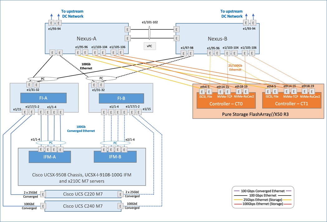
The FlashStack VSI solution for enterprise data centers delivers a 100GbE solution with 32Gb FC and FC-NVMe based storage, iSCSI, NVMe-TCP, and NVMe-RoCEv2 based IP/Ethernet storage, and NFS storage. The solution includes the latest generation of Cisco UCS hardware running VMware vSphere 8.0. The solution incorporates design, technology, and product best practices to deliver a highly scalable and available architecture with no single point of failure. The compute, storage, network, and virtualization layers of the end-to-end design is built using the following components.
● Cisco UCS X9508 server chassis with 2 x Cisco UCS X9108-100G Intelligent Fabric Modules (IFMs) where 4 x 100GbE ports on each IFM connect to a pair of Cisco UCS Fabric Interconnects to provide upstream connectivity and all networks within and outside the Enterprise data center, including external networks.
● Cisco UCS X210c M7 compute nodes using 2 x 4th generation Intel Xeon Scalable processors with 256GB of DDR5 memory that can be increased up to a max of 8TB. The server is equipped with a Cisco UCS VIC 15231 network adaptor in the modular LAN On Motherboard (mLOM) slot and provides up to 200Gbps (2x100Gbps) of unified fabric connectivity from each compute node to the 100G Intelligent Fabric Modules (IFMs) on the Cisco UCS X-Series chassis.
● Pair of Cisco UCS 6536 Fabric Interconnects (FIs) provides line-rate, low-latency, lossless connectivity for LAN, SAN and management traffic from the Cisco UCS X-Series and Cisco UCS C-Series servers to Pure Storage and other upstream and external networks. The Cisco Fabric Interconnects provide:
◦ 4 x 32Gb FC connectivity to a Pure Storage FlashArray//X50 R3 through a pair of Cisco MDS switches.
◦ 2x100GbE uplink network connectivity to a pair of Cisco Nexus switches deployed in a vPC configuration and provide uplink connectivity to other internal and external networks.
● Pair of Cisco Nexus 93360YC-FX2 switches in NX-OS mode provide upstream connectivity to the Cisco UCS 6536FIs, enabling 100Gbps or higher speeds for connecting the FlashStack compute and storage infrastructure to other parts of an Enterprise’s internal and external networks as needed. The Cisco Nexus switches also connect to Pure Storage FlashArray using 25GbE and 100GbE to connect to FA file and block storage.
● Pair of Cisco MDS 9132T FC switches provides 32Gbps Fibre Channel connectivity to a SAN fabric with consistent low-latency performance using a chip-integrated non-blocking arbitration. MDS can operate in either switch mode or NPV mode and includes a dedicated Network Processing Unit (NPU) per port for real-time analytics calculations. The switch can inspect FC and SCSI headers at wire speed on every flow and analyze the flows on the switch itself. By using an industry-leading open format, the telemetry data can then be streamed to any analytics-visualization platform. This switch also includes a dedicated 10/100/1000BASE-T telemetry port to maximize data delivery to any telemetry receiver including Cisco Data Center Network Manager. Note that since this solution uses Cisco UCS 6536FIs running in NPV mode, the MDS switches will not be used in NPV mode in this CVD. Instead, the MDS switches will be deployed in Fibre Channel switching mode with NPIV mode.
● Pure Storage FlashArray//X50 R3 connects to the Cisco MDS 9132T switches using 32-Gbps Fibre Channel connections for Fibre Channel SAN connectivity. The Pure Storage FlashArray//X50 R3 also connects to the Cisco Nexus 93360YC-FX2 switches using 25/100Gb Ethernet ports for FA file (NFS) and block (iSCSI, NVMe-TCP, NVMe-RoCEv2) services.
● VMware vSphere 8.0 is deployed on the Cisco UCS X210M7, C220 M7 and C240 M7 servers to host virtualized workloads.
● Cisco Intersight in Intersight Managed Mode (IMM) will manage the infrastructure from the cloud.
The FlashStack VSI is designed to be highly available with redundancy at all layers of the stack (compute, storage, networking) including cabling and connectivity between components in the solution.
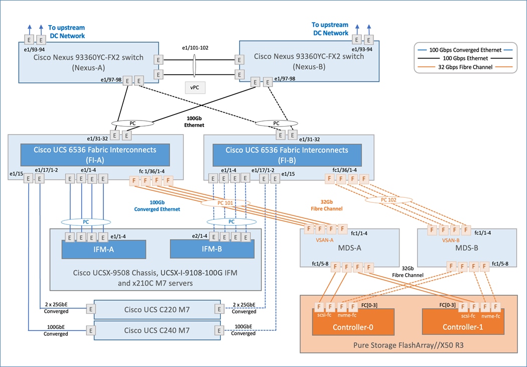
The detailed connectivity design for the FlashStack VSI solution using FA Unified Block and File is shown in Figures 12 and 13.
Compute Infrastructure Design
The compute infrastructure in FlashStack VSI solution consists of the following:
● Cisco UCS M7 servers – either compute nodes (Cisco UCSX-210M7) or rack servers (Cisco UCS C220 M7, C240 M7)
● Cisco UCS X-Series chassis (Cisco UCSX-9508) with Intelligent Fabric Modules (Cisco UCSX-I-9108-100G)
● Cisco UCS Fabric Interconnects (Cisco UCS-FI-6536)
Cisco UCS Compute Nodes/Servers
A Cisco UCS X-Series chassis with the latest Cisco UCS X210 M7 compute nodes and Cisco UCS C-Series rack servers (Cisco UCS C220 M7, Cisco UCS C240M7). The Cisco UCS servers connect to a pair of Cisco UCS 6536 Fabric Interconnects to provide a highly available and scalable design as outlined below.
● Cisco UCS X-Series compute nodes connect to the Fabric Interconnects through a pair of redundant 100GbE Intelligent Fabric Modules (IFM) in the Cisco UCS X9508 chassis. The IFMs serve as a lossless and deterministic converged I/O fabric to connect the compute nodes in the chassis to the Cisco UCS Fabric Interconnects. IFMs are physically located in the back of the Cisco UCS X-Series chassis and provide a single point of connectivity for all servers in the chassis. Up to two IFMs can be deployed in a given Cisco UCS X-Series chassis IFMs simplify the cabling, management and troubleshooting of the compute infrastructure. The IFMs uses multiple links in a port-channel bundle to connect to the Fabric Interconnects to provide redundancy and higher aggregate bandwidth. In this design, a pair of Cisco UCSX 9108-100G IFMs are deployed, with each IFM (IFM-A, IFM-B) connecting to the corresponding Fabric Interconnect (FI-A, FI-B) using 4 x 100GbE links to provide an aggregate uplink bandwidth of 800Gbps per chassis for all traffic to and from the servers. For higher uplink bandwidth, all eight ports of the IFM can be used for a maximum uplink bandwidth of 1.6Tbps. Each IFM also connects internally to each compute node in the chassis, providing either 1 x 100G or 4 x 25G for a total of 100Gbps of bandwidth per server depending on the VIC deployed on the server. If the servers use a combination of 100G VICs and 25G VICs, then the connectivity will be a combination of 1x 100G and 4 x 25G depending on the VIC.
● Cisco UCS C-Series rack serves connect directly to the fabric interconnects using multiple 25GbE (Cisco UCS C220 M7) and 100GbE links (C240 M7) using 25G and 100G VICs.
Cisco UCS Fabric Interconnects
The Cisco UCS 6536 Fabric Interconnects provide SAN, LAN, and management connectivity to and from the Cisco UCS Servers. The Cisco UCS/ESXi hosts, and the workloads hosted on the infrastructure use the Fabric Interconnects to access fibre channel and IP/Ethernet storage on Pure Storage and for reachability to Enterprise internal networks and for networks outside the Enterprise (for example, Cisco Intersight, Pure Storage Pure1).
In this design, the Cisco UCS Fabric Interconnects and the servers attached to it are managed remotely from the cloud in Intersight Managed Mode (IMM). IMM enables the Cisco UCS infrastructure to be completely managed from Cisco Intersight, including port configuration, firmware management, troubleshooting and server configuration using pools, policies, profiles, and server profile templates.
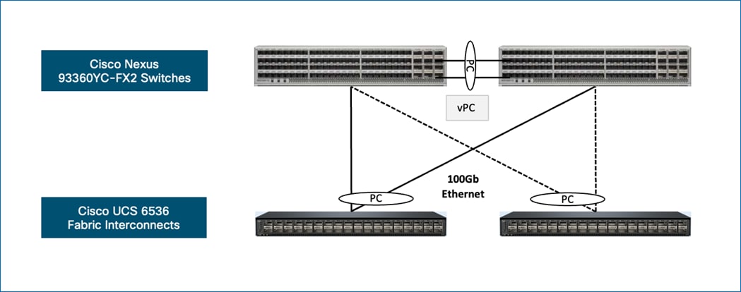
For upstream connectivity to other parts of the enterprise network, including connectivity to the larger data center, and other internal and external networks, the Cisco UCS 6536 FIs connect to a pair of Cisco Nexus 93360YC-FX2 switches. The Cisco Nexus 93360YC-FX2 switches provide the core IP/Ethernet (Layer 3/Layer 2) networking in this design. For high availability, each FI is dual-homed to both Cisco Nexus switches using 2 x 100GbE links in a port-channel (PC) configuration. For higher uplink bandwidth, additional links can be added to the port channel as needed. The Cisco Nexus switches are configured as virtual port channels (VPCs).
For storage connectivity to Pure Storage FlashArray, the FlashStack solution supports both fibre channel and IP/Ethernet:
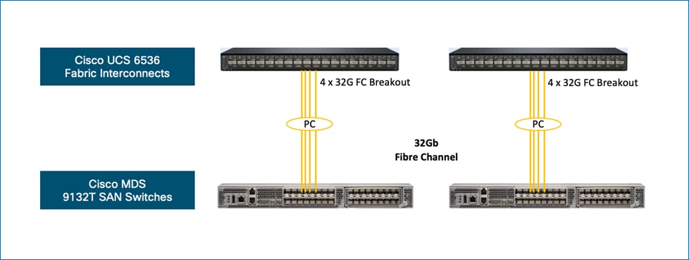
● When using fibre channel, the Cisco UCS 6536 FIs connect to a SAN fabric that the Pure Storage FlashArray also connects to. To connect to the fabric, ports on the UCS 6536 FIs are provisioned as 32G FC channel ports. The SAN fabric in this design are a pair of Cisco MDS 9132T SAN switches but other models of MDS switches can also be used in this design. In larger Enterprises with SAN fabrics that consists of several switches, the MDS switches would connect to the larger fabric to connect to the Pure Storage FlashArray. To enable the connectivity in this design, each Cisco UCS 6536 Fabric Interconnect in N port virtualization (NPV) mode connects to a Cisco MDS 9132T FC switch in N port identifier virtualization (NPIV) mode using 4 x 32G FC links in a port-channel configuration. As bandwidth needs grow, additional links can be added to the port-channel as needed. The SAN fabric is designed to provide two redundant paths (VSAN-A, VSAN-B) through the fabric between Cisco UCS compute and Pure Storage. The port-channel from MDS-A to FI-A path is part of VSAN-A path, and the port-channel from MDS-B to FI-B is part of VSAN-B path.
● When using IP/ethernet, the Cisco UCS 6536 FIs leverages the upstream connections to the Cisco Nexus switches to also connect to the Pure Storage FlashArray. To enable the connectivity for IP/Ethernet based storage access, the design uses multiple 25GbE and 100GbE links to connect Cisco Nexus switches to the Pure Storage FlashArray. A combination of on-board ports and host I/O cards are used on the Pure Storage FlashArray to connect to the Cisco Nexus switches.
Switching Mode
Cisco UCS 6536 Fabric Interconnects are deployed in end-host switching mode (default) which determines how ethernet and fiber channel traffic are forwarded through the Fabric Interconnects.
The ethernet end-host switching mode determines how the fabric interconnect behaves as a switching device between the servers and the upstream LAN network. In this mode, the FIs operate as an end host to the upstream LAN network, representing all the servers (nodes/hosts) connected to it. To achieve this, each server’s Virtual Network Interface Card (vNIC) is pinned to an Ethernet uplink port on the FI. If a server is redundantly connected to FI-A and FI-B, each vNIC will be pinned to an uplink on each FI. The uplink ports will appear as server ports to the network that the FIs connect to.
In end-host switching mode, the FIs do not run spanning tree protocol. Instead, it avoids loops using a combination of Deja-Vu checks and Reverse Path Forwarding (RFP), by denying uplink ports from forwarding traffic to each other and by denying egress server traffic on more than one uplink port at a time. It also limit MAC address learning to ports configured as ‘Server’ or ‘Appliance’ ports.
Note: In end-host mode, if an ethernet uplink port goes down, the vNIC that is hard pinned to that port will also go down as the system cannot re-pin the vNIC to another uplink. To prevent traffic loss, servers should be dual-homed to both Fabric Interconnects.
In this design, four vNICs are used in this design – two for management and two for Application VM traffic.
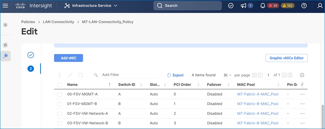
The management vNICs carry the management VLANs (ESXi in-band and infrastructure management) while the VM Network vNICs carry the vMotion VLAN and any VM Network VLANs for the virtual machines deployed on the FlashStack infrastructure.
For IP/ethernet based block and file storage access, the design uses two additional vNICs (04-FSV-StorageData-A, 05-FSV-StorageData-B) that carry traffic for iSCSI, NVMe-TCP, NVMe-RoCEv2 and NFS VLANs used in the design. The storage VLANs are trunked via the Cisco UCS Fabric Interconnects and Nexus switches to enable end-to-end connectivity from ESXi hosts to the datastores hosted on Pure Storage FlashArray.
The fibre channel end-host switching mode determines how the fabric interconnect behaves as a switching device between the servers and the SAN network. In this mode, the FIs operate as an end host to the upstream FC SAN network, representing all the servers connected to it. To achieve this, each server’s Virtual Host Bus Adapter (vHBA) is pinned to a Fibre Channel uplink port on the FI, making the FC ports appear as server or N-ports to the SAN fabric. As such, Fabric Interconnects in end-host mode are operating in N-port Virtualization (NPV) mode. If a server is redundantly connected to FI-A and FI-B using two vHBAs, each vHBA will be pinned to an FC uplink on each FI.
Note: In end-host mode, if a FC uplink port goes down, the vHBA that is hard pinned to that port will also go down as the system cannot re-pin the vHBA to another uplink. To prevent traffic loss, servers should be dual-homed to both Fabric Interconnects.
Cisco UCS Fabric Interconnects provides a flexible unified fabric with the ability to seamlessly support new technologies such as FC-NVMe, in addition to FC-SCSI. In the Cisco UCS service profile for a server, both standard Fibre Channel and FC-NVMe vHBAs can be created to enable access to these datastores from the Cisco UCS/ESXi host. In this design, four vHBAs are enabled in the server’s service profile – two FC initiators and two FC-NVMe initiators through both SAN fabric paths (VSAN-A, VSAN-B). Each vHBA, regardless of type, was automatically assigned a worldwide node name (WWNN) and a worldwide port name (WWPN) to establish FC connectivity to the Pure Storage FlashArray through Cisco MDS switches.
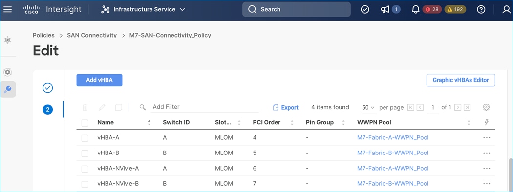
Storage Infrastructure Design
The FlashStack solution supports both fibre channel and IP/ethernet based storage using Pure Storage FlashArray. The storage infrastructure design using either of these options are described in the following sections.
Fibre Channel Storage
For fibre channel, the storage infrastructure in the FlashStack VSI solution consists of a pair of Cisco MDS 9132T switches providing 32G FC SAN connectivity to a Pure Storage FlashArray. For high availability, each MDS switch connects to both controllers on the Pure Storage FlashArray ensuring that there is a VSAN-A and VSAN-B path to both controllers.
The solution supports both Fibre Channel (FC-SCSI) and NVMe over Fiber Channel (FC-NVMe) storage. FC-NVMe is an extension of the NVMe network protocol to Fibre Channel to deliver faster and more efficient connectivity between storage and servers while also reducing the CPU utilization on the hosts.
The solution uses FC-SCSI and FC-NVMe to present block VMFS/VVols Datastores to virtual machines and applications running on the virtual machines. For stateless compute, the solution also uses SAN boot from a FC-SCSI LUN to load ESXi on the Cisco UCS servers. The solution was validated using the following types of volumes:
● FC-SCSI volumes for SAN boot of ESXi servers, one boot volume per server
● FC-NVMe for Datastores/Volumes
To support the above, four vHBAs, two FC-NVMe initiators and two FC initiators are created for each Cisco UCS server, using the server profile. The two initiators for each protocol (FC, FC-NVMe) provide redundant connectivity through each SAN fabric (VSAN-A, VSAN-B). Both Fibre Channel and FC-NVMe vHBAs can exist in a Cisco UCS server profile on a single server.
Cisco Intersight, in IMM Mode, provides a default Fibre Channel adapter policy named fc-nvme-initiator with recommended adapter settings for FC-NVMe. This policy utilizes 16 SCSI I/O queues (the standard VMware Fibre Channel Adapter Policy for FC uses one SCSI I/O queue) to provide a similar optimization of multiple CPU cores servicing multiple queues that can get with the Ethernet Adapter Policies.
To enable access to FC and FC-NVMe volumes on the Pure Storage FlashArray, ports connecting to the MDS switch must be first configured as FC-SCSI and FC-NVMe ports. A given FC port can either be SCSI or NVMe on Pure Storage FlashArray. In this design, two ports on each Pure Storage FlashArray controller are configured as scsi-fc and nvme-fc ports as shown below:
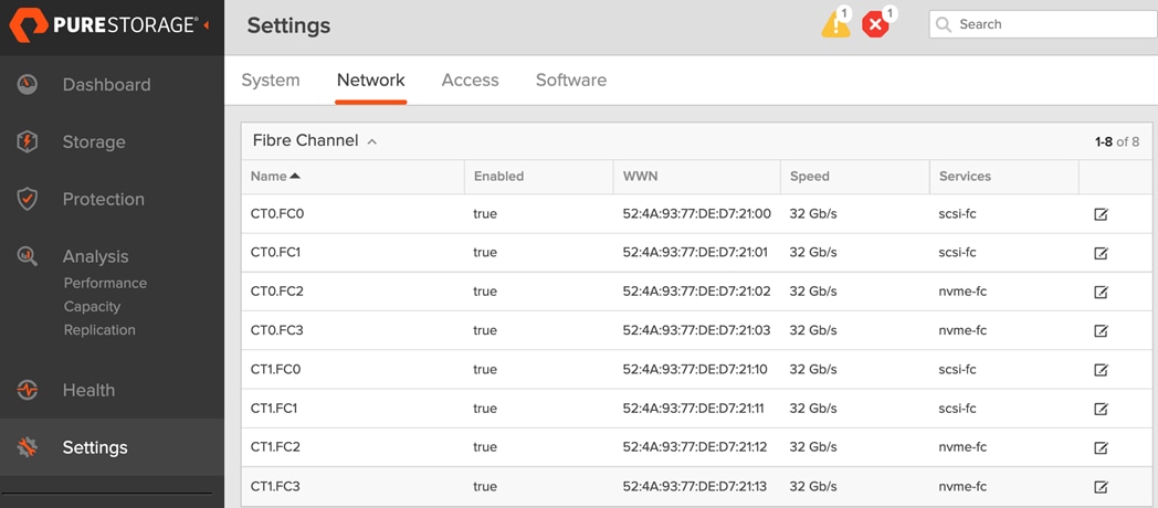
The detailed connectivity for each protocol is shown below: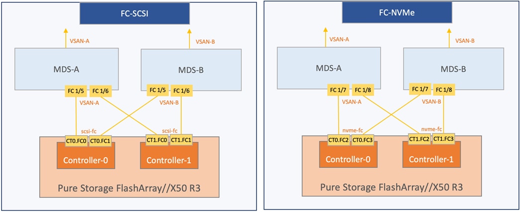
On the Pure Storage FlashArray, host, host groups and FC-SCSI, FC-NVMe volumes must be provisioned before ESXi hosts can access the volumes. It is best practice to map the ESXi Hosts to Host Groups and the Host Groups to Volumes. This ensures the Volume is presented on the same LUN ID to all hosts and allows for simplified management of ESXi Clusters across multiple nodes. Distinct host objects and host groups should be created to separate the volumes being presented to each host object by protocol type, as presenting a volume by more than one protocol is not supported.
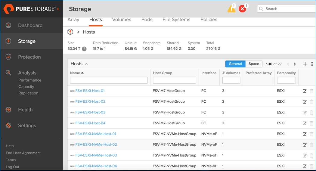
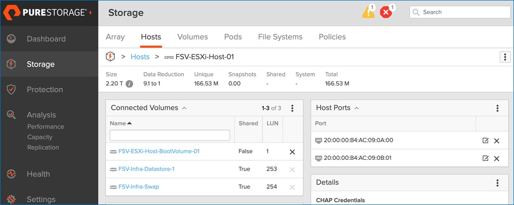
To connect the FC-NVMe and Fibre Channel vHBAs to the corresponding storage targets, Cisco MDS 9132T switches are configured with the appropriate zoning. Single-initiator, multiple-target zones are used for both FC-SCSI and FC-NVMe as shown below:
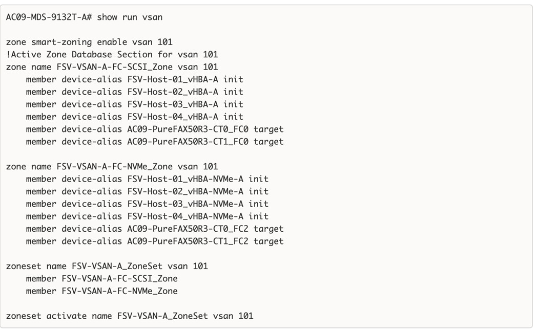
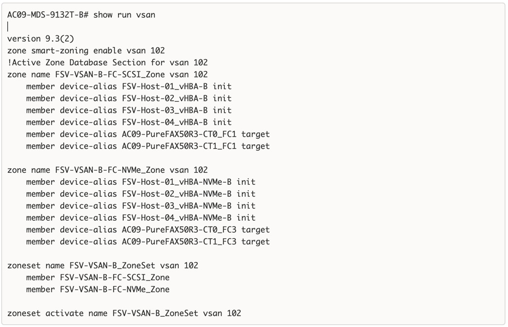
When the SAN zoning and the Pure Storage Flash Array configuration are in place, the ESXi hosts should be able to discover and connect to the FC and FC-NVMe volumes on the Pure Storage FlashArray.
The end-to-end logical connectivity between the FC initiators (Cisco UCS/ESXi host) and targets (Pure Storage FlashArray) are shown in Figure 14.
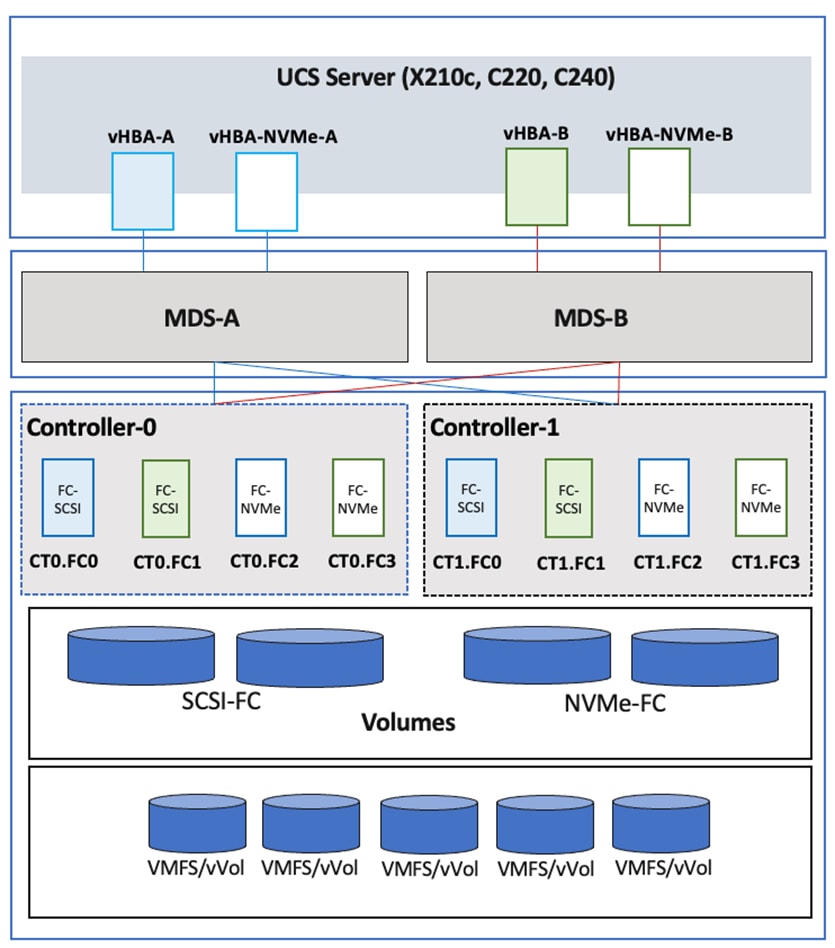
IP/Ethernet Storage
For IP/ethernet storage access, the storage infrastructure in the FlashStack VSI solution leverages a pair of Cisco Nexus 93360YC-FX2 switches to enable 25/100GbE connectivity to a Pure Storage FlashArray. For high availability, each Cisco Nexus switch connects to both controllers on the Pure Storage FlashArray ensuring that there is a VSAN-A and VSAN-B path to both controllers.
The solution supports both block (iSCSI, NVMe-TCP, NVMe-RoCEv2) and file (NFS) ethernet storage. NVMe-TCP and NVMe-RoCEv2 is an extension of the NVMe network protocol to IP/Ethernet to deliver a faster and more efficient connectivity between storage and servers. NVMe over IP/Ethernet has almost all the benefits of FC-NVMe while radically simplifying the networking requirements, including operating over routed networks. The NVMe-TCP targets are connected to the network through a standard TCP infrastructure using Ethernet switches and host-side adapters.
The solution supports using iSCSI, NVMe-TCP, and NVMe-RoCEv2 to present block VMFS/VVols Datastores and NFS to present File Datastores to virtual machines and applications running on the virtual machines. For stateless compute, the solution also uses SAN boot from a iSCSI LUN to load ESXi on the Cisco UCS servers. The solution was validated using the following types of volumes:
● iSCSI for SAN boot of ESXi servers, one boot volume per server
● NFS, NVMe-RoCEv2, NVMe-TCP for Datastores/Volumes
To support the volumes, two vNICs (FSV-StorageData-A, FSV-StorageData-B) are deployed on each server to carry NFS, iSCSi-A/NVMe-TCP-A/NVMe-RoCEv2-A and iSCSi-B/NVMe-TCP-B/NVMe-RoCEv2-B traffic. The MTU on the vNICs are set to use Jumbo MTU (9000). Two iSCSI and four NVMe initiators are created for each UCS server, using the server profile. The two initiators for each protocol (iSCSI, NVMe-TCP, NVMe-RoCEv2) provide redundant connectivity through the IP network to the Pure Storage FlashArray. For NFS, the redundancy relies on the IP/ethernet network, specifically the redundancy and re-routing capabilities of the IP network.
Cisco Intersight, in IMM Mode, provides several ethernet adapter policies that can be used to optimize network traffic into multiple receive queues to enable the use of multiple CPU cores to service the traffic in the queues and achieve a higher network throughput. The adapter policies allow the number of transmit (TX) and RX queues and the queue ring size (buffer size) to be adjusted, and features such as Receive Side Scaling (RSS) to be enabled. RSS allows multiple RX queues to each be assigned to a different CPU core, allowing parallel processing of incoming Ethernet traffic. VMware ESXi 8.0 supports RSS, a single TX queue, and up to 16 RX queues. This CVD utilizes the fifth-generation Cisco VICs which support a ring size up to 16K (16,384), where the previous fourth-generation VICs support a ring size up to 4K (4096). Increasing the ring size can increase the latency, but on higher speed (100GbE) interfaces that this CVD primarily uses, the higher speeds mean less time the data sits in the buffers, thereby minimize the latency impact. In this CVD, up to four Ethernet Adapter policies are defined and can be used as needed.
| Policy Name |
TX Queues |
TX Ring Size |
RX Queues |
RX Ring Size |
RSS |
| VMware-Default |
1 |
256 |
1 |
512 |
Disabled |
| VMware-High Traffic |
1 |
4096 |
8 |
4096 |
Enabled |
| VMware-4G-16RXQs |
1 |
4096 |
16 |
4096 |
Enabled |
| VMware-5G-16RXQs |
1 |
16384 |
16 |
16384 |
Enabled |
Note: In addition to the above parameters, the Completion Queue Count (TX Queues + RX Queues) and Interrupts (Completion Queue Count + 2) have also been modified.
For more information on configuring Ethernet Adapter polices, go to: https://www.cisco.com/c/en/us/products/collateral/interfaces-modules/unified-computing-system-adapters/white-paper-c11-744754.html.
To enable access to iSCSI, NVMe-TCP, NVME-RoCEv2 and NFS volumes on the Pure Storage FlashArray, ports connecting to the Nexus switch must be first configured to reflect the storage protocol being used. A given Ethernet port can be configured as iscsi, nvme-roce, or nvme-tcp on Pure Storage FlashArray. In this design, two ports on each Pure Storage FlashArray controller are configured as iscsi, nvme-tcp and nvme-roce as shown below. For NFS, the iscsi ports are used for both for block and file access.
For each protocol, the Nexus switches in the FlashStack design connect to the two controllers on the Pure Storage FlashArray using a highly redundant design as shown below:
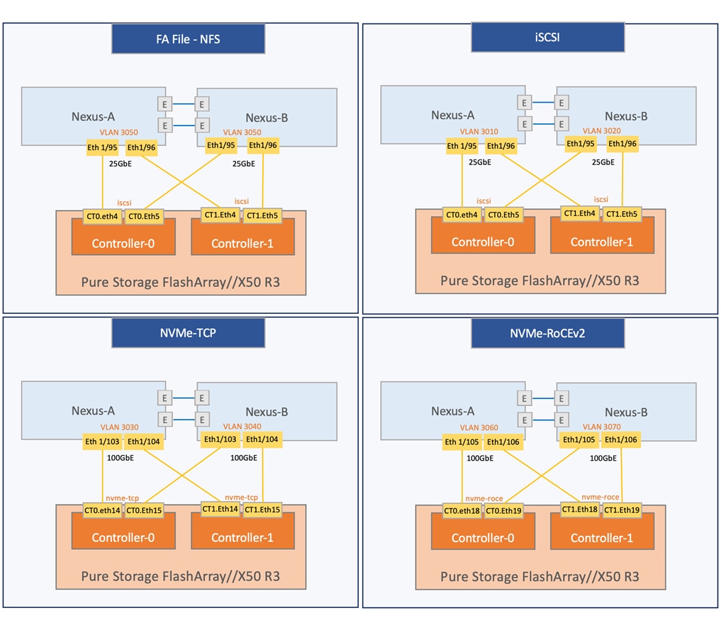
For FA file services (NFS), the physical ports are configured for iscsi service which are then bundled to form a virtual interface(filevif) for use by FA File as shown below:
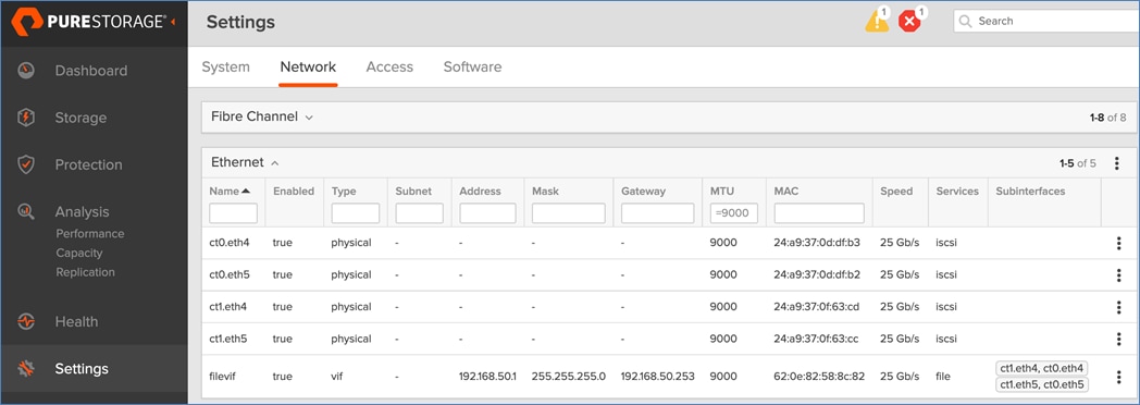
On the Pure Storage FlashArray, similar to provisioning FC storage, host, host groups and NFS, iSCSI and NVMe-TCP/NVMe-RoCEv2 volumes must be provisioned before ESXi hosts can access the volumes. It is best practice to map the ESXi Hosts to Host Groups and the Host Groups to Volumes. Distinct host objects and host groups should be created to separate the volumes being presented to each host object by protocol type, as presenting a volume by more than one protocol is not supported.
The end-to-end logical connectivity between the FC initiators (Cisco UCS/ESXi host) and targets (Pure Storage FlashArray) are shown in Figure 15.
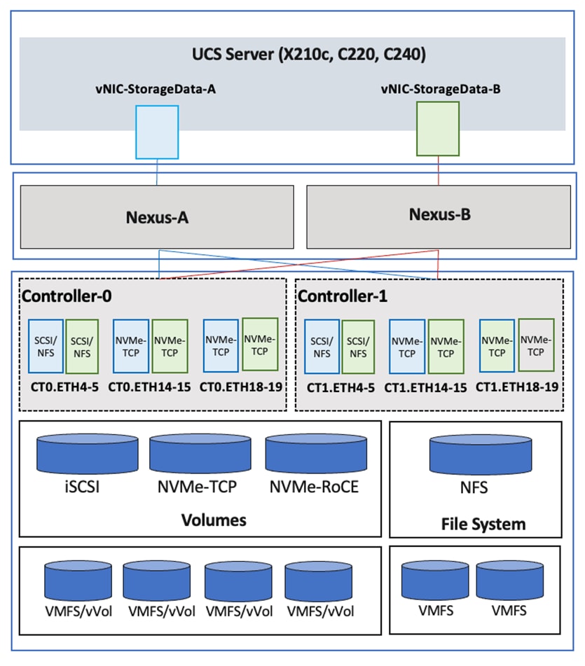
vSphere Plugin
Pure Storage also provides a vSphere plugin and integration with Cisco Intersight through Intersight Assist enabling visibility and management from vCenter and Cisco Intersight.
FA File Services
To consume FA file services for NFS datastores for VMware vSphere, the following components will need to be configured on the Pure Storage FlashArray:
● FA File Services
● Filesystem
● Managed Directory
● Export (created by export policies)
The hierarchy for FA File services, filesystems, managed directories, and exports are as follows:
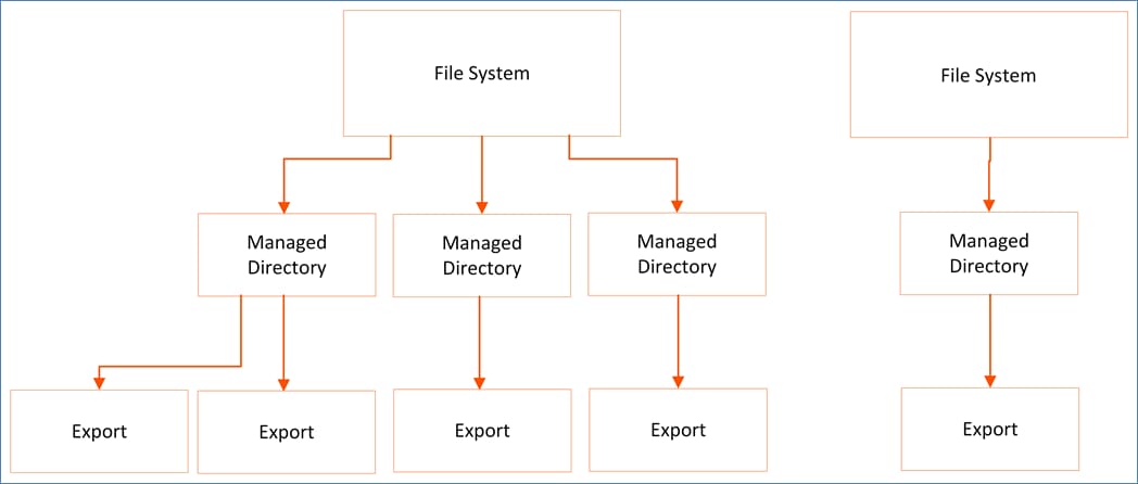
In the above example, you see two file systems, multiple managed directories under those file systems, and exports assigned to the managed directories.
At least 1 file system needs to be created to utilize File Services, but multiple file systems can exist on a Pure Storage FlashArray. Each file system can have multiple managed directories, with each managed directory being mapped to a single file system and being assigned a name and path.
Managed directories are the primary objects for file services and are used in conjunction with policies to create shares/exports, create snapshot schedules, and view performance/space metrics.
To export the managed directories for access by hosts, an SMB or NFS export policy must be attached. This export policy must have a name and must be enabled for the export to be visible from the Pure Storage FlashArray. For NFS export policies, a client filter for read-write access, and root squash must be defined.
To create an export, select a managed directory, an NFS export policy, and enter the name of the export (used to mount this path for clients to access).
The network infrastructure in the FlashStack VSI design consists of a pair of Cisco Nexus 93360YC-FX2 switches that provide connectivity to internal networks and networks outside the Enterprise. To connect to the Cisco UCS Fabric Interconnects, the switches are deployed in a virtual port-channel (vPC) configuration for a highly available design. The virtual port-channel enables links from a given Cisco UCS Fabric Interconnect that connects to the two Cisco Nexus switches to appear as a single port channel from that Fabric Interconnect’s perspective. vPC provides both link and node-level in addition to the following benefits:
● Eliminates Spanning Tree Protocol (STP) blocked ports and uses all available uplink bandwidth
● Allows dual-homed servers to operate in active-active mode
● Provides fast convergence upon link or device failure
vPC also uses native split horizon/loop management provided by port-channeling technology such that a packet entering a port-channel cannot immediately exit that same port-channel.
For higher bandwidth and resiliency, multiple links (4 x 100GbE) are used for uplink connectivity to the Cisco Nexus switches. Cisco UCS FI and Cisco Nexus switches support 802.3ad standards for aggregating links into a port-channel (PC) using Link Aggregation Protocol (LACP). Multiple links from each FI are bundled together in a port-channel and connected to upstream Nexus switches in a VPC configuration. This design provides a higher level of resiliency while also providing higher aggregate bandwidth for LAN, SAN, and Management traffic to/from the Cisco UCS domain. The port-channels operate as trunks, carrying traffic from multiple 802.1Q VLANs to the Nexus fabric.
The Cisco Nexus switches will also have upstream connectivity to an Enterprise’s existing data center for reachability to other networks.
For FA File, the Cisco Nexus switches use 4 x 25GbE ports configured as access ports and using NFS VLAN, to connect to both controllers.
Virtualization Design
The Cisco UCS domain consisting of a pair of Cisco UCS Fabric Interconnects and servers attached to it are provisioned to be a part of a single VMware vSphere cluster for hosting application workloads. A single Cisco UCS domain in Intersight Managed Mode can support up to 20 UCS chassis with 160 servers. Enterprises can configure servers to be part of a single or multiple VMware vSphere clusters. The management components (for example, Intersight Assist) in the solution are hosted on an existing management cluster and is outside the scope of this document.
VMware vSphere 8.0 is deployed on all the for Cisco UCS servers using the Operating System Software Install workflow that provides a simpler, hands-off approach to upgrading ESXi on multiple servers in parallel. For more information, see: https://www.intersight.com/help/saas/resources/operating_system_installation_overview#intersight_managed_mode_installation_requirements
Infrastructure connectivity is critical to the operation of a FlashStack VSI environment. The design requires multiple networks and VLANs/subnets to provide the critical infrastructure connectivity. The infrastructure required connectivity when using fibre channel and IP/Ethernet based storage are outlined in the following sections.
Virtualization Design – when using FC storage
The infrastructure connectivity required for a FlashStack VSI environment using FC storage include:
● In-Band Management: In-band management connectivity is required for reachability to ESXi hosts from VMware vCenter reachable through the Cisco Nexus switches. Each host in the cluster also requires a VMkernel interface. The in-band management VLAN in the table below provides this connectivity.
● Storage: Cisco UCS servers in the FlashStack VSI design use Fibre Channel SAN boot for achieving stateless compute and for overall ease of managing the Operating System (OS) in a large environment with 100s of servers. The ESXi hosts in the solution therefore require storage connectivity to Pure Storage to access its boot volumes. Once the ESXi is installed and the hosts are operational and part of a vSphere cluster, the virtual machine (VM) workloads hosted on the cluster will also require storage access for the VMs and for the workloads running on them. In the FlashStack VSI design, both FC-SCSI and FC-NVMe datastores are supported. Dedicated vHBAs are deployed in this design to provide this connectivity.
● vMotion: To enable vMotion for guest VMs on ESXi hosts in the cluster, a vMotion network is needed for connectivity between ESXi hosts in the cluster. Each host in the cluster also requires a VMkernel interface. The vMotion VLANs listed in Table 3 provide this connectivity.
In addition to the VLANs (and associated IP subnets), additional VLANs will be required for the VM Network traffic. You can add as many as required. A small number of VLANs are used in this design as listed in Table 3 for validation purposes.
Table 3 lists the infrastructure and virtual machine VLANs and networks used in this design.
Table 3. Infrastructure and Virtual Machine VLANs and Networks
| VLAN Type |
VLAN Name |
VLAN ID |
IP Subnet/Mask |
| Native VLAN |
Native_VLAN |
2 |
N/A |
| In-Band Management |
FSV-IB-MGMT_VLAN |
1191 |
10.119.1.0/24 |
| vMotion |
FSV-vMotion_VLAN |
3000 |
192.168.0.0/24 |
| VM Network |
FSV-VM-Network_VLAN |
1193-1199 |
10.119.[2-9].0/24 |
The infrastructure virtual machine VLANs are deployed either on a VMware vSphere virtual switch (vSwitch) or a VMware vSphere distributed virtual switch (vDS). The design separates the different traffic types across multiple VMware virtual switches (vSwitch or vDS).
The design uses two virtual switches and assigns two uplinks each to all hosts. The uplinks on the ESXi host are virtual NICs (vNICs) or virtual interfaces on each server’s Cisco UCS VIC adapter, created by the server profile configuration for that server. VMware port-groups are also associated with the virtual switches to enable endpoints (VMkernel, VMs) to be added. The vNIC and (optional) vHBA distribution for the ESXi hosts is as follows:
● Two vNICs on a VMware vSwitch for in-band management.
● Two vNICs for VMware vDS for vMotion and application VM traffic.
● Four vHBAs for FC stateless boot, FC-SCSI and FC-NVME datastores.
The vNICs created by the Cisco UCS server profile and the corresponding vmnics on each ESXi host are listed in Table 4.
Table 4. Infrastructure and Virtual Machine Virtual Interfaces (Cisco UCS, ESXi)
| vNIC Name |
vNIC Name |
| 00-FSV-MGMT-A |
vmnic0 |
| 01-FSV-MGMT-B |
vmnic1 |
| 02-FSV-VM-NETWORK-A |
vmnic2 |
| 03-FSV- VM-NETWORK-B |
vmnic3 |
The ESXi virtual networking design for each host, including the vNICs and virtual machine NICs (vmnics) and the VMware port-groups are shown in Figure 16.
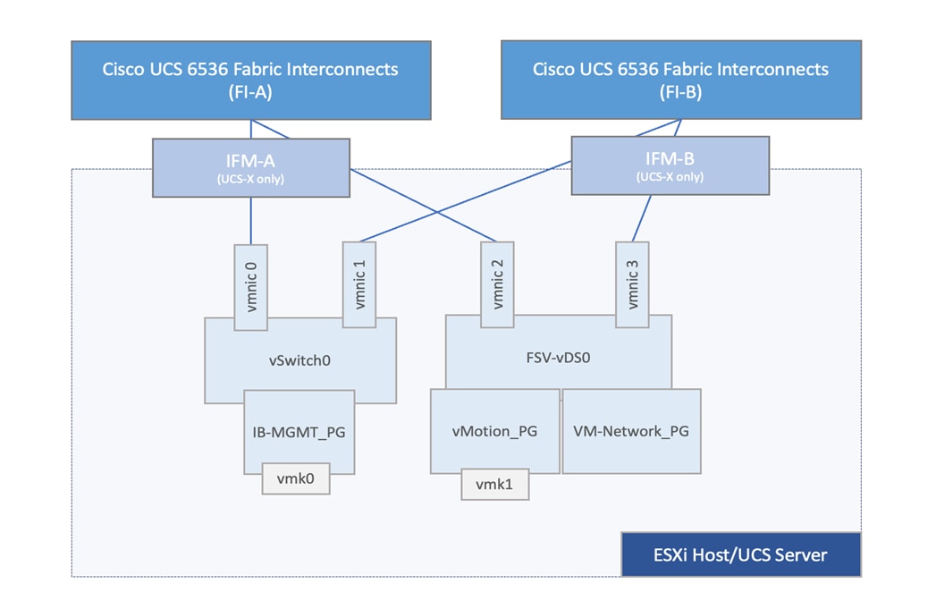
Note: vHBAs are not shown in the topology as it is not part of the ESXi virtual switching configuration.
Virtualization Design – when using IP/Ethernet storage
For IP/Ethernet storage access, the solution uses the following ESXi virtual networking design for each host in Table 5.
Table 5. Infrastructure and Virtual Machine VLANs and Networks – with NFS
| VLAN Type |
VLAN Name |
VLAN ID |
IP Subnet/Mask |
| Native VLAN |
Native_VLAN |
2 |
N/A |
| In-Band Management |
FSV-IB-MGMT_VLAN |
1191 |
10.119.1.0/24 |
| vMotion |
FSV-vMotion_VLAN |
3000 |
192.168.0.0/24 |
| Storage |
FSV-NFS_VLAN |
3050 |
192.168.50.0/24 |
|
|
FSV-iSCSI-A_VLAN |
3010 |
192.168.10.0/24 |
|
|
FSV-iSCSI-B_VLAN |
3020 |
192.168.20.0/24 |
|
|
FSV-NVMe-TCP-A_VLAN |
3030 |
192.168.30.0/24 |
|
|
FSV-NVMe-TCP-A_VLAN |
3040 |
192.168.40.0/24 |
|
|
FSV-NVMe-RoCEv2-A_VLAN |
3060 |
192.168.60.0/24 |
|
|
FSV-NVMe-RoCEv2-A_VLAN |
3070 |
192.168.70.0/24 |
| VM Network |
FSV-VM-Network_VLAN |
1193-1199 |
10.119.[2-9].0/24 |
The ESXi virtual networking design for each host, including the vNICs and virtual machine NICs (vmnics) and the VMware port-groups are shown in Figure 17.
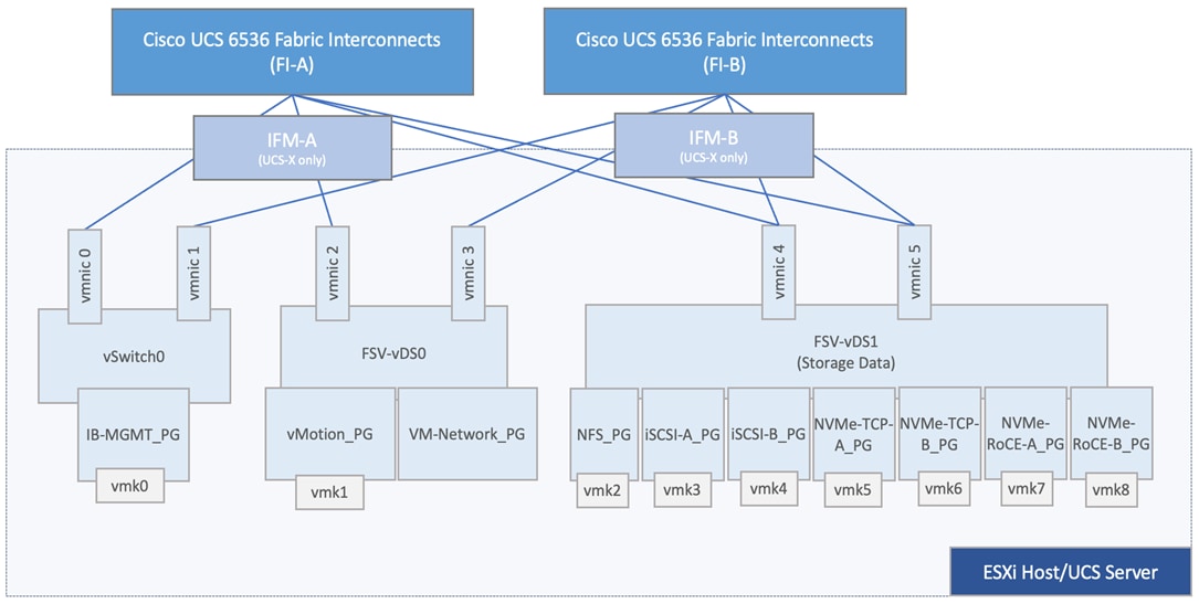
Out-of-band Management Network
The design uses Out-of-Band Management to access the management interfaces of all components in the FlashStack VSI solution. Out-of-Band Management is essential for the initial setup and in the event of a failure where in-band management becomes unavailable. This network is a dedicated, separate network, typically part of larger out-of-band network that the Enterprise already has in place. The design of this network is outside the scope of the design discussed in this document.
Note: This solution also uses in-band management for infrastructure management, including managing ESXi hosts from vCenter. The in-band management networking is discussed in the Sub-System Design > Network Design section of this document.
Cisco Intersight Integration for FlashStack
Cisco Intersight provides additional capability for simplifying IT operations by providing monitoring, optimization, and orchestration capabilities to manage non-Cisco UCS and third-party components in the solution through supported connectors available on the Intersight Assist Appliance. Intersight Assist is deployed in the FlashStack solution, in the in-band management network and is used to manage Pure Storage FlashArray, VMware vCenter, Cisco MDS and Cisco Nexus switches. Cisco Intersight Assist, through the connectors, enables Cisco Intersight to communicate with these devices and gather inventory and other monitoring information.
Note: A single Cisco Intersight Assist virtual appliance supports connectors for multiple devices.
Cisco Intersight integration with FlashStack is leveraged in this solution for the following capabilities:
● Monitor the virtualization of storage and network environment.
● Add various dashboard widgets to obtain useful at-a-glance information.
● Perform common Virtual Machine tasks such as power on/off, remote console and so on.
You can also use the following addition capabilities as needed:
● Use Intersight Workload Optimizer to optimize non- Cisco UCS FlashStack components.
● Use Intersight Cloud Orchestrator to orchestrate storage, network and VM configuration tasks.
Note: Since Cisco Intersight is a SaaS platform, monitoring and orchestration capabilities are continually being added and delivered seamlessly from the cloud. For the most up to date list of capabilities and features, you should use the help and search capabilities in Cisco Intersight.
To implement the integration, the deployment section of this document provides step-by-step procedures. This integration does require a Cisco Intersight Advantage license. Addition licenses will be required if using Intersight Workload Optimizer.
Storage Considerations
This section summarizes some of the storage related design considerations that enterprises should consider in their FlashStack deployment.
VMware Datastores and General Best Practices
● Install and utilize the Pure Storage Remote vSphere Plugin for the vSphere Client whenever possible for ease of operations for storage provisioning and operations within vCenter.
● While the FlashArray supports multiple protocols for a single host (a mixture of FC, iSCSI, and NVMe), ESXi does not support presenting VMFS storage via more than one protocol. Creating a multi-protocol host object should be avoided on the FlashArray when in use with VMware ESXi.
● A FlashArray volume can be connected to either host objects or host groups. If a volume is intended to be shared by the entire cluster, it is recommended to connect the volume to the host group, not the individual hosts.
● Private volumes, like ESXi boot volumes, should not be connected to the host group as they should not be shared. These volumes should be connected to the host object instead.
● Best practice is to match FlashArray hosts groups with vCenter clusters, to not have more or less hosts in the host group as is in the cluster.
● Set FlashArray host objects to have the FlashArray "ESXi" host personality when using Purity 5.1 or later. This change is REQUIRED for all environments using Purity 6.0+.
● Often the VMware vCenter Server is configured to sync time with the ESXi host it resides on. If you do not use this option, make sure the vCenter Server has NTP properly configured and enabled as well.
It is recommended to review the "Quick Reference: Best Practice Settings" guide on the Pure Storage site for the overview of all recommended settings for any version of ESXi: https://support.purestorage.com/Solutions/VMware_Platform_Guide/User_Guides_for_VMware_Solutions/FlashArray_VMFS_RDM_VMware_Best_Practices_User_Guide/Quick_Reference%3A_Best_Practice_Settings
Fibre Channel
● Use all of the Pure Storage FlashArray Fibre Channel ports and use single initiator to multi-target zoning.
● Avoid ISLs if possible. If not possible, watch for frame discards on ISLs.
● Verify all paths are clean; address any CRCs or similar errors.
● Use consistent ports speeds fabric wide, such as do not connect 2Gb to 8Gb.
● Boot from SAN is supported for Fibre Channel (FC-SCSI). This restriction is not a VMware or Pure Storage limitation but rather a HBA firmware limitation.
iSCSI
● For software iSCSI initiators, without additional configuration the default behavior for iSCSI pathing is for ESXi to leverage its routing tables to identify a path to its configured iSCSI targets. To configure predictable and reliable path selection and failover it is necessary to configure iSCSI port binding (iSCSI multipathing).
● Do not route iSCSI, as it introduces complexity in configuration and troubleshooting, introduces potential latency to your network and introduces potential security concerns.
● Use a MTU of 9000 and use all of the FlashArray's interfaces (critical for iSCSI performance).
● Verify all paths are clean; address any CRCs or similar errors.
● Create at least 8 sessions per host (or, again, use all interfaces on Pure Storage).
● Boot from SAN is supported using iSCSI.
NVMe-oF
● VMware does support vVols with NVMe-FC only starting in VMware vSphere 8.0. Pure Storage does not currently support this but is working on support for NVMe-oF with vVols.
● NVMe-oF does not support clustered VMDKs.
● NVMe-FC does not support directly connected ESXi hosts.
● With the initial release of VMware vSphere 7.0, not all VMware vSphere Storage APIs Array Integration (VAAI) features will be available. This isn't a limitation with Pure Storage or VMware but rather the NVMe spec.
● VMware supports NVMe-RDMA, NVMe-FC and NVMe-TCP starting with VMware vSphere 7.0 U3 and later.
● Boot from SAN is not support using any of the NVMe-oF protocols.
FA File
● If using NFS for VMware vSphere datastores, it is recommended to install the FlashArray NFS VAAI (VMware vSphere APIs for Array Integrations) VIB (vSphere Installation Bundle); this will allow the following primitives: full file clone, fast file clone, reserve space, and extended statistics.
● To enable virtual machine (VM) granular management and reporting with FlashArray-backed NFS datastores on VMware vSphere, automatic directory (autodir) policies can be created on a Pure Storage FlashArray.
● FA File requires a virtual interface with a dedicated IP address using 2 Ethernet ports per controller. These can be iSCSI or replication ports, and they will share traffic on these ports (Ports cannot be in use by management services, a bond, or subnet configuration).
● The virtual interface will use the same MTU as physical ports in use by the VIF and all ethernet ports must have the same MTU set.
● File Services does not support connecting to both MS AD and LDAP at the same time.
● Polices for exports/shares/snapshots can only be attached to managed directories at the file system root or 1 level deep. Space and performance metrics can be seen at all levels of managed directories.
● The option for root squash can only be set once per policy and any additional rules on the same policy must match the first rule.
VMware Virtual Volumes
The FlashStack solution supports VMware Virtual Volumes (vVols) that provides a more granular control of your shared storage environment. VMware vVols is a storage technology that provides policy-based, granular storage configuration for VM storage. When a VM is created, the administrator selects a VM storage policy to associate with it. On the back-end storage array, the storage is provisioned for the VM on a per-VM basis (with 1 config vVol per VM, 1 data vVol per disk) without the VMware administrator being aware of the array specific configuration. Instead, VMware administrators provision storage using native VMware interfaces. Through API-based interaction with an underlying array, VMware administrators can maintain storage configuration compliance using only native VMware interfaces. The Pure Storage FlashArray Plugin for the vSphere Web Client provides the APIs necessary to create, manage, and use vVols from VMware vCenter.
To use vVols with the Pure Storage FlashArray, the Pure Storage FlashArray must be registered as a Protocol Endpoint (PE) in VMware vCenter. The Protocol Endpoint (PE) is also associated with the host group to create the vVol datastore associated with the VM.
The VMware vSphere APIs for Storage Awareness (VASA) is a VMware interface for out-of-band communication between VMware ESXi, vCenter and storage arrays. The arrays’ VASA providers are instances of the VASA service which are registered with the vCenter Server. Pure Storage hosts the VASA provider as redundant instances of the VASA service running on each controller; there is no separate installation or configuration. VASA allows for advanced management functionality and reporting at both VMs and per-disk level of granularity.
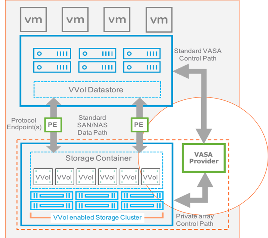
Some of the benefits of VMware vVols are:
● Virtual Disk Granularity: Each virtual disk is a separate volume on the array with is own unique properties.
● Automatic Provisioning: When a VMware administrator requests a new virtual disk for a VM, VMware automatically directs the array to create a volume and present it to the VM. Similarly, when a VMware administrator resizes or deletes a virtual disk, VMware directs the array to resize or remove the volume.
● Array-level VM Visibility: Because arrays recognize both VMs and their virtual disks, they can manage and report on performance and space utilization with both VM and individual virtual disk granularity.
● Storage Policy Based Management: With visibility to individual virtual disks, arrays can take snapshots and replicate volumes at the precise granularity required. VMware can discover an array’s virtual disks and allow VMware administrators to manage each vVol’s capabilities either ad hoc or by specifying policies. If a storage administrator overrides a vVol capability configured by a VMware administrator, the VMware administrator is alerted to the non-compliance.
Virtual Volume Best Practices and Other Considerations
● A VM's Config vVol stores the files required to build and manage the VM. Ensure that the Config vVol is part of an existing Pure Storage FlashArray Protection Group. Alternately, if you are using storage policy that include snapshot or if you prefer manual snapshots, Config vVol should be part of these snapshots. This will help with the VM recovery process if the VM is deleted.
● Create a local array admin user to register the storage provider instead of using the local “pureuser” account.
● vCenter Server should not reside on vVols.
● ESXi Hosts, vCenter Server and FlashArray should synchronize time to the same NTP Server.
● Use the Pure Storage Plugin for the vSphere Client to register the Pure Storage FlashArray storage provider and mount the vVols datastore.
● A single PE utilizing the default device queue depth is sufficient in the design.
● VMDK resizing of VMs that resides on a vVol should be completed from vSphere Client and not from FlashArray GUI.
● TCP port 8084 must be open and accessible from vCenter Servers and ESXi hosts to the FlashArray that will be used for vVol.
For more information on vVols best practices, refer to the following summary: https://support.purestorage.com/Solutions/VMware_Platform_Guide/User_Guides_for_VMware_Solutions/Virtual_Volumes_User_Guide/vVols_User_Guide%3A_Best_Practice_Summary.
Sustainability
Data centers around the world currently account for approximately 1% of the global electricity consumption and 2% of the total within US, making them significant contributors to energy consumption. Among the various components within a data center, servers consume the largest share of the electricity. According to Gartner, the proportion of the overall data center power budget allocated to storage is expected to double by 2030, rising from less than 20% in 2020 to nearly 40%.
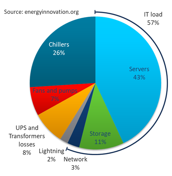
The compute and storage power consumption reflects the growing demand for servers and storage systems within data centers. As new applications and data continues to proliferate, the demand for the compute and storage capacity and performance is expected to rise. As environmental, social, and governance (ESG) issues become a corporate priority at all levels of organizations across the globe, so will the demand for efficient power consumption and sustainable energy across products and processes.
Organizations are actively seeking diverse strategies to minimize power consumption and achieve the sustainability targets that they have established for themselves. There are several approaches that can be taken to minimize power consumption and meet sustainability goals, some of which are outlined below.
Sustainable Design
One key approach is to focus on a modern, sustainable design while continuing efforts to reduce technical debt, and increase overall efficiency. Data center consolidation, modernization and maximizing rack utilization are crucial steps to achieve this goal.
Replacing older servers with advanced models like the Cisco UCS M7 servers introduced in this solution can significantly improve performance and achieve higher virtual machine (VM) consolidation ratios compared to previous generations, while continuing to provide more flexibility and increased performance to support new and evolving applications. The Cisco UCS M7 servers can handle more workloads with a 4-to-1 consolidation ratio compared to previous generation servers.
The Cisco UCS X-9508 used in this solution, provides a future-ready platform with the density and efficiency of blade servers and the expandability and flexibility of rack servers. The modular, chassis-based design allows you to share resources (chassis enclosure, switching fabric, power, cooling) among multiple servers for a more efficient utilization of rack space, power, and cooling, while maintaining the flexibility to expand capabilities as needed. The Cisco UCS-X9508 7-RU chassis supports up to 8 compute nodes with unified connectivity and management. Each compute node can also support up to 6 Solid-State Drives (SSDs), or Non-Volatile Memory Express (NVMe) drives for a total of ~90TB of local storage using 15.3TB NVMe drives available today. For AI/ML, VDI and other compute-intensive workloads, you can add Nvidia and Intel Flex GPUs to the Cisco UCS X-Series chassis, directly on each compute node or using a dedicated PCIe (X440p) node. Cisco UCS-X9508 can support up to 16 GPUs using the X440p PCIe nodes, with the option to add an additional two GPUs on the compute nodes. Cisco UCS X-Series is also designed for the next decade of computing, with the ability to support new technologies as they evolve and mature such as PCI Gen5.0, CXL and liquid cooling for a more efficient data center.
FlashStack reduces data center energy consumption at levels our competitors with legacy solutions cannot. Pure Storage achieves this through higher storage and compute density, always-on data reduction, new Energy- and thermal-efficient designs, along with modular components and the Evergreen model. All of these factors allow for lowered physical and carbon footprint, plus reduction of e-waste, while providing the most performant and energy conscious solution for your data center footprint.
Pure Storage has an ethos of delivering performance and simplicity that allows you to consolidate your IT environments, reduce your overall footprint, and drive higher utilization and reuse.
Sustainable Hardware
The Pure Storage FlashArray and Cisco UCS X-Series platform used in this solution are designed with sustainability in mind. This is a critical factor for enterprises as they modernize their data centers and select infrastructure to consolidate their workloads on.
Cisco UCS X-Series platform is designed with several energy efficient features to optimize power and cooling as outlined below. Cisco UCS X-Series was recently awarded the 2023 SEAL Sustainable Product Award for products that are “purpose-built” for a sustainable future.
● Cisco UCS X-Series chassis uses a more open design for less air impedance and minimal air-handling material to reduce the overall resources that need to be sourced and installed within the system.
● It is equipped with modular, titanium-rated power supply units (PSUs) and 54-volt DC-power delivery system that minimizes the many internal power conversions, internal copper cabling needed, and amperage – saving in both overhead and power loss.
● The Cisco UCS X-Series has modular counter-rotating fans with wider apertures and high cubic feet per minute (CFM). It also has innovative zone-based cooling to optimize only those components needing more handling. And with an innovative fan speed algorithm, an industry first, the Cisco UCS X-Series can optimize power consumption and minimize hysteresis to prevent fan speed overshot and reduce overall fan power consumption.
● The architecture of the Cisco UCS X-Series can extend the useful life of server elements using a midplane-less design to disaggregate components, with the ability to support new high-speed interconnects in the future and extend the refresh cycle of components. For example, the Cisco UCS X-Series will be able to support technologies such as Compute Express Link (CXL) for interconnecting elements within a node.
The core technologies of Pure Storage integrate software and hardware architecture to deliver not just unmatched density, longevity, and efficiency, but to continually improve and drive further efficiencies over time. We believe that only through tightly integrated software and hardware can these benefits be created.
Pure Storage’s unique Evergreen architecture means that our products do not become obsolete or require wholesale replacement like traditional systems. The architecture allows our arrays to be upgraded non-disruptively, allowing you to continuously benefit from the latest hardware and software technology, reducing unnecessary product replacements and associated e-waste.
Optimized Operations and Energy Management
To meet sustainability targets, Enterprises must first evaluate where they are at before they can work towards reducing it through consolidation, optimization, modernization, and other efficiency measures. Monitoring energy consumption is therefore the initial step towards reducing it. Using Cisco Intersight makes it easier to achieve sustainability targets by providing Enterprise-wide and global visibility. Intersight can simplify energy management by providing centralized management, with the ability to implement optimization policies at scale and with ease.
The FlashStack VSI solution offers several monitoring and optimization capabilities, at various layers of the stack, to help enterprises achieve their sustainability objectives. Enterprises can implement these capabilities to make progress towards their sustainability goals.
For Cisco UCS X-Series servers, server power usage is shown under the server’s Statistics tab for various customizable intervals as shown below. By enabling Intelligent Platform Management Interface (IPMI) over LAN policy on each server, power usage and other metrics can be queried via IPMI over LAN, allowing multiple management components (for example, VMware vCenter, Cisco Intersight) to monitor and provide a broader picture of the power consumption over time from a server and workload perspective. Alternatively, you can also use Redfish is to query server power usage when managing the servers in Intersight Managed Mode.
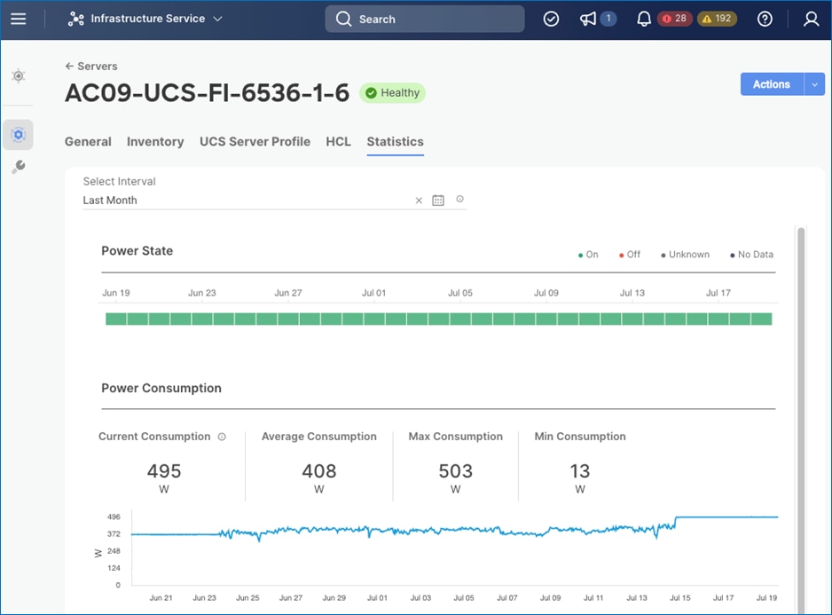
To reduce power consumption, Cisco Intersight provides Server BIOS policies that can be configured in this solution to provide power conservation potentially without affecting performance. These settings can be disabled if maximum performance is required. Cisco Intersight IMM provides power policies at both the Cisco UCS X-Series chassis and server level, which allows you to adjust the balance of power consumption and performance to meet application needs. These policies provide multiple options specifying both how Cisco UCS X-Series Chassis fans are controlled and how Cisco UCS X-Series Chassis power supplies are utilized. These policies also provide priority levels for Cisco UCS X-Series servers for power allocation to these servers.
The server policies available on the Cisco UCS X-Series M7 servers in this solution are:
Note: For more information on the BIOS policy options below, see Performance Tuning Best Practices Guide for Cisco UCS M7 Platforms.
● BIOS Policy > Processor > Energy Efficient Turbo
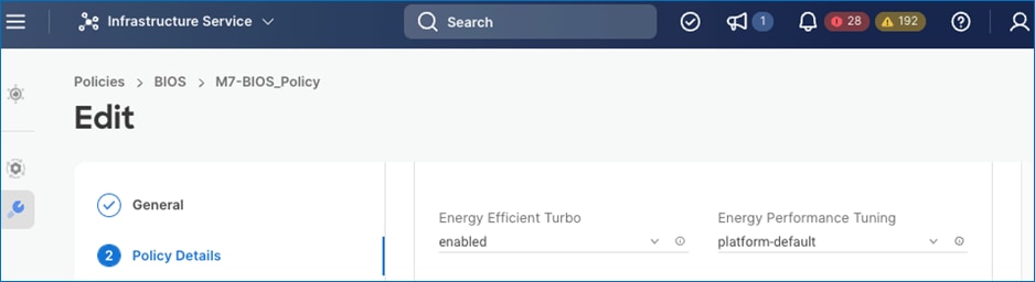
● BIOS Policy > Processor > (Package C State Limit, Processor C1E, Processor C6 Report)
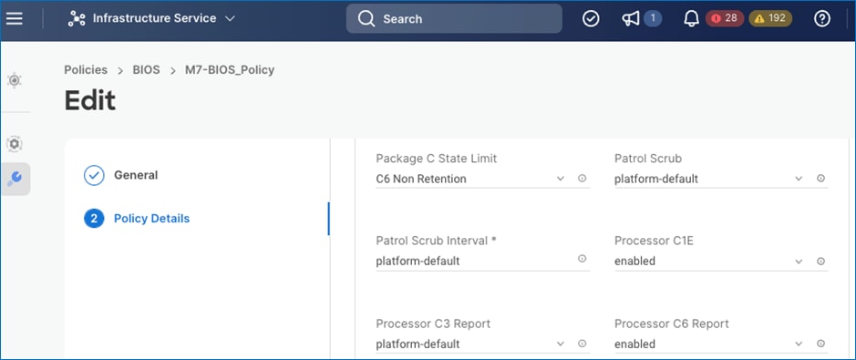
● BIOS Policy > Processor > Workload Configuration
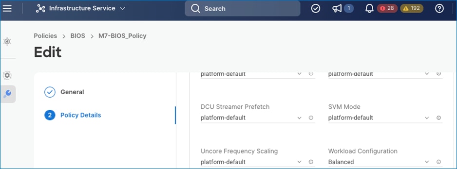
The chassis policies available on the Cisco UCS X-Series in this solution are:
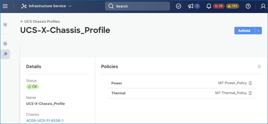
● Power Policies – For Cisco UCS X-series Chassis Only
◦ Power Save Mode: If the requested power budget is less than available power capacity, the additional PSUs not required to comply with redundancy policy are placed in Power Save mode.
◦ Dynamic Power Rebalancing: If enabled, this mode allows the chassis to dynamically reallocate the power between servers depending on their power usage.
◦ Extended Power Capacity: If Enabled, this mode allows chassis available power to be increased by borrowing power from redundant power supplies.
◦ Power Allocation (Watts): Sets the Allocated Power Budget of the Chassis. This field is only supported for Cisco UCS X-Series Chassis.
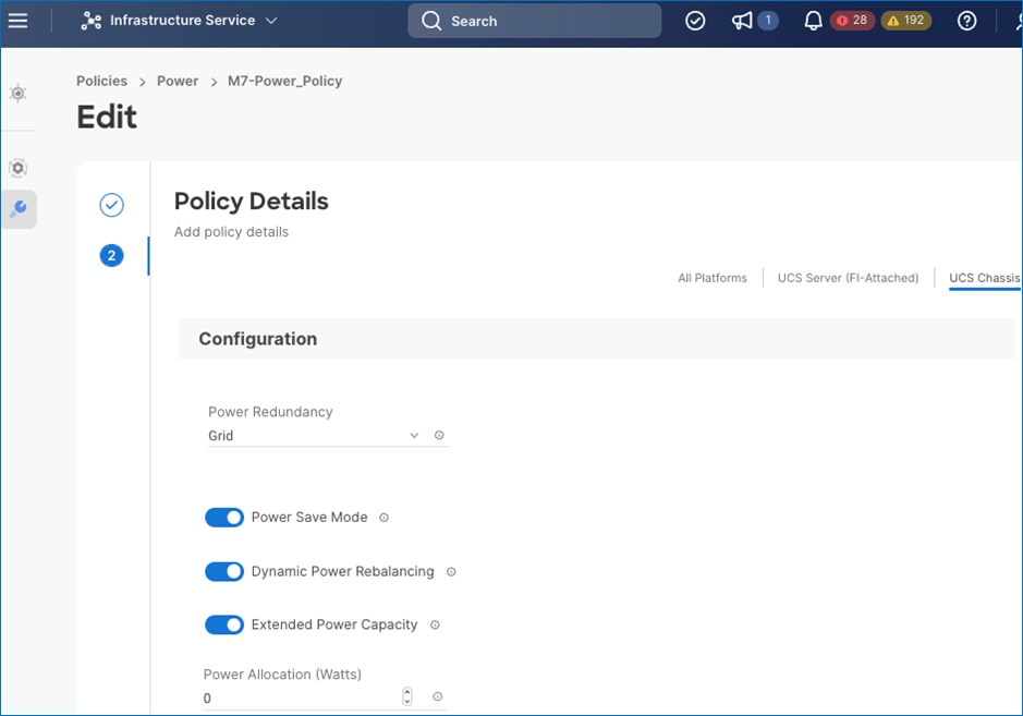
● Additional Power Policies – For Cisco UCS X-Series and Cisco UCS B-Series Chassis
◦ Power Profiling > Power Priority: This priority is used to determine the initial power allocation for servers.
◦ Power Profiling > Power Restore: In the absence of Intersight connectivity, the chassis will use this policy to recover the host power after a power loss event.
◦ Power Profiling > Power Redundancy: Redundancy Mode determines the number of PSUs the chassis keeps as redundant. N+2 mode is only supported on Cisco UCS X-Series.
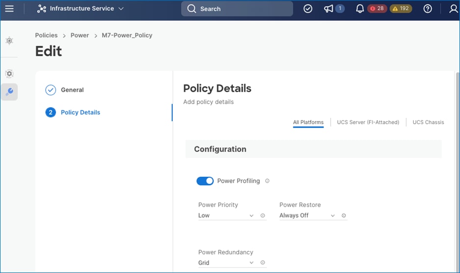
In addition to the power consumption monitoring and policies, Cisco Intersight also offers Intersight Workload Optimizer (IWO) as an add-on service that can analyze and optimize resources in the FlashStack VSI solution. IWO uses an always-on analysis engine with machine intelligence to provide specific, actionable recommendations to manage and optimize resources. By implementing the recommendations that IWO provides, you can right-size your environment and significantly reduce sub-optimal use of resources in your data center. The unused resources from consolidation can then be put on-standby until it is needed to reduce power consumption in the data center.
Note: When implementing IWO recommendations with power management policies from VMware vSphere (see below), it is important that the two components do not step on each other’s actions. In this scenario, enterprises should evaluate IWO recommendations but not implement them if there is a concern that the two would interfere with each other. At a minimum, implement changes manually rather than automated response to IWO recommendations.
VMware vSphere used in the FlashStack VSI solution also provides several energy management capabilities as described below.
For more details, see Performance Best Practices for VMware vSphere 8.0.
● Host Power Management (HPM) – When a host is powered on, this feature can reduce the power consumption of the host. This is enable using the Power Policy Option that can be set to High Performance, Balanced, Low Power, or Custom. In this CVD, the policy is set to Balanced (default) for a balance between power consumption and performance. Enterprises can change this policy as needed to meet the needs of their workloads and environment. In VMware vSphere 8.0, this policy can be changed by navigating to [vSphere Cluster Name] > Host > Configure > Hardware.
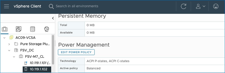
Note: The technology field shows a list of the technologies available to ESXi on that host. For power savings, both ACPI P-states and ACPI C-states should be available to ESXi.
● Distributed Power Management (DPM) – Unlike HPM, DPM reduces power consumption by powering-off under-utilized ESXi hosts in a cluster. DPM will first migrate virtual machines to other hosts in the cluster before putting the hosts on stand-by. When demand increases, DPM will bring the hosts back online and load-balance workloads across all hosts in the cluster. DPM uses Distributed Resource Scheduling (DRS) to migrate VM workloads and is therefore configured along with DRS (at the cluster-level) as shown below.
Note: DPM will not violate VMware High Availability (HA) settings and takes it into account to meet the HA requirements.
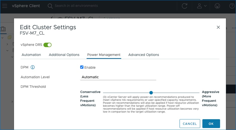
● DPM requires IPMI configuration on the Cisco UCS server which was deployed using the IPMI over LAN policy in the Cisco UCS Server Profile configuration as discussed earlier. IPMI settings must also be configured in VMware VCenter by navigating to [vSphere Cluster Name] > Host > Configure > System > Power Management as shown below:
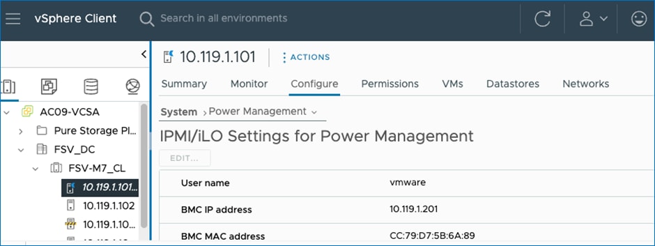
Note: DPM currently does not work with Cisco UCS C-Series servers in Intersight Managed Mode.
● Power Management BIOS Settings: To allow ESXi to implement power management policies, VMware recommends specific BIOS policies be implemented on the server. See the link provided above and the BIOS policies in the Cisco UCS server profile for the policies deployed in this solution.
VMware vSphere 8.0 (and 8.0U1) introduces new monitoring capabilities in the form of new power consumption or “green” metrics at both the host and VM (8.0U1) level. These metrics enable VMware vSphere administrators to monitor the energy consumption of their VMware vSphere environment. The new metrics in VMware vSphere 8.0 are:
● power.capacity.usageSystem: Power consumption from a host’s system-level activities, not attributed to VMs.
● power.capacity.usageSystem: Power consumption of a host’s idle activity when it's not doing anything except being powered-on.
● power.capacity.usageVm: Power consumption of a host due to VM workloads.
These metrics can be enabled and viewed by navigating to [vSphere Cluster Name] > Host > Monitor > Performance > Advanced.
Note: These metrics currently does not yield any data from the Cisco UCS servers in the solution and is currently being investigated.
VMware vCenter Hardware Support Manager (HSM) Integration with Cisco Intersight
The Cisco Hardware Support Manager (HSM) service option enabled with vSphere Lifecycle Manager (vLCM) plug-in allows you to update the Operating System and perform firmware upgrades simultaneously with a single firmware image. You can enable HSM while claiming the VMware vCenter target in Cisco Intersight. You then configure a VMware ESXi cluster in vLCM to be managed with a single image. When composing the image, you select the ESXi Version – can range from the Cisco Custom ISO version to the latest version within the update release, the Vendor Addon downloaded from VMware.com – the additional drivers put into the Cisco Custom ISO, the Firmware and Drivers Addon – the server firmware version pulled from Cisco Intersight, and any additional components – VMware drivers updated since the release of the Cisco Custom ISO. Figure 20 shows an image setup for a cluster with Cisco UCS X210C M7 servers with the latest version of ESXi 8.0 at the time this document was written, the Cisco UCS Addon for VMware ESXi 8.0, Cisco UCS server firmware release 5.1(1.230052) and 3 additional components (2 disk controller drivers and the update UCS Tool component). The Image Compliance section shows that all servers in the cluster are running image compliant software and firmware.
To update any of the image components, you simply edit the image and select the updated component. This could be the ESXi version if a new version has been released or a new version of the server firmware. Once the updated image is saved, the Image Compliance will be check. If any servers are then out of compliance, they can be Remediated. The Remediation process will update the servers one at a time by putting them into Maintenance Mode and then proceeding with the update. If the update is a Cisco UCS firmware update, vCenter will signal the update with Cisco Intersight via the Intersight Assist VM, and Intersight will complete the server firmware update. The image can also be exported to either a JSON file to be imported as the image for another VMware ESXi cluster, as an ISO for installing directly onto ESXi hosts, or as a depot to be loaded into vCenter Image Builder.
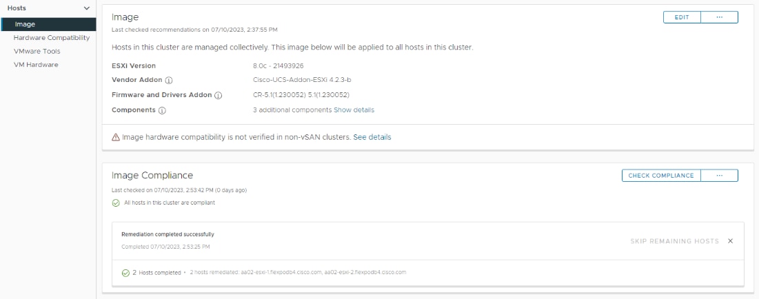
Solution Validation
This chapter contains the following:
● Hardware and Software Matrix
Table 6 lists the hardware components and associated software versions used to validate the solution in Cisco labs. The software versions used are based on compatibility lists provided below from Cisco, Pure Storage, and VMware.
Note: If you’re using other models of hardware and software in your deployments, you should verify interoperability and support using the specific vendor’s compatibility list.
● Pure Storage: https://support.purestorage.com/FlashArray/Getting_Started/Compatibility_Matrix
● Cisco UCS: http://www.cisco.com/web/techdoc/ucs/interoperability/matrix/matrix.html
● VMware: http://www.vmware.com/resources/compatibility/search.php
● FlashStack: https://support.purestorage.com/FlashStack/Product_Information/FlashStack_Compatibility_Matrix
Table 6. Hardware/Software Matrix
| Component |
Software |
Count |
Notes |
| Compute Infrastructure |
|||
| Cisco UCS 6536 Fabric Interconnects (UCS-FI-6536) |
4.2(3c) |
2 |
|
| Cisco UCS X9508 Chassis (UCSX-9508) |
N/A |
1 |
|
| Cisco UCS X9108-100G IFM (UCSX-I-9108-100G) |
|
2 |
|
| Cisco UCS X210c M7 Compute Nodes (UCSX-210C-M7) |
5.3(1.230031) |
2 |
|
| Cisco VIC 15231 MLOM (UCSX-ML-V5D200G) |
|
1 |
2x100G mLOM |
| Cisco VIC – ESXi FNIC driver |
5.0.0.37 |
|
|
| Cisco VIC – ESXi ENIC driver |
1.0.45 |
|
|
| Cisco UCS C220 M7 Rack Server (UCSC-C220-M7S) |
4.3(1.230138) |
1 |
|
| Cisco VIC15428 (Quad Port 10/25/50G mLOM) |
|
1 |
Quad port 10/25/50G mLOM |
| Cisco UCS C240 M7 Rack Server (UCSC-C240-M7SX) |
4.3(1.230138) |
1 |
|
| Cisco VIC 15238 (UCSC-M-V5D200G) |
|
1 |
Dual port 40/100/200G mLOM |
| Storage Infrastructure |
|||
| Pure Storage FlashArray//X50 R3 |
Purity 6.4.5 |
1 |
|
| Pure Storage Plug-in for VMware |
5.3.1 |
|
|
| Pure Storage FlashArray NFS VAAI VIB |
1.0.0-1 |
|
VMware vSphere Storage APIs Array Integration (VAAI) vSphere Installation Bundle (VIB) |
| Network Infrastructure |
|||
| Cisco Nexus 93360YC-FX2 |
10.2(5) |
|
|
| Cisco MDS 9132T |
9.3(2) |
|
|
| Virtualization |
|||
| VMware vCenter |
8.0 |
|
8.0.0.10300 (Build: 21457384) |
| VMware ESXi |
8.0 |
|
Custom ISO (Build: 20513097) |
| Management Components |
|||
| Cisco Intersight |
N/A |
|
|
| Cisco Intersight Assist |
1.0.9-589 |
|
Deployed OVA for 1.0.9-588; Auto updated to the version shown |
The FlashStack solution is a validated approach for deploying Cisco and Pure Storage technologies in an enterprise data center. This release of the FlashStack VSI solution brings the following capabilities:
● FA Unified Block and File consisting of FC-SCSI, FC-NVMe, iSCSI, NVMe-TCP, NVMe-RoCEv2 as well as NFS storage from Pure Storage.
● VMware vSphere 8.0 innovations.
● Fourth generation Intel Xeon Scalable processors with Cisco UCS X210 M7, C220 M7 and C240 M7 servers, enabling up to 60 cores per processor and 8TB of DDR-4800 DIMMs.
● Sustainability monitoring and optimizations to meet Enterprise ESG targets that include power usage monitoring features across all layers of the stack and utilizing the Cisco UCS X-Series advanced power and cooling policies.
Cisco Intersight continues to deliver features that simplify enterprise IT operations, with services and workflows that provide complete visibility and operations across all elements of FlashStack datacenter. Also, Cisco Intersight integration with VMware vCenter and Pure Storage FlashArray extends these capabilities and enable workload optimization to all layers of the FlashStack infrastructure.
Archana Sharma, Technical Leader, Cisco UCS Data Center Solutions, Cisco Systems Inc.
Archana Sharma is a Technical Marketing Engineer with over 20 years of experience at Cisco on a variety of technologies that span Data Center, Desktop Virtualization, Collaboration, and other Layer2 and Layer3 technologies. Archana is focused on systems and solutions for Enterprise and Provider deployments, including delivery of Cisco Validated designs for over 10 years. Archana is currently working on designing and integrating Cisco UCS-based Converged Infrastructure solutions. Archana holds a CCIE (#3080) in routing and switching and a bachelor’s degree in electrical engineering from North Carolina State University.
Joe Houghes, Senior Solutions Architect, Pure Storage, Inc.
Joe Houghes is a Senior Solutions Architect in the Portfolio Solutions team within Pure Storage, focused on solutions on the FlashStack platform along with automation and integration. Joe has experience from over 20 years in Information Technology across various customer and vendor organizations with architecture and operations expertise covering compute, networking, storage, virtualization, business continuity and disaster recovery, and cloud computing technologies, plus automation and integration across many applications and vendor platforms.
Acknowledgements
For their support and contribution to the design, validation, and creation of this Cisco Validated Design, the authors would like to thank:
● John George, Technical Marketing Engineer, Cisco Systems, Inc.
● Rohit Mittal, Product Manager, Cisco Systems, Inc.
● Chris O'Brien, Director, UCS Solutions, Cisco Systems, Inc.
● Craig Waters, Technical Director, Pure Storage, Inc.
This appendix contains the following:
● Appendix A - References used in this guide
● Appendix B - Recommended for you
Appendix A – References used in this guide
GitHub repository for Cisco UCS solutions: https://github.com/ucs-compute-solutions/
Cisco Intersight: https://www.intersight.com
Cisco Intersight Managed Mode: https://www.cisco.com/c/en/us/td/docs/unified_computing/Intersight/b_Intersight_Managed_Mode_Configuration_Guide.html
Cisco Unified Computing System: http://www.cisco.com/en/US/products/ps10265/index.html
Cisco UCS 6536 Fabric Interconnects: https://www.cisco.com/c/en/us/products/collateral/servers-unified-computing/ucs6536-fabric-interconnect-ds.html
Cisco Nexus 9000 Series Switches: http://www.cisco.com/c/en/us/products/switches/nexus-9000-series-switches/index.html
Cisco MDS 9132T Switches: https://www.cisco.com/c/en/us/products/collateral/storage-networking/mds-9100-series-multilayer-fabric-switches/datasheet-c78-739613.html
Pure Storage FlashArray//X: https://www.purestorage.com/products/nvme/flasharray-x.html
Pure Storage FlashArray Compatibility Matrix: https://support.purestorage.com/FlashArray/Getting_Started_with_FlashArray/FlashArray_Compatibility_Matrix
FlashStack Compatibility Matrix: https://support.purestorage.com/FlashStack/Product_Information/FlashStack_Compatibility_Matrix
VMware vCenter Server: http://www.vmware.com/products/vcenter-server/overview.html
VMware vSphere: https://www.vmware.com/products/vsphere
Cisco UCS Hardware Compatibility Matrix: https://ucshcltool.cloudapps.cisco.com/public/
VMware and Cisco Unified Computing System: http://www.vmware.com/resources/compatibility
Pure Storage Interoperability Matrix (requires a support account): https://support.purestorage.com/FlashArray/Getting_Started/Compatibility_Matrix
Pure Storage FlashStack Compatibility Matrix (requires a support account): https://support.purestorage.com/FlashStack/Product_Information/FlashStack_Compatibility_Matrix
Appendix B – Recommended for you
Cisco Enterprise Networks Validated Design and Deployment Guide: https://cs.co/en-cvds
Cisco SD-Access Resource - Cisco Community: https://cs.co/sda-resources
Cisco SD-Access Segmentation Design Guide: https://cs.co/sda-segment-sdg
For comments and suggestions about this guide and related guides, join the discussion on Cisco Community at https://cs.co/en-cvds.
CVD Program
ALL DESIGNS, SPECIFICATIONS, STATEMENTS, INFORMATION, AND RECOMMENDATIONS (COLLECTIVELY, "DESIGNS") IN THIS MANUAL ARE PRESENTED "AS IS," WITH ALL FAULTS. CISCO AND ITS SUPPLIERS DISCLAIM ALL WARRANTIES, INCLUDING, WITHOUT LIMITATION, THE WARRANTY OF MERCHANTABILITY, FITNESS FOR A PARTICULAR PURPOSE AND NONINFRINGEMENT OR ARISING FROM A COURSE OF DEALING, USAGE, OR TRADE PRACTICE. IN NO EVENT SHALL CISCO OR ITS SUPPLIERS BE LIABLE FOR ANY INDIRECT, SPECIAL, CONSEQUENTIAL, OR INCIDENTAL DAMAGES, INCLUDING, WITHOUT LIMITATION, LOST PROFITS OR LOSS OR DAMAGE TO DATA ARISING OUT OF THE USE OR INABILITY TO USE THE DESIGNS, EVEN IF CISCO OR ITS SUPPLIERS HAVE BEEN ADVISED OF THE POSSIBILITY OF SUCH DAMAGES.
THE DESIGNS ARE SUBJECT TO CHANGE WITHOUT NOTICE. USERS ARE SOLELY RESPONSIBLE FOR THEIR APPLICATION OF THE DESIGNS. THE DESIGNS DO NOT CONSTITUTE THE TECHNICAL OR OTHER PROFESSIONAL ADVICE OF CISCO, ITS SUPPLIERS OR PARTNERS. USERS SHOULD CONSULT THEIR OWN TECHNICAL ADVISORS BEFORE IMPLE-MENTING THE DESIGNS. RESULTS MAY VARY DEPENDING ON FACTORS NOT TESTED BY CISCO.
CCDE, CCENT, Cisco Eos, Cisco Lumin, Cisco Nexus, Cisco StadiumVision, Cisco TelePresence, Cisco WebEx, the Cisco logo, DCE, and Welcome to the Human Network are trademarks; Changing the Way We Work, Live, Play, and Learn and Cisco Store are service marks; and Access Registrar, Aironet, AsyncOS, Bringing the Meeting To You, Catalyst, CCDA, CCDP, CCIE, CCIP, CCNA, CCNP, CCSP, CCVP, Cisco, the Cisco Certified Internetwork Expert logo, Cisco IOS, Cisco Press, Cisco Systems, Cisco Systems Capital, the Cisco Systems logo, Cisco Unified Computing System (Cisco UCS), Cisco UCS B-Series Blade Servers, Cisco UCS C-Series Rack Servers, Cisco UCS S-Series Storage Servers, Cisco UCS Manager, Cisco UCS Management Software, Cisco Unified Fabric, Cisco Application Centric Infrastructure, Cisco Nexus 9000 Series, Cisco Nexus 7000 Series, Cisco X-Series. Cisco Prime Data Center Network Manager, Cisco NX-OS Software, Cisco MDS Series, Cisco Unity, Collaboration Without Limitation, EtherFast, EtherSwitch, Event Center, Fast Step, Follow Me Browsing, FormShare, GigaDrive, HomeLink, Internet Quotient, IOS, iPhone, iQuick Study, LightStream, Linksys, MediaTone, MeetingPlace, MeetingPlace Chime Sound, MGX, Networkers, Networking Academy, Network Registrar, PCNow, PIX, PowerPanels, ProConnect, ScriptShare, SenderBase, SMARTnet, Spectrum Expert, StackWise, The Fastest Way to Increase Your Internet Quotient, TransPath, WebEx, and the WebEx logo are registered trademarks of Cisco Systems, Inc. and/or its affiliates in the United States and certain other countries. (LDW_P8)
All other trademarks mentioned in this document or website are the property of their respective owners. The use of the word partner does not imply a partnership relationship between Cisco and any other company. (0809R)