Site Preparation

This chapter contains the following sections:

General Site Requirements and Recommendations

When planning your installation of the Cisco R42612 rack, consider the following:

  • The unpacking and installation process requires three logistical steps:
    • Unloading the unit from the vehicle in which it is shipped

    • Using a forklift or similar device to move the unit to an unpacking site

    • Moving the unpacked unit to the installation site

  • Select an unpacking location with adequate surrounding space for the unloading process. You must allow for the pallet.

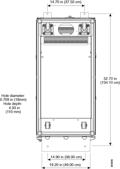
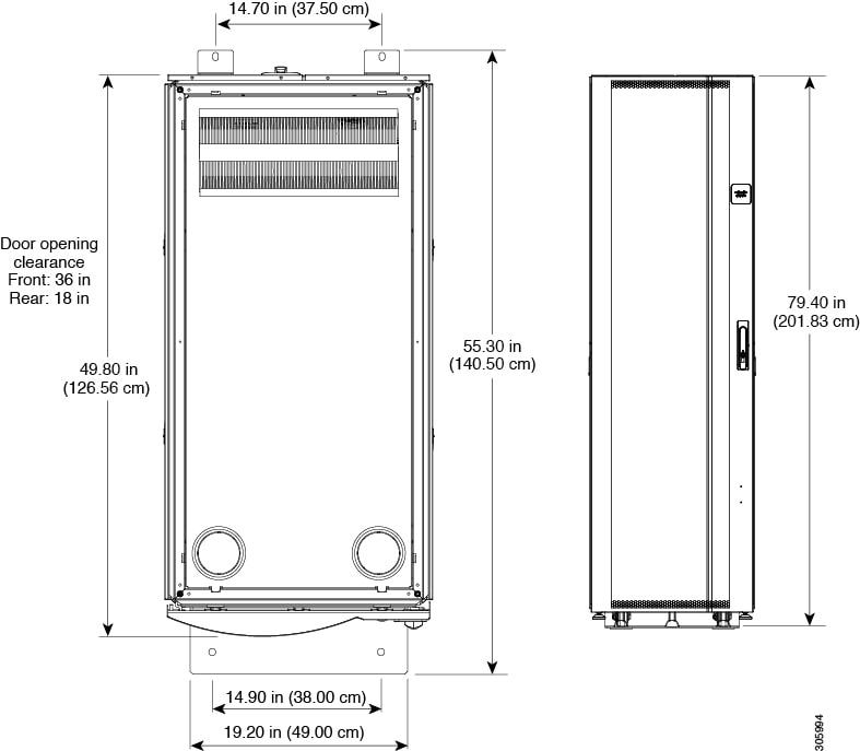
  • Choose an installation site that can accommodate the Cisco R42612 rack. To provide for future installation of a joined configuration, you should plan enough space for additional cabinets that occupy the same amount of space as the initial cabinet.

  • Make sure you have enough people to help you safely unload and install the system. A fully-loaded cabinet can weigh over 3000 lb (1360.8 kg) and moving it can present dangers to both personnel and the incorporate equipment.

  • Plan a smooth and unobstructed route from the off-loading site to the installation site. You should only move the rack when it is empty of all equipment.

  • Imperfections or obstructions in the floor between the unloading and installation site might hamper the movement of the unit. If you encounter an obstacle such as a sill or carpet, exercise care in navigating over it.

  • Verify that you have adequate standard tools on hand.

  • Ensure that your site contains an adequate power infrastructure.

Required Tools

You may need the following tools and equipment to install the Cisco R-Series Rack:

  • ESD-preventive wrist straps for each person

  • Phillips head screwdriver (#2)

  • 4 mm Hex driver

  • Pozidriv screwdriver

  • 3/8" or 1/2" flat-head screwdriver (to lower and raise stabilizers)

  • Adjustable wrench (for unbolting system)

  • Allen wrench (to disassemble caster assembly after the unit is sited)

  • Standard clippers or knife (to cut packaging binding)

  • Tape measure

  • Level

  • Anchoring bolts

  • Rotary hammer drill

  • Fork lift

  • Chain hoist

  • Documentation for the devices that you plan to install in the rack

Prepare the Subflooring (Optional)

To prepare your site for installation of the Cisco R42612 rack, you may need to reinforce the floor to support the rack when fully loaded with equipment. The following figure shows the reinforcement needed for secure anchoring of the rack.

Figure 1. Anchoring Pattern for the Cisco R42612 Rack

Note

It is your responsibility to fulfill local seismic safety standards.

Space and Clearances

The following figure shows the dimensions and space requirements for the Cisco R42612 rack.
Figure 2. Space and Clearance Dimensions

Plan for at least 3 feet of clearance in front of the Cisco R42612 rack to install servers or networking equipment. Refer to the documentation for the equipment you plan to use to find out how much clearance is needed at the rear for ventilation or other uses.

Planning Considerations

When planning your rack installation, consider the following guidelines:

  • Make sure that the system has adequate ventilation.

  • Always install the heaviest equipment as low as possible in the Cisco R4612 rack to maintain a low center of gravity and prevent the Cisco R42612 rack from falling over.

  • Use the cable management brackets and straps that are orderable for use with this system to keep cables organized and out of the way of the exhaust fans.

  • Make sure that cables do not impair access to other devices or require you to disconnect cables unnecessarily to perform equipment maintenance or upgrades.

  • To prevent device overheating, never install networking devices in a room that is not properly ventilated or air conditioned.

Safety Recommendations

The following guidelines are intended to help ensure your safety and protect the equipment. This list does not cover all potentially hazardous situations, so be alert.

  • Review the safety warnings listed in Regulatory Compliance and Safety Information document before installing, configuring, troubleshooting, or maintaining the Cisco R42612 rack.

  • Keep the area clear and dust free during and after the installation.

  • Keep tools and components away from areas where people might accidentally step on them or kick them.

  • Do not wear loose clothing, jewelry, or other items that might become trapped in the chassis during the installation.

  • As a safety feature, the Cisco PDUs ship with locking 3-wire electrical grounding-type plugs that only fit into grounding-type power outlets. The equipment grounding should be in accordance with national and local electrical codes.

  • Be sure to use the installed products in accordance with their marked electrical ratings and product usage instructions to guarantee safe operation.

Moving the Unit Safely


Note

Before you install the system, make sure that your site is properly prepared so that you can avoid having to move the Cisco R42612 rack later. Specifically, choose your installation site to accommodate existing power sources and network connections.


Whenever you move the Cisco R42612 rack or any heavy object, follow these guidelines:

  • Always disconnect all external cables before moving the Cisco R-Series rack.

  • Do not attempt to move the unit by yourself.

  • Never attempt to lift an object that might be too heavy for one person to lift alone. If you are not sure how much a particular object or device weights, refer to the appropriate device specifications.

  • Ensure that your footing is solid, and balance the weight of the object between your feet.

  • Move the system slowly; never move suddenly or twist your body as you push.

  • Keep your back straight and push with your legs, not your back. If you must bend down to move the Cisco R42612 rack, bend at the knees and not at the waist to reduce the strain on your lower back muscles.

  • Move the rack from the middle. Grasp the middle of the Cisco R-Series Rack exterior with both hands.

Safety with Electricity

Most networking and data center devices are designed to be removed and replaced without presenting an electrical hazard or damage. In situations where you must completely remove power to a component, always remove the plug on the component side first, and then unplug all components connected to a PDU before unplugging a PDU. Refer to the documentation for individual components for complete information about removing power from a component.

Follow these guidelines when working with any electrical equipment:

  • Install the Cisco R42612 rack in compliance with national and local electrical codes. In the United States, the relevant code is National Fire Protection Association (NFPA) 70, United States National Electrical Code. In Canada, the relevant code is Canadian Electrical Code, part I, CC22.1. In other countries, you should observe the standards of the International Electrotechnical Commission (IEC) 364, part 1 through part 7.

  • Remove all jewelry (including rings, necklaces, and watches) before working on equipment that is connected to power lines. Metal objects will heat up when connected to power and ground and can cause serious burns or weld the metal object to the terminals.

  • Locate the emergency power-off breaker switch for the room where you are working before starting any procedures that require access to the interior of the rack.

  • Disconnect all power and external cables before installing or removing a PDU or Cisco R42612 rack.

  • Do not work alone when potentially hazardous conditions exist.

  • Never assume that power has been disconnected from a circuit; always check.

  • Do not perform any action that creates a potential hazard to people or makes the equipment unsafe.

  • Never install equipment that appears damaged.

  • Carefully examine your work area for possible hazards such as moist floors, ungrounded power extension cables, and missing safety grounds.

In addition, use the following guidelines when working with any equipment that is disconnected from a power source, but still connected to network cabling.

  • Never install network wiring during a lightning storm.

  • Never install network jacks in a wet location unless the jack is specifically designed for wet locations.

  • Never touch non-insulated wires or terminals unless the line has been disconnected at the network interface.

  • Use caution when installing or modifying lines.

  • Read the installation instructions before you connect the system to its power source.


Warning

Connect the device to a grounded power outlet.


Warning

For Nordic countries (Norway, Finland, Sweden and Denmark) this system must be installed in a Restricted Access Location, where the voltage of the main ground connection of all equipment is the same (equipotential earth) and the system is connected to a grounded electrical outlet.


Warning

Read the installation instructions before using, installing or connecting the system to the power source.


Warning

This product relies on the building’s installation for short-circuit (overcurrent) protection. To reduce risk of electric shock or fire, ensure that the protective device is rated not greater than:


Warning

This equipment must be grounded. To reduce the risk of electric shock, never defeat the ground conductor or operate the equipment in the absence of a suitably installed ground conductor. Contact the appropriate electrical inspection authority or an electrician if you are uncertain that suitable grounding is available.


Preventing Electrostatic Discharge Damage

Electronic components are sensitive to Electrostatic discharge (ESD). ESD precautions should always be taken when handling electronic components. ESD damage occurs when electronic cards or components are improperly handled and can result in complete or intermittent system failures. Use an antistatic strap whenever handling electronic components. Touch the carriers edges only; never touch the boards or connector pins.


Note

Always tighten the captive installation screws when present. These screws prevent accidental removal, provide proper grounding for the system, and help ensure the bus connectors are properly seated.


Follow these guidelines to prevent ESD damage:

  • Always use an ESD wrist strap or ankle strap and ensure that it makes good skin contact.

  • When handling a removed component, make sure the equipment end of you ESD wrist strap is attached to an unfinished chassis surface of the device in which it is housed. Do not touch the printed circuit board, and avoid contact between the printed circuit board and your clothing.

  • Always place the component side up on an antistatic surface or in a static shielding bag. If you are returning the item to the factory, immediately place it in a static shielding bag.

  • Ensure that any plugin device are fully inserted and their captive installation screws are tightened. The captive installation screws prevent accidental removal and provide proper grounding for the system.


Note

For safety purposes, periodically check the resistance value of the antistatic strap. The measurement should be between 1 and 10 megaohms (Mohms).


Plant Wiring

When setting up the plant wiring and cabling at the site of the new system, consider the distance limitation imposed by power cable lengths and connector compatibility.

Environment Required

The Cisco R42612 rack and PDUs are operable beyond the specifications of the servers or networking equipment you are likely to install in them. Refer to the user documentation of the devices you will install to determine the required environment for these devices.

Environment specifications PDUs are in the following table.

Table 1. PDU Environmental Specifications

Item

Specification

Shipping or storage temperature

-40 to 60° C

Operating temperature

10 to 60° C

Shipping or storage relative humidity

5 to 95% (including condensing) with no droplets of liquid

Operating relative humidity

5 to 90% (including condensing)

Shipping or storage elevation

0 to 50,000 feet (0 to 15,240 meters)

Operating elevation

0 to 10,000 feet (0 to 3048 meters)

Acoustics

The unit does not produce significant sound

Most compute and networking equipment is designed to operate within the conditions as specified by The American Society of Heating, Refrigeration, and Air-Conditioning Engineers (ASHRAE).

ASHRAE has published a common set of guidelines for equipment manufacturers and data center designers to standardize on the following issues relating to a data center site:

  • Operating environments for classes of equipment

  • Equipment placement for optimum reliability and airflow

  • Tests of performance and the operational health of the data center

  • Equipment installation evaluations

  • Methodology for reporting power, cooling, and environmental specifications

These guidelines were developed by an industry consortium as part of the ASHRAE Technical Committee 9.9 and are presented in the 2004 report Thermal Guidelines for Data Processing Environment. These guidelines were updated in 2008 by the ASHRAE Environmental Guidelines for Datacom Equipment.

For information about ASHRAE and the report, see the ASHRAE website (http://www.ashrae.org).

Dust and Particles

Exhaust fans cool power supplies and system fan trays cool equipment by drawing in air and exhausting air out through various openings in the chassis. However, fans also ingest dust and other particles, causing contaminant buildup in the equipment and increased internal chassis temperature. A clean operating environment can greatly reduce the negative effects of dust and other particles that act as insulators and interfere with the mechanical components in the equipment.

Corrosion

The corrosion of equipment connectors is a gradual process that can eventually lead to intermittent failures of electrical circuits. The oil from your fingers or prolonged exposure to high temperature or humidity can corrode the gold-plated edge connectors and pin connectors on various components in the equipment. To prevent corrosion, avoid touching contacts on modules and protect the equipment from extreme temperatures and moist, salty environments.

Electromagnetic and Radio Frequency Interference

To reduce the possibility of EMI and RFI, follow these guidelines:

  • Cover all open slots with a metal filler.

  • Always use shielded cables with metal connector shells for attaching peripherals to the equipment.


Note

To predict and prevent strong EMI, you might need to consult experts in radio frequency interference (RFI).


Grounding

Electronic equipment is sensitive to variations in voltage supplied by the AC power source. Over voltage, under voltage, and transients (or spikes) can erase data from the memory or cause components to fail. To protect against these types of problems, you should always make sure that the racks that hold the servers or networking devices are grounded. When the rack are grounded, the equipment installed in them is automatically grounded. See the instructions for the products that you install in the rack for grounding steps. For additional information, see Installing the Grounding Kit.

Power Source

You should use dedicated power circuits (rather than sharing circuits with other heavy electrical equipment) for each PDU you install in the Cisco R42612 rack. The circuits must be rated for 30 A or 32 A, 200 to 250 VAC. The receptacles for these circuits should be within 6 feet (1.8 m) of each PDU when it is installed in the Cisco R42612 rack. Check the power at your site before installation and periodically after installation to ensure that you are receiving clean power. Install a power conditioner if necessary.

Power Requirements

Refer to the documentation for the power requirements for the devices you plan to install in the Cisco R42612 rack.

Site Preparation Checklist

Planning the location and layout of your equipment rack or wiring closet is essential for successful network operation, ventilation, and accessibility. The following table lists the site planning that we recommend completing before installing a Cisco R42612 rack or PDU.

Table 2. Site Planning Checklist

Task No.

Activity

Verified By

Time

Date

1

Space evaluation:
  • Space and layout

  • Floor covering

  • Impact and vibration

  • Lighting

  • Maintenance access

2

Environmental evaluation:
  • Ambient temperature

  • Humidity

  • Altitude

  • Atmospheric contamination

  • Air flow

3

Power evaluation:
  • Input power type

  • Power receptacles (verify that the power supply installed in the chassis has a dedicated AC source circuit)

  • Receptacle proximity to the equipment

  • Dedicated circuit for power supply

  • Dedicated (separate) circuits for redundant power supplies

  • Uninterruptable power supply (UPS) for power supplies

4

Grounding evaluation:
  • Circuit breaker size

  • Ground

5

Cable and interface equipment evaluation:
  • Cable type

  • Connector type

  • Cable distance limitations

  • Interface equipment (transceivers)

6

Electromagnetic interference (EMI) evaluation:
  • Distance limitations for signaling

  • Site wiring

  • Radio frequency interference (RFI)