Introduction
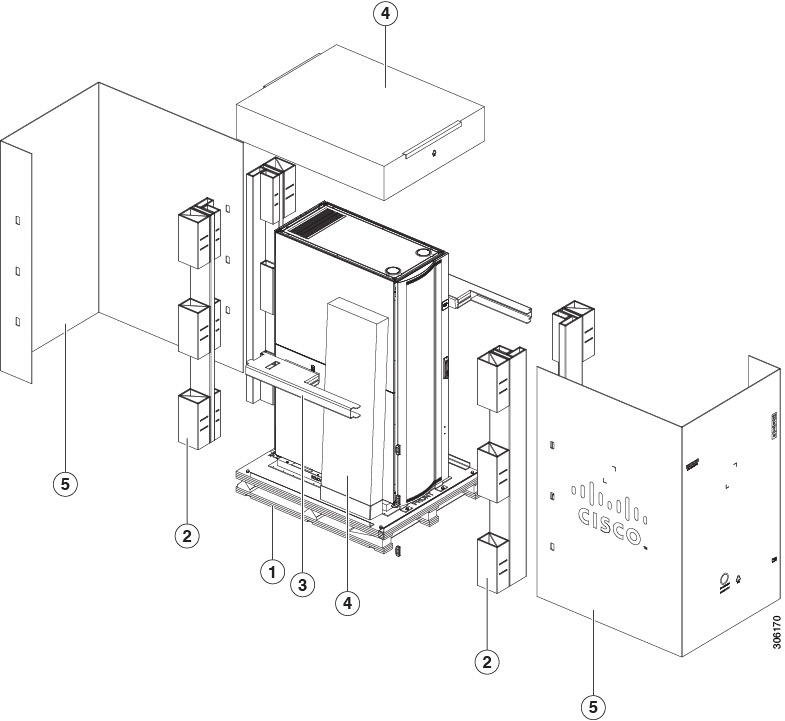
This chapter provides the guidelines for preintegrating and preracking Cisco UCS equipment in a Cisco R-Series Rack and all approved third-party racks. Use this information in conjunction with the following Cisco UCS product documentation:
-
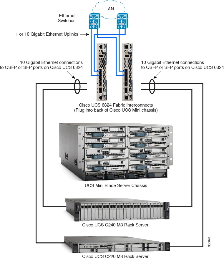
Cisco UCS 5108 Server Chassis Installation Guide (which covers both the UCS 5108 blade server chassis and the UCS Mini blade server chassis)
-
Cisco UCS 6300 Series Fabric Interconnect Hardware Installation Guide
-
Cisco UCS 6200 Series Fabric Interconnect Hardware Installation Guide
-
Cisco UCS C-Series Rack Servers Install and Upgrade Guides See the Installation and Service Guide for the particular rack server that you are installing.


 Feedback