- Preface
- Configuration Management
- Administering the Cisco ME 1200 NID
- Configuring Notifications
- Zero Touch Provisioning
- Configuring Synchronous Ethernet
- Configuring Ethernet Virtual Connections
- Configuring Switch Ports
- Configuring Spanning-Tree Protocol
- Configuring Link Aggregation Control Protocol (LACP)
- Provisioning Link Layer Discovery Protocol
- Configuring SNMP
- Configuring PTP
- Configuring ACLs
- Configuring Quality of Service (QoS)
- Configuring Ethernet OAM, Link OAM, and CFM
- Configuring Performance Monitoring
- Configuring EPS
- Configuring ERPS
- Configuring L2CP
- Configuring MAC Security
- Configuring NTP
- Configuring Storm Control
- Configuring Syslog
- Configuring SPAN
- Configuring RSPAN
- Configuring RFC 2544
- Configuring sFlow
- Configuring UDLD
- Configuring Flex Links
- Configuring Y.1564
- Configuring LST
- Configuring Security Access Control Lists
- Multicast Vlan Register
- Double-tagged management VLAN using IVID parameter
- Configuring LAG Aggregation
- Restrictions for ZTP
- ZTP Activation
- Step 1—Start ZTP
- Step 2—Reload Defaults
- Step 3—Get Management VLAN Configuration
- Step 4—Start the DHCP Client on the VLAN Interface
- Step 5—Download and Apply the Initial Configuration
- Step 6—Reverse DNS Lookup to Obtain Hostname
- Step 7—Download and Apply Specific Configuration
- Step 8—Copy Running Configuration to Startup Configuration
Zero Touch
Provisioning
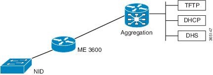
Zero Touch Provisioning (ZTP) automates configuration of Cisco ME 1200 Series Carrier Ethernet Access Device (hereafter known as Cisco ME 1200 NID) when it is deployed either in standalone operating mode or through a directly connected upstream user premise equipment such as Cisco ME3600/ME3800 or Cisco ASR920. When connected through a Cisco ME3600/ME3800 , provisioning of CE Services can be done from the remote controller mode. Otherwise, CLI on Cisco ME1200 NID can be accessed using SSH to provision CE Services once ZTP process is completed .
The ZTP process is activated by pressing the ZTP pinhole reset button found on the front of the Cisco ME 1200 NID. This minimizes manual operator intervention and helps reduce customers’ initial deployment costs.
 Note | The only interface for the ZTP is the ZTP button and the status LED, both found on the front of the Cisco ME 1200 NID. |
Restrictions for ZTP
ZTP Activation
Pressing the ZTP reset button triggers a series of steps that result in provisioning the Cisco ME 1200 NID with a complete, operational configuration.
- Start ZTP.
- Restore to factory defaults.
- Get management VLAN Configuration from LLDP-MED.
- Start the DHCP client on VLAN interface.
- Download and apply the initial configuration file from a location provided by the DHCP client.
- Use reverse DNS to obtain the host name of the device.
-
Download and apply a specific configuration file.
Note
Ensure that initial and specific configuration files are present on the TFTP server before starting the ZTP process. -
Copy the running configuration to startup configuration.
The following figure depicts the process pictorially:
Figure 2. ZTP Activation Process 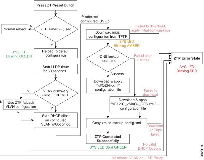
This process is explained in detail in the following sections.
ME 3600/ME 3800 Configuration
-
Configure the DHCP pool and add the TFTP and DNS configurations through DHCP options. The following is a sample DHCP pool: ip dhcp excluded-address 7.6.0.1 7.6.19.51 ip dhcp excluded-address 7.6.19.64 7.6.255.255 ip dhcp pool ztp-test network 7.6.0.0 255.255.255.0 default-router 7.6.0.10 -> Adding local SVI IP as default gateway for Cisco ME 1200 NID option 60 ascii ME1200-00-3A-99-FD-45-34 -> Adding Cisco ME 1200 NID MAC option 43 ip 7.0.0.221 -> Adding TFTP server option 67 ascii "ME1200_CFG" -> Adding initial configuration-file dns-server 7.0.0.217
-
Enable LLDP-MED network Policy TLV on the Cisco ME 3600X Series Ethernet Access Switch. Switch# interface gigabit 0/1 -> Physical port connected to Cisco ME 1200 NID Switch# lldp med-tlv-select network-policy Switch# lldp transmit Switch# lldp receive Switch# exit
-
Run LLDP. Switch# lldp run
- Configure an interface connecting to the 7.6.x.x switch and allowing VLAN (e.g. VLAN 10) to be used as management VLAN to ensure reachability to network gateway, or DHCP, TFTP, and DNS servers.
- Configure the interface connecting to Cisco ME 1200 NID as trunk.
- Assign management VLAN with the interface connecting to Cisco ME 1200 NID using the following command in global config mode
Switch# platform nid-controller assign vlan 10 gigabitEthernet 1/1
- Step 1—Start ZTP
- Step 2—Reload Defaults
- Step 3—Get Management VLAN Configuration
- Step 4—Start the DHCP Client on the VLAN Interface
- Step 5—Download and Apply the Initial Configuration
- Step 6—Reverse DNS Lookup to Obtain Hostname
- Step 7—Download and Apply Specific Configuration
- Step 8—Copy Running Configuration to Startup Configuration
Step 1—Start ZTP
Note | If the ZTP reset button is pressed for less than five seconds, a cold reload is issued. |
Note | When one instance of the ZTP activation is active, another instance cannot be started. Wait for the ZTP activation to complete (check ZTP status using LED to determine if it was successful or moved to error state) before starting the process again. |
Step 2—Reload Defaults
When ZTP activation is triggered, it causes the Cisco ME 1200 NID to reload with a default configuration that includes LLDP MED endpoint connectivity mode on all ports.
The Cisco ME 1200 NID may have links on several ports when the ZTP activation is started. All such ports are candidates for being used for the ZTP activation, and must be ready to receive the LLDP-MED TLV, where a packet is sent on a point-to-point link with a well-known multicast destination MAC.
The LLDP-MED information is sent every 30 seconds. To ensure that all ports receive the LLDP-MED TLV, a 60-second timer starts the count down for LLDP initialization on all ports.
Step 3—Get Management VLAN Configuration
VLAN Discovery using remote ME 3600x device
The first step after ZTP reload is the discovery of a management VLAN between the User-Facing Premise Equipment such as the Cisco ME 3600X Series Ethernet Access Switch, and one or more Cisco ME 1200 NIDs. In this step, the LLDP-MED is used to acquire the management VLAN configuration.
The Cisco ME 1200 NID can be configured to act either as an end-point or a connectivity link. The default configuration type is an end-point, where all ports are scanned for received LLDP-MED broadcast. However, only those ports that have received a network policy with voice application type are considered. These ports are configured accordingly, and a VLAN interface is created on the defined VLAN.
If If none of the ports received LLDP-MED TLVs after 60 seconds, or interface on ME 3600x is not configured to allow a specific management VLAN, ZTP process tries to configure a fallback VLAN as described below. Hence it is better to check configurations and ensure there is no network connectivity issue while in this step.
VLAN Discovery in standalone operating mode
If Cisco ME1200 NID is deployed without ME 3600x or directly connected switch upstream, which does not support LLDP-MED Network Policy TLV, a fallback mechanism is used to complete VLAN discovery. This assumes that an external DHCP server is present on the network, which can support DHCP Option 60 and 43, and allocate IP address to ME1200 (Note: Option 60 unique identifier string will be of the form "ME1200-00-3A-99-FD-45-34", where 00:3a:99:fd:45:34 is a sample MAC address of the Cisco ME1200.
The fallback VLAN discovery can be described as follows:
- When ZTP is triggered using
the push button on Cisco ME 1200 NID, a special, default configuration is
loaded , which includes the following commands:
ztp fallback vlan 1-4095 frame-type tagged interface Gi 1/1-6
ztp fallback vlan 1 frame-type untagged interface Gi 1/1-6
This causes DHCP replies coming from an external DHCP server to be processed by Cisco ME1200 NID. - If a DHCP OFFER containing a VLAN tag in the range of 1-4095, or DHCP OFFER on VLAN 1 (untagged) is received on any one of the ports 1-6, it is used to determine management VLAN.
- To avoid a flood of DHCP messages from being intercepted by ME1200, only DHCP replies containing DHCP Option 60 & 43 are intercepted.
The VLAN that is determined from this fallback mechanism is used in subsequent steps of the ZTP process.
Note | The default fallback VLAN configuration can also be modified by user and the modified configuration allowed to persist across reloads. From the DHCP pool network range and deployment, user may know a priori of the VLAN or range of VLANs from which OFFERs are sent by DHCP server. Hence it is recommended to modify fallback VLAN configuration from default to a reasonable VLAN range. Example 1: If DHCP server is on VLAN 400 and it's connecting port type is tagged, following configuration change during initial Cisco ME1200 NID configuration will cause DHCP OFFERs on VLAN 400 to be processed when ZTP is triggered in standalone mode.ztp fallback vlan 400 frame-type tagged interface Gi 1/1-6If DHCP server is directly connected to one of the interfaces (say, interface 5), this configuration can be modified further as: ztp fallback vlan 400 frame-type tagged interface Gi 1/5 |
Example 2:
ztp fallback vlan 100 frame-type untagged interface Gi 1/1-6
Note | Only a single VLAN can be configured if port-type is untagged. |
no ztp fallback vlan
Once configuration is modified for above steps, user can copy running-config to startup-config prior to ZTP reset. This will cause modified fallback configuration to be present when ZTP process is restarted.
ZTP for Cisco ME 1200 NIDs in Linear Topology
If the network topology involves one or more Cisco ME 1200 NID downstream from the Cisco ME 1200 NID connected to ME 3600 , the following steps are required to ensure ZTP works as expected. In this case, each Cisco ME 1200 NID is connected to the upstream Cisco ME 1200 NID through a point-to-point link.
For ZTP to work in this topology, you must trigger ZTP reset on the downstream Cisco ME 1200 NID after ZTP has successfully completed on the upstream Cisco ME 1200 NID.
In addition, before ZTP button is pressed on the downstream Cisco ME 1200 NID, the upstream Cisco ME 1200 NID which has just completed ZTP successfully requires a change in LLDP-MED device type—from endpoint to network connectivity. This single manual step is required to further propagate LLDP towards the downstream Cisco ME 1200 NID.
Consider the following topology:
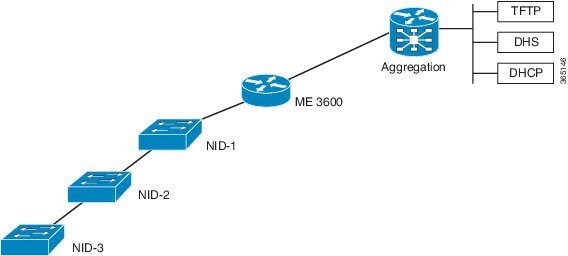
Configuration on Cisco ME 1200 NID1 Before Starting the ZTP Process on Cisco ME 1200 NID2:
Switch# lldp med media-vlan-policy 1 voice tagged 10 l2-priority 0 dscp 0
interface GigabitEthernet 1/4
 switchport mode trunk
 lldp med media-vlan policy-list 1   -> Assigning media VLAN policy
 lldp med type connectivity          -> Configuring NID1 as network device
 no spanning-tree
 lldp transmit                       -> LLDP transmission is enabled
 lldp receive                        -> LLDP reception is enabled
 Tip | The above configuration can be included in the Cisco ME 1200 NID1 final configuration file to avoid manual configuration after ZTP on Cisco ME 1200 NID1. |
ZTP for Cisco ME 1200 NIDs in a Ring Topology
Consider the following topology:
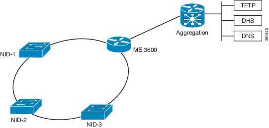
In this deployment, while Cisco ME 1200 NID-1 receives VLAN through LLDP-MED Network Policy TLV and initiates DHCP Discovery, the Cisco ME 1200 NIDs that are downstream to Cisco ME 1200 NID-1 do not receive LLDP-MED TLVs. This is because LLDP-MED TLVs are sent only between endpoint devices and are not propagated beyond Cisco ME 1200 NID-1.
To allow LLDP-MED TLVs to be propagated to all downstream Cisco ME 1200 NIDs once Cisco ME 1200 NID-1 completes VLAN discovery, modify the port configuration in the same manner as the linear chain topology deployment.
Step 4—Start the DHCP Client on the VLAN Interface
A DHCP client is started on all the VLAN interfaces created in the previous step. To identify itself as a device undergoing ZTP, the DHCP client on Cisco ME 1200 NID adds DHCP Option 60 to the DHCPDISCOVER/DHCPREQUEST messages on the newly-discovered management VLAN, that it sends to the DHCP server.
The Option 60 Vendor Class Identifier in DHCPDISCOVER/DHCPREQUEST message is encoded as a unique ASCII string formed by concatenating the string "ME1200" with the complete Cisco ME 1200 NID MAC address in the form similar to ME1200-XX- XX-XX-XX-XX-XX, for example, ME1200-00-01-C1-00-00-00. In addition, as part of the parameters list sent in DHCPREQUEST, Cisco ME 1200 NID also requests the DHCP server to send following options:
-
Option 43—This option is used by client to accept the DHCP ACK only from DHCP server or the ME 3600x devicespecifically configured for it. The Vendor Specific Information in Option 43 is the IP address of the TFTP server that contains the configuration file.
-
Option 67—This is the startup configuration filename.
- Option 3—Default gateway
- Option 6—DNS Server
Note
Options 60, 43, and 67 are not used when the DHCP client is used in a non-ZTP mode.
Wait for the DHCP Client(s) to Enter the Bound State
Note | If no DHCP client reaches bound state with the requested options within 120 seconds, ZTP activation process enters error state. |
Once the connectivity is established between the Cisco ME 1200 NID and the ME 3600x device, the Cisco ME 1200 NID can be remotely managed from the ME 3600x device.
A database of NID instances, MAC addresses, IP addresses, TFTP server, attached physical ports is maintained on the ME 3600x device. This information can be used for management of selected Cisco ME 1200 NIDs.
The association between the Cisco ME 1200 NID and ME 3600x device is maintained by sending and receiving periodic IP-based heartbeat messages.
Step 5—Download and Apply the Initial Configuration
When the DHCP client on the Cisco ME 1200 NID receives the DHCPACK, it uses the information from Option 43 and Option 67 from the DHCP client to download the initial configuration file. This configuration file is intended as a pre-staging configuration, containing basic reachability information such as the gateway, TFTP, DNS server, or the default VLAN configuration so that one or more NIDs can be added to network prior to ZTP auto-configuration. But if there is no requirement, this can be an empty configuration file. The intention of this step is to ensure that ME1200 NID can be reachable to gateway, TFTP, DNS servers. The filename should be specified as an ASCII string using Option 67 in DHCP pool configuration on UPE.
If the download operation fails or if the configuration could not be applied, the ZTP process enters the error state.
Note | The value of the Option 67 field will be taken as the configuration filename, including any file extension. |
Step 6—Reverse DNS Lookup to Obtain Hostname
Using the IP address of the DHCP client and the DNS server provided by the DHCP client the Cisco ME 1200 NID performs a reverse DNS query to derive its host name. When the host name is derived, it is added to the current running configuration.
In case of failure, the reverse DNS process is retried five times. After five retries, the host name is configured with the MAC address of the device encoded in the format as: 00_01_C1_00_00_00 (hex string values in uppercase), where 00:01:C1:00:00:00 is a sample ME1200 NID MAC address. This allows ZTP process to continue.
Step 7—Download and Apply Specific Configuration
The reverse zone must include the PTR record with IP address-name mapping.
Note | FQDN is set as hostname at the end of this step. |
The following is a sample DNS configuration:
NS    nid1.example.com
A    192.168.2.100
nid1    IN    A 192.168.2.100
nid2    IN    A 192.168.2.101
nid3    IN    A 192.168.2.102
nid4    IN    A 192.168.2.103
...

2.168.192.in-addr.arpa.
PTR    server.example.com.
101    IN    PTR    nid2.example.com.
102    IN    PTR    nid3.example.com.
103    IN    PTR    nid4.example.com.
NID_MAC_ADDR_CFG.xml
For example, 00_3B_99_FE_5E_00_CFG.xml(hex string values in uppercase)
If there is no file stored in .xml format, then ZTP process enters the error state. In the error state, status LED is set to blinking red.
Note | It is recommended that user makes 2 file copies of the saved, intended configuration - one named as per the FQDN, such as nid2.example.com.xml, and the other based on the MAC address, such as 00_3B_99_FE_5E_00_CFG.xml. |
Step 8—Copy Running Configuration to Startup Configuration
The first time ZTP is performed, you must store a default xml configuration in the fqdn.xml derived from rDNS and in NID_MAC_ADDR_CFG.xml. The following is the content of this default xml file:
<?xml version="1.0" encoding="UTF-8"?>
<SOAP-ENV:Envelope xmlns:xsi="http://www.w3.org/2001/XMLSchema-instance" xmlns:ns0="http://new.webservice.namespace" xmlns:SOAP-ENV="http
://schemas.xmlsoap.org/soap/envelope/">
   <SOAP-ENV:Body>
      <run_cfg_resp>
      </run_cfg_resp>
   </SOAP-ENV:Body>
</SOAP-ENV:Envelope>
Only after this configuration is applied on Cisco ME 1200 NID, Step 8 will generate a complete XML configuration and store the file as flash:startup-config.xml. This file can be used to replace the default configuration in fqdn.xml and NID_MAC_ADDR_CFG.xml as required.
As a last step in ZTP activation, the running configuration (which was the result of Cisco ME 1200 NID-specific configuration applied after reverse DNS and TFTP download) is copied to startup configuration (flash:startup-config.xml). This ensures that running configuration is persistent.
If there is an error in copying the configuration, the ZTP process enters the error state.
The ZTP process has completed, the status LED is set to solid green.
 Feedback