Connector and Cable Specifications
Connector Specifications
10/100
The 10/100 Ethernet ports use standard RJ-45 connectors and Ethernet pinouts with internal crossovers. These ports have the send (TD) and receive (RD) signals internally crossed so that a twisted-pair straight-through cable and adapter can be attached.
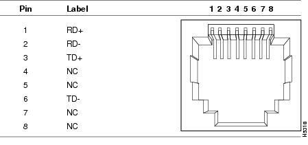
When connecting 10/100 ports to devices such as servers, workstations, and routers, you can use a two or four twisted-pair straight-through cable wired for 10BASE-T and 100BASE-TX. Figure 59 shows the two twisted-pair straight-through cable schematics. Figure 61 shows the four twisted-pair straight-through cable schematics.
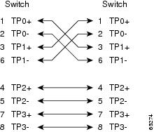
When connecting the ports to other devices, such as switches or repeaters, you can use a two or four twisted-pair crossover cable. Figure 60 shows the two twisted-pair crossover cable schematics. Figure 62 shows the four twisted-pair crossover cable schematics.
If auto-MDIX is disabled, use a straight-through cable to connect ports when only one port is labeled with an X. Use a crossover cable to connect ports when both ports are labeled with an X or when both ports are not labeled with an X.
You can use Category 3, 4, or 5 cabling when connecting to 10BASE-T-compatible devices. You must use Category 5 (or higher) cabling when connecting to 100BASE-TX-compatible devices.
Note: You can use the mdix auto interface configuration command in the CLI to enable the automatic medium-dependent interface crossover (auto-MDIX) feature. When the auto-MDIX feature is enabled, the switch detects the required cable type for copper Ethernet connections and configures the interfaces accordingly. Therefore, you can use either a crossover or a straight-through cable for connections to a copper 10/100, 10/100/1000, or 1000BASE-T SFP module port on the switch, regardless of the type of device on the other end of the connection.
SFP Module Connectors
Figure 55 shows the MT-RJ SFP module fiber-optic connector.
Figure 55 Fiber-Optic SFP Module LC Connector
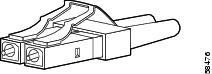
Warning: Invisible laser radiation may be emitted from disconnected fibers or connectors. Do not stare into beams or view directly with optical instruments. Statement 1051
Figure 56 shows the 1000BASE-T SFP module RJ-45 connector.
Figure 56 1000BASE-T SFP Module Connector
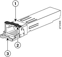
| Bale-clasp latching mechanism in the open (unlocked) position |
|||
| Bale-clasp latching mechanism in the closed (locked) position |
Dual-Purpose Ports
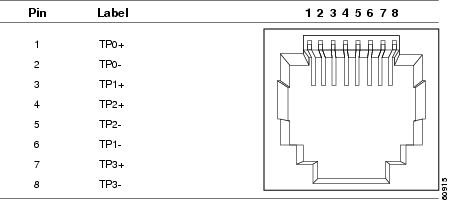
The 10/100/1000 Ethernet ports on the dual-purpose ports use RJ-45 connectors.
Figure 57 10/100/1000 Port Pinouts
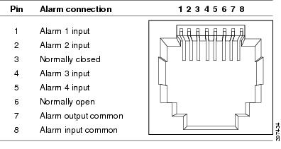
Alarm Port
The alarm port uses an RJ-45 connector. See the Alarm Ports for more information. For information on alarm ratings, see the Alarm Ratings.
Cables and Adapters
SFP Module Cables
Each port must match the wave-length specifications on each end of the cable, and for reliable communications, the cable must not exceed the allowable length. Copper 1000BASE-T SFP transceivers use standard four twisted-pair, CAT5 (or greater) cable at lengths up to 328 feet (100 meters).
■![]() The maximum operating temperature of the switch varies depending on SFP module type. See Table 2 for information on the supported temperature ranges.
The maximum operating temperature of the switch varies depending on SFP module type. See Table 2 for information on the supported temperature ranges.
■![]() Modal bandwidth applies only to multimode fiber (MMF).
Modal bandwidth applies only to multimode fiber (MMF).
■![]() A mode-field diameter/cladding diameter = 9 micrometers/125 micrometers.
A mode-field diameter/cladding diameter = 9 micrometers/125 micrometers.
■![]() 1000BASE-LX/LH SFP modules connected with MMF over a short link distance require a mode-conditioning patch cord.
1000BASE-LX/LH SFP modules connected with MMF over a short link distance require a mode-conditioning patch cord.
Ordinary patch cords can cause transceiver saturation, resulting in an elevated bit error rate (BER). Using the 1000BASE-LX/LH SFP module with 62.5-micron diameter multimode fiber (MMF) requires a mode-conditioning patch cord between the single mode fiber (SMF) SFP module and the MMF cable on both the send and receive link ends.
■![]() Link distances greater than 984 feet (300 m) require a mode-conditioning patch cord.
Link distances greater than 984 feet (300 m) require a mode-conditioning patch cord.
■![]() 1000BASE-ZX SFP modules can send data up to 62 miles (100 km) by using dispersion-shifted SMF or low-attenuation SMF. The distance depends on fiber quality, the number of splices, and the connectors.
1000BASE-ZX SFP modules can send data up to 62 miles (100 km) by using dispersion-shifted SMF or low-attenuation SMF. The distance depends on fiber quality, the number of splices, and the connectors.
■![]() When the fiber-optic cable span is less than 15.43 miles (25 km), insert a 5-decibel (dB) or 10-dB inline optical attenuator between the fiber-optic cable plant and the receiving port on the 1000BASE-ZX SFP module.
When the fiber-optic cable span is less than 15.43 miles (25 km), insert a 5-decibel (dB) or 10-dB inline optical attenuator between the fiber-optic cable plant and the receiving port on the 1000BASE-ZX SFP module.
|
|
|
|
|
|
|
|---|---|---|---|---|---|
|
|
|||||
|
|
|||||
|
|
|||||
Cable Pinouts
Figure 59 Two Twisted-Pair Straight-Through Cable Schematic for 10/100 Ports
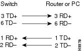
Figure 60 Two Twisted-Pair Crossover Cable Schematic for 10/100 Ports
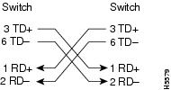
Figure 61 Four Twisted-Pair Straight-Through Cable Schematic for 1000BASE-T Ports
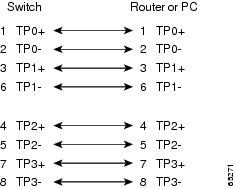
Figure 62 Four Twisted-Pair Crossover Cable Schematics for 1000BASE-T Ports
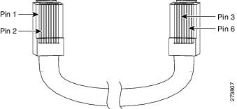
To identify a crossover cable, hold the cable ends side-by-side, with the tab at the back. The wire connected to pin 1 on the left end should be the same color as the wire connected to pin 3 on the right end. The wire connected to pin 2 on the left end should be the same color as the wire connected to pin 6 on the right end.
Figure 63 Identifying a Crossover Cable
Console Port Adapter Pinouts
The console port uses an 8-pin RJ-45 connector, which is described in Table 21 and Table 22. If you did not order a console cable, you need to provide an RJ-45-to-DB-9 adapter cable to connect the switch console port to a PC console port. You need to provide an RJ-45-to-DB-25 female DTE adapter if you want to connect the switch console port to a terminal. You can order an adapter (part number ACS-DSBUASYN=). For console port and adapter pinout information, see Table 21 and Table 22.
Table 21 lists the pinouts for the console port, the RJ-45-to-DB-9 adapter cable, and the console device.
|
|
|
|
|---|---|---|
|
|
|
|
Table 22 lists the pinouts for the switch console port, RJ-45-to-DB-25 female DTE adapter, and the console device.
Note: The RJ-45-to-DB-25 female DTE adapter is not supplied with the switch. You can order this adapter from Cisco (part number ACS-DSBUASYN=).
|
|
|
|
|---|---|---|
|
|
|
|
 Feedback