Troubleshooting
This chapter provides these topics for troubleshooting problems:
Diagnosing Problems
The LEDs on the front panel provide troubleshooting information about the switch. They show power-on self-test (POST) failures, port-connectivity problems, and overall switch performance. You can also get statistics from the browser interface, the command-line interface (CLI), the Cisco Intelligence
Engine 2100 (IE2100) Series Configuration Registrar, or a Simple Network Management Protocol (SNMP) workstation. See the switch software configuration guide, the switch command reference, or the documentation that came with your IE2100 or SNMP application for details.
Verify Switch POST Results
As the switch powers on, it begins the POST, a series of tests that runs automatically to ensure that the switch functions properly. It might take several minutes for the switch to complete POST.
POST starts with LED tests that cycles once through the System, Alarm, Setup, Pwr A, and Pwr B LEDs. While POST proceeds, the System LED blinks green, and all the other LEDs remain off. If POST completes successfully, the System LED changes to solid green, and the other LEDs display their normal operating status. If the switch fails POST, the System LED turns red.

Note![]() POST failures are usually fatal. Contact your Cisco technical support representative if your switch does not pass POST.
POST failures are usually fatal. Contact your Cisco technical support representative if your switch does not pass POST.
If you have a terminal connected to the console port, you can also view POST status and test results on the terminal. If the terminal displays garbled characters, you might need to reset the terminal-emulation software to 9600 bits per second. For more information about viewing results on a terminal, see the “Verify POST Results” section.

Warning![]() If you connect or disconnect the console cable with power applied to the switch or any device on the network, an electrical arc can occur. This could cause an explosion in hazardous location installations. Be sure that power is removed or the area is nonhazardous before proceeding.
If you connect or disconnect the console cable with power applied to the switch or any device on the network, an electrical arc can occur. This could cause an explosion in hazardous location installations. Be sure that power is removed or the area is nonhazardous before proceeding.
To verify switch operation, perform POST on the switch in a nonhazardous location before installation. Statement 1065
Verify Switch LEDs
If you have physical access to the switch, look at the port LEDs for information about the switch. See the “LEDs” section for a description of the LED colors and their meanings.
Verify Switch Connections
Review this section when troubleshooting switch connection problems.
Bad or Damaged Cable
Always make sure that the cable does not have marginal damage or failure. A cable might be connect at the physical layer, but it could corrupt packets as a result of subtle damage to the wiring or connectors. If the port has many packet errors or the port constantly flaps (loses and regains link):
- Exchange the copper or fiber-optic cable with a known, good cable.
- Look for broken, bent, or missing pins on cable connectors.
- Rule out any bad patch panel connections or media convertors between the source and destination. If possible, bypass the patch panel, or eliminate faulty media convertors (fiber-optic-to-copper).
- Try the cable in another port or interface, if possible, to see if the problem follows the cable.
Ethernet and Fiber Cables
Make sure that you have the correct cable type for the connection:
Use either Category 5, Category 5e, or Category 6 UTP for 10/100 or 10/100/1000 Mb/s connections.
Verify that you have the correct cable for the distance and the port type. Make sure that the connected device ports both match and use the same type encoding, optical frequency, and fiber type. For more information about cabling, see the “Cable and Adapter Specifications” section.
Determine if a crossover cable was used when a straight-through was required or the reverse. Enable auto-MDIX on the switch, or replace the cable. See the “Cable and Adapter Specifications” section for recommended Ethernet cables.
Link Status
Verify that both sides have link. A single broken wire or one shutdown port can cause one side to show link, but the other side does not have link.
A link LED does not guarantee that the cable is fully functional. The cable might have encountered physical stress that causes it to function at a marginal level. If the link light for the port does not come on:
- Connect the cable from the switch to a known good device.
- Make sure that both ends of the cable are connected to the correct ports.
- Verify that both devices have power.
- Verify that you are using the correct cable type. See the“Cable and Adapter Specifications” section for more information.
- Rule out loose connections. Sometimes a cable appears to be seated, but is not. Disconnect the cable, and then reconnect it.
Transceiver Issues
Use only Cisco SFP modules on the switch. Each Cisco module has an internal serial EEPROM that is encoded with security information. This encoding provides a way for Cisco to identify and validate that the module meets the requirements for the switch. Check these items:
- Bad or wrong SFP module. Exchange the suspect module with a known good module. Verify that the module is supported on this platform. (The switch release notes on Cisco.com list the SFP modules that the switch supports.)
- Use the show interfaces privileged EXEC command to verify the port or module error-disabled, disabled, or shutdown status. Re-enable the port if needed.
- Make sure that all fiber connections are properly cleaned and securely connected.
Port and Interface Settings
A cause of port connectivity failure can be a disabled port. Verify that the port or interface is not disabled or powered down for some reason. If a port or interface is manually shut down on one side of the link or the other side, the link does not come up until you re-enable the port. Use the show interfaces privileged EXEC command to verify the port or interface error-disabled, disabled, or shutdown status on both sides of the connection. If needed, re-enable the port or the interface.
Ping End Device
Test the end device by pinging from the directly connected switch first, and then work your way back port by port, interface by interface, trunk by trunk, until you find the source of the connectivity issue. Make sure that each switch can see the end device MAC address in its content-addressable memory (CAM) table.
Spanning Tree Loops
Spanning Tree Protocol (STP) loops can cause serious performance issues that look like port or interface problems. In this situation, the switch bandwidth is used over and over again by the same frames, leaving little room for legitimate traffic.
Loops can be caused by a unidirectional link. A unidirectional link occurs whenever the traffic sent by the switch is received by its neighbor, but the traffic from the neighbor is not received by the switch. A broken fiber-optic cable, other cabling, or a port issue could cause this one-way communication.
You can enable UniDirectional Link Detection (UDLD) on the switch to help identify difficult-to-find unidirectional link problems. UDLD supports two modes of operation: normal (the default) and aggressive. In normal mode, UDLD detects unidirectional links due to misconnected interfaces on fiber-optic connections. In aggressive mode, UDLD also detects unidirectional links due to one-way traffic on fiber-optic and twisted-pair links and due to misconnected interfaces on fiber-optic links. For information about enabling UDLD on the switch, see the “Understanding UDLD” section in the “Configuring UDLD” chapter of the software configuration guide for this release.
Verify Switch Performance
Review this section when troubleshooting switch performance problems.
Speed, Duplex, and Autonegotiation
If the port statistics show a large amount of alignment errors, frame check sequence (FCS), or late-collisions errors, this might indicate a speed or duplex mismatch.
A common issue with speed and duplex is when the duplex settings are mismatched between two switches, between a switch and a router, or between the switch and a workstation or server. This can happen when manually setting the speed and duplex or from autonegotiation issues between the two devices. A mismatch occurs under these circumstances:
- A manually set speed or duplex parameter is different from the manually set speed or duplex parameter on the connected port.
- A port is set to autonegotiate, and the connected port is set to full duplex with no autonegotiation.
To maximize switch performance and ensure a link, follow one of these guidelines when changing the settings for duplex and speed:
- Let both ports autonegotiate both speed and duplex.
- Manually set the speed and duplex parameters for the ports on both ends of the connection.
- If a remote device does not autonegotiate, configure the duplex settings on the two ports to match. The speed parameter can adjust itself even if the connected port does not autonegotiate.
Autonegotiation and NIC
Problems sometimes occur between the switch and third-party network interface cards (NICs). By default, the switch ports and interfaces are set to autonegotiate. It is common for devices like laptops or other devices to be set to autonegotiate as well, yet sometimes autonegotation issues occur.
To troubleshoot autonegotiation problems, try manually setting both sides of the connection. If this does not solve the problem, there could be a problem with the firmware or software on your NIC. You can resolve this by upgrading the NIC driver to the latest version available from the manufacture.
Cabling Distance
If the port statistics show excessive FCS, late-collision, or alignment errors, verify that the cable distance from the switch to the connected device meets the recommended guidelines. See the “Cable and Connectors” section for cabling guidelines.
How to Clear the Switch IP Address and Configuration
Follow these steps to return your switch to the factory default settings. These are reasons why you might want to reset the switch:
- You installed the switch in your network and cannot connect to it because you assigned the wrong IP address.
- You want to clear all configurations from the switch and assign a new IP address.
- You want to reset the password on the switch.

To reset the password on the switch:
2.![]() Power on the switch, and at the same time, press and hold down the Express Setup button until all the system LEDs turn red.
Power on the switch, and at the same time, press and hold down the Express Setup button until all the system LEDs turn red.
3.![]() Release the Express Setup button, and the switch continues to boot.
Release the Express Setup button, and the switch continues to boot.
After the switch restarts, continue to run Express Setup.
The switch now behaves like an unconfigured switch. You can configure the switch by using Express Setup as described in the getting started guide that is included with the switch. You can also configure the switch by using the CLI setup procedure described in Appendix D, “Configuring the Switch with the CLI-Based Setup Program.”
How to Recover Passwords
Password recovery is a feature that a system administrator can enable or disable. If password recovery is disabled, the only way to recover from a lost or forgotten password is to clear the switch configuration entirely. For this procedure, see the “How to Clear the Switch IP Address and Configuration” section.
The switch software configuration guide provides details about enabling and disabling the password recovery feature and the procedure for recovering passwords.
Finding the Switch Serial Number
If you contact Cisco Technical Assistance, you need to know the serial number of your switch. See Figure 3-1 and Figure 3-2 to find the serial number on your switch or module. See Figure 3-3 to find the serial number on your power converter. You can also use the show version privileged EXEC command to get the switch serial number.
Figure 3-1 Serial Number Location for the Cisco IE-3000-4TC and the Cisco IE-3000-8TC Switch
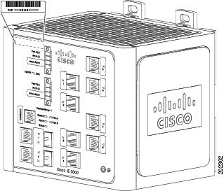
Figure 3-2 Serial Number Location for the Cisco IEM-3000-8TM and the Cisco IEM-3000-8FM Module
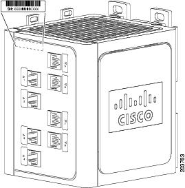
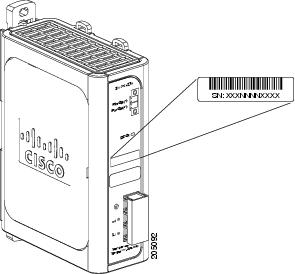
Figure 3-3 Serial Number Location for the Cisco PWR-IE3000-AC Power Converter
 Feedback