Cable and Connectors
This appendix describes the switch ports and the cables and adapters that you use to connect the switch to other devices.
Connector Specifications
These sections describe the connectors used with the Cisco IE 3000 switch.
10/100 Ports
The 10/100 and 10/100/1000 Ethernet ports on switches use standard RJ-45 connectors and Ethernet pinouts with internal crossovers. Figure C-1 and show the pinouts.
The auto-MDIX feature described briefly in this guide is enabled by default. For configuration information for this feature, see the switch software configuration guide or the switch command reference.
The PoE ports on the PoE expansion modules integrate power and data signals on the same wires. The ports use standard RJ-45 connectors and Ethernet pinouts with internal crossovers. Figure C-1 shows the pinouts.
Connecting to 10BASE-T- and 100BASE-TX-Compatible Devices
When connecting the ports to 10BASE-T- and 100BASE-TX-compatible devices, such as servers, workstations, and routers, you can use a two or four twisted-pair, straight-through cable wired for 10BASE-T and 100BASE-TX. Figure C-5 shows the two twisted-pair, straight-through cable schematics. Figure C-7 shows the four twisted-pair, straight-through cable schematics.
When connecting the ports to 10BASE-T- and 100BASE-TX-compatible devices, such as switches or repeaters, you can use a two or four twisted-pair, crossover cable. Figure C-6 shows the two twisted-pair, crossover cable schematics. Figure C-8 shows the four twisted-pair, crossover cable schematics.
You can use Category 3, 4, or 5 cabling when connecting to 10BASE-T-compatible devices. You must use Category 5 cabling when connecting to 100BASE-TX-compatible devices.
Connecting to 1000BASE-T Devices
When connecting the ports to 1000BASE-T devices, such as servers, workstations, and routers, you must use a four twisted-pair, Category 5, straight-through cable wired for 10BASE-T, 100BASE-TX, and 1000BASE-T. Figure C-7 shows the straight-through cable schematics.
When connecting the ports to other devices, such as switches or repeaters, you must use a four twisted-pair, Category 5, crossover cable. Figure C-8 shows the crossover cable schematics.

Note![]() Use a straight-through cable to connect two ports only when one port is designated with an X. Use a crossover cable to connect two ports when both ports are designated with an X or when both ports do not have an X.
Use a straight-through cable to connect two ports only when one port is designated with an X. Use a crossover cable to connect two ports when both ports are designated with an X or when both ports do not have an X.
Figure C-1 10/100 Port Pinouts
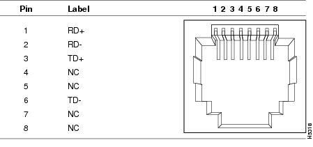
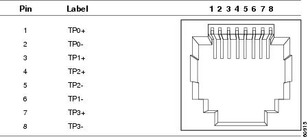
Figure C-2 10/100/1000 Port Pinouts
100BASE-FX Ports
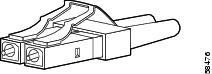
The 100BASE-FX ports use MT-RJ connectors. See Figure C-3. The 100BASE-FX ports use 50/125- or 62.5/125-micron multimode fiber-optic cabling.
Figure C-3 Fiber-Optic SFP Module LC Connector

Warning![]() Invisible laser radiation may be emitted from disconnected fibers or connectors. Do not stare into beams or view directly with optical instruments.
Invisible laser radiation may be emitted from disconnected fibers or connectors. Do not stare into beams or view directly with optical instruments.
PoE Expansion Module Ports (IEM-3000-4PC and IEM-3000-4PC-4TC Only)
This section applies only to the Cisco IEM-3000-4PC and the Cisco IEM-3000-4PC-4TC PoE expansion modules only.
Warning![]() Voltages that present a shock hazard may exist on Power over Ethernet (PoE) circuits if interconnections are made using uninsulated exposed metal contacts, conductors, or terminals. Avoid using such interconnection methods, unless the exposed metal parts are located within a restricted access location and users and service people who are authorized within the restricted access location are made aware of the hazard. A restricted access area can be accessed only through the use of a special tool, lock and key or other means of security. Statement 1072
Voltages that present a shock hazard may exist on Power over Ethernet (PoE) circuits if interconnections are made using uninsulated exposed metal contacts, conductors, or terminals. Avoid using such interconnection methods, unless the exposed metal parts are located within a restricted access location and users and service people who are authorized within the restricted access location are made aware of the hazard. A restricted access area can be accessed only through the use of a special tool, lock and key or other means of security. Statement 1072
- Each of the four PoE ports on the IEM-3000-4PC or the IEM-3000-4PC-4TC deliver up to 15.4 W of PoE.
- Two ports on each PoE expansion module can also be configured as PoE+ ports (up to 30 W of PoE) for non-office/computer room environments (IEC 60950). The remainder of the ports are non-PoE.
- On a per-port basis, you can control whether or not a PoE port automatically provides power when an IP phone or a powered device is connected. The device manager, Network Assistant, and the CLI provide PoE settings for each PoE port:
–![]() Auto: When you select the Auto setting, the port provides power only if a valid powered device, such as an IEEE 802.3af-compliant powered device is connected. The Auto setting is the default.
Auto: When you select the Auto setting, the port provides power only if a valid powered device, such as an IEEE 802.3af-compliant powered device is connected. The Auto setting is the default.
–![]() Never: When you select the Never setting, the port does not provide power even if a powered device is connected.
Never: When you select the Never setting, the port does not provide power even if a powered device is connected.
- You also can connect a powered device to the PoE expansion module port and to an external power source for redundant power. The powered device might switch to the AC power source as its primary power source upon being connected to it. In that case, the PoE port becomes the backup power source for the powered device. If the primary source fails, the second power source becomes the primary power source to the powered device. During the power transfer, the powered device might reboot or reestablish link with the switch.
For information about configuring and monitoring PoE ports, see the switch software configuration guide.
SFP Transceiver Ports
The switch uses SFP transceivers for fiber-optic uplink ports (see Figure C-3) and for copper SFP ports (see Figure C-4). See the switch release notes for a list of supported SFP transceivers.
Warning![]() Invisible laser radiation may be emitted from disconnected fibers or connectors. Do not stare into beams or view directly with optical instruments.
Invisible laser radiation may be emitted from disconnected fibers or connectors. Do not stare into beams or view directly with optical instruments.
Figure C-4 Copper SFP Transceiver RJ-45 Connector
Dual-Purpose Ports
The Ethernet port on a dual-purpose port uses standard RJ-45 connectors. shows the pinouts.
The SFP transceiver slot on a dual-purpose port uses SFP modules for fiber-optic and copper uplink ports. See the switch release notes for a list of supported SFP transceivers.
The auto-MDIX feature is enabled by default. For configuration information for this feature, see the switch software configuration guide or the switch command reference.
Console Port
The console port uses an 8-pin RJ-45 connector, which is described in Table C-2 and Table C-2 . The supplied RJ-45-to-DB-9 adapter cable is used to connect the console port of the switch to a console PC. You need to provide a RJ-45-to-DB-25 female DTE adapter if you want to connect the switch console port to a terminal. You can order a kit (part number ACS-DSBUASYN=) containing that adapter from Cisco. For console port and adapter pinout information, see Table C-2 and Table C-3 .
Cable and Adapter Specifications
These sections describe the cables and adapters used with Cisco IE 3000 switches.
- SFP Transceiver Cable Specifications
- Two Twisted-Pair Cable Pinouts
- Four Twisted-Pair Cable Pinouts for 1000BASE-T Ports
- Crossover Cable and Adapter Pinouts
- Four Twisted-Pair Cable Pinouts for 1000BASE-T Ports
SFP Transceiver Cable Specifications
Table C-1 lists the cable specifications for the rugged fiber-optic SFP transceiver connections. Each port must match the wave-length specifications on the other end of the cable, and for reliable communications, the cable must not exceed the required cable length. Copper 1000BASE-T SFP transceivers use standard four twisted-pair, Category 5 or greater cable at lengths up to 328 feet (100 meters).
|
|
|
|
|
|
|
|---|---|---|---|---|---|
|
|
|||||
722 feet (220 m) |
|||||
43.4 to 62 miles |
|||||
|
|
|||||
G.6523 |
|||||
1530.33, 1531.12, 1531.90, 1532.68, 1534.25, 1535.04, 1535.82, 1538.19, 1539.77, 1539.98, 1539.77, 1540.56, 1542.14, 1542.94, 1544.53, 1546.12, 1546.92, 1547.72, 1548.51, 1550.12, 1550.92, 1551.72, 1552.52, 1554.13, 1554.94, 1555.75, 1556.55, 1558.17, 1558.98, 1559.79, 1560.61 |
|||||
|
|
|||||
1804 feet (550 m) 1804 feet (550 m) 1804 feet (550 m) |
|||||
1804 feet (550 m) |
|||||
722 feet (220 m) |
|||||
722 feet (220 m) |
|||||
Two Twisted-Pair Cable Pinouts
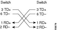
Figure C-5 and Figure C-6 show the schematics of two twisted-pair cables for connecting to 10BASE-T- and 100BASE-TX-compatible devices.
Figure C-5 Two Twisted-Pair Straight-Through Cable Schematic
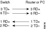
Figure C-6 Two Twisted-Pair Crossover Cable Schematic
Four Twisted-Pair Cable Pinouts for 1000BASE-T Ports
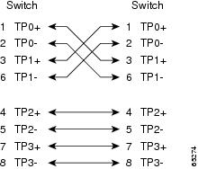
Figure C-7 and Figure C-8 show the schematics of four twisted-pair cables for 10/100/1000 ports on the Cisco IE 3000 switches.
Figure C-7 Four Twisted-Pair Straight-Through Cable Schematic for 10/100/1000 Ports
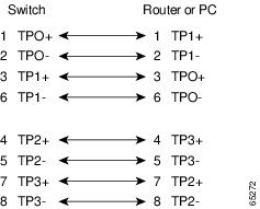
Figure C-8 Four Twisted-Pair Crossover Cable Schematics for 10/100/1000 Ports
Crossover Cable and Adapter Pinouts
This section describes how to identify a crossover cable and also describes the adapter pinouts.
Identifying a Crossover Cable
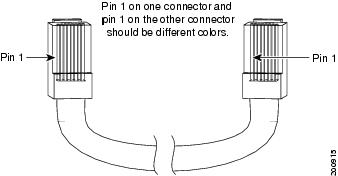
To identify a crossover cable, compare the two modular ends of the cable. Hold the cable ends side-by-side, with the tab at the back. The wire connected to the pin on the outside of the left plug should be a different color from the wire connected to the pin on the inside of the right plug. (See Figure C-9.)
Figure C-9 Identifying a Crossover Cable
Adapter Pinouts
Table C-2 lists the pinouts for the console port, the RJ-45-to-DB-9 adapter cable, and the console device.
|
Console Port (DTE) |
Terminal Adapter |
Device |
|---|---|---|
|
|
|
|
Table C-3 lists the pinouts for the console port, RJ-45-to-DB-25 female DTE adapter, and the console device.
Note![]() The RJ-45-to-DB-25 female DTE adapter is not supplied with the switch. You can order a kit (part number ACS-DSBUASYN=) containing this adapter from Cisco.
The RJ-45-to-DB-25 female DTE adapter is not supplied with the switch. You can order a kit (part number ACS-DSBUASYN=) containing this adapter from Cisco.
|
Port (DTE) |
Terminal A dapter |
Device |
|---|---|---|
|
|
|
|
 Feedback