Switch Models
|
Switch Model |
Description |
|---|---|
|
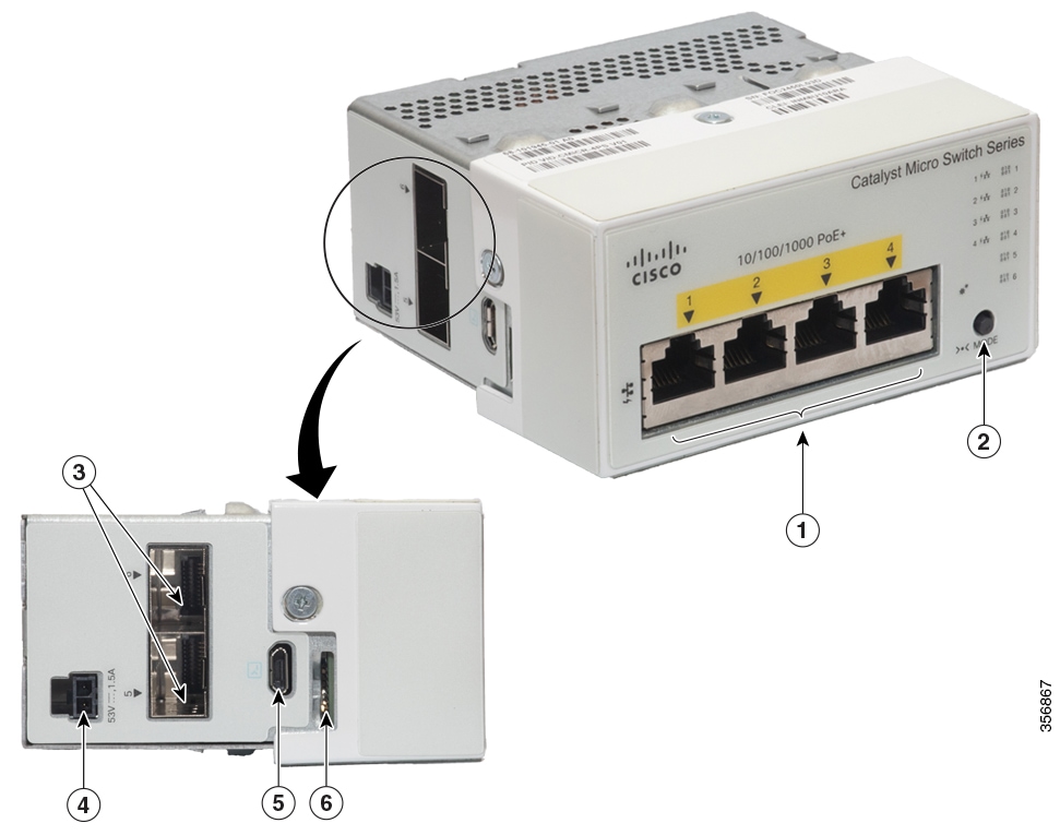
CMICR-4PS |
Four 1 Gigabit Ethernet downlink PoE+ ports; two 1 Gigabit Ethernet SFP uplink ports; uses external AC/DC adapters for power sourcing. |
|
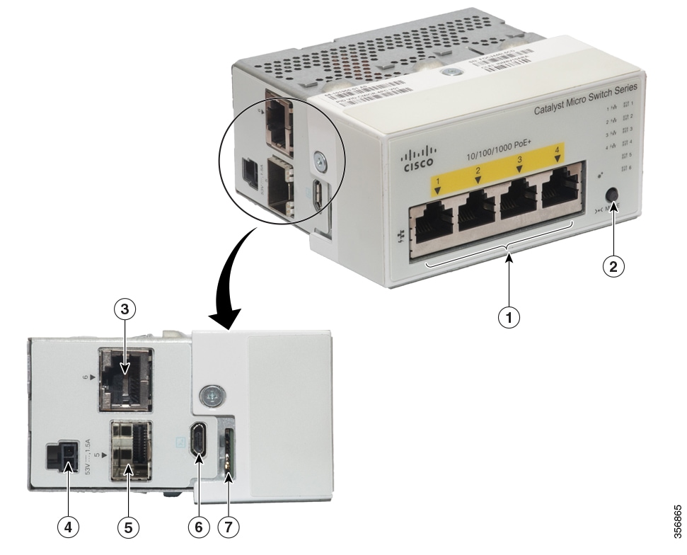
CMICR-4PC |
Four 1 Gigabit Ethernet downlink PoE+ ports; one 1 Gigabit Ethernet SFP and one 1 Gigabit Ethernet RJ-45 uplink ports; uses external AC/DC adapters for power sourcing. |
|
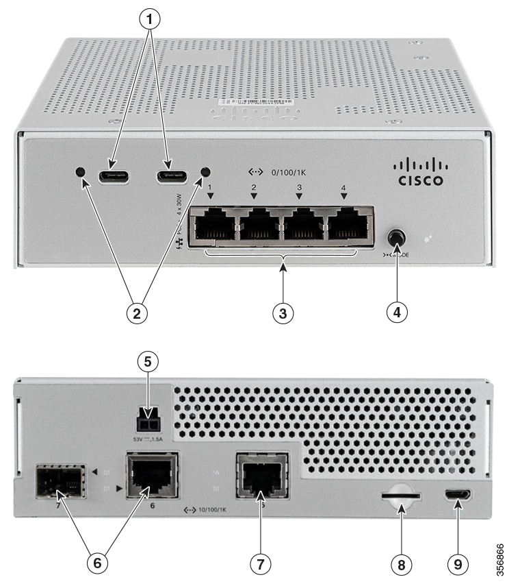
CMICR-4PT |
Four 1 Gigabit Ethernet downlink PoE+ ports; one 1 Gigabit Ethernet RJ-45 uplink port and one 1 Gigabit Ethernet RJ-45 or SFP combo uplink ports; two USB-C connectors for power sourcing; uses external AC/DC adapters or external PSE through PD ports for power sourcing. |


 Feedback