Restrictions for MPLS Layer 2 VPN over GRE
This feature is not supported on Cisco Catalyst 9600 Series Supervisor 2 Module (C9600X-SUP-2)
The documentation set for this product strives to use bias-free language. For the purposes of this documentation set, bias-free is defined as language that does not imply discrimination based on age, disability, gender, racial identity, ethnic identity, sexual orientation, socioeconomic status, and intersectionality. Exceptions may be present in the documentation due to language that is hardcoded in the user interfaces of the product software, language used based on RFP documentation, or language that is used by a referenced third-party product. Learn more about how Cisco is using Inclusive Language.
This feature is not supported on Cisco Catalyst 9600 Series Supervisor 2 Module (C9600X-SUP-2)
The MPLS Layer 2 VPN over GRE feature provides a mechanism for tunneling Multiprotocol Label Switching (MPLS) packets over non-MPLS networks. This feature allows you to create a generic routing encapsulation (GRE) tunnel across a non-MPLS network. The MPLS packets are encapsulated within the GRE tunnel packets, and the encapsulated packets traverse the non-MPLS network through the GRE tunnel. When GRE tunnel packets are received at the other side of the non-MPLS network, the GRE tunnel packet header is removed and the inner MPLS packet is forwarded to its final destination.
To configure MPLS Layer 2 VPN over GRE, you must have configured either Virtual Private LAN Service (VPLS) or EoMPLS (Ethernet over MPLS).
The following sections provide information about the different types of tunneling configurations that are supported.
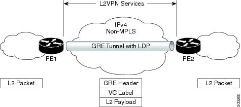
The provider edge-to-provider edge (PE-to-PE) tunneling configuration provides a scalable way to connect multiple customer networks across a non-MPLS network. With this configuration, traffic that is destined to multiple customer networks is multiplexed through a single GRE tunnel.
The PE device on one side of the non-MPLS network uses the routing protocols (that operate within the non-MPLS network) to learn about the PE device on the other side of the non-MPLS network. The learned routes that are established between the PE devices are then stored in the main or default routing table.
The opposing PE device uses Border Gateway Protocol (BGP) to learn about the routes that are associated with the customer networks that are behind the PE devices. These learned routes are not known to the non-MPLS network.
PE-to-PE Tunneling shows an end-to-end IP core from one PE device to another through the GRE tunnel that spans the non-MPLS network.
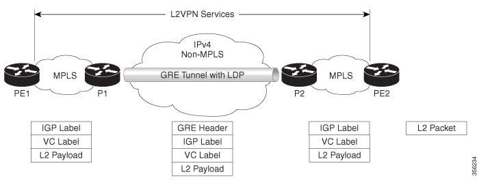
P-to-PE Tunneling shows a method of connecting two MPLS segments (P2 to PE2) across a non-MPLS network. In this configuration, MPLS traffic that is destined to the other side of the non-MPLS network is sent through a single GRE tunnel.

P-to-P Tunneling shows a method of connecting two MPLS segments (P1 to P2) across a non-MPLS network. In this configuration, MPLS traffic that is destined to the other side of the non-MPLS network is sent through a single GRE tunnel.
To configure the MPLS over GRE feature, you must create a GRE tunnel to span the non-MPLS networks. Perform the following procedure on the devices that are located at both ends of the GRE tunnel.
| Command or Action | Purpose | |
|---|---|---|
|
Step 1 |
enable Example: |
Enables privileged EXEC mode. Enter your password, if prompted. |
|
Step 2 |
configure terminal Example: |
Enters global configuration mode. |
|
Step 3 |
interface tunnel tunnel-number Example: |
Creates a tunnel interface and enters interface configuration mode. |
|
Step 4 |
ip address ip-address mask Example: |
Assigns an IP address to the tunnel interface. |
|
Step 5 |
tunnel source source-address Example: |
Configures the tunnel’s source IP address. |
|
Step 6 |
tunnel destination destination-address Example: |
Configures the tunnel’s destination IP address. |
|
Step 7 |
mpls ip Example: |
Enables MPLS on the tunnel’s physical interface. |
|
Step 8 |
end Example: |
Returns to privileged EXEC mode. |
The following section provides an example for configuring MPLS Layer 2 VPN over GRE.
The following examples show how to configure a generic GRE tunnel configuration that spans a non-MPLS network.
The following example shows the tunnel configuration on the PE1 device:
Device> enable
Device# configure terminal
Device(config)# interface Tunnel 1
Device(config-if)# ip address 10.1.1.1 255.255.255.0
Device(config-if)# tunnel source 10.0.0.1
Device(config-if)# tunnel destination 10.0.0.2
Device(config-if)# ip ospf 1 area 0
Device(config-if)# mpls ip
The following example shows the tunnel configuration on the PE2 device:
Device> enable
Device# configure terminal
Device(config)# interface Tunnel 1
Device(config-if)# ip address 10.1.1.2 255.255.255.0
Device(config-if)# tunnel source 10.0.0.2
Device(config-if)# tunnel destination 10.0.0.1
Device(config-if)# ip ospf 1 area 0
Device(config-if)# mpls ip
| Related Topic | Document Title |
|---|---|
|
Configuring VPLS |
For more information, see Information About VPLS. |
|
Configuring Ethernet-over-MPLS (EoMPLS) and Pseudowire Redundancy (PWR) |
For more information, see How to Configure Ethernet Over MPLS. |
This table provides release and related information for the features explained in this module.
These features are available in all the releases subsequent to the one they were introduced in, unless noted otherwise.
|
Release |
Feature |
Feature Information |
|---|---|---|
|
Cisco IOS XE Gibraltar 16.12.1 |
MPLS Layer 2 VPN over GRE |
The MPLS Layer 2 VPN over GRE feature provides a mechanism for tunneling MPLS packets over non-MPLS networks. |
Use the Cisco Feature Navigator to find information about platform and software image support. To access Cisco Feature Navigator, go to https://cfnng.cisco.com/
 Feedback