Installing a Switch

For initial switch setup, assigning the switch IP address, and powering on information, see the switch getting started guide on Cisco.com.

This chapter contains these topics:

Installation Tasks

After you prepare your site for installation, follow these tasks to install the switch:

Task

Description

Unpacking the switch

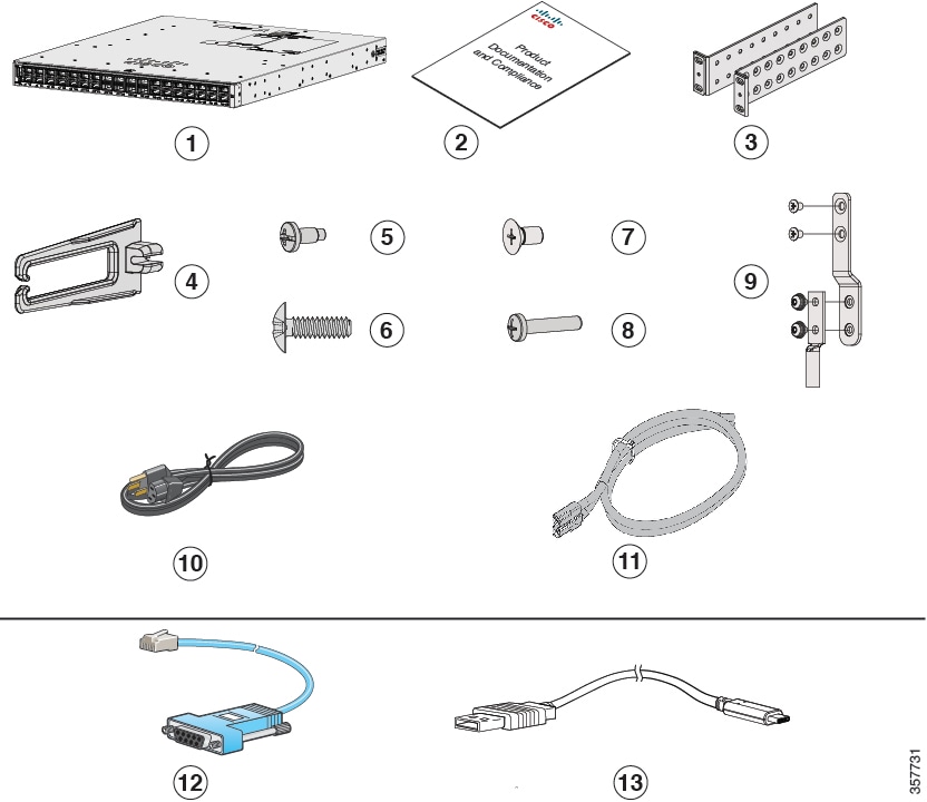
Remove the switch from the packaging material.
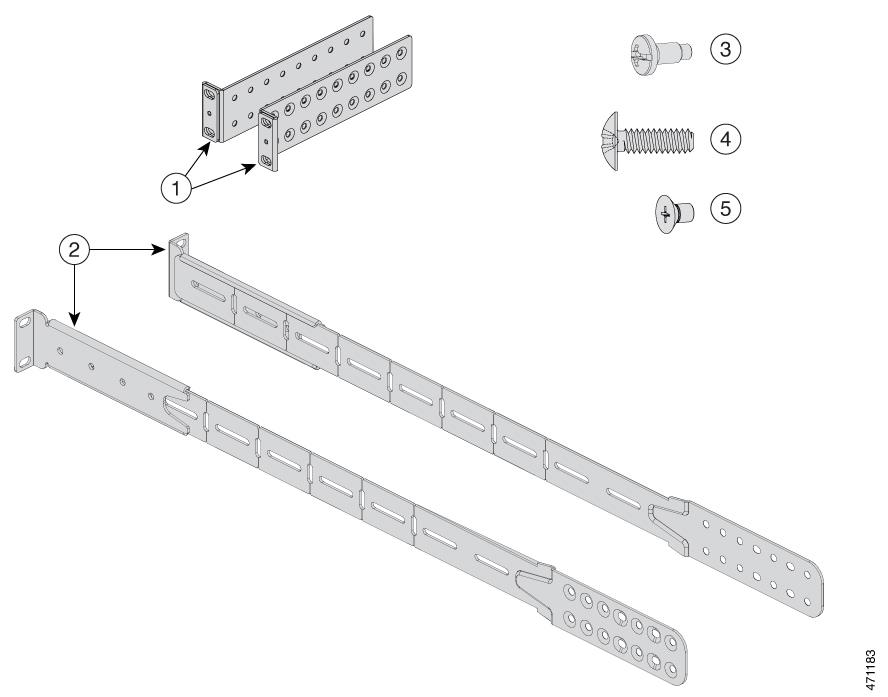
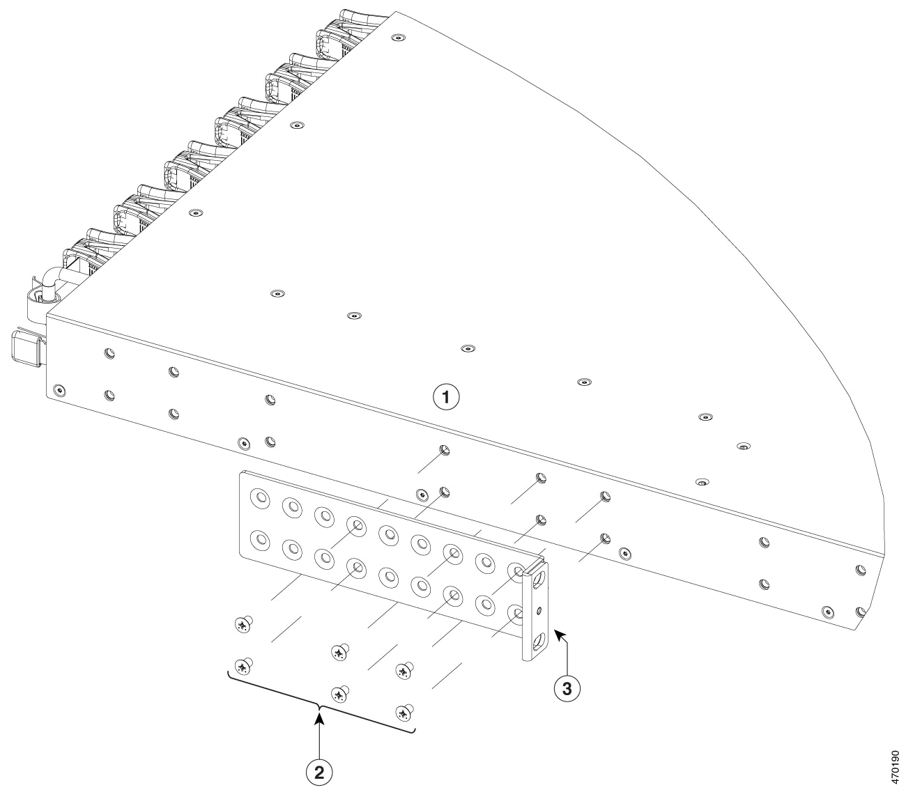
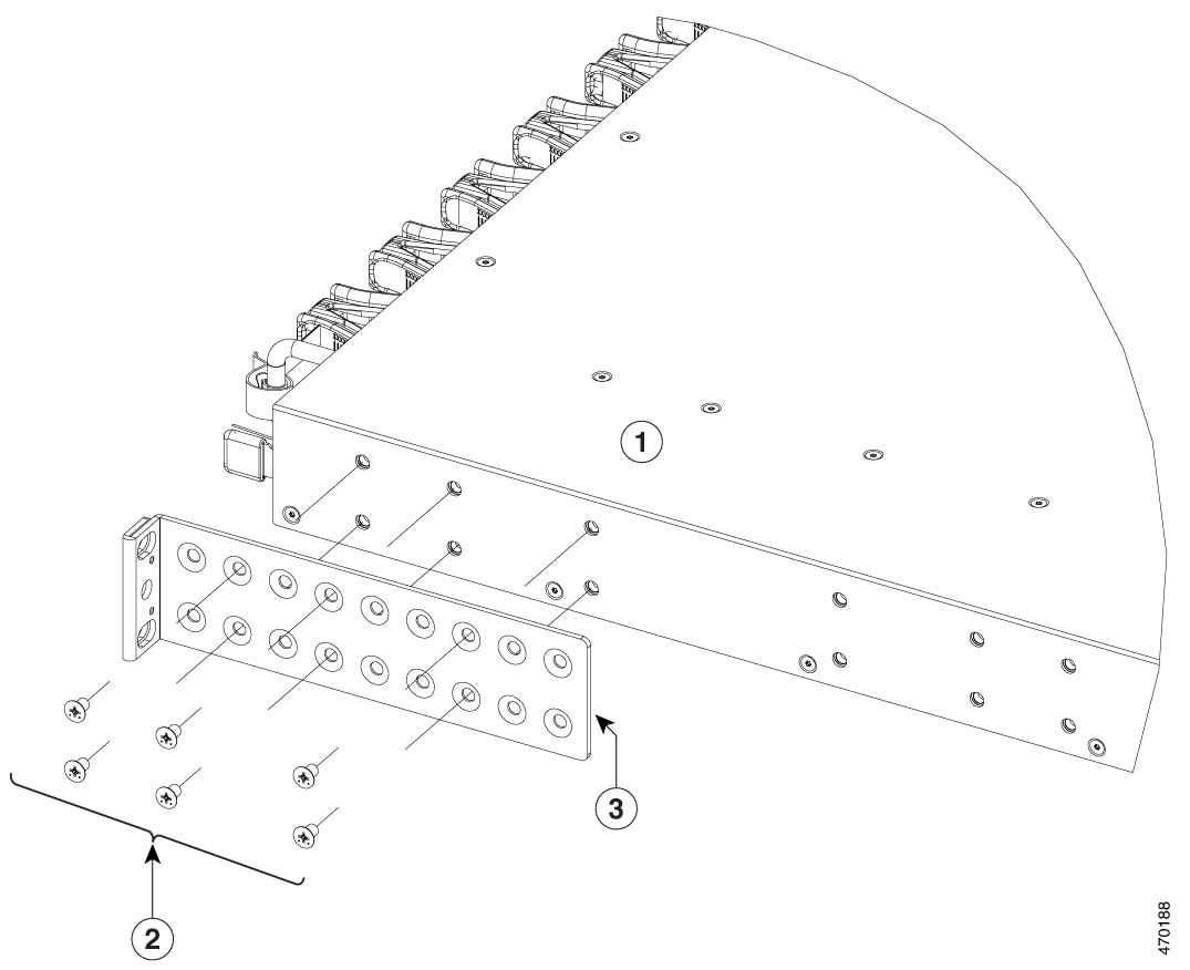
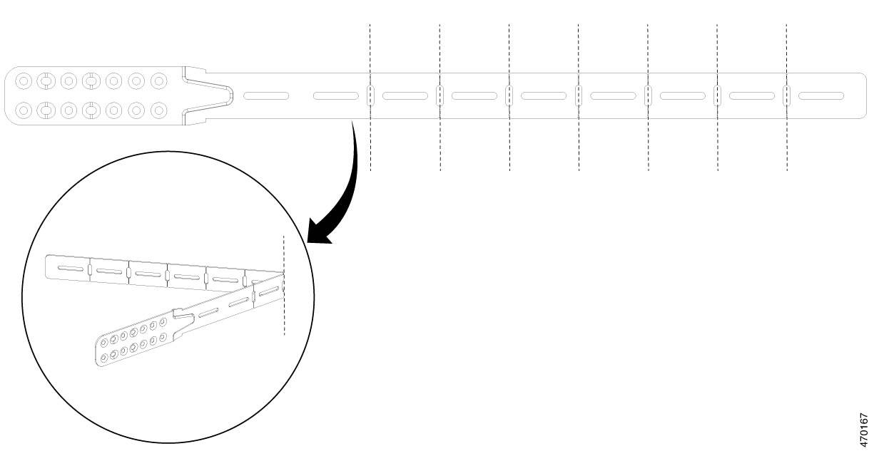
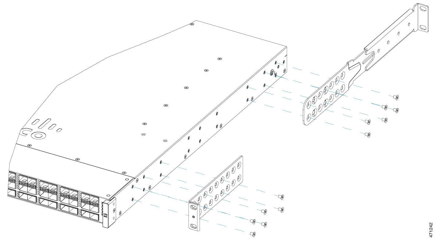
Note


Save the packaging material for later use if you need to move the chassis.

Installing the switch

Install the switch.

Connecting the chassis to system ground

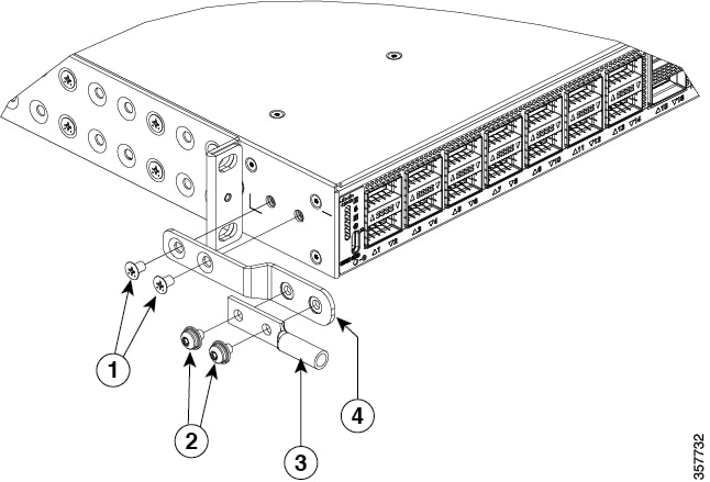
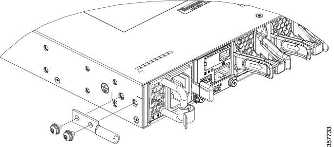
Construct and attach a system ground wire from the building (earth) ground to the system ground point on the chassis.

Installing the power supply module

Power supplies that are ordered with the switch are preinstalled in the switch. If ordered separately, install the power supplies.

Installing the fan

Install the fan modules in the fan module slots.

Cabling the chassis and modules to the network

The various ports on the chassis must be connected to the network. This process can involve only attaching a network interface cable to the port or it can include the installation of a transceiver of some type in port and then attaching the network interface cable to the transceiver.

Powering up the chassis

After completing the network cabling and making sure that system ground is connected, the power supplies can be turned on. The system powers up and runs through a set of built-in diagnostics.

Contents of the Shipping Box

The shipping box contains the model of the switch you ordered and other components needed for installation. Some components are optional, depending on your order.

Figure 1. Components Delivered in the Shipping Box of Cisco Catalyst 9500X Series Switches

1

Cisco Catalyst 9500X Series switch (power supply and fan modules not shown)

8

One M4.0 x 20mm Phillips pan-head screw (Black color)

2

Product documentation and compliance document

9

Ground lug and four M4.0 x 6mm screws (two pan-head and two flat-head screws)

3

Two 19-inch mounting brackets

10

(Optional) AC power cord 2

4

Cable guide

11

(Optional) DC power cord1

5

Four number-12 Phillips pan-head 0.50" long screws

12

(Optional) RJ-45 console cable1

6

Four number-10 Phillips pan-head 0.625" long screws

13

(Optional) USB console cable 1

7

12 M4.0 x 6mm Phillips flat-head screws

-

-


Note


  1. The item is orderable.

  2. The item is orderable. You can choose the type of AC cord as per your requirement.


Spare Accessory Kits

The following table describes the spare accessory kits supported on different switch models:

Table 1. Spare Accessory Kits and Rack Mount Kits for Cisco Catalyst 9500X Series Switches

Part Number

Description

Switches Supported

C9500X-ACCKIT-19I=

19" rack mount accessory kit for Cisco Catalyst 9500X Series switches.

C9500X-28C8D

C9500X-60L4D

C9500X-ACCKIT-23I=

23" rack mount accessory kit for Cisco Catalyst 9500X Series switches.

C9500X-4PTH-KIT=

Extension rails and brackets for four-point mounting for Cisco Catalyst 9500X Series switches.

Unpacking the Switch


Note


Do not discard the shipping container when you unpack the switch. Flatten the shipping cartons and store them with the pallet. You will need these containers if you need to move or ship the switch in the future.


Check the contents of the accessory kit. Verify that you received all listed equipment, which should include the following:

  • Grounding lug and disposable ESD strap.
  • Optional equipment that you ordered, such as console cables, transceivers, or special connectors.

  • Blank covers are installed for the power supply slots on the chassis.

Establishing the System Ground

This section describes how to connect a system ground to the switch.


Caution


Installations that rely solely on system grounding using only an AC third-prong ground run a substantially greater risk of equipment problems and data corruption than those installations that use both the AC third-prong ground and a properly installed system ground.

The system ground provides additional grounding for EMI shielding requirements and grounding for the low voltage supplies (DC-DC converters) on the modules. You must observe the following system grounding guidelines for your chassis:

  • You must install the system ground connection with any other rack or system power ground connections that you make. The system ground connection is required if FXS modules are installed or if this equipment is installed in a U.S. or European Central Office.

  • You must connect both the system ground connection and the power supply ground connection to an earth ground. The system ground connection is required if FXS modules are installed or if this equipment is installed in a U.S. or European Central Office.

  • When using DC-input power supplies, you must install the system ground before you attach the source DC power cables to the DC PEM. Power down the chassis before attaching the system ground.


Note


In all situations, grounding practices must comply with Section 250 of the National Electric Code (NEC) requirements or local laws and regulations. A 6 AWG grounding wire is recommended from the chassis to the rack ground or directly to the common bonding network (CBN). The equipment rack should also be connected to the CBN with 6 AWG grounding wire.

Note


The system ground serves as the primary safety ground for chassis that are equipped with DC-input power supplies. The DC-input power supplies for these chassis do not have a separate ground.


Required Tools and Equipment

To connect the system ground, you need the following tools and materials:

  • Grounding lug — When using the double-hole lug connector provided with the system, the ground wire must be 6 AWG only. Otherwise, a supported closed-loop ring connector must be used for 8-14 AWG wire.

  • Grounding screws — Two M4.0 x 6mm Phillips pan-head screws. Supplied as part of the accessory kit.

  • Grounding wire — Not supplied as part of accessory kit. The grounding wire should be sized according to local and national installation requirements. For U.S. installations, AC power supply systems require a 14 AWG copper conductor. Commercially available 8-14 AWG wire is recommended. DC power supply systems with 930W power supply module require a 12 AWG wire and 1500W power supply module require a 8 AWG wire. The length of the grounding wire depends on the proximity of the switch to proper grounding facilities.

  • No. 1 Phillips screwdriver.

  • Crimping tool to crimp the grounding wire to the grounding lug.

  • Wire-stripping tool to remove the insulation from the grounding wire.

Connecting the System Ground

To establish an earth ground for the chassis, you must attach a grounding cable from the chassis’ grounding lug to the rack.

Procedure


Step 1

Use a wire-stripping tool to remove approximately 0.75 inch (19 mm) of the covering from the end of the grounding wire.

Step 2

Insert the stripped end of the grounding wire into the open end of the grounding lug.

Step 3

Crimp the grounding wire in the barrel of the grounding lug. Verify that the ground wire is securely attached to the ground lug.

Step 4

Place the grounding wire lug against the grounding pad on the switch, making sure that there is solid metal-to-metal contact.

You can install the grounding lug on the left or the right side of the chassis; the grounding pad on C9500X switches are located on the sides of the chassis.

Step 5

Before you secure the lug to the chassis, make sure that the grounding lug and the grounding wire do not interfere with other switch hardware or rack equipment. Secure the grounding bracket and the lug to the chassis with two M4.0x 6mm flat-head screws.

Figure 2. Installing the Grounding Lug on a C9500X Switch


1

M4.0 x 6mm flat-head screws

3

Grounding lug

2

M4.0 x 6mm pan-head screws

4

Grounding bracket

Note


In situations where there is no interference with the rack, other switch hardware or rack equipment, you can install the lug directly on to the chassis without the grounding bracket.

Figure 3. Installing the Lug Without Grounding Bracket


Step 6

Prepare the other end of the grounding wire with a ring lug, and secure it to the rack with a screw.


Installing the Switch

Rack-Mounting

  • For Network Equipment Building Systems (NEBS) installation, use the four post rack mount kit. The depth of the rack, measured between the front-mounting and the rear-mounting strips must be between 24.72 inches and 39.75 inches.

  • Ensure you read the Regulatory Compliance and Safety Information (RCSI) before installing the switch.

  • Installation in racks other than 19-inch racks requires a bracket kit not included with the switch.


Warning


To prevent bodily injury when mounting or servicing this unit in a rack, you must take special precautions to ensure that the system remains stable. The following guidelines are provided to ensure your safety:

  • This unit should be mounted at the bottom of the rack if it is the only unit in the rack.

  • When mounting this unit in a partially filled rack, load the rack from the bottom to the top with the heaviest component at the bottom of the rack.


Warning


Statement 1006—Chassis Warning for Rack-Mounting and Servicing

To prevent bodily injury when mounting or servicing this unit in a rack, you must take special precautions to ensure that the system remains stable. The following guidelines are provided to ensure your safety:

  • This unit should be mounted at the bottom of the rack if it is the only unit in the rack.

  • When mounting this unit in a partially filled rack, load the rack from the bottom to the top with the heaviest component at the bottom of the rack.

  • If the rack is provided with stabilizing devices, install the stabilizers before mounting or servicing the unit in the rack.


Figure 4. Four Post Rack Mount Kit for Cisco Catalyst 9500X Series Switches. This figure shows the four post rack mount kit for Cisco Catalyst 9500X Series Switches. You can order the optional brackets from your Cisco sales representative.

Rack Mount kit for 9500X series switches

1

Two 19-inch brackets

4

Eight number-10 Phillips pan-head 0.625" long screws

2

Extension rails and brackets for four-point mounting

5

24 M4.0 x 6mm Phillips flat-head screws

3

Eight number-12 Phillips pan-head 0.50" long screws

-

-

Figure 5. 23-inch Rack Mount Kit for Cisco Catalyst 9500X Series Switches. This figure shows the optional 23-inch rack mount kit for Cisco Catalyst 9500X Series Switches. You can order the kit from your Cisco sales representative.


1

23-inch rack mount bracket

Attaching the Rack-Mount Brackets

Before you begin

Determine which end of the switch should be located in the cold aisle of the site:

  • If the switch supports front-to-back air flow (C9500X-FAN-1U-R fan module), position the switch such that ports are located in the cold aisle.

    Switch position for front-to-back-air flow
  • If the switch supports back-to-front air flow (C9500X-FAN-1U-F fan module), position the switch such that the fan and power supply modules are located in the cold aisle.

    Switch position for back-to-front-air flow
Procedure

Step 1

Attach the rack-mount brackets to the switch.

Use M4.0x6mm Phillips flat-head screws to attach the long side of the bracket to each side of the switch for the front, middle, or rear mounting positions.

Figure 6. Front Mounting position of Rack Mounting Brackets. Cisco Catalyst 9500X Series Switches use 6 screws to install the bracket on one side of the switch.
Figure 7. Middle Mounting position of Rack Mounting Brackets
Figure 8. Rear Mounting position of Rack Mounting Brackets

1

Cisco Catalyst 9500X Series switch

3

19-inch mounting brackets

2

M4.0x6mm Phillips flat-head screws

-

-

Step 2

The extension rail that is provided may be longer than the required size. To trim the extension rail to the required length, bend the extension rail along the mark specified and cut it.

Figure 9. Bend and Cut the Extension Rail to the Required Length

Step 3

  1. If the switch ports are located in the cold aisle (front-to-back air flow), use the Phillips machine screws to attach the brackets and the extension rail to the switch.

    Figure 10. Attaching the Extension Rail. Use six screws to attach the extension rail on to one side of the switch.
    attach the extendion rail
  2. If the switch ports are located away from the cold aisle (back-to-front air flow):

    1. First disassemble the RFID as shown.

      Disassemble RFID
    2. Use the Phillips machine screws to attach the brackets and the extension rail to the switch.

      attach the brackets and extension rail to the switch

Mounting the Switch in a Rack

Procedure

Step 1

Use the black Phillips machine screw to attach the cable guide to the left or right bracket.

Figure 11. Attaching the Cable Guide


1

19-inch bracket

3

Cable guide

2

Phillips machine screws

4

M4.0x20mm Phillips pan-head screws (Black color)

Step 2

Secure the switch to the rack rails using the Number-12 or number-10 Phillips machine screws provided with the accessory kit.

Figure 12. Mounting the Switch in a Rack


1

Cisco Catalyst 9500X Series switch front-mounting position

2

Number-12 or number-10 Phillips machine screws


After Switch Installation

  • Configure the switch using the Web User Interface. For more information, see "Configuring the Switch Using the Web User Interface" topic in the Software Configuration Guide.

  • Connect the required devices to the switch ports.

  • Turn on the power supply switches to power up the system. While powering up, the switch performs a series of bootup diagnostic tests.


    Note


    The switch is designed to boot up in less than 30 minutes, provided that the neighboring devices are in fully operational state.


  • Verify port connectivity after connecting devices to the switch ports. The LED turns green when the switch and the attached device have a link.