Switch Models
|
Switch Model |
Description |
|---|---|
|
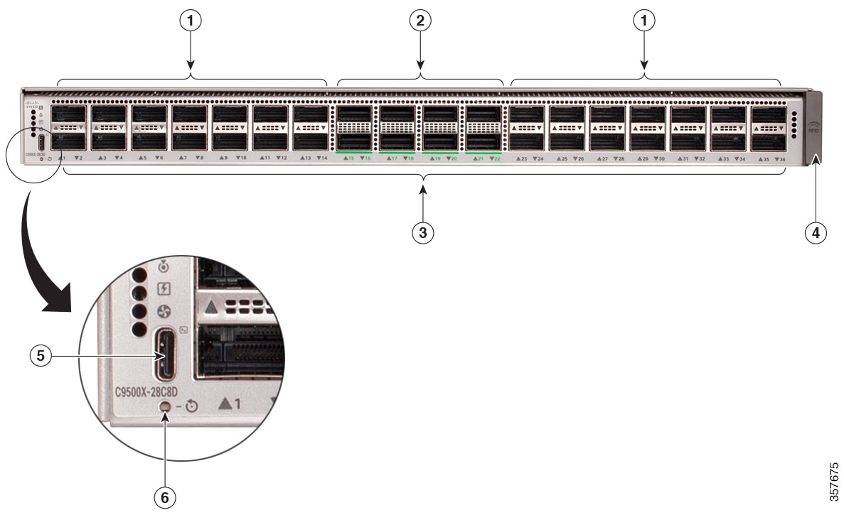
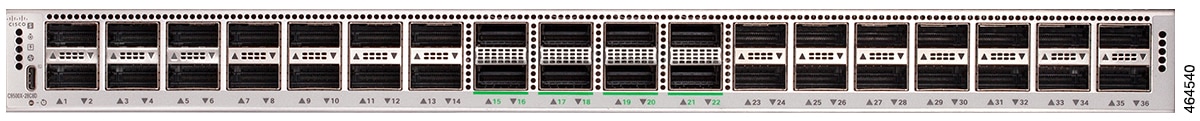
C9500X-28C8D |
28x100G QSFP28 and 8x400G QSFP-DD ports; 2 power supply slots |
|
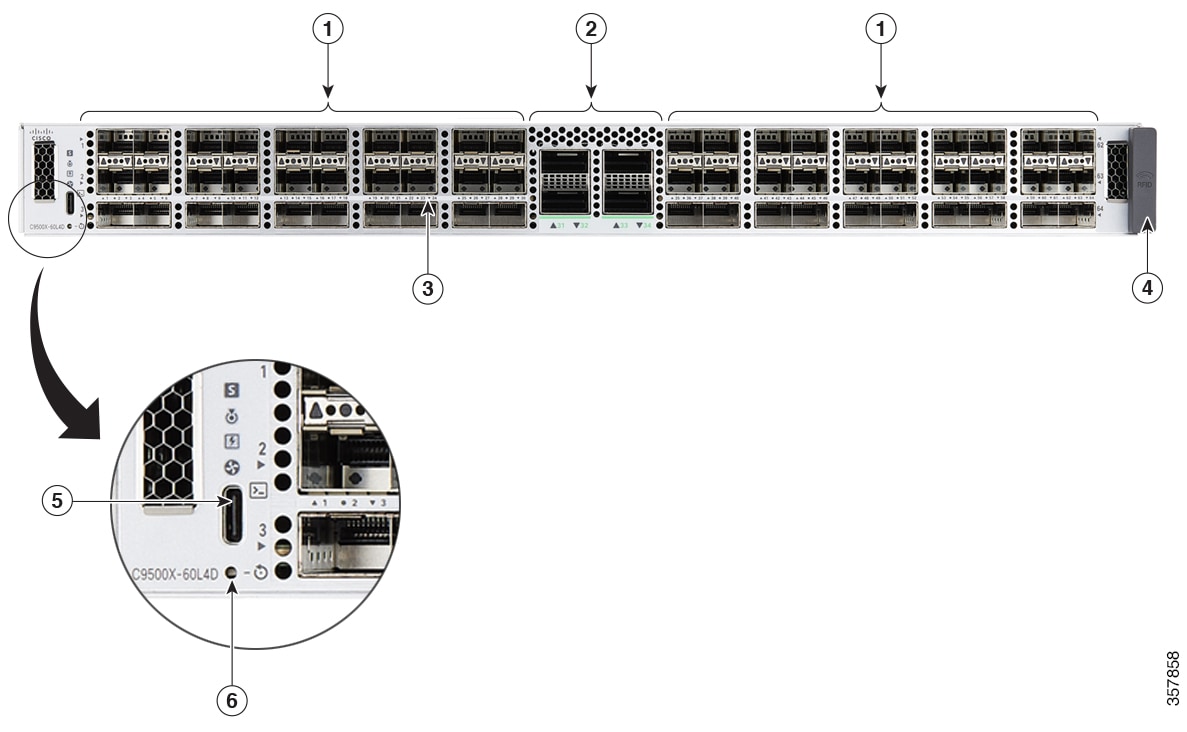
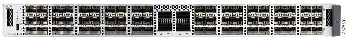
C9500X-60L4D |
60x50G SFP56 and 4x400G QSFP-DD ports; 2 power supply slots 1 |

 Feedback