Preparing for
Installation
- Safety Warnings
- Preventing Electrostatic Discharge Damage
- Establishing System Ground
- Attaching an ESD Strap
- Tools Required for Module Installation or Removal
Safety Warnings
Safety warnings appear throughout this publication in procedures that may harm you if you perform them incorrectly. A warning symbol precedes each warning statement. The warnings below are general warnings that are applicable to the entire publication.
 Warning | Class 1 laser product. Statement 1008 |
Warning | Read the installation instructions before connecting the system to the power source. Statement 1004 |
Warning | Only trained and qualified personnel should be allowed to install, replace, or service this equipment. Statement 1030 |
Warning | Before opening the unit, disconnect the telephone-network cables to avoid contact with telephone-network voltages. Statement 1041 |
Warning | During this procedure, wear grounding wrist straps to avoid ESD damage to the card. Do not directly touch the backplane with your hand or any metal tool, or you could shock yourself. Statement 94 |
Warning | Invisible laser radiation may be emitted from disconnected fibers or connectors. Do not stare into beams or view directly with optical instruments. Statement 1051 |
Preventing Electrostatic Discharge Damage
Electrostatic discharge (ESD) damage may occur when modules or other FRUs are improperly handled, and result in intermittent or complete failure of the modules or FRUs. Modules consist of printed circuit boards that are fixed in metal carriers. EMI shielding and connectors are integral components of a carrier. Although the metal carrier helps to protect the board from ESD, always use an ESD-grounding strap when handling modules. To prevent ESD damage, follow these guidelines:
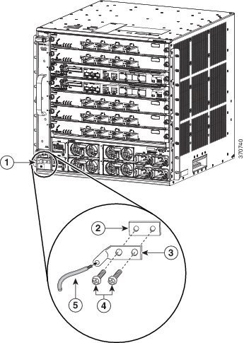
Establishing System Ground
To attach the grounding lug and cable to the grounding pad, perform these steps
To connect the system ground, you require the following tools and materials:
-
Grounding lug—A two-hole right-angled lug. Supports up to 6 AWG wire. Supplied as part of accessory kit.
-
Grounding screws—Two M4 x 8 mm (metric) pan-head screws. Supplied as part of the accessory kit.
-
Grounding wire—Not supplied as part of accessory kit. The grounding wire should be sized according to local and national installation requirements. Depending on the power supply and system, a 12 to 6 AWG copper conductor is required for U.S. installations. Commercially available 6-AWG wire is recommended. The length of the grounding wire depends on the proximity of the switch to proper grounding facilities.
-
No. 1 Phillips screwdriver.
-
Crimping tool to crimp the grounding wire to the grounding lug.
-
Wire-stripping tool to remove the insulation from the grounding wire.
1. Use a wire-stripping tool to remove approximately 0.75 inches (19 mm) of the covering from the end of the grounding wire.
2. Insert the stripped end of the grounding wire into the open end of the right-angled grounding lug.
3. Crimp the grounding wire in the barrel of the grounding lug. Verify that the ground wire is securely attached to the ground lug.
4. Secure the grounding lug to the system ground connector with two M4 screws. Ensure that the grounding lug and the grounding wire do not interfere with other switch hardware or rack equipment.
5. Prepare the other end of the grounding wire, and connect it to an appropriate grounding point in your site to ensure adequate earth ground for the switch.
DETAILED STEPS
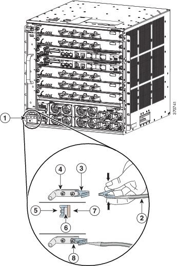
Attaching an ESD Strap
After you install the system ground lug, follow these steps to correctly attach the ESD wrist strap:
1. Attach the ESD wrist strap to bare skin as follows:
2. Grasp the spring or alligator clip on the ESD wrist strap and momentarily touch the clip to a bare metal spot (unpainted surface) on the rack. We recommend that you touch the clip to an unpainted rack rail so that any built-up static charge is then safely dissipated to the entire rack.
3. Attach either the spring clip or the alligator clip to the ground lug screw as follows:
DETAILED STEPS
| Step 1 | Attach the ESD
wrist strap to bare skin as follows:
| ||||||||||||||||||
| Step 2 | Grasp the spring or alligator clip on the ESD wrist strap and momentarily touch the clip to a bare metal spot (unpainted surface) on the rack. We recommend that you touch the clip to an unpainted rack rail so that any built-up static charge is then safely dissipated to the entire rack. | ||||||||||||||||||
| Step 3 | Attach either
the spring clip or the alligator clip to the ground lug screw as follows:
|
 Feedback