Port, Cable, and Connector Specifications
This appendix lists the port, cable, and connector specifications for the Catalyst 6500 series supervisor engines. The following ports, cables, and connectors along with signal summaries are contained in this appendix:
•![]() Copper and Fiber-Optic Connectors
Copper and Fiber-Optic Connectors
Also included in this appendix is information and procedures on how to clean the fiber-optic connectors.
Console Port
The console port allows you to access the switch either locally (through a console terminal) or remotely (through a modem). The console port is an EIA/TIA-232 asynchronous, serial connection with hardware flow control and an RJ-45 connector. This section covers the following topics:
•![]() Console Port Cables and Adapters
Console Port Cables and Adapters
•![]() CONSOLE PORT MODE Switch (Supervisor Engine 2 Only)
CONSOLE PORT MODE Switch (Supervisor Engine 2 Only)
Console Port Cables and Adapters
The Catalyst 6500 series switch comes with an accessory kit that contains the cable and adapters you need to connect a console (an ASCII terminal or PC running terminal emulation software) or modem to the supervisor engine console port. The accessory kit includes the following items:
•![]() RJ-45-to-RJ-45 rollover cable
RJ-45-to-RJ-45 rollover cable
•![]() RJ-45-to-DB-9 female DTE adapter (labeled "Terminal")
RJ-45-to-DB-9 female DTE adapter (labeled "Terminal")
•![]() RJ-45-to-DB-25 female DTE adapter (labeled "Terminal")
RJ-45-to-DB-25 female DTE adapter (labeled "Terminal")
•![]() RJ-45-to-DB-25 male DCE adapter (labeled "Modem")
RJ-45-to-DB-25 male DCE adapter (labeled "Modem")

Note ![]() This is the same rollover cable and connector adapters that ship with many other Cisco products.
This is the same rollover cable and connector adapters that ship with many other Cisco products.
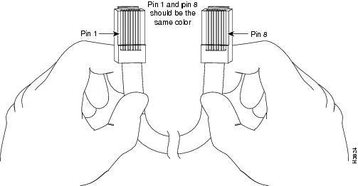
You can identify a rollover cable by comparing the two ends of the cable. Holding the cables side-by-side, with the tab at the back, the wire connected to the pin on the outside of the left plug should be the same color as the wire connected to the pin on the outside of the right plug. (See Figure B-1.) If your cable was purchased from Cisco Systems, pin 1 will be white on one connector, and pin 8 will be white on the other (a rollover cable reverses pins 1 and 8, 2 and 7, 3 and 6, and 4 and 5).
Figure B-1 Identifying a Rollover Cable
CONSOLE PORT MODE Switch (Supervisor Engine 2 Only)
The supervisor engine front-panel CONSOLE PORT MODE switch, only on the Supervisor Engine 2, allows you to connect a terminal or modem to the console port as follows:
•![]() Mode 1—Switch in the in position. Use this mode to connect a terminal to the console port using the RJ-45-to-RJ-45 rollover cable and DTE adapter (labeled "Terminal").
Mode 1—Switch in the in position. Use this mode to connect a terminal to the console port using the RJ-45-to-RJ-45 rollover cable and DTE adapter (labeled "Terminal").
You can also use this mode to connect a modem to the console port using the RJ-45-to-RJ-45 rollover cable and DCE adapter (labeled "Modem").
•![]() Mode 2—Switch in the out position. Use this mode to connect a terminal to the console port using the Catalyst 5000 family Supervisor Engine III console cable and appropriate adapter for the terminal connection (cable and adapter are not provided).
Mode 2—Switch in the out position. Use this mode to connect a terminal to the console port using the Catalyst 5000 family Supervisor Engine III console cable and appropriate adapter for the terminal connection (cable and adapter are not provided).
Note ![]() Use a ballpoint pen tip or other small, pointed object to access the CONSOLE PORT MODE switch. The switch is shipped in the in position.
Use a ballpoint pen tip or other small, pointed object to access the CONSOLE PORT MODE switch. The switch is shipped in the in position.
Console Port Mode 1 Signaling and Pinouts
This section provides the signaling and pinouts for the console port in mode 1 (CONSOLE PORT MODE switch in the in position).
DB-9 Adapter (for Connecting to a PC)
Use the RJ-45-to-RJ-45 rollover cable and RJ-45-to-DB-9 female DTE adapter (labeled "Terminal") to connect the console port to a PC running terminal emulation software. Table B-1 lists the pinouts for the asynchronous serial console port, the RJ-45-to-RJ-45 rollover cable, and the RJ-45-to-DB-9 female DTE adapter.
|
|
|
|
|
|
|---|---|---|---|---|
|
|
|
|
|
|
RTS |
11 |
8 |
8 |
CTS |
DTR |
2 |
7 |
6 |
DSR |
TxD |
3 |
6 |
2 |
RxD |
GND |
4 |
5 |
5 |
GND |
GND |
5 |
4 |
5 |
GND |
RxD |
6 |
3 |
3 |
TxD |
DSR |
7 |
2 |
4 |
DTR |
CTS |
81 |
1 |
7 |
RTS |
1 Pin 1 is connected internally to Pin 8. |
DB-25 Adapter (for Connecting to a Terminal)
Use the RJ-45-to-RJ-45 rollover cable and the RJ-45-to-DB-25 female DTE adapter (labeled "Terminal") to connect the console port to a terminal. Table B-2 lists the pinouts for the asynchronous serial console port, the RJ-45-to-RJ-45 rollover cable, and the RJ-45-to-DB-25 female DTE adapter.
|
|
|
|
|
|
|---|---|---|---|---|
|
|
|
|
|
|
RTS |
11 |
8 |
5 |
CTS |
DTR |
2 |
7 |
6 |
DSR |
TxD |
3 |
6 |
3 |
RxD |
GND |
4 |
5 |
7 |
GND |
GND |
5 |
4 |
7 |
GND |
RxD |
6 |
3 |
2 |
TxD |
DSR |
7 |
3 |
20 |
DTR |
CTS |
81 |
1 |
4 |
RTS |
1 Pin 1 is connected internally to Pin 8. |
Modem Adapter
Use the RJ-45-to-RJ-45 rollover cable and the RJ-45-to-DB-25 male DCE adapter (labeled "Modem") to connect the console port to a modem. Table B-3 lists the pinouts for the asynchronous serial auxiliary port, the RJ-45-to-RJ-45 rollover cable, and the RJ-45-to-DB-25 male DCE adapter.
|
|
|
|
|
|
|---|---|---|---|---|
|
|
|
|
|
|
RTS |
11 |
8 |
4 |
RTS |
DTR |
2 |
7 |
20 |
DTR |
TxD |
3 |
6 |
3 |
TxD |
GND |
4 |
5 |
7 |
GND |
GND |
5 |
4 |
7 |
GND |
RxD |
6 |
3 |
2 |
RxD |
DSR |
7 |
3 |
8 |
DCD |
CTS |
81 |
1 |
5 |
CTS |
1 Pin 1 is connected internally to Pin 8. |
Console Port Mode 2 Signaling and Pinouts
This section provides the signaling and pinouts for the console port in mode 2 (CONSOLE PORT MODE switch in the out position). See Table B-4 for the pinouts.
|
|
|
|---|---|
|
|
|
1 (RTS)1 |
Output |
2 (DTR) |
Output |
3 (RxD) |
Input |
4 (GND) |
GND |
5 (GND) |
GND |
6 (TxD) |
Output |
7 (DSR) |
Input |
8 (CTS)1 |
Input |
1 Pin 1 is connected internally to Pin 8. |
Uplink Ports
The Supervisor Engine 2, Supervisor Engine 32, Supervisor Engine 32 PISA, the Supervisor Engine 720, Supervisor Engine 720-10GE, and the Supervisor Engine 2T all have Ethernet uplink ports available on the front panel. These Ethernet ports can be used to provide additional port capacity for a fully configured switch or can reduce the need to use a chassis slot for a Gigabit Ethernet module or 10-Gigabit Ethernet module where only a few Gigabit or 10-Gigabit Ethernet ports are required. Table B-5 lists the supervisor engine model and the number and type of uplink ports available.
Three types of XENPAK and X2 transceivers have cabling guidelines. The transceivers types and their guidelines are listed in Table B-6.
USB Ports
Supervisor Engine 32, Supervisor Engine 32 PISA, Supervisor Engine 720-10GE, and Supervisor Engine 2T have two USB ports located on front panel. One port is designated for host use and the other as a device port. A host USB port can be used to plug in devices such as a PC, while device ports can be used for attaching Flash Memory Key devices.
Note ![]() Currently the two USB ports are not enabled on the Supervisor Engine 32, Supervisor Engine 32 PISA, and Supervisor Engine 720-10GE. The 5-pin USB port on the Supervisor Engine 2T is enabled. The second USB connector is not currently enabled.
Currently the two USB ports are not enabled on the Supervisor Engine 32, Supervisor Engine 32 PISA, and Supervisor Engine 720-10GE. The 5-pin USB port on the Supervisor Engine 2T is enabled. The second USB connector is not currently enabled.
Copper and Fiber-Optic Connectors
This section describes the types of copper and fiber-optic connectors that are used with the supervisor engines.
RJ-45 Connector
The RJ-45 connector (see Figure B-2) is used to connect a Category 3, Category 5, Category 5e, Category 6, or Category 6a FTP or UTP cable from the modem or terminal to the supervisor engine console port, or the network to a copper uplink port if the uplink port has a 1000BASE-T copper transceiver installed in it.

Figure B-2 RJ-45 Interface Cable Connector

Fiber-Optic Connectors
This section describes the SC and LC fiber-optic connectors used by the optical transceivers.
SC Connectors
 |
Warning |
The SC connector is used to connect fiber-optic module ports with the external network. (See Figure B-3.)
Figure B-3 SC Optical Connector

Always make sure that you insert the connector completely into the socket. This action is especially important when you are making a connection between a module and a long distance (1.24 miles [2 kilometers]) or a suspected highly attenuated network. If the link LED does not light, try removing the network cable plug and reinserting it firmly into the module socket. It is possible that enough dirt or skin oils have accumulated on the plug faceplate (around the optical-fiber openings) to generate significant attenuation, reducing the optical power levels below threshold levels so that a link cannot be made.
When you disconnect the fiber-optic cable from the module, grip the body of the connector. Do not grip the connector jacket-sleeve. Gripping the sleeve can, over time, compromise the integrity of the fiber-optic cable termination in the SC connector.
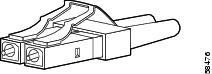
LC Connectors
Small form-factor pluggable (SFP) transceiver modules used on the Supervisor Engine 720 and Supervisor Engine 2T uplink ports use LC connectors shown in Figure B-4.
Figure B-4 LC Fiber-Optic Connector
When you disconnect the fiber-optic cable from the module, grip the body of the connector. Do not grip the connector jacket-sleeve. Gripping the sleeve can, over time, compromise the integrity of the fiber-optic cable termination in the LC connector.
|
Warning |
 Feedback