Catalyst 6500 Series Switch Module Installation Note
Available Languages
Table of Contents
Catalyst 6500 Series Switch Module Installation Note
Statement 1071—Warning Definition
Removing the Supervisor Engine or Module
Installing the Supervisor Engine or Module
Cabling the Supervisor Engine or Module
Verifying Newly Installed Modules
Regulatory Standards Compliance
Obtaining Documentation and Submitting a Service Request
Catalyst 6500 Series Switch Module Installation Note
This publication contains the procedures for installing Catalyst 6500 series modules in the Catalyst 6500 series switches and Cisco 7600 series routers. For procedures on installing Optical Services Modules (OSMs) in Catalyst 6500 series switches and Cisco 7600 series routers, refer to the Optical Services Module Installation and Verification Note. For additional information on individual modules, refer to the Catalyst 6500 Series Switch Module Installation Guide.

Note![]() In this publication, the term Catalyst 6500 series refers to both the Catalyst 6000 series switches (Catalyst 6006 and Catalyst 6009 switches) and the Catalyst 6500 series switches (Catalyst 6503, Catalyst 6506, Catalyst 6509, Catalyst 6509-NEB, Catalyst 6509-NEB-A, and Catalyst 6513 switches) unless otherwise noted.
In this publication, the term Catalyst 6500 series refers to both the Catalyst 6000 series switches (Catalyst 6006 and Catalyst 6009 switches) and the Catalyst 6500 series switches (Catalyst 6503, Catalyst 6506, Catalyst 6509, Catalyst 6509-NEB, Catalyst 6509-NEB-A, and Catalyst 6513 switches) unless otherwise noted.

Note![]() For the latest Catalyst 6500 series switch and Cisco 7600 series router software release notes, including caveats and updates, refer to the release notes for the latest maintenance release in your software release. You can access release notes at the World Wide Web locations listed in the “Obtaining Documentation” section.
For the latest Catalyst 6500 series switch and Cisco 7600 series router software release notes, including caveats and updates, refer to the release notes for the latest maintenance release in your software release. You can access release notes at the World Wide Web locations listed in the “Obtaining Documentation” section.
Overview
Table 1 lists the Catalyst 6500 series switches and the Cisco 7600 series routers.

Note![]() Throughout this publication, except where noted, the term supervisor engine refers to Supervisor Engine 1, Supervisor Engine 2, and Supervisor Engine 720.
Throughout this publication, except where noted, the term supervisor engine refers to Supervisor Engine 1, Supervisor Engine 2, and Supervisor Engine 720.

Note![]() Specific combinations of supervisor engines and modules may not be supported in your chassis. Refer to the release notes of the software version running on your system for specific information on modules and supervisor engine combinations that are not supported.
Specific combinations of supervisor engines and modules may not be supported in your chassis. Refer to the release notes of the software version running on your system for specific information on modules and supervisor engine combinations that are not supported.
Safety Overview
Safety warnings appear throughout this publication in procedures that, if performed incorrectly, may harm you. A warning symbol precedes each warning statement.
Statement 1071—Warning Definition

Warning![]() Only trained and qualified personnel should be allowed to install, replace, or service this equipment.
Only trained and qualified personnel should be allowed to install, replace, or service this equipment.
Required Tools
These tools are required to install the modules in the Catalyst 6500 series switches or the Cisco 7600 series routers:
Removing the Supervisor Engine or Module
This section describes how to remove an existing supervisor engine or module from a chassis slot.


Warning![]() Invisible laser radiation may be emitted from disconnected fibers or connectors. Do not stare into beams or view directly with optical instruments.
Invisible laser radiation may be emitted from disconnected fibers or connectors. Do not stare into beams or view directly with optical instruments.
To remove a supervisor engine or module from the chassis, perform these steps:
Step 1![]() Disconnect any network interface cables or console port cables attached to the supervisor engine or module.
Disconnect any network interface cables or console port cables attached to the supervisor engine or module.
Step 2![]() Verify that the captive installation screws on all of the modules in the chassis are tight. This step assures that the space created by the removed module is maintained.
Verify that the captive installation screws on all of the modules in the chassis are tight. This step assures that the space created by the removed module is maintained.

Note![]() If the captive installation screws are loose, the electromagnetic interference (EMI) gaskets on the installed modules will push the modules toward the open slot, reducing the opening size and making it difficult to install the replacement module.
If the captive installation screws are loose, the electromagnetic interference (EMI) gaskets on the installed modules will push the modules toward the open slot, reducing the opening size and making it difficult to install the replacement module.
Step 3![]() Loosen the two captive installation screws on the supervisor engine or module.
Loosen the two captive installation screws on the supervisor engine or module.
Step 4![]() Depending on the orientation of the slots in the chassis (horizontal or vertical), perform one of the following two sets of substeps.
Depending on the orientation of the slots in the chassis (horizontal or vertical), perform one of the following two sets of substeps.
a.![]() Place your thumbs on the left and right ejector levers, and simultaneously rotate the levers outward to unseat the module from the backplane connector.
Place your thumbs on the left and right ejector levers, and simultaneously rotate the levers outward to unseat the module from the backplane connector.
b.![]() Grasp the front edge of the module and slide the module part of the way out of the slot. Place your other hand under the module to support the weight of the module. Do not touch the module circuitry.
Grasp the front edge of the module and slide the module part of the way out of the slot. Place your other hand under the module to support the weight of the module. Do not touch the module circuitry.
a.![]() Place your thumbs on the ejector levers located at the top and bottom of the module, and simultaneously rotate the levers outward to unseat the module from the backplane connector.
Place your thumbs on the ejector levers located at the top and bottom of the module, and simultaneously rotate the levers outward to unseat the module from the backplane connector.
b.![]() Grasp the edges of the module, and slide the module straight out of the slot. Do not touch the module circuitry.
Grasp the edges of the module, and slide the module straight out of the slot. Do not touch the module circuitry.
Step 5![]() Place the module on an antistatic mat or antistatic foam, or immediately reinstall it in another slot.
Place the module on an antistatic mat or antistatic foam, or immediately reinstall it in another slot.
Step 6![]() If the slot is to remain empty, install a module filler plate to keep dust out of the chassis and to maintain proper airflow through the chassis.
If the slot is to remain empty, install a module filler plate to keep dust out of the chassis and to maintain proper airflow through the chassis.

Warning![]() Blank faceplates and cover panels serve three important functions: they prevent exposure to hazardous voltages and currents inside the chassis; they contain electromagnetic interference (EMI) that might disrupt other equipment; and they direct the flow of cooling air through the chassis. Do not operate the system unless all cards, faceplates, front covers, and rear covers are in place. Statement 1029
Blank faceplates and cover panels serve three important functions: they prevent exposure to hazardous voltages and currents inside the chassis; they contain electromagnetic interference (EMI) that might disrupt other equipment; and they direct the flow of cooling air through the chassis. Do not operate the system unless all cards, faceplates, front covers, and rear covers are in place. Statement 1029
Installing the Supervisor Engine or Module
This section describes how to install modules in the Catalyst 6500 series switches or the Cisco 7600 series routers.


Warning![]() Invisible laser radiation may be emitted from disconnected fibers or connectors. Do not stare into beams or view directly with optical instruments. Statement 1051
Invisible laser radiation may be emitted from disconnected fibers or connectors. Do not stare into beams or view directly with optical instruments. Statement 1051

Note![]() Specific combinations of supervisor engines and modules may not be supported in your chassis. Refer to the release notes of the software version running on your system for specific information on modules and supervisor engine combinations that are not supported.
Specific combinations of supervisor engines and modules may not be supported in your chassis. Refer to the release notes of the software version running on your system for specific information on modules and supervisor engine combinations that are not supported.
To install a supervisor engine or module in the chassis, perform these steps:
Step 1![]() Determine the slot for installing the supervisor engine or module. The slots differ depending on the model of the switch and supervisor engine or module. For more information, see “Product Overview” section in the Catalyst 6500 Series Switch Installation Guide.
Determine the slot for installing the supervisor engine or module. The slots differ depending on the model of the switch and supervisor engine or module. For more information, see “Product Overview” section in the Catalyst 6500 Series Switch Installation Guide.
Step 2![]() Verify that there is enough clearance to accommodate any interface equipment that you will connect directly to the supervisor engine or module ports. If possible, place modules between empty slots that contain only module filler plates.
Verify that there is enough clearance to accommodate any interface equipment that you will connect directly to the supervisor engine or module ports. If possible, place modules between empty slots that contain only module filler plates.
Step 3![]() Verify that the captive installation screws are tightened on all modules installed in the chassis. This assures that the EMI gaskets on all modules are fully compressed in order to maximize the opening space for the new module or the replacement module.
Verify that the captive installation screws are tightened on all modules installed in the chassis. This assures that the EMI gaskets on all modules are fully compressed in order to maximize the opening space for the new module or the replacement module.

Note![]() If the captive installation screws are loose, the EMI gaskets on the installed modules will push adjacent modules toward the open slot, reducing the opening size and making it difficult to install the replacement module.
If the captive installation screws are loose, the EMI gaskets on the installed modules will push adjacent modules toward the open slot, reducing the opening size and making it difficult to install the replacement module.
Step 4![]() Remove the module filler plate by removing the two Phillips pan-head screws from the filler plate. To remove a module, see “Removing the Supervisor Engine or Module” section.
Remove the module filler plate by removing the two Phillips pan-head screws from the filler plate. To remove a module, see “Removing the Supervisor Engine or Module” section.
Step 5![]() Fully open both ejector levers on the new or replacement module. (See Figure 1.)
Fully open both ejector levers on the new or replacement module. (See Figure 1.)
Step 6![]() Depending on the orientation of the slots in the chassis (horizontal or vertical), perform one of the following two sets of substeps.
Depending on the orientation of the slots in the chassis (horizontal or vertical), perform one of the following two sets of substeps.
a.![]() Position the supervisor engine or module in the slot. (See Figure 1.) Make sure that you align the sides of the module carrier with the slot guides on each side of the slot.
Position the supervisor engine or module in the slot. (See Figure 1.) Make sure that you align the sides of the module carrier with the slot guides on each side of the slot.
b.![]() Carefully slide the supervisor engine or module into the slot until the EMI gasket along the top edge of the module makes contact with the module in the slot above it and both ejector levers have closed to approximately 45 degrees with respect to the module faceplate. (See Figure 2.)
Carefully slide the supervisor engine or module into the slot until the EMI gasket along the top edge of the module makes contact with the module in the slot above it and both ejector levers have closed to approximately 45 degrees with respect to the module faceplate. (See Figure 2.)
c.![]() Using the thumb and forefinger of each hand, grasp the two ejector levers and press down to create a small (0.040 inch [1 mm]) gap between the module’s EMI gasket and the module above it. (See Figure 2.)
Using the thumb and forefinger of each hand, grasp the two ejector levers and press down to create a small (0.040 inch [1 mm]) gap between the module’s EMI gasket and the module above it. (See Figure 2.)

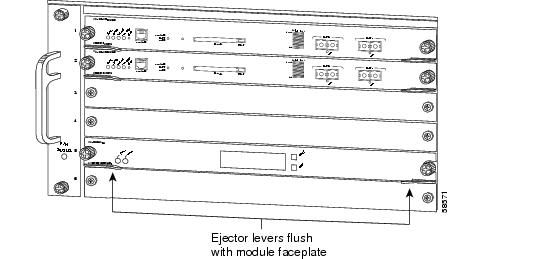
d.![]() While pressing down, simultaneously close the left and right ejector levers to fully seat the supervisor engine or module in the backplane connector. The ejector levers are fully closed when they are flush with the module faceplate. (See Figure 3.)
While pressing down, simultaneously close the left and right ejector levers to fully seat the supervisor engine or module in the backplane connector. The ejector levers are fully closed when they are flush with the module faceplate. (See Figure 3.)

Note![]() Failure to fully seat the module in the backplane connector can result in error messages.
Failure to fully seat the module in the backplane connector can result in error messages.
e.![]() Tighten the two captive installation screws on the supervisor engine or module.
Tighten the two captive installation screws on the supervisor engine or module.

Note![]() Make sure the ejector levers are fully closed before tightening the captive installation screws.
Make sure the ejector levers are fully closed before tightening the captive installation screws.
f.![]() Verify that the supervisor engine or module STATUS LED is lit. Check the STATUS LED periodically. If the STATUS LED changes from orange to green, the supervisor engine or module has successfully completed the boot process and is now online. If the STATUS LED remains orange or turns red, the supervisor engine or module has not successfully completed the boot process and may have encountered an error.
Verify that the supervisor engine or module STATUS LED is lit. Check the STATUS LED periodically. If the STATUS LED changes from orange to green, the supervisor engine or module has successfully completed the boot process and is now online. If the STATUS LED remains orange or turns red, the supervisor engine or module has not successfully completed the boot process and may have encountered an error.
Figure 1 Positioning the Module in a Horizontal Slot Chassis
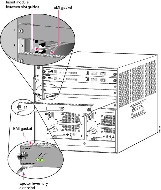
Figure 2 Clearing the EMI Gasket in a Horizontal Slot Chassis
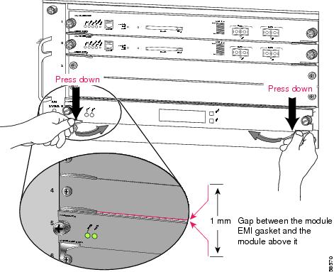
Figure 3 Ejector Lever Closure in a Horizontal Slot Chassis
a.![]() Position the supervisor engine or switching module in the slot. (See Figure 4.) Make sure that you align the sides of the switching-module carrier with the slot guides on the top and bottom of the slot.
Position the supervisor engine or switching module in the slot. (See Figure 4.) Make sure that you align the sides of the switching-module carrier with the slot guides on the top and bottom of the slot.
b.![]() Carefully slide the supervisor engine or module into the slot until the EMI gasket along the right edge of the module makes contact with the module in the slot adjacent to it and both ejector levers have closed to approximately 45 degrees with respect to the module faceplate. (See Figure 5.)
Carefully slide the supervisor engine or module into the slot until the EMI gasket along the right edge of the module makes contact with the module in the slot adjacent to it and both ejector levers have closed to approximately 45 degrees with respect to the module faceplate. (See Figure 5.)
c.![]() Using the thumb and forefinger of each hand, grasp the two ejector levers and exert a slight pressure to the left, deflecting the module approximately 0.040 inches (1 mm) to create a small gap between the module’s EMI gasket and the module adjacent to it. (See Figure 5.)
Using the thumb and forefinger of each hand, grasp the two ejector levers and exert a slight pressure to the left, deflecting the module approximately 0.040 inches (1 mm) to create a small gap between the module’s EMI gasket and the module adjacent to it. (See Figure 5.)

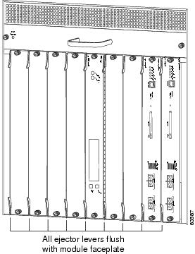
d.![]() While pressing on the ejector levers, simultaneously close them to fully seat the supervisor engine or module in the backplane connector. The ejector levers are fully closed when they are flush with the module faceplate. (See Figure 6.)
While pressing on the ejector levers, simultaneously close them to fully seat the supervisor engine or module in the backplane connector. The ejector levers are fully closed when they are flush with the module faceplate. (See Figure 6.)
e.![]() Tighten the two captive installation screws on the module.
Tighten the two captive installation screws on the module.

Note![]() Make sure the ejector levers are fully closed before tightening the captive installation screws.
Make sure the ejector levers are fully closed before tightening the captive installation screws.
f.![]() Verify that the supervisor engine or module STATUS LED is lit. Check the STATUS LED periodically. If the STATUS LED changes from orange to green, the supervisor engine or module has successfully completed the boot process and is now online. If the STATUS LED remains orange or turns red, the supervisor engine or module has not successfully completed the boot process and may have encountered an error.
Verify that the supervisor engine or module STATUS LED is lit. Check the STATUS LED periodically. If the STATUS LED changes from orange to green, the supervisor engine or module has successfully completed the boot process and is now online. If the STATUS LED remains orange or turns red, the supervisor engine or module has not successfully completed the boot process and may have encountered an error.
Figure 4 Positioning the Module in a Vertical Slot Chassis
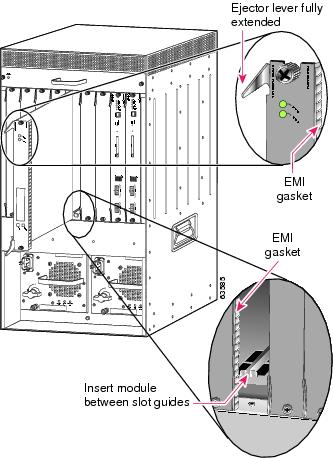
Figure 5 Clearing the EMI Gasket in a Vertical Slot Chassis
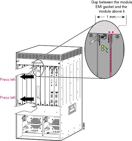
Figure 6 Ejector Lever Closure in a Vertical Slot Chassis
Cabling the Supervisor Engine or Module
After you have completed installing the supervisor engine or module, you are ready to the attach the interface cables. Depending on the module type, the interface cables may plug directly into receptacles on the module, or you may need to install a Gigabit Interface Converter (GBIC) or Small Form-Factor Pluggable (SFP) transceiver in the module and then connect the interface cable to the GBIC or SFP. For additional information on installing GBICs or SFP tranceiver modules, refer to the Gigabit Interface Converter Installation Note or the Cisco Small Form-Factor Pluggable Modules Installation Notes.
Verifying the Installation
This section describes how to verify the installation of modules.

Note![]() To verify the installation of a module on a switch or router running Cisco IOS, refer to the Catalyst 6500 Series Switch Cisco IOS Software Configuration Guide.
To verify the installation of a module on a switch or router running Cisco IOS, refer to the Catalyst 6500 Series Switch Cisco IOS Software Configuration Guide.
Verifying Newly Installed Modules
Enter the show module or show port [ mod_num/port_num ] command to verify that the system acknowledges the new modules and has brought them online.
Configuring the Modules
After you verify the module installation and check connectivity, you must configure the module. For complete configuration information, refer to the following publications:
- Catalyst 6500 Series Switch Software Configuration Guide
- Catalyst 6500 Series Switch Command Reference
- ATM Software Configuration and Command Reference — Catalyst 5000 Family and Catalyst 6500 Series Switches
- Cisco IOS Configuration Guides and Command References
- Cisco 7600 Series Router Software Configuration Guide
- Cisco 7600 Series Router Command Reference
Regulatory Standards Compliance
Catalyst 6500 series switching modules comply with the regulatory standards listed in the Regulatory Compliance and Safety Information for the Catalyst 6500 Series Switches publication. Cisco 7600 series routers comply with the regulatory standards listed in the Regulatory Compliance and Safety Information for the Cisco 7600 Series Router publication.
Related Documentation
For more detailed installation and configuration information, refer to these publications:
- Regulatory Compliance and Safety Information for the Catalyst 6500 Series Switches
- Regulatory Compliance and Safety Information for the Cisco 7600 Series Router
- Site Preparation and Safety Guide
- Catalyst 6500 Series Switch Module Installation Guide
- Catalyst 6500 Series Switch Software Configuration Guide
- Catalyst 6500 Series Switch Command Reference
- Cisco 7600 Series Router Installation Guide
- Cisco 7603 Router Installation Guide
- Cisco 7600 Series Router Quick Software Configuration Guide
- Cisco 7600 Series Router Software Configuration Guide
- Cisco 7600 Series Router Command Reference
- Catalyst 6500 Series Switch Cisco IOS Software Configuration Guide
- Gigabit Interface Converter Installation Note
- Cisco Small Form-Factor Pluggable Modules Installation Notes
- Installation Note for the CWDM Passive Optical System
Obtaining Documentation and Submitting a Service Request
For information on obtaining documentation, submitting a service request, and gathering additional information, see the monthly What’s New in Cisco Product Documentation, which also lists all new and revised Cisco technical documentation, at:
http://www.cisco.com/en/US/docs/general/whatsnew/whatsnew.html
Subscribe to the What’s New in Cisco Product Documentation as a Really Simple Syndication (RSS) feed and set content to be delivered directly to your desktop using a reader application. The RSS feeds are a free service and Cisco currently supports RSS version 2.0.

Contact Cisco
- Open a Support Case

- (Requires a Cisco Service Contract)


 Feedback