- Converged Access: Solution Overview
- Converged Access: Predeployment Checklist
- Converged Access: Management
- Converged Access: Basic Configuration
- Converged Access: Securing Networks with AAA and Cisco ISE
- Converged Access: Enabling Wireless
- Converged Access: WLAN Configuration
- Converged Access: Wireless AP and RF
- Converged Access: Wireless QoS
Converged Access: Wireless AP and RF
This chapter describes the best recommendation or practices of Radio Resource Management (RRM), beam forming, Fast SSID, and Cisco CleanAir features.
The examples provided in this chapter are sufficient to enable a converged access network. However, we recommended that you familiarize yourself with the validated design topics covered in the technology design guide too.
- Feature List
- Understanding Radio Resource Management
- Converged Access Topology Example
- Configuring RF and AP
- Wireless AP Features
- 802.11ac
- Channel Widths
- Beamforming
- Fast SSID Changing
- Cisco CleanAir
- Data Rates
Feature List
RRM Features
The following RRM features are covered in this chapter:
Wireless AP Features
The following Wireless access point (AP) features are covered in this chapter:
Understanding Radio Resource Management
RRM helps in providing seamless wireless connectivity to end users or clients and provides a real-time RF management of a wireless network. RRM enables switches to continuously monitor their associated APs for the following information:
-
Traffic load—The total bandwidth used for transmitting and receiving traffic. It enables wireless LAN managers to track and plan network growth ahead of the client demand.
-
Interference—The amount of traffic coming from other 802.11 sources.
-
Noise—The amount of non-802.11 traffic that is interfering with the currently assigned channel.
-
Coverage—The Received Signal Strength (RSSI) and signal-to-noise ratio (SNR) for all the connected clients.
RRM performs the following functions to provide the best RF quality of wireless access to end users:
-
RF Grouping
-
Transmit Power control (TPC)
-
Dynamic channel assignment (DCA)
-
Coverage hole detection mitigation (CHDM)
Mobility Controller
A Mobility Controller performs the following roles in RRM:
-
Mobility Controller can either be an RF group leader or a group member.
-
One Mobility Controller can act as an RF group leader with other Mobility Controllers, based on RF grouping and RF group selection.
-
The order of priority to elect the RF leader is based on the maximum number of APs the controller or switch can support.
-
The group leader determines a channel and TX power plan for the network and passes the information back to the RF group members.
-
The Mobility Controller pushes the power plan to a Mobility Agent to be used in the radios that belong to the Mobility Agent.
-
These channel and power plans are ultimately pushed down to individual radios.
Mobility Agent
A Mobility agent performs the following roles in RRM:
-
The Mobility Agent communicates with the Mobility Controller.
-
The Mobility Controller includes the MAC or IP address of the switch or controller while communicating with the Mobility Agent.
The Mobility Controller exchanges the following information with the switch or controller (group member):
-
Configurations (channel, power, channel width) for individual radios.
-
Polling requests for current configurations and RF measurements for individual radios.
The Mobility Agent communicates the following messages with the Mobility Controller (group leader):
-
RF measurements from radios (for example, load, noise, and neighbor information).
-
RF capabilities and configurations of individual radios.
The Mobility Agent sets channel, power, and channel width on the radios when directed by the Mobility Controller.
Dynamic Frequency Selection (DFS), coverage hole detection or mitigation, static channel or power configurations are performed by the Mobility Agent.
Converged Access Topology Example
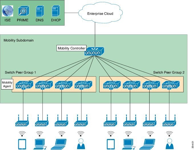
The following figure is used is to explain a converged access topology and for referencing configuration examples. It represents a typical converged access deployment scenario which covers most use cases. The Mobility Controller is found at the top of the diagram and is set up in as a stack for redundancy purposes. The switch stack connects to eight Mobility Agents which service the wireless clients. The eight Mobility Agents are divided equally into two different Switch Peer Groups (SPG). The entire setup belongs to a single mobility sub-domain. The access points connect directly to Mobility Agents, thus terminating CAPWAP tunnels on the Mobility Agents.
Configuring RF and AP
Make sure you complete the following steps before you proceed:
-
To configure RRM, configure the switch as a Mobility Controller.
-
To enable RRM in converged access deployment, a mobility tunnel should be active between a Mobility Controller and Mobility Agent. 
Note
To learn more about RRM, refer to Radio Resource Management Configuration Guide, Cisco IOS XE Release 3E guide.
Configuring RF Grouping
Before configuring RF grouping, ensure that you have created an RF group name and RF group leader, to run the subfunctions of TPC, DCA, and CHDM. The Mobility Controller is configured with an RF group name, which is sent to all APs points connected to the Mobility Controller. The RF group name is used by the APs as the shared secret for generating the hashed Message Integrity Check (MIC) in the neighbor messages.
Configuring an RF Group Leader
Perform the following steps to configure an RF group leader:
Configuring Transmit Power Control
Transmit Power Control (TPC) is configured to auto by default, per radio basis. We recommend that you retain the default configuration.
The Mobility Controller that is enabled as the RF leader dynamically controls access point (AP) transmit power under a real-time WLAN.
TPC seeks to lower an AP's power to reduce interference. However, in the case of sudden change in the RF coverage, for example, if an AP fails or becomes disabled, TPC can also increase power of the surrounding APs. This feature is different from coverage hole detection. While the coverage hole detection is connected to clients, TPC provides enough RF power to achieve the required coverage and avoid channel interference between APs.
Note | TPC is useful in identifying coverage holes and adjust the power accordingly. This provides seemless connectivity to the clients. |
Perform the following steps to configure TPC.
Configuring Dynamic Channel Assignment
Two adjacent APs on the same channel can cause either channel contention or signal collision. In collision, data is not received by the corresponding AP. The dynamic channel assignment (DCA) is useful in minimizing adjacent channel interference between the APs.
DCA is enabled by default on the RF leader, and operates to adjust channels automatically on all the access points in that RF domain.
It is the best practice to let RRM automatically configure all the 802.11a and 802.11b org channels based on availability. The RF leader automatically adjusts the channel unless it is configured to a setting other than auto.
To configure DCA, perform the following steps:
Configuring Coverage Hole Detection and Mitigation
Coverage Hole Detection and Mitigation (CHDM) is a per–controller configuration and not a global configuration. CHDM is enabled by default.
The RRM CHDM algorithm can detect areas of radio coverage in a wireless LAN that are below the level needed for robust radio performance. When an excising access point is relocated a notification is sent for additional access point .
The CHDM default values are sufficient for most environments. Unless directed otherwise, we recommend that you accept the default values.
To learn more about CHDM and coverage hole detection algorithm, refer to Radio Resource Management Configuration Guide, Cisco IOS XE Release 3E guide.
 Tip | For better CHDM monitoring, connect Cisco Prime to identify the areas for coverage and resolve client issues, if any. TPC gets adjusted automatically if there are issues in coverage, assuming that TPC is kept configured to the default value range. |
Perform the following steps to configure and verify CHDM:
Wireless AP Features
We recommend you to enable the wireless AP features because it helps in providing seamless roaming and connectivity.
Wireless and RF Prerequisites
Prior to wireless deployment, we recommend that you perform a thorough survey to ensure quality of service for your wireless clients. The requirements for voice and location deployments are stricter than for data services. Auto RF helps in channel and power settings management, but cannot correct a poor RF design.
A site survey must be performed with devices that match the power and propagation behavior of the devices to be used i n the real network. For example, do not use an older 802.11b or g radio with omni antenna to study coverage if you actual network will use a more modern dual radio for 802.11a or b org with n and 802.11ac data rates.
802.11ac
802.11ac provides enterprise networks with reliability and superior performance by supporting up to three spatial streams and 80-MHz-wide channels for a maximum data rate of 1.3 Gbps.
11ac feature allows companies to grow their network bandwidth dynamically for pervasive coverage or spot coverage, based on the high bandwidth demands of their user base, for example, in areas of high user congregation, such as libraries, cafeterias, and auditoriums. Companies have full control for how, where, and when to expand their wireless network.
802.11ac Data Rates(5 GHz)
802.11ac can support up to three spatial streams with MCS Index 9 and achieve data rate of 1300 Mbps for 80–MHz bandwidth with a guard interval of 400 ns.
Note | 802.11ac with a 80–Mhz bandwidth can support up to a maximum of five non-overlapping channels. For more information, refer to Cisco Aironet Access Point Module for 802.11ac Data Sheet. |
Channel Widths
11ac allows the bonding of 20–MHz channels into an 80–MHz–wide channel for 802.11ac usage and all clients must support 80–MHz. We recommend that you have 80–MHz–wide channel bandwidth set to utilize the 802.11ac functionality.
Configuring Channel Width
Device(config)# ap name AP dot11 5ghz channel width 80
Beamforming
Beamforming is the primary method of improving downlink performance (AP to client) that takes advantage of the multiple Multiple-Input Multiple-Output (MIMO) transmitters on the AP. The use of beamforming on downlink transmissions often results in a more balanced level of performance between uplink and downlink.
Cisco ClientLink is an implicit beamforming method that adjusts the downlink phase of each individual orthogonal frequency-division multiplexing (OFDM) subcarrier on each transmit antenna based on uplink channel estimates.
Note | The Cisco Aironet 3700 Series Access Point supports the Cisco ClientLink 3.0 and is able to beamform to 802.11ac clients, including 1, 2, and 3 spatial streams. It also supports all Cisco ClientLink 2.0 functionalities with legacy 11a org clients and 802.11n 1, 2, and 3 spatial stream clients. The Cisco Aironet 3600 Access Points support Cisco ClientLink 2.0 which beamforms to legacy 11a or g clients and 11n 1, 2, 3 spatial stream, but does not support Cisco ClientLink 3.0 (beamforming to 11ac clients). |
Configuring Beamforming
Perform the following steps to configure beamforming:
Fast SSID Changing
When fast SSID changing is enabled, the controller allows clients to move faster between SSIDs. Also, the client entry is not cleared and the delay is not enforced.
Configuring Fast SSID Changing
Perform the following steps to configure the fast SSID changing feature:
Cisco CleanAir
Cisco CleanAir technology uses silicon-level intelligence to create a spectrum-aware, self-healing, and self-optimizing wireless network that mitigates the impact of wireless interference, and offers performance protection for 802.11n and 802.11ac networks. All users of the shared spectrum can be seen (both native devices and foreign interferers). It also enables the network to act upon this information. For example, the interfering device can be manually removed or the system can automatically move the channel away from the source of interference.
To effectively detect and mitigate RF interference, enable Cisco CleanAir whenever possible.
Note | Only Cisco CleanAir-enabled APs can perform Cisco CleanAir spectrum monitoring. |
Enabling Cisco CleanAir
Cisco CleanAir is disabled by default and can only be enabled from a Mobility Controller. To enable Cisco CleanAir, perform the following steps:
| Step 1 | To configure
the Cisco CleanAir functionality to receive spectrum data on a 802.11 network,
use the following commands:
Device(config)# ap dot11 24ghz cleanair Device(config)# ap dot11 5ghz cleanair |
| Step 2 | To enable
interference detection, for example, from a jammer, use the following commands:
Device(config)# ap dot11 5ghz cleanair device jammer Device(config)# ap dot11 24ghz cleanair device bluetooth |
| Step 3 | To verify if
Cisco CleanAir is enabled on the 802.11 networks, use the following command:
Device# show ap dot11 24ghz cleanair config

CleanAir Solution................................ : Enabled
For more information, refer to Configuring Cisco CleanAir Guide. |
Data Rates
You must carefully plan the process to disable or enable data rates. If your coverage is sufficient, you can incrementally disable lower data rates one by one. Management frames such as ACK or beacons will be sent at the lowest mandatory rate (typically 1 Mbps), which slows down the entire throughput (the lowest mandatory rate consumes the most airtime).
We recommend that you do not have too many supported data rates so that clients can downshift their rate faster when re-transmitting. Typically, clients try to send at the fastest data rate they can, and if the frame does not make it through, they retransmit at the next lowest data rate, and so on until the frame goes through. The removal of some supported rates means that clients who retransmit a frame directly, downshift several data rates, which increases a frame's chance to go through at the second attempt.
-
If your design does not require low data rates, consider disabling the 802.11b data rates (1, 2, 5.5, and 11) and leave the rest enabled.
-
You by make a conscious decision to not disable rates below 11 Mbps in order to not stop the support of 802.11b-only clients.
Note | The following example should not be used as a strict guideline for every design. Note that these changes are sensitive and dependent on your RF coverage design. Conversely, if you are designing for a high-speed network that already has good RF coverage, disable the lowest data rate. |
The following example shows how to disable low data rates (5 GHz and 2.4 GHz):
 Device(config)# ap dot11 5ghz shutdown
 Device(config)# ap dot11 5ghz dot11n
 Device(config)# ap dot11 5ghz rate RATE_6M disable
 Device(config)# ap dot11 5ghz rate RATE_9M disable
 Device(config)# ap dot11 5ghz rate RATE_12M disable
 Device(config)# ap dot11 5ghz rate RATE_18M disable
 Device(config)# ap dot11 5ghz rate RATE_24M mandatory
 Device(config)# ap dot11 5ghz rate RATE_36M supported
 Device(config)# ap dot11 5ghz rate RATE_48M supported
 Device(config)# ap dot11 5ghz rate RATE_54M supported
 Device(config)# no ap dot11 5ghz shutdown

 Device(config)# ap dot11 24ghz shutdown
 Device(config)# ap dot11 24ghz dot11g
 Device(config)# ap dot11 24ghz dot11n
 Device(config)# ap dot11 24ghz rate RATE_24M mandatory
 Device(config)# ap dot11 24ghz rate RATE_1M disable
 Device(config)# ap dot11 24ghz rate RATE_2M disable
 Device(config)# ap dot11 24ghz rate RATE_5_5M disable
 Device(config)# ap dot11 24ghz rate RATE_6M disable
 Device(config)# ap dot11 24ghz rate RATE_9M disable
 Device(config)# ap dot11 24ghz rate RATE_11M disable
 Device(config)# ap dot11 24ghz rate RATE_12M supported
 Device(config)# ap dot11 24ghz rate RATE_18M supported
 Device(config)# ap dot11 24ghz rate RATE_36M supported
 Device(config)# ap dot11 24ghz rate RATE_48M supported
 Device(config)# ap dot11 24ghz rate RATE_54M supported
 Device(config)# no ap dot11 24ghz shutdown
 Feedback