Safety Warnings
This section includes the basic installation caution and warning statements. Read this section before you start the installation procedure. Translations of the warning statements appear in the RCSI guide on Cisco.com.
 Warning |
Before working on equipment that is connected to power lines, remove jewelry (including rings, necklaces, and watches). Metal objects will heat up when connected to power and ground and can cause serious burns or weld the metal object to the terminals. Statement 43 |
Warning |
Do not stack the chassis on any other equipment. If the chassis falls, it can cause severe bodily injury and equipment damage. Statement 48 |
Warning |
This product must be connected to a power-over-ethernet (PoE) IEEE 802.3af compliant power source or an IEC60950 compliant limited power source. Statement 353 |
Warning |
Read the wall-mounting instructions carefully before beginning installation. Failure to use the correct hardware or to follow the correct procedures could result in a hazardous situation to people and damage to the system. Statement 378 |
Warning |
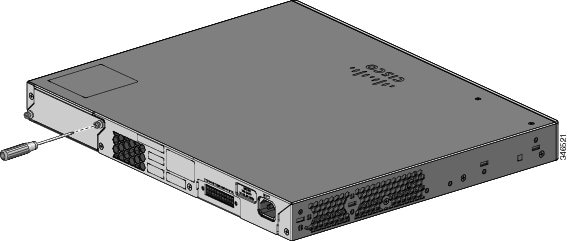
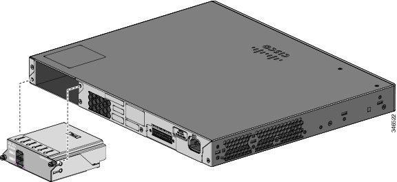
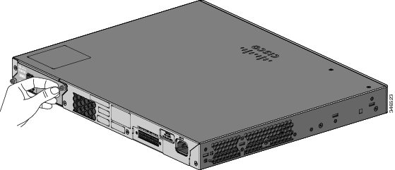
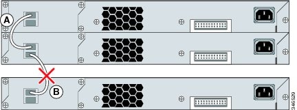
If a Cisco external power system is not connected to the switch, install the provided connector cover on the back of the switch. Statement 386 |
Warning |
Attach only the following Cisco external power system to the switch: PWR-RPS2300 Statement 387 |
Warning |
Do not work on the system or connect or disconnect cables during periods of lightning activity. Statement 1001 |
Warning |
Read the installation instructions before connecting the system to the power source. Statement 1004 |
Warning |
|
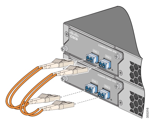
Warning |
Class 1 laser product. Statement 1008 |
Warning |
This unit is intended for installation in restricted access areas. A restricted access area can be accessed only through the use of a special tool, lock and key, or other means of security. Statement 1017 |
Warning |
The plug-socket combination must be accessible at all times, because it serves as the main disconnecting device. Statement 1019 |
Warning |
This equipment must be grounded. Never defeat the ground conductor or operate the equipment in the absence of a suitably installed ground conductor. Contact the appropriate electrical inspection authority or an electrician if you are uncertain that suitable grounding is available. Statement 1024 |
Warning |
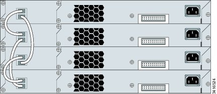
This unit might have more than one power supply connection. All connections must be removed to de-energize the unit. Statement 1028 |
Warning |
Only trained and qualified personnel should be allowed to install, replace, or service this equipment. Statement 1030 |
Warning |
Ultimate disposal of this product should be handled according to all national laws and regulations. Statement 1040 |
Warning |
For connections outside the building where the equipment is installed, the following ports must be connected through an approved network termination unit with integral circuit protection: 10/100/1000 Ethernet. Statement 1044 |
Warning |
When installing or replacing the unit, the ground connection must always be made first and disconnected last. Statement 1046 |
Warning |
To prevent the system from overheating, do not operate it in an area that exceeds the maximum recommended ambient temperature of: <113°F (45°C). Statement 1047 |
Warning |
This warning symbol means danger. You are in a situation that could cause bodily injury. Before you work on any equipment, be aware of the hazards involved with electrical circuitry and be familiar with standard practices for preventing accidents. Use the statement number provided at the end of each warning to locate its translation in the translated safety warnings that accompanied this device. Statement 1071 |
Warning |
Voltages that present a shock hazard may exist on Power over Ethernet (PoE) circuits if interconnections are made using uninsulated exposed metal contacts, conductors, or terminals. Avoid using such interconnection methods, unless the exposed metal parts are located within a restricted access location and users and service people who are authorized within the restricted access location are made aware of the hazard. A restricted access area can be accessed only through the use of a special tool, lock and key or other means of security. Statement 1072 |
Warning |
No user-serviceable parts inside. Do not open. Statement 1073 |
Warning |
Installation of the equipment must comply with local and national electrical codes. Statement 1074 |
Warning |
To prevent airflow restriction, allow clearance around the ventilation openings to be at least: 3 inches (7.6 cm). Statement 1076 |
Warning |
Hot surface. Statement 1079 |
Applies to the Catalyst 2960X-24PSQ-L switches.


 Feedback