Power Supply Module Overview
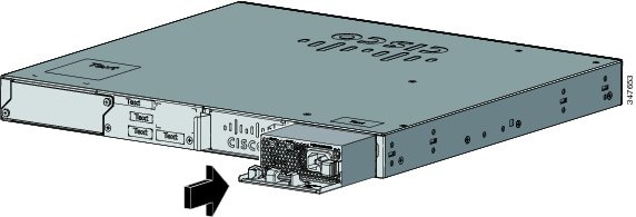
The switch operates with either one or two active power supply modules. You can use two AC modules, or one module and a blank cover.
 Note |
The Catalyst 2960XR-48FPD-I and 2960XR-48FPS-I only support the PWR-C2-1025WAC power supply. You cannot use the PWR-C2-250WAC and PWR-C2-640WAC power supplies in these switches. |
|
Part Number |
Description |
|---|---|
|
PWR-C2-250WAC= |
250-W AC power supply module |
|
PWR-C2-640WAC= |
640-W AC power supply module |
|
PWR-C2-1025WAC= |
1025-W AC power supply module |
The 250-W and 640-W AC power supply modules are autoranging units that support input voltages between 100 and 240 VAC. The 1025-W power supply module is an autoranging unit that supports input voltages between 115 and 240 VAC. All power supply modules have internal fans. All switches ship with a blank cover in the second power supply slot.
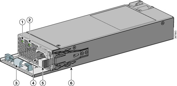
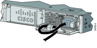
Each AC power supply module has a power cord for connection to an AC power outlet.

|
1 |
AC OK LED |
4 |
AC power cord connector |
|
2 |
PS OK LED |
5 |
Release latch |
|
3 |
AC power cord retainer |
6 |
Power supply |
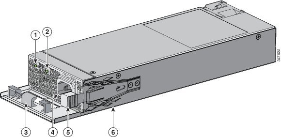
|
1 |
AC OK LED |
4 |
AC power cord connector |
|
2 |
PS OK LED |
5 |
Release latch |
|
3 |
AC power cord retainer |
6 |
Power supply |
|
1 |
AC OK LED |
4 |
AC power cord connector |
|
2 |
PS OK LED |
5 |
Release latch |
|
3 |
AC power cord retainer |
6 |
Power supply |
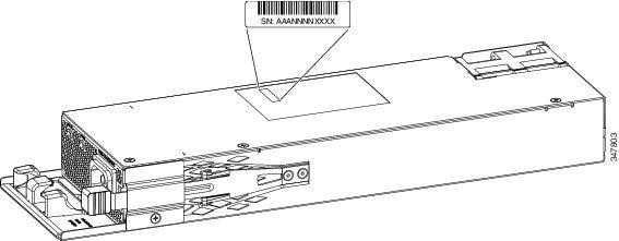
If no power supply is installed in a power supply slot, install a power supply slot cover.
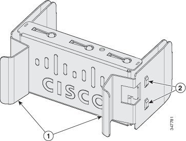
|
1 |
Release handles |
2 |
Retainer clips |
The power supply modules have two status LEDs.
|
AC OK |
Description |
PS OK |
Description |
|---|---|---|---|
|
Off (AC LED is off) |
No AC input power. |
Off |
Output is disabled, or input is outside operating range. |
|
Green |
AC input power is present. |
Green |
Power output to switch. |
|
Red |
Output has failed. |


 Feedback