Switch Models
|
Switch Model |
Software Image |
Description |
|---|---|---|
|
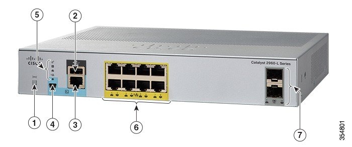
WS-C2960L-8TS-LL |
Lan Lite |
8 10/100/1000 Ethernet ports; 2 1-Gigabit small form-factor pluggable (SFP) module uplink slots. |
|
WS-C2960L-8PS-LL |
Lan Lite |
8 10/100/1000 Power over Ethernet plus (PoE+) ports (PoE budget of 67W); 2 1-Gigabit small form-factor pluggable (SFP) module uplink slots. |
|
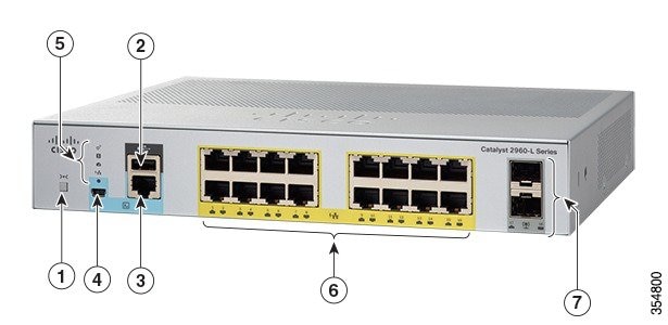
WS-C2960L-16TS-LL |
Lan Lite |
16 10/100/1000 Ethernet ports; 2 1-Gigabit small form-factor pluggable (SFP) module uplink slots. |
|
WS-C2960L-16PS-LL |
Lan Lite |
16 10/100/1000 Power over Ethernet plus (PoE+) ports (PoE budget of 120W); 2 1-Gigabit small form-factor pluggable (SFP) module uplink slots. |

 Feedback