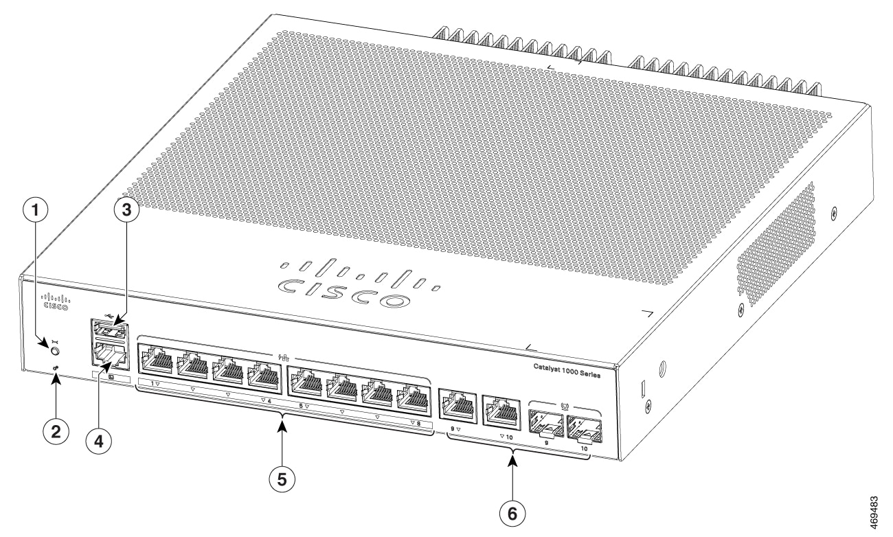
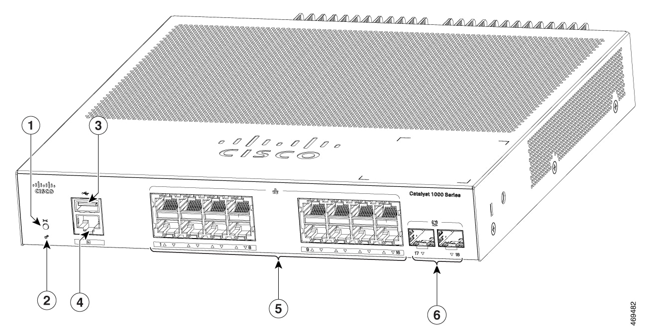
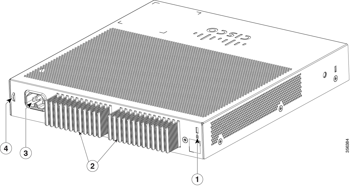
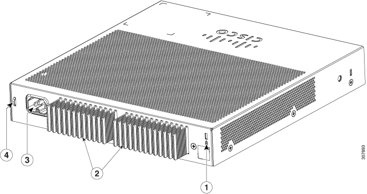
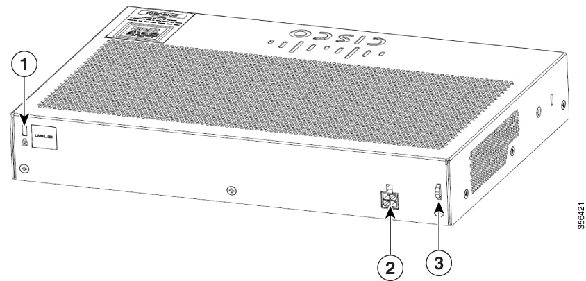
Product Overview

The Cisco Catalyst 1000 Series switches are fixed-configuration, Gigabit Ethernet switches that provide entry-level enterprise-class Layer 2 access for branch offices, conventional workspace, and out-of-wiring closet applications.

Cisco Catalyst 1000 Series switches provide support for the following features:

  • 8 or 16 Gigabit Ethernet ports with line-rate forwarding performance.

  • Two Gigabit Small Form-Factor Pluggable (SFP) uplinks.

  • Power over Ethernet Plus (PoE+) support with up to 240W of PoE budget and Perpetual PoE.

  • Fanless operation with operational temperature up to 50°C for deployment outside the wiring closet.

  • Reduced power consumption and advanced energy management.

  • RJ-45 console port.

  • USB Type A port supports file system.

Switch Models

Table 1. Cisco Catalyst 1000 8-Port and 16-Port Switch Models and Description

Switch Model

Description

C1000-8T-2G-L

8 10/100/1000 Ethernet ports; 2 1-Gigabit small form-factor pluggable (SFP) module uplink slots or 2 RJ-45 slots.

C1000-8T-E-2G-L

Externally powered; 8 10/100/1000 Ethernet ports; 2 1-Gigabit SFP module uplink slots or 2 RJ-45 slots.

C1000-8P-2G-L

8 10/100/1000 Power over Ethernet plus (PoE+) ports (PoE budget of 67W); 2 1-Gigabit SFP module uplink slots or 2 RJ-45 slots.

C1000-8P-E-2G-L

Externally powered; 8 10/100/1000 PoE+ ports (PoE budget of 67W); 2 1-Gigabit SFP module uplink slots or 2 RJ-45 slots.

C1000-8FP-2G-L

8 10/100/1000 PoE+ ports (PoE budget of 120W); 2 1-Gigabit SFP module uplink slots or 2 RJ-45 slots.

C1000-8FP-E-2G-L

Externally powered; 8 10/100/1000 PoE+ ports (PoE budget of 120W); 2 1-Gigabit SFP module uplink slots or 2 RJ-45 slots.

C1000-16T-2G-L

16 10/100/1000 Ethernet ports; 2 1-Gigabit small form-factor pluggable (SFP) module uplink slots.

C1000-16T-E-2G-L

Externally powered; 16 10/100/1000 Ethernet ports; 2 1-Gigabit SFP module uplink slots.

C1000-16P-2G-L

16 10/100/1000 Power over Ethernet plus (PoE+) ports (PoE budget of 120W); 2 1-Gigabit small form-factor pluggable (SFP) module uplink slots.

C1000-16P-E-2G-L

Externally powered; 16 10/100/1000 PoE+ ports (PoE budget of 120W); 2 1-Gigabit SFP module uplink slots.

C1000-16FP-2G-L

16 10/100/1000 PoE+ ports (PoE budget of 240W); 2 1-Gigabit SFP module uplink slots.

Front Panel

This section describes the front panel components of an 8-port and 16-port Cisco Catalyst 1000 switch.

  • 8 or 16 downlink Ethernet ports of one of these types:

    • 10/100/1000

    • 10/100/1000 PoE+

  • 2 SFP module ports

  • RJ-45 console port

  • USB Type A port

  • LEDs

  • Reset button

Figure 1. Front Panel of an 8-Port Cisco Catalyst C1000 PoE Switch

1

Reset button

4

RJ-45 Console Port

2

System LEDs

5

8 10/100/1000 PoE+ ports

3

USB Type A port

6

Combo ports (2 GE Copper ports and 2 SFP module ports)

Figure 2. Front Panel of a 16-Port Cisco Catalyst 1000 PoE Switch

1

Reset button

4

RJ-45 Console Port

2

System LEDs

5

16 10/100/1000 PoE+ ports

3

USB Type A port

6

SFP module slots

PoE Ports

The ports provide PoE support for devices compliant with IEEE 802.3af and IEEE 802.3at and also provide PoE support for Cisco IP Phones and Cisco Aironet Access Points. The PoE switch ports are Power Source equipment (PSE) capable and source power to PD devices connected to the downlink ports. A switch can source POE power of up to 30.8W per port.

Depending on the switch model and the number of PoE ports, the maximum switch power output varies between 67 W to 740 W. On a per-port basis, you can control whether or not a port automatically provides power when an IP phone or an access point is connected.

The PoE ports use RJ-45 connectors with Ethernet pinouts. The 10BASE-T, 100BASE-TX, 1000BASE-T traffic requires Category 5 or Category 5e twisted pair (UTP) cable. The 10BASE-T traffic can use Category 3 or 
Category 4 UTP cable.

10/100/1000 Ports

The 10/100/1000 ports use RJ-45 connectors with Ethernet pinouts. The maximum cable length is 
328 feet (100 meters). The 10BASE-T, 100BASE-TX, 1000BASE-T traffic requires Category 5 or Category 5e twisted pair (UTP) cable. The 10BASE-T traffic can use Category 3 or 
Category 4 UTP cable.

Console Port

The console ports connect the switch to a PC running Microsoft Windows or to a terminal server.

RJ-45 console port (EIA/TIA-232) connection uses an RJ-45-to-DB-9 female cable.

SFP Module Slots


Note

The Cisco Catalyst 1000 Series Fast Ethernet Switches do not support SFP+ module slots.


The switch has two 1G SFP module slots. The SFP modules provide copper or fiber-optic connections to other devices. These transceiver modules are field replaceable, and provide the uplink interfaces when installed in an SFP module slot. The SFP modules have LC connectors for fiber-optic connections or RJ-45 connectors for copper connections. The SFP slots support only SFP modules.

For Cisco SFP modules documentation, including compatibility matrixes, refer to this URL: http://www.cisco.com/en/US/products/hw/modules/ps5455/products_device_support_tables_list.html

Table 2. Port mapping for Cisco Catalyst 1000 8-Port Switch models
1-GigabitEthernet ports

GigabitEthernet1/0/9

GigabitEthernet1/0/10

Table 3. Port mapping for Cisco Catalyst 1000 16-Port Switch models
1-GigabitEthernet ports

GigabitEthernet1/0/17

GigabitEthernet1/0/18

LEDs

You can use the switch system and port LEDs to monitor switch activity and performance.

Figure 3. System LED for a Cisco Catalyst 1000 Series Switch

1

SYST LED (system)

2

Port LEDs

System LED

Color System Status

Off

System is not powered on.

Green

System is operating normally.

Amber

System is receiving power but is not operating properly.

Blinking Green

POST is in progress.

Port LEDs


Note

Physically, there is no amber LED on the device. For all LED-related information of the device, run the show hardware led command in privileged EXEC mode.


RJ-45 ports and SFP-module slots have port LEDs. These LEDs, as a group or individually, provide information about the switch and about the individual ports.

LED Color Description

Off

No link or port was administratively shut down or port was STP blocked.

Green

Link present.

Blinking Green

Activity. Port is sending or receiving data.

Rear Panel

This section describes the rear panel components of Cisco Catalyst 1000 8-port and 16-port switches.

  • A security slot

  • An AC power connector

  • A loop (for the optional power cord retainer)

  • Heat sink fins (PoE models only)

Figure 4. Rear Panel of a Non-PoE Switch

1

Security Slot

3

A loop (for the optional power cord retainer)

2

An AC power connector

Figure 5. Rear Panel of a PoE Switch (All models except C1000-16FP-2G-L)
Figure 6. Rear Panel of a C1000-16FP-2G-L POE Switch

1

Security Slot

3

An AC power connector

2

Heat sink fins

4

A loop (for the optional power cord retainer)

Figure 7. Rear Panel of an Externally Powered Switch

1

Security Slot

3

A loop (for the optional power cord retainer)

2

A DC power connector

Internal Power Supply

The internal power supply is an autoranging unit that supports input voltages between 100 and 240 VAC (max of 90V to 264V). The AC frequency range of the power supply is 50Hz/60Hz. Plug the AC power cord into the AC power connector and into an AC power outlet.

Security Slot

The switches have security slots on the rear panel. You can install an optional cable lock, such as the type that is used to secure a laptop computer, to secure the switch.

Figure 8. Switch Rear Panel

Network Configurations

See the switch software configuration guide for network configuration concepts and examples of using the switch to create dedicated network segments and interconnecting the segments through Fast Ethernet and Gigabit Ethernet connections.