OSPFv2 NSSA Option

Feature History for OSPFv2 NSSA

This table provides release and platform support information for the features explained in this module.

These features are available in all the releases subsequent to the one they were introduced in, unless noted otherwise.

Release

Feature Name and Description

Supported Platform

Cisco IOS XE 17.18.1

OSPFv2 NSSA: The OSPFv2 NSSA is a network optimization feature that allows a central site that runs on OSPF protocol to connect to a remote site that runs on any other routing protocol.

Cisco C9610 Series Smart Switches

OSPFv2 NSSA

The OSPFv2 NSSA is a network optimization feature that allows a central site that runs on OSPF protocol to connect to a remote site that runs on any other routing protocol.

Without OSPFv2 NSSA

Without OSPFv2 NSSA, the following happens:

  • OSPF stub areas do not allow the redistribution from other protocols like RIP (Routing Information Protocol).

  • You must maintain two routing protocols: OSPF in the core and RIP at the edge.

  • The stub area cannot import external routes from the remote network.

Key components in OSPFv2 NSSA

  • Autonomous System Border Router (ASBR): ASBRs connect an OSPF network and a non-OSPF network (or another OSPF domain if routes are being explicitly redistributed). The ASBR redistributes routes from RIP (or another protocol) into OSPF NSSA as type 7 LSAs.

  • Area Border Router (ABR): ABRs connect regular areas to the backbone (Area 0). An ABR converts type 7 LSAs to type 5 LSAs, allowing the rest of the OSPF domain to learn about the external routes.

  • Route summarization: Route summarization is the process of combining a group of contiguous network addresses into a single summary address. This reduces the size of routing tables and improves routing efficiency. In OSPF, summarization is performed at Area Border Routers (ABRs) and Autonomous System Boundary Routers (ASBRs). If an OSPF area contains multiple contiguous subnets, the ABR can be configured to advertise a single summary route to other areas instead of multiple individual routes.

How OSPFv2 NSSA works

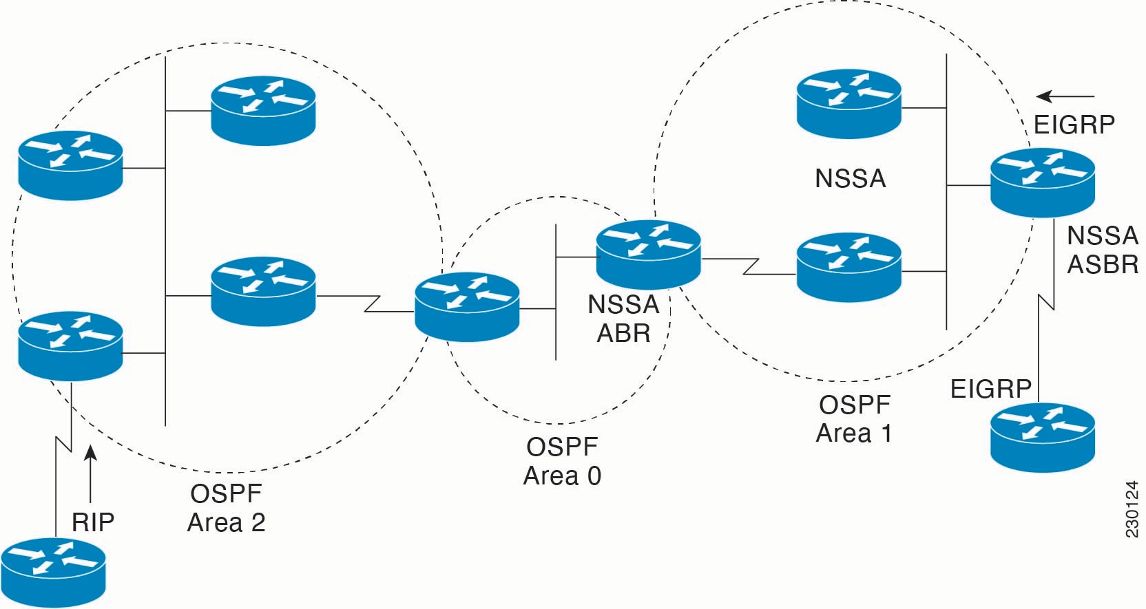
Figure 1. OSPF NSSA

The figure shows a network diagram that contains

  • OSPF Area 0 (Backbone Area): This is the central OSPF area, acting as the backbone that connects other OSPF areas. It contains at least two devices, one of which is an NSSA ABR.

  • OSPF Area 2: This area connects to OSPF Area 0 via an ABR (Area Border Router). It also connects to an external network running RIP (Routing Information Protocol).

  • OSPF Area 1 (NSSA - Not-So-Stubby Area): This is a special type of OSPF area. It connects to OSPF Area 0 via an NSSA ABR and also connects to an external network running EIGRP (Enhanced Interior Gateway Routing Protocol) via an NSSA ASBR.

  • ABR (Area Border Router): Devices that connect one OSPF area to another (e.g., the router between OSPF Area 2 and OSPF Area 0, and the NSSA ABR between OSPF Area 0 and OSPF Area 1). ABRs maintain separate link-state databases for each area they are connected to. They also summarize routes between areas.

  • NSSA ABR (Not-So-Stubby Area ABR): This ABR connects the NSSA (Area 1) to the backbone (Area 0). It is responsible for translating Type 7 LSAs (generated by the NSSA ASBR for external routes) into Type 5 LSAs, which are then flooded into the backbone area.

  • NSSA ASBR (Autonomous System Boundary Router): This switch is located within the NSSA (Area 1) and connects the OSPF domain to an external routing domain (EIGRP in this case). It imports external EIGRP routes into OSPF as Type 7 LSAs.

  • IP (Routing Information Protocol): An external network running RIP is connected to OSPF Area 2. Routes from this RIP domain would be redistributed into OSPF by the ASBR (which is also an ABR in this case) connecting Area 2 to the RIP network.

  • EIGRP (Enhanced Interior Gateway Routing Protocol): An external network running EIGRP is connected to OSPF Area 1 via the NSSA ASBR. This NSSA ASBR redistributes EIGRP routes into OSPF as Type 7 LSAs within Area 1.

How it works

  • Devices within each OSPF area exchange link-state information and build their respective topological databases.

  • ABRs summarize routes between areas. For example, Area 2 routes are summarized and sent to Area 0, and Area 0 routes are sent to Area 2.

  • Routes from the RIP domain are imported into OSPF Area 2 and then propagated through the OSPF backbone.

  • EIGRP routes are imported by the NSSA ASBR into OSPF Area 1 as Type 7 LSAs. The NSSA ABR then converts these Type 7 LSAs into Type 5 LSAs, which are then flooded into OSPF Area 0 (the backbone) and subsequently to other areas if needed. This mechanism allows external routes to be injected into a stub-like area without making it a full external area.

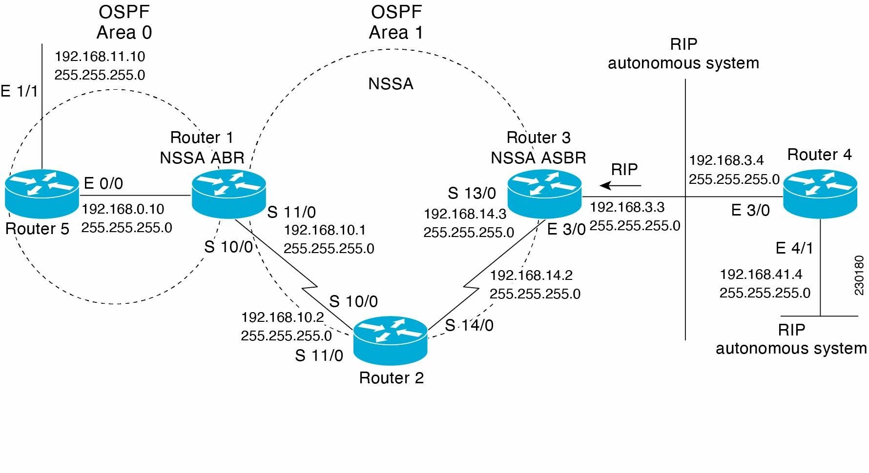
Figure 2. OSPF NSSA Network with NSSA ABR and ASBR Devices

The following table shows information about the above figure.

OSPF Area 0 (Backbone Area)

Switch 5

  • Connects to OSPF Area 0.

  • Interface E 1/1 has IP address 192.168.11.10 with a subnet mask of 255.255.255.0.

  • Interface E 0/0 connects to Switch 1 with IP address 192.168.0.10/24.

Switch 1 (NSSA ABR - Not-So-Stubby Area Area Border Router)

  • Acts as an Area Border Router, connecting OSPF Area 0 to OSPF Area 1.

  • Interface E 0/0 connects to Switch 5 with IP address 192.168.0.10/24.

  • Interfaces S 10/0 (192.168.10.1/24) and S 11/0 (implied, but shares the 192.168.10.1/24 network with S 10/0 on Switch 2) connect to Switch 2, extending into OSPF Area 1.

OSPF Area 1 (NSSA - Not-So-Stubby Area)

Switch 2

  • Part of OSPF Area 1.

  • Interface S 11/0 connects to Switch 1 with IP address 192.168.10.2/24.

  • Interface S 14/0 connects to Switch 3 with IP address 192.168.14.2/24.

Switch 3 (NSSA ASBR - Not-So-Stubby Area Autonomous System Boundary Router)

  • Acts as an Autonomous System Boundary Router, connecting OSPF Area 1 to the RIP autonomous system.

  • Interface S 13/0 connects to Switch 2 with IP address 192.168.14.3/24.

  • Interface E 3/0 connects to Switch 4, participating in both OSPF (within Area 1) and RIP (with the RIP autonomous system) with IP address 192.168.3.3/24.

RIP Autonomous System

Switch 4

  • Part of the RIP autonomous system.

  • Interface E 3/0 connects to Switch 3 with IP address 192.168.3.4/24.

  • Interface E 4/1 has IP address 192.168.41.4/24, representing another network within the RIP domain.

How it works

  • Devices within each OSPF area exchange link-state information and build their respective topological databases.

  • RIP routes are imported by the NSSA ASBR (Switch 2) into OSPF Area 1 as Type 7 LSAs. The NSSA ABR (Switch 2) then converts these Type 7 LSAs into Type 5 LSAs, which are then flooded into OSPF Area 0 (the backbone). This mechanism allows external routes to be injected into a stub-like area without making it a full external area.

How to configure OSPFv2 NSSA

This section provides information on how to configure OSPFv2 NSSA.

Configure an OSPFv2 NSSA area and its parameters

Perform this procedure to configure an OSPFv2 NSSA area and it parameters.

Procedure


Step 1

enable

Example:

Device> enable

Enables privileged EXEC mode.

Enter your password, if prompted.

Step 2

configure terminal

Example:

Device# configure terminal

Enters global configuration mode.

Step 3

router ospf process-id [vrf vrf-name]

Example:

Device(config)# router ospf 15

Enables OSPF routing and enters router configuration mode.

  • process-id : The process ID is an internally used identification parameter that is locally assigned. Each OSPF process has a unique process ID.

    Process ID can be a positive integer from 1 to 65535.

  • vrf: Indicates that the OSPF process is being configured for a specific VRF.

  • vrf-name : Specifies the name of the VRF for which this OSPF process is being created.

Step 4

redistribute protocol [process-id] [as-number] [include-connected {level-1 | level-1-2 | level-2} [metric metric-value | transparent] [metric-type type-value] [match {internal | external 1 | external 2}] [subnets] [nssa-only] [tag tag-value] [route-map map-tag]

Example:

Device(config-router)# redistribute rip subnets

Redistributes routes from one routing domain into another routing domain.

  • protocol : Specifies the source of the routes to be redistributed. Common options include:

    • connected : Redistributes directly connected networks that are not already part of the OSPF process.

    • static : Redistributes static routes configured on the router.

    • bgp : Redistributes routes learned via BGP.

    • eigrp : Redistributes routes learned via EIGRP.

    • rip : Redistributes routes learned via RIP.

    • ospf : Redistributes routes from another OSPF process (e.g., if running multiple OSPF instances or different process IDs).

    • isis : Redistributes routes learned via IS-IS.

  • process-id : (Optional) If the source protocol (e.g., EIGRP, OSPF, RIP) uses a process ID, you specify it here to identify the specific instance from which routes should be taken.

  • as-number : (Optional) If the source protocol (e.g., BGP or EIGRP) uses an Autonomous System (AS) number, you specify it here. This is often used interchangeably with process-id for protocols that use AS numbers.

  • include-connected {level-1 | level-1-2 | level-2} : (Optional) This parameter is typically specific to IS-IS redistribution into OSPF, or sometimes OSPF into IS-IS, or even OSPF into OSPF (though less common). It refers to the IS-IS routing levels:

    • level-1: Redistributes Level-1 IS-IS routes.

    • level-2: Redistributes Level-2 IS-IS routes.

    • level-1-2: Redistributes both Level-1 and Level-2 IS-IS routes.

    • This part of the syntax suggests a context where IS-IS is the source protocol.

  • metric {metric-value | transparent} : This is a critical parameter for redistribution. When routes are redistributed from one protocol to another, they need to be assigned a metric that is meaningful to the destination protocol.

    • metric-value : A specific numerical value to assign as the metric. The meaning of this value depends on the destination protocol (e.g., hop count for RIP, cost for OSPF).

    • transparent : This attempts to carry the original metric information across, but its effectiveness can vary depending on the protocols involved.

  • metric-type type-value : (Optional) For OSPF, this is crucial for how external routes are handled:

    • type-1 (E1): The cost to the external destination is the sum of the external metric and the internal OSPF cost to reach the ASBR. This is often preferred for more accurate path selection.

    • type-2 (E2): The cost to the external destination is only the external metric, regardless of the internal OSPF cost to reach the ASBR. This is the default if not specified. Type 2 routes are always preferred over Type 1 routes if their external metric is the same.

  • match {internal | external 1 | external 2} : This parameter is specific to OSPF when redistributing OSPF routes into another protocol. It allows you to specify which types of OSPF routes to redistribute:

    • internal : Redistributes OSPF intra-area (Type 1) and inter-area (Type 2) routes.

    • external 1 : Redistributes OSPF external Type 1 routes.

    • external 2 : Redistributes OSPF external Type 2 routes.

  • nssa-only : (Optional) This keyword is specifically used when redistributing routes into a Not-So-Stubby Area (NSSA). When nssa-only is specified, the redistributed routes will be advertised as Type 7 LSAs within the NSSA, and then translated to Type 5 LSAs by the NSSA ABR for propagation to other areas. Without this parameter, redistribution into an NSSA might not be allowed or might behave differently

  • tag tag-value : (Optional) Assigns a numerical tag to the redistributed routes. This tag can be used later in route maps or distribute lists for filtering or policy-based routing.

  • route-map map-tag : (Optional) A very powerful and commonly used parameter. It references a route-map that provides granular control over which routes are redistributed and how their attributes (like metric, metric-type, tag) are modified during the redistribution process.

  • subnets : This parameter is specific to OSPF. By default, OSPF only redistributes classful networks. To redistribute subnetted networks (which is almost always desired in modern networks), you must include the subnets keyword. Without it, only major network numbers (e.g., 10.0.0.0/8, 192.168.1.0/24) would be redistributed.

Step 5

network ip-address wildcard-mask area area-id

Example:

Device(config-router)# redistribute rip subnets

Defines the interfaces on which OSPF runs and defines the area ID for those interfaces.

  • ip-address : The network address of the interface you want to enable OSPF on.

  • wildcard-mask : Inverse mask that, together with the ip-address, selects a range of IP addresses.

  • area-id : The OSPF area (in decimal or dotted-decimal format) to which the interface will be assigned.

Step 6

area area-id nssa [no-redistribution] [default-information-originate] [metric metric-type] [no-summary] [nssa-only]

Example:

Device(config-router)# area 1 nssa

(Optional) Defines an area as a NSSA. Every device within the same area must agree that the area is NSSA. Select one of these keywords:

  • no-redistribution : Select when the router is an NSSA ABR and you want the redistribute command to import routes into normal areas, but not into the NSSA.

  • default-information-originate : Select on an ABR to import type 7 LSAs into the NSSA.

  • metric metric-type : (Optional) Sets the metric for the default route.

    (Optional) Specifies the type (1 or 2) for the default route.

  • no-summary : Select to not send summary LSAs into the NSSA.

  • nssa : Disallows the area from functioning as a normal area if the NSSA configuration is removed (rarely used in practice).

Step 7

summary-address prefix-mask [not-advertise] [tag tag] [nssa-only]

Example:

Device(config-router)# summary-address 10.1.0.0 255.255.0.0 not-advertise

Controls the route summarization and filtering during the translation and limits the summary to NSSA areas

  • prefix-mask : The summarized network address and the network mask for the summary route.

  • not-advertise : (Optional) Suppresses the summary route advertisement.

  • tag tag : (Optional) Associates a tag with the summary route for policy or routing decisions.

  • nssa-only : (Optional) Advertises the summary only as a Type 7 LSA for NSSA areas.

Step 8

end

Example:

Device(config-router)# end

Exits router configuration mode and returns to privileged EXEC mode.


Configure an NSSA ABR as a forced NSSA LSA translator

Perform this procedure to configure an NSSA ABR as a forced NSSA LSA translator.

Procedure


Step 1

enable

Example:

Device> enable

Enables privileged EXEC mode.

Enter your password, if prompted.

Step 2

configure terminal

Example:

Device# configure terminal

Enters global configuration mode.

Step 3

router ospf process-id [vrf vrf-name]

Example:

Device(config)# router ospf 15

Enables OSPF routing and enters router configuration mode.

  • process-id : The process ID is an internally used identification parameter that is locally assigned. Each OSPF process has a unique process ID.

    Process ID can be a positive integer from 1 to 65535.

  • vrf: Indicates that the OSPF process is being configured for a specific VRF.

  • vrf-name : Specifies the name of the VRF for which this OSPF process is being created.

Step 4

area area-id nssa translate type7 always

Example:

Device(config-router)# area 10 nssa translate type7 always

Configures a NSSA ABR device as a forced NSSA LSA translator.

Note


This command can be used if RFC 3101 is disabled and RFC 1587 is used.

  • area-id : The OSPF area number or address in dotted-decimal format.

  • always : Manually force this ABR to always be the translator, ensuring consistent LSA translation and avoiding translator role changes due to device restarts or network topology changes.

Step 5

area area-id nssa translate type7 suppress-fa

Example:

Device(config-router)# area 10 nssa translate type7 suppress-fa

Allows ABR to suppress the forwarding address in translated Type-5 LSA.

Step 6

end

Example:

Device(config-router)# end

Exits router configuration mode and returns to privileged EXEC mode.


Disable RFC 3101 compatibility and enable RFC 1587 compatibility

Perform this task to disable RFC 3101 compatibility and enable RFC 1587 compatibility.

Procedure


Step 1

enable

Example:

Device> enable

Enables privileged EXEC mode.

Enter your password, if prompted.

Step 2

configure terminal

Example:

Device# configure terminal

Enters global configuration mode.

Step 3

router ospf process-id [vrf vrf-name]

Example:

Device(config)# router ospf 15

Enables OSPF routing and enters router configuration mode.

  • process-id : The process ID is an internally used identification parameter that is locally assigned. Each OSPF process has a unique process ID.

    Process ID can be a positive integer from 1 to 65535.

  • vrf: Indicates that the OSPF process is being configured for a specific VRF.

  • vrf-name : Specifies the name of the VRF for which this OSPF process is being created.

Step 4

compatible rfc1587

Example:

Device(config-router)# compatible rfc1587

Enables the device to be RFC 1587 compliant.

Step 5

end

Example:

Device(config-router)# end

Enables the device to be RFC 1587 compliant.


Configuration examples for OSPFv2 NSSA

In the following example, an OSPF stub network is configured to include OSPF Area 0 and OSPF Area 1, using five devices. Device 3 is configured as the NSSA ASBR. Device 2 configured to be the NSSA ABR. OSPF Area 1 is defined as a NSSA.

Device 1


Device# hostname Device1
!
interface Loopback1
    ip address 10.1.0.1 255.255.255.255
!
interface Ethernet0/0
    ip address 192.168.0.1 255.255.255.0
    ip ospf 1 area 0
    no cdp enable
!
interface Serial10/0
    description Device2 interface s11/0
    ip address 192.168.10.1 255.255.255.0
    ip ospf 1 area 1
    serial restart-delay 0
    no cdp enable
!
router ospf 1
    area 1 nssa
!
end

Device 2

Device# hostname Device2
!!
interface Loopback1
    ip address 10.1.0.2 255.255.255.255
!
    interface Serial10/0
    description Device1 interface s11/0
    no ip address
    shutdown
    serial restart-delay 0
    no cdp enable
!
interface Serial11/0
    description Device1 interface s10/0
    ip address 192.168.10.2 255.255.255.0
    ip ospf 1 area 1
    serial restart-delay 0
    no cdp enable
!
interface Serial14/0
    description Device3 interface s13/0
    ip address 192.168.14.2 255.255.255.0
    ip ospf 1 area 1
    serial restart-delay 0
    no cdp enable
!
router ospf 1
    area 1 nssa
!
end

Device 3

Device# hostname Device3
!
interface Loopback1
    ip address 10.1.0.3 255.255.255.255
!
interface Ethernet3/0
    ip address 192.168.3.3 255.255.255.0
    no cdp enable
!
interface Serial13/0
    description Device2 interface s14/0
    ip address 192.168.14.3 255.255.255.0
    ip ospf 1 area 1
    serial restart-delay 0
    no cdp enable
!
router ospf 1
    log-adjacency-changes
    area 1 nssa
    redistribute rip subnets
!
router rip
    version 2
    redistribute ospf 1 metric 15
    network 192.168.3.0
end

Device 4

Device# hostname Device4
!
interface Loopback1
    ip address 10.1.0.4 255.255.255.255
!
interface Ethernet3/0
    ip address 192.168.3.4 255.255.255.0
    no cdp enable
!
interface Ethernet4/1
    ip address 192.168.41.4 255.255.255.0
!
    router rip
    version 2
    network 192.168.3.0
    network 192.168.41.0
!
end

Device 5

Device# hostname Device5
!
interface Loopback1
    ip address 10.1.0.5 255.255.255.255
!
interface Ethernet0/0
    ip address 192.168.0.10 255.255.255.0
    ip ospf 1 area 0
    no cdp enable
!
interface Ethernet1/1
    ip address 192.168.11.10 255.255.255.0
    ip ospf 1 area 0
!
router ospf 1
!
end

Example: Verify OSPF NSSA

The following is sample output from the show ip ospf command. The output displays that OSPF Area 1 is an NSSA area.


Device2#show ip ospf

 Routing Process "ospf 1" with ID 10.1.0.2
 Start time: 00:00:01.392, Time elapsed: 12:03:09.480
 Supports only single TOS(TOS0) routes
 Supports opaque LSA
 Supports Link-local Signaling (LLS)
 Supports area transit capability
 Router is not originating router-LSAs with maximum metric
 Initial SPF schedule delay 5000 msecs
 Minimum hold time between two consecutive SPFs 10000 msecs
 Maximum wait time between two consecutive SPFs 10000 msecs
 Incremental-SPF disabled
 Minimum LSA interval 5 secs
 Minimum LSA arrival 1000 msecs
 LSA group pacing timer 240 secs
 Interface flood pacing timer 33 msecs
 Retransmission pacing timer 66 msecs
 Number of external LSA 0. Checksum Sum 0x000000
 Number of opaque AS LSA 0. Checksum Sum 0x000000
 Number of DCbitless external and opaque AS LSA 0
 Number of DoNotAge external and opaque AS LSA 0
 Number of areas in this router is 1. 0 normal 0 stub 1 nssa
 Number of areas transit capable is 0
 External flood list length 0
    Area 1
  Number of interfaces in this area is 2
! It is a NSSA area
  Area has no authentication
  SPF algorithm last executed 11:37:58.836 ago
  SPF algorithm executed 3 times
  Area ranges are
  Number of LSA 7. Checksum Sum 0x045598
  Number of opaque link LSA 0. Checksum Sum 0x000000
  Number of DCbitless LSA 0
  Number of indication LSA 0
  Number of DoNotAge LSA 0
  Flood list length 0


Device2#show ip ospf data

            OSPF Router with ID (10.1.0.2) (Process ID 1)
		Router Link States (Area 1)
Link ID         ADV Router      Age         Seq#       Checksum Link count
10.1.0.1        10.1.0.1        1990        0x80000016 0x00CBCB 2
10.1.0.2        10.1.0.2        1753        0x80000016 0x009371 4
10.1.0.3        10.1.0.3        1903        0x80000016 0x004149 2

		Summary Net Link States (Area 1)
Link ID         ADV Router      Age         Seq#       Checksum
192.168.0.0     10.1.0.1        1990        0x80000017 0x00A605
192.168.11.0    10.1.0.1        1990        0x80000015 0x009503

		Type-7 AS External Link States (Area 1)
Link ID         ADV Router      Age         Seq#       Checksum Tag
192.168.3.0     10.1.0.3        1903        0x80000015 0x00484F 0
192.168.41.0    10.1.0.3        1903        0x80000015 0x00A4CC 0

The following is sample output from the show ip ospf database data command. The output displays additional information about redistribution between Type 5 and Type 7 LSAs for routes that are injected into the NSSA area and then flooded through the OSPF network.


Device2#show ip ospf database data

            OSPF Router with ID (10.1.0.2) (Process ID 1)
Area 1 database summary
  LSA Type      Count    Delete   Maxage
  Router        3        0        0       
  Network       0        0        0       
  Summary Net   2        0        0       
  Summary ASBR  0        0        0       
  Type-7 Ext    2        0        0 
      
Prefixes redistributed in Type-7  0
  Opaque Link   0        0        0       
  Opaque Area   0        0        0       
  Subtotal      7        0        0 
      
Process 1 database summary
  LSA Type      Count    Delete   Maxage
  Router        3        0        0       
  Network       0        0        0       
  Summary Net   2        0        0       
  Summary ASBR  0        0        0       
  Type-7 Ext    2        0        0       
  Opaque Link   0        0        0       
  Opaque Area   0        0        0       
  Type-5 Ext    0        0        0     
  
Prefixes redistributed in Type-5  0
  Opaque AS     0        0        0       
  Total         7        0        0       

The following is sample output from the show ip ospf database nssa command. The output displays detailed information for Type 7 to Type 5 translations:


Device2#show ip ospf database nssa

  OSPF Router with ID (10.1.0.2) (Process ID 1)
  Type-7 AS External Link States (Area 1)
  Routing Bit Set on this LSA
  LS age: 1903
  Options: (No TOS-capability, Type 7/5 translation, DC)
  LS Type: AS External Link
  Link State ID: 192.168.3.0 (External Network Number )
  Advertising Router: 10.1.0.3
  LS Seq Number: 80000015
  Checksum: 0x484F
  Length: 36
  Network Mask: /24
  Metric Type: 2 (Larger than any link state path)
  TOS: 0 
  Metric: 20 
  Forward Address: 192.168.14.3
  External Route Tag: 0
  Routing Bit Set on this LSA
  LS age: 1903
! Options: (No TOS-capability, Type 7/5 translation, DC)
  LS Type: AS External Link
  Link State ID: 192.168.41.0 (External Network Number )
  Advertising Router: 10.1.0.3
  LS Seq Number: 80000015
  Checksum: 0xA4CC
  Length: 36
  Network Mask: /24
  Metric Type: 2 (Larger than any link state path)
  TOS: 0 
  Metric: 20 
  Forward Address: 192.168.14.3
  External Route Tag: 0

The following sample output from the show ip ospf command displays that the device is acting as an ASBR and OSPF Area 1 is configured as an NSSA area:


Device3#show ip ospf

 Routing Process "ospf 1" with ID 10.1.0.3
 Start time: 00:00:01.392, Time elapsed: 12:02:34.572
 Supports only single TOS(TOS0) routes
 Supports opaque LSA
 Supports Link-local Signaling (LLS)
 Supports area transit capability
!It is an autonomous system boundary router
 Redistributing External Routes from,
    rip, includes subnets in redistribution
 Router is not originating router-LSAs with maximum metric
 Initial SPF schedule delay 5000 msecs
 Minimum hold time between two consecutive SPFs 10000 msecs
 Maximum wait time between two consecutive SPFs 10000 msecs
 Incremental-SPF disabled
 Minimum LSA interval 5 secs
 Minimum LSA arrival 1000 msecs
 LSA group pacing timer 240 secs
 Interface flood pacing timer 33 msecs
 Retransmission pacing timer 66 msecs
 Number of external LSA 0. Checksum Sum 0x000000
 Number of opaque AS LSA 0. Checksum Sum 0x000000
 Number of DCbitless external and opaque AS LSA 0
 Number of DoNotAge external and opaque AS LSA 0
 Number of areas in this router is 1. 0 normal 0 stub 1 nssa
 Number of areas transit capable is 0
 External flood list length 0
    Area 1
  Number of interfaces in this area is 1
! It is a NSSA area
  Area has no authentication
  SPF algorithm last executed 11:38:13.368 ago
  SPF algorithm executed 3 times
  Area ranges are
  Number of LSA 7. Checksum Sum 0x050CF7
  Number of opaque link LSA 0. Checksum Sum 0x000000
  Number of DCbitless LSA 0
  Number of indication LSA 0
  Number of DoNotAge LSA 0
  Flood list length 0

The table below describes the significant fields shown in the show ip ospf command output.

Table 1. show ip ospf Field Descriptions

Field

Description

Routing process "ospf 1" with ID 10.1.0.3

Process ID and OSPF router ID.

Supports ...

Number of types of service supported (Type 0 only).

Summary Link update interval

Specifies summary update interval in hours:minutes:seconds, and time until next update.

External Link update interval

Specifies external update interval in hours:minutes:seconds, and time until next update.

Redistributing External Routes from

Lists of redistributed routes, by protocol.

SPF calculations

Lists start, hold, and maximum wait interval values in milliseconds.

Number of areas

Number of areas in router, area addresses, and so on.

SPF algorithm last executed

Shows the last time an SPF calculation was performed in response to topology change event records.

Link State Update Interval

Specifies router and network link-state update interval in hours:minutes:seconds, and time until next update.

Link State Age Interval

Specifies max-aged update deletion interval, and time until next database cleanup, in hours:minutes:seconds.

Example: OSPF NSSA Area with RFC 3101 Disabled and RFC 1587 Active

In the following example, the output for the show ip ospf and show ip ospf database nssa commands shows an Open Shortest Path First Not-So-Stubby Area (OSPF NSSA) area where RFC 3101 is disabled, RFC 1587 is active, and an NSSA Area Border Router (ABR) device is configured as a forced NSSA LSA translator. If RFC 3101 is disabled, the forced NSSA LSA translator remains inactive.


Device#show ip ospf

Routing Process "ospf 1" with ID 10.0.2.1
Start time: 00:00:25.512, Time elapsed: 00:01:02.200
Supports only single TOS(TOS0) routes
Supports opaque LSA
Supports Link-local Signaling (LLS)
Supports area transit capability
Supports NSSA (compatible with RFC 1587)
Event-log enabled, Maximum number of events: 1000, Mode: cyclic
Router is not originating router-LSAs with maximum metric
Initial SPF schedule delay 5000 msecs
Minimum hold time between two consecutive SPFs 10000 msecs
Maximum wait time between two consecutive SPFs 10000 msecs
Incremental-SPF disabled
Minimum LSA interval 5 secs
Minimum LSA arrival 1000 msecs
LSA group pacing timer 240 secs
Interface flood pacing timer 33 msecs
Retransmission pacing timer 66 msecs
Number of external LSA 0. Checksum Sum 0x000000
Number of opaque AS LSA 0. Checksum Sum 0x000000
Number of DCbitless external and opaque AS LSA 0
Number of DoNotAge external and opaque AS LSA 0
Number of areas in this router is 1. 0 normal 0 stub 1 nssa
Number of areas transit capable is 0
External flood list length 0
IETF NSF helper support enabled
Cisco NSF helper support enabled
Reference bandwidth unit is 100 mbps
Area 1
Number of interfaces in this area is 1
It is a NSSA area
Configured to translate Type-7 LSAs, inactive (RFC3101 support
disabled)
Area has no authentication
SPF algorithm last executed 00:00:07.160 ago
SPF algorithm executed 3 times
Area ranges are
Number of LSA 3. Checksum Sum 0x0245F0
Number of opaque link LSA 0. Checksum Sum 0x000000
Number of DCbitless LSA 0
Number of indication LSA 0
Number of DoNotAge LSA 0
Flood list length 0

The table below describes the significant fields shown in the show ip ospf command output.

Table 2. show ip ospf Field Descriptions

Field

Description

Supports NSSA (compatible with RFC 1587)

Specifies that RFC 1587 is active or that the OSPF NSSA area is RFC 1587 compatible.

Configured to translate Type-7 LSAs, inactive (RFC3101 support disabled)

Specifies that OSPF NSSA area has an ABR device configured to act as a forced translator of Type 7 LSAs. However, it is inactive because RFC 3101 is disabled


Device2#show ip ospf database nssa

Router Link States (Area 1)
LS age: 28
Options: (No TOS-capability, DC)
LS Type: Router Links
Link State ID: 10.0.2.1
Advertising Router: 10.0.2.1
LS Seq Number: 80000004
Checksum: 0x5CA2
Length: 36
Area Border Router
AS Boundary Router
Unconditional NSSA translator
Number of Links: 1
Link connected to: a Stub Network
(Link ID) Network/subnet number: 192.0.2.5
(Link Data) Network Mask: 255.255.255.0
Number of MTID metrics: 0
TOS 0 Metrics: 10

The table below describes the significant fields shown in the show ip ospf database nssa command output.

Table 3. show ip ospf database nssa Field Description

Field

Description

Unconditional NSSA translator

Specifies that NSSA ASBR device is a forced NSSA LSA translator

Additional references

Table 4. Standards and RFCs

Standard/RFC

Title

RFC 3101

The OSPF Not-So-Stubby Area (NSSA) Option

RFC 1587

The OSPF NSSA Option