Configuring DHCP

This chapter describes how to configure the Dynamic Host Configuration Protocol (DHCP) on a Cisco NX-OS device.

This chapter includes the following sections:

Finding Feature Information

Your software release might not support all the features documented in this module. For the latest caveats and feature information, see the Bug Search Tool at https://tools.cisco.com/bugsearch/ and the release notes for your software release. To find information about the features documented in this module, and to see a list of the releases in which each feature is supported, see the "New and Changed Information"chapter or the Feature History table in this chapter.

Information About DHCP Snooping

DHCP snooping acts like a firewall between untrusted hosts and trusted DHCP servers. DHCP snooping performs the following activities:

  • Validates DHCP messages received from untrusted sources and filters out invalid messages.

  • Builds and maintains the DHCP snooping binding database, which contains information about untrusted hosts with leased IP addresses.

  • Uses the DHCP snooping binding database to validate subsequent requests from untrusted hosts.

DHCP snooping can be enabled globally and on a per-VLAN basis. By default, the feature is disabled globally and on all VLANs. You can enable the feature on a single VLAN or a range of VLANs.

Trusted and Untrusted Sources

You can configure whether DHCP snooping trusts traffic sources. An untrusted source may initiate traffic attacks or other hostile actions. To prevent such attacks, DHCP snooping filters messages from untrusted sources.

In an enterprise network, a trusted source is a device that is under your administrative control. These devices include the switches, routers, and servers in the network. Any device beyond the firewall or outside the network is an untrusted source. Generally, host ports are treated as untrusted sources.

In a service provider environment, any device that is not in the service provider network is an untrusted source (such as a customer switch). Host ports are untrusted sources.

In the Cisco NX-OS device, you indicate that a source is trusted by configuring the trust state of its connecting interface.

The default trust state of all interfaces is untrusted. You must configure DHCP server interfaces as trusted. You can also configure other interfaces as trusted if they connect to devices (such as switches or routers) inside your network. You usually do not configure host port interfaces as trusted.


Note


For DHCP snooping to function properly, all DHCP servers must be connected to the device through trusted interfaces.


DHCP Snooping Binding Database

Using information extracted from intercepted DHCP messages, DHCP snooping dynamically builds and maintains a database. The database contains an entry for each untrusted host with a leased IP address if the host is associated with a VLAN that has DHCP snooping enabled. The database does not contain entries for hosts connected through trusted interfaces.


Note


The DHCP snooping binding database is also referred to as the DHCP snooping binding table.


DHCP snooping updates the database when the device receives specific DHCP messages. For example, the feature adds an entry to the database when the device receives a DHCPACK message from the server. The feature removes the entry in the database when the IP address lease expires or the device receives a DHCPRELEASE message from the host.

Each entry in the DHCP snooping binding database includes the MAC address of the host, the leased IP address, the lease time, the binding type, and the VLAN number and interface information associated with the host.

Dynamic ARP inspection (DAI) and IP Source Guard also use information stored in the DHCP snooping binding database.

You can remove entries from the binding database by using the clear ip dhcp snooping binding command.

Packet Validation

The device validates DHCP packets received on the untrusted interfaces of VLANs that have DHCP snooping enabled. The device forwards the DHCP packet unless any of the following conditions occur (in which case, the packet is dropped):

  • The device receives a DHCP response packet (such as a DHCPACK, DHCPNAK, or DHCPOFFER packet) on an untrusted interface.

  • The device receives a packet on an untrusted interface, and the source MAC address and the DHCP client hardware address do not match. This check is performed only if the DHCP snooping MAC address verification option is turned on.

  • The device receives a DHCPRELEASE or DHCPDECLINE message from an untrusted host with an entry in the DHCP snooping binding table, and the interface information in the binding table does not match the interface on which the message was received.

In addition, you can enable strict validation of DHCP packets, which checks the options field of DHCP packets, including the “magic cookie” value in the first four bytes of the options field. By default, strict validation is disabled. When you enable it, by using the ip dhcp packet strict-validation command, if DHCP snooping processes a packet that has an invalid options field, it drops the packet.

DHCP Snooping Option 82 Data Insertion

DHCP can centrally manage the IP address assignments for a large number of subscribers. When you enable Option 82, the device identifies a subscriber device that connects to the network (in addition to its MAC address). Multiple hosts on the subscriber LAN can connect to the same port on the access device and are uniquely identified.

When you enable Option 82 on the Cisco NX-OS device, the following sequence of events occurs:

  1. The host (DHCP client) generates a DHCP request and broadcasts it on the network.

  2. When the Cisco NX-OS device receives the DHCP request, it adds the Option 82 information in the packet. The Option 82 information contains the device MAC address (the remote ID suboption) and the port identifier, vlan-mod-port, from which the packet is received (the circuit ID suboption). For hosts behind the port channel, the circuit ID is filled with the if_index of the port channel.

  3. The device forwards the DHCP request that includes the Option 82 field to the DHCP server.

  4. The DHCP server receives the packet. If the server is Option 82 capable, it can use the remote ID, the circuit ID, or both to assign IP addresses and implement policies, such as restricting the number of IP addresses that can be assigned to a single remote ID or circuit ID. The DHCP server echoes the Option 82 field in the DHCP reply.

  5. The DHCP server sends the reply to the Cisco NX-OS device. The Cisco NX-OS device verifies that it originally inserted the Option 82 data by inspecting the remote ID and possibly the circuit ID fields. The Cisco NX-OS device removes the Option 82 field and forwards the packet to the interface that connects to the DHCP client that sent the DHCP request.

If the previously described sequence of events occurs, the following values do not change:

  • Circuit ID suboption fields

    • Suboption type

    • Length of the suboption type

    • Circuit ID type

    • Length of the circuit ID type

  • Remote ID suboption fields

    • Suboption type

    • Length of the suboption type

    • Remote ID type

    • Length of the circuit ID type

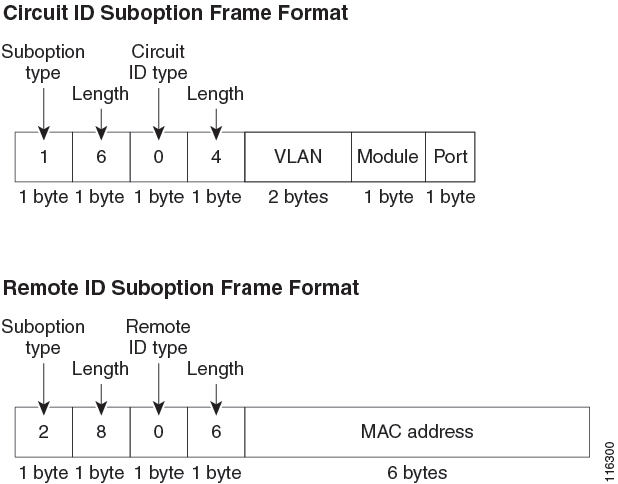
Figure 1. Suboption Packet Formats.

This figure shows the packet formats for the remote ID suboption and the circuit ID suboption. The Cisco NX-OS device uses the packet formats when you globally enable DHCP snooping and when you enable Option 82 data insertion and removal. For the circuit ID suboption, the module field is the slot number of the module.

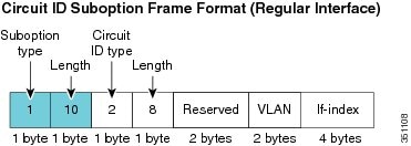
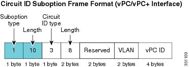
Figure 2. Circuit ID Suboption Frame Format for Regular and vPC Interfaces.

Beginning with Cisco NX-OS Release 6.2(2), a new circuit ID format is used when Option 82 is enabled in DHCP snooping. The new circuit ID format is used by default and cannot be disabled. However, you might need to configure the DHCP server for the new circuit ID format if it was using the old Option 82 format for IP address allocation. These figures show the new default circuit ID format that is used for regular interfaces and vPC interfaces when Option 82 is enabled for DHCP snooping.

The enhanced Option 82 format improves DHCP packet processing. For vPC and vPC+ interfaces, the new format assigns vPC peers a unique circuit ID in case some are configured with different port channel numbers.


Information About the DHCP Relay Agent

DHCP Relay Agent

You can configure the device to run a DHCP relay agent, which forwards DHCP packets between clients and servers. This feature is useful when clients and servers are not on the same physical subnet. Relay agents receive DHCP messages and then generate a new DHCP message to send out on another interface. The relay agent sets the gateway address (giaddr field of the DHCP packet) and, if configured, adds the relay agent information option (Option 82) in the packet and forwards it to the DHCP server. The reply from the server is forwarded back to the client after removing Option 82.

After you enable Option 82, the device uses the binary ifindex format by default. If needed, you can change the Option 82 setting to use an encoded string format instead.


Note


When the device relays a DHCP request that already includes Option 82 information, the device forwards the request with the original Option 82 information without altering it.


DHCP Relay Agent Option 82

You can enable the device to insert and remove Option 82 information on DHCP packets that are forwarded by the relay agent.

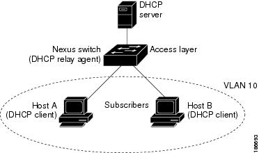
Figure 3. DHCP Relay Agent in a Metropolitan Ethernet Network.

This figure shows an example of a metropolitan Ethernet network in which a centralized DHCP server assigns IP addresses to subscribers connected to the device at the access layer. Because the DHCP clients and their associated DHCP server do not reside on the same IP network or subnet, a DHCP relay agent is configured with a helper address to enable broadcast forwarding and to transfer DHCP messages between the clients and the server.

When you enable Option 82 for the DHCP relay agent on the Cisco NX-OS device, the following sequence of events occurs:

  1. The host (DHCP client) generates a DHCP request and broadcasts it on the network.

  2. When the Cisco NX-OS device receives the DHCP request, it adds the Option 82 information in the packet. The Option 82 information contains the device MAC address (the remote ID suboption) and the port identifier, vlan-mod-port, from which the packet is received (the circuit ID suboption). In DHCP relay, the circuit ID is filled with the if_index of the SVI or Layer 3 interface on which DHCP relay is configured.


    Note


    For vPC peer devices, the remote ID suboption contains the vPC device MAC address, which is unique in both devices. This MAC address is computed with the vPC domain ID. The Option 82 information is inserted at the device where the DHCP request is first received before it is forwarded to the other vPC peer device.


  3. When dhcp relay source interface interface is configured the device adds the configured source interface IP address as giaddr to the DHCP packet if source interface vrf is same as that of DHCP server VRF, otherwise IP address of the interface through which the server is reachable will be used as giaddr.

  4. The device forwards the DHCP request that includes the Option 82 field to the DHCP server.

  5. The DHCP server receives the packet. If the server is Option 82 capable, it can use the remote ID, the circuit ID, or both to assign IP addresses and implement policies, such as restricting the number of IP addresses that can be assigned to a single remote ID or circuit ID. The DHCP server echoes the Option 82 field in the DHCP reply.

  6. The DHCP server unicasts the reply to the Cisco NX-OS device if the request was relayed to the server by the device. The Cisco NX-OS device verifies that it originally inserted the Option 82 data by inspecting the remote ID and possibly the circuit ID fields. The Cisco NX-OS device removes the Option 82 field and forwards the packet to the interface that connects to the DHCP client that sent the DHCP request.

Information About the DHCPv6 Relay Agent

DHCPv6 Relay Agent

You can configure the device to run a DHCPv6 relay agent, which forwards DHCPv6 packets between clients and servers. This feature is useful when clients and servers are not on the same physical subnet. Relay agents receive DHCPv6 messages and then generate a new DHCPv6 message to send out on another interface. The relay agent sets the gateway address (giaddr field of the DHCPv6 packet) and forwards it to the DHCPv6 server.

VRF Support for the DHCPv6 Relay Agent

You can configure the DHCPv6 relay agent to forward DHCPv6 broadcast messages from clients in a virtual routing and forwarding (VRF) instance to DHCPv6 servers in a different VRF. By using a single DHCPv6 server to provide DHCP support to clients in multiple VRFs, you can conserve IP addresses by using a single IP address pool rather than one for each VRF. For general information about VRFs, see the Cisco Nexus 7000 Series NX-OS Unicast Routing Configuration Guide.

Information About the Lightweight DHCPv6 Relay Agent

Lightweight DHCPv6 Relay Agent

A variety of different link-layer network topologies exist for the aggregation of IPv6 nodes into one or more routers. In Layer 2 aggregation networks (IEEE 802.1D bridging or similar) that have many nodes on a single link, a DHCP Version 6 (DHCPv6) server or DHCP relay agent normally does not recognize how a DHCP client is attached to a network. From Cisco NX-OS Release 7.3(0)D1(1), you can configure the interface of a device to run Lightweight DHCPv6 Relay Agent (LDRA), which forwards DHCPv6 messages between clients and servers.

The LDRA feature is used to insert relay agent options in DHCPv6 message exchanges primarily to identify client-facing interfaces. LDRA resides on the same IPv6 link as the client and a DHCPv6 relay agent or server.

LDRA for VLANs and Interfaces

You can configure LDRA on VLANs and interfaces. LDRA is not enabled by default. To enable LDRA, it should be enabled globally and at the interface level. You should configure the interfaces as client-facing trusted, client-facing untrusted, or server-facing. All client-facing interfaces must be configured as trusted or untrusted. By default, all the client-facing interfaces in LDRA are configured as untrusted. When a client-facing interface is deemed untrusted, LDRA will discard messages of type RELAY-FORWARD, which are received from the client-facing interface.

The LDRA configuration on a VLAN should be configured as client-facing trusted or client-facing untrusted. When you configure LDRA functionality on a VLAN, the functionality is configured on all the ports or interfaces within the VLAN. However, if you configure an interface in a VLAN as client-facing untrusted, and configure the VLAN as client-facing trusted, the configuration of an interface takes precedence over the configuration of a VLAN. At least one interface in a VLAN should be configured as server-facing interface.

Guidelines and Limitations for Lightweight DHCPv6 Relay Agent

  • Access nodes implementing LDRA do not support IPv6 control or routing.

  • An interface or port cannot be configured as both client facing and server facing at the same time.

  • To support virtual port channel, LDRA configuration should be symmetric on the vPC peers.

  • LDRA is not supported with DHCP snooping on the same VLAN.

  • LDRA supports Cisco Fabricpath.

  • Upgrading to the Cisco NX-OS Release 8.0(1) with the LDRA feature is not supported. You need to disable the LDRA feature and then upgrade to the Cisco NX-OS Release 8.0(1). You can reconfigure the LDRA feature after upgrade.

Information About the vIP HSRP Enhancement

vIP HSRP Enhancement

The vIP HSRP enhancement provides support for an HSRP VIP configuration to be in a different subnet than that of the interface subnet. This feature is applicable only for IPv4 and not for IPv6. The following are the enhancements:

  • Enhance ARP to source with VIP from SUP for hosts when hosts in VIP subnet are referenced by static route to VLAN configuration.

  • Periodic ARP sync support to VPC peer if this feature enabled.

  • Allow use of the VIP address as L3 source address and gateway address for all communications with DHCP server.

  • Enhance DHCP relay agent to relay DHCP packets with source as VIP instead of SVI IP when the feature is enabled.

Guidelines and Limitations for the vIP HSRP Enhancement

  • This feature will work only for HSRP in combination with VPC topologies. In scenarios where HSRP standby is not a VPC pair, this feature will not work, as there will not be periodic adjacency sync support for non-VPC cases.

  • This feature is applicable only for IPv4 and not for IPv6.

  • Support for this feature is only for Regular HSRP and not for Anycast HSRP, so this feature will not work if Anycast HSRP is enabled.

  • SUP generated IP traffic (for example, ping/traceroute/ICMP Error packets) destined for VIP subnets originated from the HSRP Active/Standby box will continue to source with IPv4 SVI interface IP and not the vIP. If you want to explicitly source using the loopback IP for ping/traceroute, you can specify the loopback IP along with the source keyword.

  • Static ARP configuration for creating entries in VIP subnets is not supported.

  • DHCP relay agent will always use primary VIP address to communicate with DHCP server. DHCP relay agent does not consider use of secondary VIP addresses as long as primary VIP is available.

  • DHCP relay agent behavior in case inter-vrf is different and requires use of Option-82 information in DHCP packets. DHCP server and clients will be in the same VRF and use of VIP is not supported for inter-vrf relay.

  • If you want uRPF and vPC with strict mode, you can use the ip port access-group __urpf_v4_acl__ in command on peer link, VIP with uRPF strict mode. The following example shows the configuration:

    
    interface port-channel10
     switchport            
     switchport mode trunk
     spanning-tree port type network
     ip port access-group __urpf_v4_acl__ in
     vpc peer-link

Information About UDP Relay

UDP Relay

By default, routers do not forward broadcast packets. You should configure routers if you want to forward broadcast packets. From Cisco NX-OS Release 7.3(0)D1(1), you can use the UDP relay feature to relay broadcasts destined for UDP ports except DHCPv4 port numbers 67 and 68. The UDP relay feature is also known as the IP Helper feature.

Enabling UDP Relay

Use the ip forward-protocol udp command to enable the UDP relay feature. By default, the UDP relay feature is disabled. The following UDP ports are enabled by default, when you run the ip forward-protocol udp command:

  • Trivial File Transfer Protocol (TFTP) (port 69)

  • Time service (port 37)

  • NetBIOS Name Server (port 137)

  • NetBIOS Datagram Server (port 138)

  • TACACS service (port 49)

  • IEN-116 Name Service (port 42)

  • Domain Naming System (port 53)

You can also enable or disable the UDP relay feature on other UDP ports within the range 1 to 65535, except DHCPv4 UDP ports 67 and 68.


Note


Enable the DHCP feature before you enable the UDP relay feature.


To forward a packet, configure IP address object groups with the forwarding destination IP addresses or network addresses and then associate the IP address object groups with the L3 interfaces. Subnet broadcast can also be configured for each Layer 3 interface.

The UDP relay feature is supported on the following types of Layer 3 interfaces:

  • Physical port

  • Interface VLAN (SVI)

  • L3 port channel

  • L3 subinterfaces

  • M1 and M2 FEX interfaces

Unlike DHCP relay, UDP broadcast packets are handled on line cards only.

Subnet Broadcast for UDP

By default, UDP forwarding for directed broadcast packets is not enabled on an interface. You can enable the UDP relay feature on a L3 or switch virtual interface (SVI) by using the ip udp relay subnet-broadcast command. When you enable subnet broadcast, all the UDP packets that meet the following criteria are forwarded:

  • The packet must be an IP level-directed broadcast, that is, the primary subnet broadcast or any of the secondary subnet broadcasts for the interface.

  • The destination UDP port number of the packet must be any of the default UDP ports or any other UDP port that is specified by using the ip forward-protocol udp udp-port-num configuration command.

When you enable the subnet broadcast, policies should be updated for the respective L3 or SVI interface.

Guidelines and Limitations for UDP Relay

  • The UDP Relay feature is supported only on the M-series line cards.

  • The maximum number of UDP destination addresses allowed per object group is 300.

  • Any L3 or SVI interface can be associated with a maximum of one object group. Therefore, any interface can be associated with a maximum of 300 UDP relay IP addresses.

  • The UDP relay feature supports a maximum of 200 UDP ports that includes seven default ports.

  • Subnet broadcast is supported for up to two secondary IP addresses of the interface other than the primary address. You can configure any number of secondary IP addresses on the interface, but UDP relay ACL is programmed only for the following:

    • Broadcast address (255.255.255.255)

    • Primary address of the interface

    • Two secondary addresses of an interface

  • The display of statistics per destination is not supported. You can check the ACL TCAM statistics for the policy by using the internal commands.

  • The configuration of separate UDP relay policies on different interfaces depends on the following:

    • Linecards

    • UDP Relay feature enabled on ports

    • Subnet broadcast enabled on L3 or SVI interfaces

Virtualization Support for DHCP

The following information applies to DHCP used in virtual device contexts (VDCs):

  • DHCP snooping binding databases are unique per VDC. Bindings in one VDC do not affect DHCP snooping in other VDCs.

  • The system does not limit the binding database size on a per-VDC basis.

  • The DHCP smart relay agent can be configured independently in default and nondefault VDCs.

Prerequisites for DHCP

DHCP has the following prerequisite:

  • You should be familiar with DHCP before you configure DHCP snooping or the DHCP relay agent.

Guidelines and Limitations for DHCP

DHCP has the following configuration guidelines and limitations:

  • If you are using both the Unicast reverse Packeting Forwarding (uRFP) strict mode in your client vPC VLANs and the First Hop Redundancy Protocol (FHRP) with the DHCP relay feature, the DHCP requests are sourced from the physical egress IP address interface (not the FHRP VIP) by default. Consequently, if your DHCP server is not on a directly connected subnet and you have multiple ECMP routes back to your vPC pair, some packets might land on the neighbor switch instead of the originating switch and be dropped by RFP. This behavior is expected. To avoid this scenario, perform one of the following workarounds:
    • Use the uRFP loose mode, not uRFP strict.

    • Configure static routes for the interface address on the affected FHRP interfaces and redistribute the static routes into IGP.

  • Using the ip dhcp relay source-interface interface-name command, you can configure a different interface as the source interface. This command is used for DHCP relay in VPN and in non-VPN environments. The dhcp relay information option with vpn sub-option must be enabled for this command configuration to work. To enable VRF support for the DHCP relay agent, use the ip dhcp relay information option vpn command. For more details about the ip dhcp relay information option vpn command, see the Cisco Nexus 7000 Series Security Command Reference.

  • For Cisco NX-OS Release 6.2 and later releases, you must enable the insertion of Option 82 information for DHCP packets to support the highest DHCP snooping scale.

  • After System Switchover, DHCP Global stats show incorrect values as they are not stored in PSS and get erased. Updating stats in PSS during packet path will affect scale.

  • If you use DHCP relay where DHCP clients and servers are in different VRF instances, use only one DHCP server within a VRF.

  • Before globally enabling DHCP snooping on the device, make sure that the devices acting as the DHCP server and the DHCP relay agent are configured and enabled.

  • DHCP snooping does not work with DHCP relay configured on the same nexus device.

  • If a VLAN ACL (VACL) is configured on a VLAN that you are configuring with DHCP snooping, ensure that the VACL permits DHCP traffic between DHCP servers and DHCP hosts. When both DHCP snooping and DHCP relay are enabled on a VLAN and the SVI of that VLAN, DHCP relay takes precedence.

  • If an ingress router ACL is configured on a Layer 3 interface that you are configuring with a DHCP server address, ensure that the router ACL permits DHCP traffic between DHCP servers and DHCP hosts.

  • Access-control list (ACL) statistics are not supported if the DHCP snooping feature is enabled.

  • Before using POAP, make sure that DHCP snooping is enabled and firewall rules are set to block unintended or malicious DHCP servers.

  • When you configure DHCPv6 server addresses on an interface, a destination interface cannot be used with global IPv6 addresses.


Note


For DHCP configuration limits, see the Cisco Nexus 7000 Series NX-OS Verified Scalability Guide.


Default Settings for DHCP

This table lists the default settings for DHCP parameters.

Table 1. Default DHCP Parameters

Parameters

Default

DHCP feature

Disabled

DHCP snooping

Disabled

DHCP snooping on VLANs

Disabled

DHCP snooping MAC address verification

Enabled

DHCP snooping Option 82 support

Disabled

DHCP snooping trust

Untrusted

DHCP relay agent

Enabled

DHCPv6 relay agent

Enabled

Lightweight DHCPv6 Relay Agent

Disabled

UDP Relay feature

Disabled

VRF support for the DHCP relay agent

Disabled

VRF support for the DHCPv6 relay agent

Disabled

DHCP relay sub-option type cisco

Disabled

DHCPv6 relay option type cisco

Disabled

DHCP Option 82 for relay agent

Disabled

DHCP server IP address

None

Configuring DHCP

Minimum DHCP Configuration

Procedure


Step 1

Enable the DHCP feature.

When the DHCP feature is disabled, you cannot configure DHCP snooping.

Step 2

Enable DHCP snooping globally.

Step 3

Enable DHCP snooping on at least one VLAN.

By default, DHCP snooping is disabled on all VLANs.

Step 4

Ensure that the DHCP server is connected to the device using a trusted interface.

Step 5

(Optional) Configure an interface with the IP address of the DHCP server.


Enabling or Disabling the DHCP Feature

You can enable or disable the DHCP feature on the device. By default, DHCP is disabled.

When the DHCP feature is disabled, you cannot configure DHCP snooping, the DHCP relay agent, or any of the features that depend on DHCP, such as dynamic ARP inspection and IP Source Guard. In addition, all DHCP, dynamic ARP inspection, and IP Source Guard configuration is removed from the device.

SUMMARY STEPS

  1. config t
  2. [no] feature dhcp
  3. (Optional) show running-config dhcp
  4. (Optional) copy running-config startup-config

DETAILED STEPS

  Command or Action Purpose

Step 1

config t

Example:

switch# config t
switch(config)#

Enters global configuration mode.

Step 2

[no] feature dhcp

Example:

switch(config)# feature dhcp

Enables the DHCP feature. The no option disables the DHCP feature and erases all DHCP configuration.

Step 3

(Optional) show running-config dhcp

Example:

switch(config)# show running-config dhcp
(Optional)

Displays the DHCP configuration.

Step 4

(Optional) copy running-config startup-config

Example:

switch(config)# copy running-config startup-config
(Optional)

Copies the running configuration to the startup configuration.

Enabling or Disabling DHCP Snooping Globally

You can enable or disable DHCP snooping globally on the device.

Before you begin

Ensure that you have enabled the DHCP feature.

SUMMARY STEPS

  1. config t
  2. [no] ip dhcp snooping
  3. (Optional) show running-config dhcp
  4. (Optional) copy running-config startup-config

DETAILED STEPS

  Command or Action Purpose

Step 1

config t

Example:

switch# config t
switch(config)#

Enters global configuration mode.

Step 2

[no] ip dhcp snooping

Example:

switch(config)# ip dhcp snooping

Enables DHCP snooping globally. The no option disables DHCP snooping.

Step 3

(Optional) show running-config dhcp

Example:

switch(config)# show running-config dhcp
(Optional)

Displays the DHCP configuration.

Step 4

(Optional) copy running-config startup-config

Example:

switch(config)# copy running-config startup-config
(Optional)

Copies the running configuration to the startup configuration.

Enabling or Disabling DHCP Snooping on a VLAN

You can enable or disable DHCP snooping on one or more VLANs. By default, DHCP snooping is disabled on all VLANs.

Before you begin

Ensure that the DHCP feature is enabled.


Note


If a VACL is configured on a VLAN that you are configuring with DHCP snooping, ensure that the VACL permits DHCP traffic between DHCP servers and DHCP hosts.


SUMMARY STEPS

  1. config t
  2. [no] ip dhcp snooping vlan vlan-list
  3. (Optional) show running-config dhcp
  4. (Optional) copy running-config startup-config

DETAILED STEPS

  Command or Action Purpose

Step 1

config t

Example:

switch# config t
switch(config)#

Enters global configuration mode.

Step 2

[no] ip dhcp snooping vlan vlan-list

Example:

switch(config)# ip dhcp snooping vlan 100,200,250-252

Enables DHCP snooping on the VLANs specified by vlan-list . The no option disables DHCP snooping on the VLANs specified.

Step 3

(Optional) show running-config dhcp

Example:

switch(config)# show running-config dhcp
(Optional)

Displays the DHCP configuration.

Step 4

(Optional) copy running-config startup-config

Example:

switch(config)# copy running-config startup-config
(Optional)

Copies the running configuration to the startup configuration.

Enabling or Disabling DHCP Snooping MAC Address Verification

You can enable or disable DHCP snooping MAC address verification. If the device receives a packet on an untrusted interface and the source MAC address and the DHCP client hardware address do not match, address verification causes the device to drop the packet. MAC address verification is enabled by default.

Before you begin

Ensure that the DHCP feature is enabled.

SUMMARY STEPS

  1. config t
  2. [no] ip dhcp snooping verify mac-address
  3. (Optional) show running-config dhcp
  4. (Optional) copy running-config startup-config

DETAILED STEPS

  Command or Action Purpose

Step 1

config t

Example:

switch# config t
switch(config)#

Enters global configuration mode.

Step 2

[no] ip dhcp snooping verify mac-address

Example:

switch(config)# ip dhcp snooping verify mac-address

Enables DHCP snooping MAC address verification. The no option disables MAC address verification.

Step 3

(Optional) show running-config dhcp

Example:

switch(config)# show running-config dhcp
(Optional)

Displays the DHCP configuration.

Step 4

(Optional) copy running-config startup-config

Example:

switch(config)# copy running-config startup-config
(Optional)

Copies the running configuration to the startup configuration.

Enabling or Disabling Option 82 Data Insertion and Removal

You can enable or disable the insertion and removal of Option 82 information for DHCP packets forwarded without the use of the DHCP relay agent. By default, the device does not include Option 82 information in DHCP packets.


Note


DHCP relay agent support for Option 82 is configured separately.


Note


To support a higher DHCP pps scale, you must enable the insertion of Option 82 information for DHCP packets.


Before you begin

Ensure that the DHCP feature is enabled.

SUMMARY STEPS

  1. config t
  2. [no] ip dhcp snooping information option
  3. (Optional) show running-config dhcp
  4. (Optional) copy running-config startup-config

DETAILED STEPS

  Command or Action Purpose

Step 1

config t

Example:

switch# config t
switch(config)#

Enters global configuration mode.

Step 2

[no] ip dhcp snooping information option

Example:

switch(config)# ip dhcp snooping information option

Enables the insertion and removal of Option 82 information for DHCP packets. The no option disables the insertion and removal of Option 82 information.

Step 3

(Optional) show running-config dhcp

Example:

switch(config)# show running-config dhcp
(Optional)

Displays the DHCP configuration.

Step 4

(Optional) copy running-config startup-config

Example:

switch(config)# copy running-config startup-config
(Optional)

Copies the running configuration to the startup configuration.

Configuring an Interface as Trusted or Untrusted

You can configure whether an interface is a trusted or untrusted source of DHCP messages. By default, all interfaces are untrusted. You can configure DHCP trust on the following types of interfaces:

  • Layer 2 Ethernet interfaces

  • Layer 2 port-channel interfaces

Before you begin

Ensure that the DHCP feature is enabled.

Ensure that the interface is configured as a Layer 2 interface.

SUMMARY STEPS

  1. config t
  2. Do one of the following options:
    • interface ethernet slot/port
    • interface port-channel channel-number
  3. [no] ip dhcp snooping trust
  4. (Optional) show running-config dhcp
  5. (Optional) copy running-config startup-config

DETAILED STEPS

  Command or Action Purpose

Step 1

config t

Example:

switch# config t
switch(config)#

Enters global configuration mode.

Step 2

Do one of the following options:

  • interface ethernet slot/port
  • interface port-channel channel-number

Example:

switch(config)# interface ethernet 2/1
switch(config-if)#
  • Enters interface configuration mode, where slot /port is the Layer 2 Ethernet interface that you want to configure as trusted or untrusted for DHCP snooping.

  • Enters interface configuration mode, where slot /port is the Layer 2 port-channel interface that you want to configure as trusted or untrusted for DHCP snooping.

Step 3

[no] ip dhcp snooping trust

Example:

switch(config-if)# ip dhcp snooping trust

Configures the interface as a trusted interface for DHCP snooping. The no option configures the port as an untrusted interface.

Step 4

(Optional) show running-config dhcp

Example:

switch(config-if)# show running-config dhcp
(Optional)

Displays the DHCP configuration.

Step 5

(Optional) copy running-config startup-config

Example:

switch(config-if)# copy running-config startup-config
(Optional)

Copies the running configuration to the startup configuration.

Enabling or Disabling DHCP Relay Trusted Port Functionality

You can enable or disable the DHCP relay trusted port functionality. By default, if the gateway address is set to all zeros in the DHCP packet and the relay information option is already present in the packet, the DHCP relay agent will not discard the packet. If the ip dhcp relay information option trust command is configured globally, the DHCP relay agent will discard the packet if the gateway address is set to all zeros.

Before you begin

Ensure that the DHCP feature is enabled.

SUMMARY STEPS

  1. config t
  2. [no] ip dhcp relay information option trust
  3. (Optional) show ip dhcp relay
  4. (Optional) show ip dhcp relay information trusted-sources
  5. (Optional) show running-config dhcp
  6. (Optional) copy running-config startup-config

DETAILED STEPS

  Command or Action Purpose

Step 1

config t

Example:

switch# config terminal
switch(config)#

Enters global configuration mode.

Step 2

[no] ip dhcp relay information option trust

Example:

switch(config)# ip dhcp relay information option trust

Enables the DHCP relay trusted port functionality. The no option disables this functionality.

Step 3

(Optional) show ip dhcp relay

Example:

switch(config)# show ip dhcp relay
(Optional)

Displays the DHCP relay configuration.

Step 4

(Optional) show ip dhcp relay information trusted-sources

Example:

switch(config)# show ip dhcp relay information trusted-sources
(Optional)

Displays the DHCP relay trusted ports configuration.

Step 5

(Optional) show running-config dhcp

Example:

switch(config)# show running-config dhcp
(Optional)

Displays the DHCP configuration.

Step 6

(Optional) copy running-config startup-config

Example:

switch(config)# copy running-config startup-config
(Optional)

Copies the running configuration to the startup configuration.

Configuring an Interface as a DHCP Relay Trusted or Untrusted Port

You can configure whether a Layer 3 interface is a DHCP relay trusted or untrusted interface. By default, all interfaces are untrusted. You can configure DHCP relay trust on the following types of interfaces:

  • Layer 3 Ethernet interfaces and sub-interfaces

  • Layer 3 port-channel interfaces

  • Interface VLAN

Before you begin

Ensure that the DHCP feature is enabled.

SUMMARY STEPS

  1. config t
  2. Do one of the following options:
    • interface ethernet slot/port.[number]
    • interface port-channel channel-number.[subchannel-id]
    • interface vlan vlan-id
  3. [no] ip dhcp relay information trusted
  4. show ip dhcp relay information trusted-sources
  5. (Optional) show running-config dhcp
  6. (Optional) copy running-config startup-config

DETAILED STEPS

  Command or Action Purpose

Step 1

config t

Example:

switch# config t
switch(config)#

Enters global configuration mode.

Step 2

Do one of the following options:

  • interface ethernet slot/port.[number]
  • interface port-channel channel-number.[subchannel-id]
  • interface vlan vlan-id

Example:

switch(config)# interface ethernet 2/1
switch(config-if)#
  • Enters interface configuration mode, where slot /port is the Layer 3 Ethernet interface that you want to configure as trusted or untrusted.

  • Enters interface configuration mode, where channel-number is the Layer 3 port-channel interface that you want to configure as trusted or untrusted.

  • Enters interface configuration mode, where vlan-id is the VLAN interface that you want to configure as trusted or untrusted.

Step 3

[no] ip dhcp relay information trusted

Example:

switch(config-if)# ip dhcp relay information trusted

Configures the interface as a trusted interface for DHCP relay agent information. The no option configures the port as an untrusted interface.

Note


For any L3 interface, if the interface is configured as trusted either through global command or interface-level command, the interface is considered as a trusted interface. Hence, when the trusted-port command is enabled at Global level, any L3 interface cannot be considered as untrusted irrespective of the interface-level configuration.

Step 4

show ip dhcp relay information trusted-sources

Example:

switch(config-if)# show ip dhcp relay information trusted-sources

Displays the DHCP relay trusted ports configuration.

Step 5

(Optional) show running-config dhcp

Example:

switch(config-if)# show running-config dhcp
(Optional)

Displays the DHCP configuration.

Step 6

(Optional) copy running-config startup-config

Example:

switch(config-if)# copy running-config startup-config
(Optional)

Copies the running configuration to the startup configuration.

Configuring all Interfaces as Trusted or Untrusted

You can configure all Layer 3 interfaces as DHCP relay trusted or untrusted interfaces. By default, all interfaces are untrusted. You can configure DHCP relay trust on the following types of interfaces:

  • Layer 3 Ethernet interfaces and sub-interfaces

  • Layer 3 port-channel interfaces

  • Interface VLAN

When you enable the ip dhcp relay information trust-all command, any Layer 3 interface cannot be considered as untrusted irrespective of the interface-level configuration.

Before you begin

Ensure that the DHCP feature is enabled.

SUMMARY STEPS

  1. config t
  2. [no] ip dhcp relay information trust-all
  3. show ip dhcp relay information trusted-sources
  4. (Optional) show running-config dhcp
  5. (Optional) copy running-config startup-config

DETAILED STEPS

  Command or Action Purpose

Step 1

config t

Example:

switch# config t
switch(config)#

Enters global configuration mode.

Step 2

[no] ip dhcp relay information trust-all

Example:

switch(config)# ip dhcp relay information trust-all

Configures the interfaces as trusted sources of DHCP messages. The no option configures the ports as untrusted interfaces.

Step 3

show ip dhcp relay information trusted-sources

Example:

switch(config)# show ip dhcp relay information trusted-sources

Displays the DHCP relay trusted ports configuration.

Step 4

(Optional) show running-config dhcp

Example:

switch(config)# show running-config dhcp
(Optional)

Displays the DHCP configuration.

Step 5

(Optional) copy running-config startup-config

Example:

switch(config)# copy running-config startup-config
(Optional)

Copies the running configuration to the startup configuration.

Enabling or Disabling the DHCP Relay Agent

You can enable or disable the DHCP relay agent. By default, the DHCP relay agent is enabled.

Before you begin

Ensure that the DHCP feature is enabled.

SUMMARY STEPS

  1. config t
  2. [no] ip dhcp relay
  3. (Optional) show ip dhcp relay
  4. (Optional) show running-config dhcp
  5. (Optional) copy running-config startup-config

DETAILED STEPS

  Command or Action Purpose

Step 1

config t

Example:

switch# config t
switch(config)#

Enters global configuration mode.

Step 2

[no] ip dhcp relay

Example:

switch(config)# ip dhcp relay

Enables the DHCP relay agent. The no option disables the relay agent.

Step 3

(Optional) show ip dhcp relay

Example:

switch(config)# show ip dhcp relay
(Optional)

Displays the DHCP relay configuration.

Step 4

(Optional) show running-config dhcp

Example:

switch(config)# show running-config dhcp
(Optional)

Displays the DHCP configuration.

Step 5

(Optional) copy running-config startup-config

Example:

switch(config)# copy running-config startup-config
(Optional)

Copies the running configuration to the startup configuration.

Enabling or Disabling the DHCP Relay Source Interface

You can enable or disable the DHCP relay source interface. You can configure a different interface as the source of the DHCP relay agent.

Before you begin

Ensure that the DHCP feature is enabled.

SUMMARY STEPS

  1. configure terminal
  2. [no] ip dhcp relay source-interface interface-name
  3. [no] ip dhcp relay information option vpn
  4. interface interface-name
  5. [no] ip dhcp relay address ip address use-vrf vrf-name
  6. (Optional) show ip dhcp relay source-interface
  7. (Optional) show running-config dhcp
  8. (Optional) copy running-config startup-config

DETAILED STEPS

  Command or Action Purpose

Step 1

configure terminal

Example:

switch# configure terminal
switch(config)#

Enters global configuration mode.

Step 2

[no] ip dhcp relay source-interface interface-name

Example:

switch(config)# ip dhcp relay source-interface Ethernet1/1

Enables the DHCP relay source interface. You can configure a different interface as the source of the DHCP relay agent. The no option disables the relay source interface.

The source interface’s IP address will be used as the source address in the DHCP packet, only when the source interface and the DHCP server are in the same VRF. If not in same VRF, IP address of any other interface (through which server will be reachable) will be used.

Step 3

[no] ip dhcp relay information option vpn

Example:

switch(config)# ip dhcp relay information option vpn

Enables VRF support for the DHCP relay agent. The no option disables the VRF support.

The VPN option will be added in option-82 only when the server and the client are in the different VRF.

Three sub-options get added in the information option of the relayed packet only when the server and client are in different VRFs.

Sub-option 151 - VRF Name / VPN ID: this indicates the VRF information of the client.

Sub-option 11 - Server ID override: this indicates the client subnet gateway.

Sub-option 5 - Link Selection: provides the client subnet address.

When the client and server are in different VRFs, the DHCP server address configuration must have use-vrf vrf-name for the DHCP relay to work.

Step 4

interface interface-name

Example:

switch(config)# interface ethernet 1/3

Configures the interface and enters interface configuration mode.

Step 5

[no] ip dhcp relay address ip address use-vrf vrf-name

Example:

switch(config-if)# ip dhcp relay address 10.43.87.132 use-vrf testA

Configures an IP address for a DHCP server to which the relay agent forwards the packets received on this interface.

The use-vrf option specifies the virtual routing and forwarding instance (VRF) that the DHCP server is within, where the vrf-name argument is the name of the VRF. The VRF membership of the interface connected to the DHCP server determines the VRF that the DHCP is within.

The source interface’s IP address will be used as the source address only when the source interface and the server are in the same VRF.

Step 6

(Optional) show ip dhcp relay source-interface

Example:

switch(config)# show ip dhcp relay source-interface
(Optional)

Displays the DHCP relay source-interface configuration.

Step 7

(Optional) show running-config dhcp

Example:

switch(config)# show running-config dhcp
(Optional)

Displays the DHCP configuration.

Step 8

(Optional) copy running-config startup-config

Example:

switch(config)# copy running-config startup-config
(Optional)

Copies the running configuration to the startup configuration.

Enabling or Disabling Option 82 for the DHCP Relay Agent

You can enable or disable the device to insert and remove Option 82 information on DHCP packets forwarded by the relay agent.

By default, the DHCP relay agent does not include Option 82 information in DHCP packets.

SUMMARY STEPS

  1. configure terminal
  2. [no] ip dhcp relay
  3. [no] ip dhcp relay information option
  4. (Optional) show ip dhcp relay
  5. (Optional) show running-config dhcp
  6. (Optional) copy running-config startup-config

DETAILED STEPS

  Command or Action Purpose

Step 1

configure terminal

Example:

switch# configure terminal
switch(config)#

Enters global configuration mode.

Step 2

[no] ip dhcp relay

Example:

switch(config)# ip dhcp relay

Enables the DHCP relay feature. The no option disables this behavior.

Step 3

[no] ip dhcp relay information option

Example:

switch(config)# ip dhcp relay information option

Enables the DHCP relay agent to insert and remove Option 82 information on the packets that it forwards. The Option 82 information is in binary ifindex format by default. The no option disables this behavior.

Step 4

(Optional) show ip dhcp relay

Example:

switch(config)# show ip dhcp relay
(Optional)

Displays the DHCP relay configuration.

Step 5

(Optional) show running-config dhcp

Example:

switch(config)# show running-config dhcp
(Optional)

Displays the DHCP configuration.

Step 6

(Optional) copy running-config startup-config

Example:

switch(config)# copy running-config startup-config
(Optional)

Saves the change persistently through reboots and restarts by copying the running configuration to the startup configuration.

Configuring DHCP Server Addresses on an Interface

You can configure DHCP server IP addresses on an interface. When an inbound DHCP BOOTREQUEST packet arrives on the interface, the relay agent forwards the packet to all DHCP server IP addresses specified. The relay agent forwards replies from all DHCP servers to the host that sent the request.

Before you begin

Ensure that the DHCP feature is enabled.

Ensure that the DHCP server is correctly configured.

Determine the IP address for each DHCP server that you want to configure on the interface.

If the DHCP server is in a different VRF instance than the interface, ensure that you have enabled VRF support.


Note


If an ingress router ACL is configured on an interface that you are configuring with a DHCP server address, ensure that the router ACL permits DHCP traffic between DHCP servers and DHCP hosts.


SUMMARY STEPS

  1. config t
  2. Do one of the following options:
    • interface ethernet slot/port[. number]
    • interface vlan vlan-id
    • interface port-channel channel-id[.subchannel-id]
  3. ip dhcp relay address IP-address
  4. (Optional) show ip dhcp relay address
  5. (Optional) show running-config dhcp
  6. (Optional) copy running-config startup-config

DETAILED STEPS

  Command or Action Purpose

Step 1

config t

Example:

switch# config t
switch(config)#

Enters global configuration mode.

Step 2

Do one of the following options:

  • interface ethernet slot/port[. number]
  • interface vlan vlan-id
  • interface port-channel channel-id[.subchannel-id]

Example:

switch(config)# interface ethernet 2/3
switch(config-if)#
  • Enters interface configuration mode, where slot /port is the physical Ethernet interface that you want to configure with a DHCP server IP address. If you want to configure a subinterface, include the number argument to specify the subinterface number.

  • Enters interface configuration mode, where vlan-id is the ID of the VLAN that you want to configure with a DHCP server IP address.

  • Enters interface configuration mode, where channel-id is the ID of the port channel that you want to configure with a DHCP server IP address. If you want to configure a subchannel, include the subchannel-id argument to specify the subchannel ID.

Step 3

ip dhcp relay address IP-address

Example:

switch(config-if)# ip dhcp relay address 10.132.7.120

Configures an IP address for a DHCP server to which the relay agent forwards BOOTREQUEST packets received on this interface.

To configure more than one IP address, use the ip dhcp relay address command once per address.

Step 4

(Optional) show ip dhcp relay address

Example:

switch(config-if)# show ip dhcp relay address
(Optional)

Displays all the configured DHCP server addresses.

Step 5

(Optional) show running-config dhcp

Example:

switch(config-if)# show running-config dhcp
(Optional)

Displays the DHCP configuration.

Step 6

(Optional) copy running-config startup-config

Example:

switch(config-if)# copy running-config startup-config
(Optional)

Copies the running configuration to the startup configuration.

Configuring DHCPv6

Enabling or Disabling the DHCPv6 Relay Agent

You can enable or disable the DHCPv6 relay agent. By default, the DHCPv6 relay agent is enabled.

Before you begin

Ensure that the DHCP feature is enabled.

SUMMARY STEPS

  1. configure terminal
  2. [no] ipv6 dhcp relay
  3. (Optional) show ipv6 dhcp relay [interface interface]
  4. (Optional) show running-config dhcp
  5. (Optional) copy running-config startup-config

DETAILED STEPS

  Command or Action Purpose

Step 1

configure terminal

Example:

switch# configure terminal
switch(config)#

Enters global configuration mode.

Step 2

[no] ipv6 dhcp relay

Example:

switch(config)# ipv6 dhcp relay

Enables the DHCPv6 relay agent. The no option disables the relay agent.

Step 3

(Optional) show ipv6 dhcp relay [interface interface]

Example:

switch(config)# show ipv6 dhcp relay
(Optional)

Displays the DHCPv6 relay configuration.

Step 4

(Optional) show running-config dhcp

Example:

switch(config)# show running-config dhcp
(Optional)

Displays the DHCP configuration.

Step 5

(Optional) copy running-config startup-config

Example:

switch(config)# copy running-config startup-config
(Optional)

Copies the running configuration to the startup configuration.

Enabling or Disabling VRF Support for the DHCPv6 Relay Agent

You can configure the device to support the relaying of DHCPv6 requests that arrive on an interface in one VRF to a DHCPv6 server in a different VRF.

Before you begin

Ensure that the DHCP feature is enabled.

Ensure that the DHCPv6 relay agent is enabled.

SUMMARY STEPS

  1. configure terminal
  2. [no] ipv6 dhcp relay option vpn
  3. [no] ipv6 dhcp relay option type cisco
  4. (Optional) show ipv6 dhcp relay [interface interface]
  5. (Optional) show running-config dhcp
  6. (Optional) copy running-config startup-config

DETAILED STEPS

  Command or Action Purpose

Step 1

configure terminal

Example:

switch# configure terminal
switch(config)#

Enters global configuration mode.

Step 2

[no] ipv6 dhcp relay option vpn

Example:

switch(config)# ipv6 dhcp relay option vpn

Enables VRF support for the DHCPv6 relay agent. The no option disables this behavior.

Step 3

[no] ipv6 dhcp relay option type cisco

Example:

switch(config)# ipv6 dhcp relay option type cisco

Causes the DHCPv6 relay agent to insert virtual subnet selection (VSS) details as part of the vendor-specific option. The no option causes the DHCPv6 relay agent to insert VSS details as part of the VSS option (68), which is defined in RFC-6607. This command is useful when you want to use DHCPv6 servers that do not support RFC-6607 but allocate IPv6 addresses based on the client VRF name.

Step 4

(Optional) show ipv6 dhcp relay [interface interface]

Example:

switch(config)# show ipv6 dhcp relay
(Optional)

Displays the DHCPv6 relay configuration.

Step 5

(Optional) show running-config dhcp

Example:

switch(config)# show running-config dhcp
(Optional)

Displays the DHCP configuration.

Step 6

(Optional) copy running-config startup-config

Example:

switch(config)# copy running-config startup-config
(Optional)

Copies the running configuration to the startup configuration.

Configuring DHCPv6 Server Addresses on an Interface

You can configure DHCPv6 server IP addresses on an interface. When an inbound DHCP BOOTREQUEST packet arrives on the interface, the relay agent forwards the packet to all DHCPv6 server IP addresses specified. The relay agent forwards replies from all DHCPv6 servers to the host that sent the request.

Before you begin

Ensure that the DHCP feature is enabled.

Ensure that the DHCPv6 server is correctly configured.

Determine the IP address for each DHCPv6 server that you want to configure on the interface.

If the DHCPv6 server is in a different VRF than the interface, ensure that you have enabled VRF support.


Note


If an ingress router ACL is configured on an interface that you are configuring with a DHCPv6 server address, ensure that the router ACL permits DHCP traffic between DHCPv6 servers and DHCP hosts.


SUMMARY STEPS

  1. config t
  2. Do one of the following options:
    • interface ethernet slot/port[. number]
    • interface port-channel channel-id[.subchannel-id]
  3. [no] ipv6 dhcp relay address IPv6-address
  4. (Optional) show running-config dhcp
  5. (Optional) copy running-config startup-config

DETAILED STEPS

  Command or Action Purpose

Step 1

config t

Example:

switch# config t
switch(config)#

Enters global configuration mode.

Step 2

Do one of the following options:

  • interface ethernet slot/port[. number]
  • interface port-channel channel-id[.subchannel-id]

Example:

switch(config)# interface ethernet 2/3
switch(config-if)#
  • Enters interface configuration mode, where slot /port is the physical Ethernet interface that you want to configure with a DHCPv6 server IP address. If you want to configure a subinterface, include the number argument to specify the subinterface number.

  • Enters interface configuration mode, where channel-id is the ID of the port channel that you want to configure with a DHCPv6 server IP address. If you want to configure a subchannel, include the subchannel-id argument to specify the subchannel ID.

Step 3

[no] ipv6 dhcp relay address IPv6-address

Example:

switch(config-if)# ipv6 dhcp relay address FF02:1::FF0E:8C6C 

Configures an IP address for a DHCPv6 server to which the relay agent forwards BOOTREQUEST packets received on this interface.

Use the use-vrf option to specify the VRF name of the server if it is in a different VRF and the other argument interface is used to specify the output interface for the destination.

The server address can either be a link-scoped unicast or multicast address or a global or site-local unicast or multicast address. The interface option is mandatory for a link-scoped server address and multicast address. It is not allowed for a global or site-scoped server address.

To configure more than one IP address, use the ipv6 dhcp relay address command once per address.

Step 4

(Optional) show running-config dhcp

Example:

switch(config-if)# show running-config dhcp
(Optional)

Displays the DHCPv6 configuration.

Step 5

(Optional) copy running-config startup-config

Example:

switch(config-if)# copy running-config startup-config
(Optional)

Copies the running configuration to the startup configuration.

Configuring the DHCPv6 Relay Source Interface

You can configure the source interface for the DHCPv6 relay agent. By default, the DHCPv6 relay agent uses the relay agent address as the source address of the outgoing packet. Configuring the source interface enables you to use a more stable address (such as the loopback interface address) as the source address of relayed messages.

Before you begin

Ensure that the DHCP feature is enabled.

Ensure that the DHCPv6 relay agent is enabled.

SUMMARY STEPS

  1. configure terminal
  2. [no] ipv6 dhcp relay source-interface interface
  3. (Optional) show ipv6 dhcp relay [interface interface]
  4. (Optional) show running-config dhcp
  5. (Optional) copy running-config startup-config

DETAILED STEPS

  Command or Action Purpose

Step 1

configure terminal

Example:

switch# configure terminal
switch(config)#

Enters global configuration mode.

Step 2

[no] ipv6 dhcp relay source-interface interface

Example:

switch(config)# ipv6 dhcp relay source-interface loopback 2

Configures the source interface for the DHCPv6 relay agent.

Note


The DHCPv6 relay source interface can be configured globally, per interface, or both. When both the global and interface levels are configured, the interface-level configuration overrides the global configuration.

Step 3

(Optional) show ipv6 dhcp relay [interface interface]

Example:

switch(config)# show ipv6 dhcp relay
(Optional)

Displays the DHCPv6 relay configuration.

Step 4

(Optional) show running-config dhcp

Example:

switch(config)# show running-config dhcp
(Optional)

Displays the DHCP configuration.

Step 5

(Optional) copy running-config startup-config

Example:

switch(config)# copy running-config startup-config
(Optional)

Copies the running configuration to the startup configuration.

Configuring Lightweight DHCPv6 Relay Agent

Configuring Lightweight DHCPv6 Relay Agent for an Interface

Perform this task to configure Lightweight DHCPv6 Relay Agent (LDRA) for an interface.

SUMMARY STEPS

  1. configure terminal
  2. [no] ipv6 dhcp-ldra
  3. interface slot/port
  4. switchport
  5. [no] ipv6 dhcp-ldra {client-facing-trusted | client-facing-untrusted | client-facing-disable | server-facing}

DETAILED STEPS

  Command or Action Purpose

Step 1

configure terminal

Example:


switch# configure terminal

Enters global configuration mode.

Step 2

[no] ipv6 dhcp-ldra

Example:


switch(config)# ipv6 dhcp-ldra

Enables the LDRA functionality globally.

Step 3

interface slot/port

Example:


switch(config)# interface ethernet 0/0

Specifies an interface type and number, and enters interface configuration mode.

Step 4

switchport

Example:


switch(config-if)# switchport

Switches an interface that is in Layer 3 mode to Layer 2 mode for Layer 2 configuration.

Step 5

[no] ipv6 dhcp-ldra {client-facing-trusted | client-facing-untrusted | client-facing-disable | server-facing}

Example:


switch(config-if)# ipv6 dhcp-ldra server-facing

Enables LDRA functionality on a specified interface or port. The no option disables the LDRA functionality.

Note


The client-facing-trusted specifies client-facing interfaces or ports as trusted. The trusted port allows the DHCPv6 packets and they are encapsulated as per LDRA options. The client-facing-untrusted specifies client-facing interfaces or ports as untrusted. The untrusted ports perform LDRA functionality, but drop only the relay forward packets received on it. The client-facing-disable keyword disables LDRA functionality on an interface or port. Disabled port performs the Layer-2 forwarding of DHCPv6 packets. The server-facing keyword specifies an interface or port as server facing. Server facing port allows the reply packets from server.

Configuring Lightweight DHCPv6 Relay Agent for a VLAN

Perform this task to configure Lightweight DHCPv6 Relay Agent (LDRA) for a VLAN.

Before you begin

Ensure that the VLAN is not assigned an IP address.

SUMMARY STEPS

  1. configure terminal
  2. [no] ipv6 dhcp-ldra
  3. [no] ipv6 dhcp-ldra attach–policy vlan vlan-id {client-facing-trusted | client-facing-untrusted}

DETAILED STEPS

  Command or Action Purpose

Step 1

configure terminal

Example:


switch# configure terminal

Enters global configuration mode.

Step 2

[no] ipv6 dhcp-ldra

Example:


switch(config)# ipv6 dhcp-ldra

Enables the LDRA functionality globally.

Step 3

[no] ipv6 dhcp-ldra attach–policy vlan vlan-id {client-facing-trusted | client-facing-untrusted}

Example:


switch(config)# ipv6 dhcp-ldra attach-policy vlan 25 client-facing-trusted

Enables LDRA functionality on the specified VLAN. The no option disables the LDRA functionality.

Note


The client-facing-trusted keyword configures all the ports or interfaces associated with the VLAN as client-facing, trusted ports. The client-facing-untrusted keyword configures all the ports or interfaces associated with the VLAN as client-facing, untrusted ports.

Enabling DHCP Relay Agent using VIP Address

SUMMARY STEPS

  1. switch# configure terminal
  2. switch(config)# [no] ip dhcp relay source-address hsrp
  3. switch(config)# interface type number
  4. switch(config-if)# [no] ip dhcp relay source-address hsrp
  5. switch(config-if)# end
  6. (Optional) switch# show ip dhcp relay
  7. (Optional) switch# show hsrp brief

DETAILED STEPS

  Command or Action Purpose

Step 1

switch# configure terminal

Enters global configuration mode

Step 2

switch(config)# [no] ip dhcp relay source-address hsrp

Enables/Disables DHCP relay agent to use VIP globally.

Step 3

switch(config)# interface type number

Enters interface configuration mode.

Step 4

switch(config-if)# [no] ip dhcp relay source-address hsrp

Enables/Disables DHCP relay agent to use VIP at L3 interface level.

Step 5

switch(config-if)# end

Returns to privileged EXEC mode.

Step 6

(Optional) switch# show ip dhcp relay

Displays the DHCP relay configuration.

Step 7

(Optional) switch# show hsrp brief

Displays the summary of Hot Standby Router Protocol (HSRP) information.

Example

The following example enables DHCP relay agent using VIP address:


interface vlan 500
ip address 5.5.5.5/24
ip dhcp relay source-address hsrp
ip dhcp relay address 100.100.100.100
hsrp 10
ip 17.17.17.17/28
ip 15.15.15.20/28 secondary

Configuring UDP Relay

Before you begin

Ensure that you have enabled the DHCP feature.

Procedure


Step 1

Enter global configuration mode:

switch# configure terminal

Step 2

Enable the UDP relay feature:

switch(config)# [no] ip forward-protocol udp

Note


By default, the UDP relay feature is enabled on a predefined set of UDP ports.

Step 3

(Optional) Enable the UDP relay feature on the nondefault UDP ports:

switch(config)# [no] ip forward-protocol udp port-number

Note


You can enable or disable UDP forwarding for any UDP port in the range 1 to 65565 except the DHCP ports.

Step 4

Configure the destination IP addresses to which the packets are forwarded:

switch(config)# [no] object-group udp relay ip addres object-group-name

Step 5

Configure an object group that consists of destination IP addresses to which the packets are forwarded:

switch(config-udp-ogroup)# [no] {host host-addr| network-addr network-mask| network-addr/mask-length}

Note


For each entry that you want to create, use the host command to specify a single host, or omit the host command to specify a network of hosts.

Step 6

Exit object group configuration mode:

switch(config-udp-ogroup)# exit

Step 7

Associate the object group with an L3 interface:

switch(config)# interface ethernet slot/port

switch(config-if)# [no] ip udp relay addrgroup object-group name

Note


The L3 interface can be a physical port, interface VLAN (SVI), L3 port channel, or L3 subinterfaces.

Step 8

Configure subnet broadcast for the interface:

switch(config-if)# ip udp relay subnet-broadcast

Step 9

Exit the interface configuration mode:

switch(config-if)# exit


Configuring UDP Relay

This example shows a running configuration to configure the UDP relay feature. Replace the placeholders with relevant values for your setup.


configure terminal
 feature dhcp
 ip forward-protocol udp
 object-group udp relay ip address <udprelay1>
   host <20.1.2.2>
   <30.1.1.1> <255.255.255.0>
   <10.1.1.1/24>
   exit 
 interface ethernet <e1/1>
  ip udp relay addrgroup <udprelay1>
  ip udp relay subnet-broadcast
  exit 

Verifying the DHCP Configuration

To display DHCP configuration information, perform one of the following tasks. For detailed information about the fields in the output from these commands, see the Cisco Nexus 7000 Series NX-OS Security Command Reference.

Command

Purpose

show running-config dhcp [all]

Displays the DHCP configuration in the running configuration.

show ip dhcp relay

Displays the DHCP relay configuration.

show ipv6 dhcp relay [interface interface]

Displays the DHCPv6 relay global or interface-level configuration.

show ip dhcp relay address

Displays all the DHCP server addresses configured on the device.

show ip dhcp snooping

Displays general information about DHCP snooping.

show startup-config dhcp [all]

Displays the DHCP configuration in the startup configuration.

Displaying DHCP Bindings

Use the show ip dhcp snooping binding command to display the DHCP binding table. For detailed information about the fields in the output from this command, see the Cisco Nexus 7000 Series NX-OS Security Command Reference.

Displaying and Clearing LDRA Information

To display Lightweight DHCPv6 Relay Agent (LDRA) information, use one of the commands in this table. For detailed information about these commands, see the Cisco Nexus 7000 Series NX-OS Security Command Reference document.

Command

Purpose

show ipv6 dhcp-ldra

Displays the LDRA configuration details.

show ipv6 dhcp-ldra statistics

Displays LDRA configuration statistics before and after initiating a DHCP session.

To clear the DHCPv6 LDRA-specific statistics, use the clear ipv6 dhcp-ldra statistics command.

Displaying LDRA Statistics

The following example shows the LDRA statistics for a switch:

switch(config)# show ipv6 dhcp-ldra statistics                
                DHCPv6 LDRA client facing statistics.
Messages received                2
Messages sent                    2
Messages discarded               0


Messages                         Received
SOLICIT                          1
REQUEST                          1

Messages                         Sent
RELAY-FORWARD                    2
                DHCPv6 LDRA server facing statistics.
Messages received                2
Messages sent                    2
Messages discarded               0


Messages                         Received
RELAY-REPLY                      2

Messages                         Sent
ADVERTISE                        1
REPLY                            1

Displaying UDP Relay Information

To display UDP relay information, use one of the commands in this table. For additional details about these commands, see the Cisco Nexus 7000 Series NX-OS Security Command Reference document.

Command

Purpose

show ip udp relay

Displays the UDP relay attributes.

show ip udp relay interface [{interface-type | interface-name | interface-range}]

Displays the UDP relay interface attributes.

show ip udp relay object-group [object-group-name]

Displays the configured UDP relay object groups and the associated IP addresses or network addresses.

show system internal udp-relay database

Displays the UDP relay details.

Displaying UDP Relay Attributes

This example displays the UDP relay attributes:

switch# show ip udp relay
UDP relay service is enabled

UDP relay on default UDP ports:

  Default UDP Ports                     		Status	
 ---------------------------                 	-------------
Time service                   	(port 37 )      enabled
IEN-116 Name Service           	(port 42 )      enabled
TACACS service                 	(port 49 )      enabled
Domain Naming System           	(port 53 )      enabled
Trivial File Transfer Protocol 	(port 69 )      enabled
NetBIOS Name Server           	(port 137)      enabled
NetBIOS Datagram Server        	(port 138)      enabled

UDP relay is enabled on the following non-default UDP ports:
-----------------------------------------------------------------

Object-group and Subnet-broadcast configurations:
Interface   Subnet-broadcast  Object-group
----------  ----------------  ------------
Vlan700     disabled          Smart
Vlan800     enabled           Hello

The following example displays UDP relay information for all the interfaces:

switch# show ip udp relay interface
UDP Relay is configured on the following interfaces:

Interface     Subnet-broadcast 	Object-group
----------    ------------------ ------------
Vlan700        disabled         	 Smart
Vlan800        enabled          	 Hello

The following example displays UDP relay information for the specified interface vlan800.

switch# show ip udp relay interface vlan 800
Interface     Subnet-broadcast 	Object-group
----------    ----------------  -------------
Vlan 800        disabled         	Smart

The following example displays all the UDP relay object groups and the associated IP addresses or network addresses:

switch# show ip udp relay object-group
UDP Relay IPv4 address object-group NorthServer
        host 7.4.9.6
        10.20.30.40/24

UDP Relay IPv4 address object-group SouthServer
        host 3.4.5.6
        5.6.7.8/16

The following example displays the specified UDP relay object group and the associated IP addresses or network addresses:

switch# show ip udp relay object-group galaxy
IPv4 address object-group galaxy
        host 3.4.5.6
        5.6.7.8/16

The following example displays the UDP relay details:

switch# show system internal udp-relay database

 UDP Relay enabled : Yes

 Relay enabled on the following UDP Ports:
 ---------------------------------------------------------------

 Sr No.    UDP-Port          Default Port?
 ------    ---------------   ----------------------
   1.        37                  Yes
   2.        42                  Yes
   3.        49                  Yes
   4.        53                  Yes
   5.        69                  Yes
   6.       137                 Yes
   7.       138                 Yes
  -----------------------------------------

 Object Groups information:
 -------------------------------------------

 --------------------------------------------------------
 Object-Group Name      :  Hello
 No. of Relay Addresses :  3
    1 . IP-Addr : 2.6.8.12        Netmask : 255.255.255.255
    2 . IP-Addr : 9.8.7.6         Netmask : 255.255.255.255
    3 . IP-Addr : 2.4.6.8         Netmask : 255.255.0.0

 Associated Interfaces:
 -----------------------------------
    Vlan800             Subnet-broadcast enabled
 ---------------------------------------------------------------
 Object-Group Name      :  Smart
 No. of Relay Addresses :  1
    1 . IP-Addr : 4.5.6.7         Netmask : 255.255.0.0

 Associated Interfaces:
 -----------------------------------
    Vlan700             Subnet-broadcast disabled

Clearing the DHCP Snooping Binding Database

You can remove entries from the DHCP snooping binding database, including a single entry, all entries associated with an interface, or all entries in the database.

Before you begin

Ensure that the DHCP feature is enabled.

SUMMARY STEPS

  1. (Optional) clear ip dhcp snooping binding
  2. (Optional) clear ip dhcp snooping binding interface ethernet slot/port[.subinterface-number]
  3. (Optional) clear ip dhcp snooping binding interface port-channel channel-number[.subchannel-number]
  4. (Optional) clear ip dhcp snooping binding vlan vlan-id mac mac-address ip ip-address interface {ethernet slot/port[.subinterface-number | port-channel channel-number[.subchannel-number] }
  5. (Optional) show ip dhcp snooping binding

DETAILED STEPS

  Command or Action Purpose

Step 1

(Optional) clear ip dhcp snooping binding

Example:

switch# clear ip dhcp snooping binding
(Optional)

Clears all entries from the DHCP snooping binding database.

Step 2

(Optional) clear ip dhcp snooping binding interface ethernet slot/port[.subinterface-number]

Example:

switch# clear ip dhcp snooping binding interface ethernet 1/4
(Optional)

Clears entries associated with a specific Ethernet interface from the DHCP snooping binding database.

Step 3

(Optional) clear ip dhcp snooping binding interface port-channel channel-number[.subchannel-number]

Example:

switch# clear ip dhcp snooping binding interface port-channel 72
(Optional)

Clears entries associated with a specific port-channel interface from the DHCP snooping binding database.

Step 4

(Optional) clear ip dhcp snooping binding vlan vlan-id mac mac-address ip ip-address interface {ethernet slot/port[.subinterface-number | port-channel channel-number[.subchannel-number] }

Example:

switch# clear ip dhcp snooping binding vlan 23 mac 0060.3aeb.54f0 ip 10.34.54.9 interface 
ethernet 2/11
(Optional)

Clears a single, specific entry from the DHCP snooping binding database.

Step 5

(Optional) show ip dhcp snooping binding

Example:

switch# show ip dhcp snooping binding
(Optional)

Displays the DHCP snooping binding database.

Clearing DHCP Relay Statistics

Use the clear ip dhcp relay statistics command to clear the global DHCP relay statistics.

Use the clear ip dhcp relay statistics interface interface command to clear the DHCP relay statistics for a particular interface.

Clearing DHCPv6 Relay Statistics

Use the clear ipv6 dhcp relay statistics command to clear the global DHCPv6 relay statistics.

Use the clear ipv6 dhcp relay statistics interface interface command to clear the DHCPv6 relay statistics for a particular interface.

Monitoring DHCP

Use the show ip dhcp snooping statistics command to monitor DHCP snooping.

Use the show ip dhcp relay statistics [interface interface] command to monitor DHCP relay statistics at the global or interface level.

Use the (Optional) show ip dhcp snooping statistics vlan [vlan-id] interface [ethernet|port-channel][id] command to know the exact statistics about snooping statistics per interface under a vlan.

Use the show ipv6 dhcp relay statistics [interface interface] command to monitor DHCPv6 relay statistics at the global or interface level.


Note


For detailed information about the fields in the output from these commands, see the Cisco Nexus 7000 Series NX-OS Security Command Reference.


Configuration Examples for DHCP

This example shows how to enable DHCP snooping on two VLANs, with Option 82 support enabled and Ethernet interface 2/5 trusted because the DHCP server is connected to that interface:

feature dhcp 
ip dhcp snooping 
ip dhcp snooping info option

interface Ethernet 2/5
  ip dhcp snooping trust 
ip dhcp snooping vlan 1 
ip dhcp snooping vlan 50

This example shows how to enable the DHCP relay agent and configure the DHCP server IP address for Ethernet interface 2/3, where the DHCP server IP address is 10.132.7.120 and the DHCP server is in the VRF instance named red:

feature dhcp 
ip dhcp snooping 
ip dhcp relay 
ip dhcp relay information option
ip dhcp relay information option vpn

interface Ethernet 2/3
  ip dhcp relay address 10.132.7.120 use-vrf red

Configuration Examples for LDRA

Configuring LDRA for an Interface

The following example shows how to enable LDRA and configure interface Ethernet 1/1 as client-facing and trusted:


switch# configure terminal
switch(config)# ipv6 dhcp-ldra
switch(config)# interface ethernet 1/1
switch(config-if)# switchport
switch(config-if)# ipv6 dhcp-ldra client-facing-trusted

The following example shows how to enable LDRA and configure VLAN with VLAN ID 25 as client-facing and trusted:

Additional References for DHCP

Related Documents

Related Topic

Document Title

DHCP commands: complete command syntax, command modes, command history, defaults, usage guidelines, and examples

Cisco Nexus 7000 Series NX-OS Security Command Reference

VRFs and Layer 3 virtualization

Cisco Nexus 7000 Series NX-OS Unicast Routing Configuration Guide

Cisco Nexus 7000 Series NX-OS Interfaces Configuration Guide

Standards

Standards

Title

RFC-2131

Dynamic Host Configuration Protocol

RFC-3046

DHCP Relay Agent Information Option

RFC-6607

Virtual Subnet Selection Options for DHCPv4 and DHCPv6

Feature History for DHCP

This table lists the release history for this feature.

Table 2. Feature History for DHCP

Feature Name

Releases

Feature Information

IP DHCP Relay Source Interface

8.2(3)

Added support for the DHCP relay source interface.

UDP Relay

7.3(0)D1(1)

Added the support for the UDP relay feature.

DHCP

7.3(0)D1(1)

Added the support for the Lightweight DHCPv6 Relay Agent (LDRA).

DHCP

6.2(2)

Added support for the DHCPv6 relay agent.

DHCP

6.2(2)

Added a new default circuit ID format that is used when Option 82 is enabled for DHCP snooping.

DHCP

6.0(1)

No change from Release 5.2.

DHCP

4.2(1)

Deprecated the service dhcp command and replaced it with the ip dhcp relay command.