Configuring RISE

This chapter describes how to configure the Remote Integrated Service Engine (RISE) feature on the Cisco Nexus Series switches and the Cisco NetScaler Application Delivery Controller (ADC) appliance. The Cisco NX-OS software supports the Cisco Nexus Series switches, which includes the Cisco Nexus Series switches. You can find detailed information about supported hardware in the Cisco Nexus Series Hardware Installation and Reference Guide.

This chapter includes the following sections:

Finding Feature Information

Your software release might not support all the features documented in this module. For the latest caveats and feature information, see the Bug Search Tool at https://tools.cisco.com/bugsearch/ and the release notes for your software release. To find information about the features documented in this module, and to see a list of the releases in which each feature is supported, see the "New and Changed Information"chapter or the Feature History table in this chapter.

Prerequisites for Configuring RISE

The RISE feature has the following prerequisites:

  • Cable and power up the NetScaler Application Delivery Controller (ADC) appliance. See the “Preparing for RISE Integration” chapter for information on connecting the Cisco NetScaler Application Delivery Controller (ADC) appliance.

  • For direct connect mode, create an interface or port channel on the Cisco Nexus Series switch and add all relevant management and data VLANs for the NetScaler Application Delivery Controller (ADC) appliance. See the Cisco Nexus Series NX-OS Interfaces Configuration Guideor information.

  • For indirect connect mode, the RISE-enabled appliance must be configured with IP connectivity to the Cisco Nexus switch with Layer 2 adjacency.

Guidelines and Limitations

This section includes the following topics:

Guidelines and Limitations for Configuring RISE

RISE has the following guidelines and limitations:

  • When configuring a route-map or prefix-list that contains RHI routes to be redistributed via OSPF, ensure that the prefix-list is created with the le option. For example, the command form ip prefix-list list1 seq 10 permit 10.16.4.0/24 le 32 ensures that all RHI routes in the range 10.16.4.1/32 to 10.16.4.254/32 are redistributed via OSPF without the need to create a prefix-list for each RHI route in the 10.16.4.0/24 subnet. This action should be performed on the Nexus 7000 Series switch after creating an active RISE service.

  • Auto-discovery, bootstrap, and auto port configuration are supported only in the direct connect and vPC direct connect modes. In indirect connect mode, manual configuration is required at each end on the Cisco Nexus Series switches and the Citrix NetScaler Application Delivery Controller (ADC) appliance in order to establish control channel connectivity and for the discovery and bootstrap process to occur.

  • When the Citrix NetScaler Application Delivery Controller (ADC) appliance is indirectly connected to the Cisco Nexus Series switch, the service or management VLAN on the Citrix NetScaler Application Delivery Controller (ADC) appliance must establish the TCP RISE control channel with the Cisco Nexus Series switches.
  • You can create up to 32 RISE services. However, the number of active RISE services that are supported is limited by the Cisco NX-OS software.

  • Multiple instances of RISE services are supported per VDC.

  • VLANs cannot be shared across virtual device contexts (VDCs) in a RISE deployment.

  • After the RISE service is enabled on the Cisco Nexus Series switch, a service vlan-group must be created and associated to the RISE service to specify the data VLANs to be used on the Citrix NetScaler Application Delivery Controller (ADC) appliance.

  • Control Plane Policing (CoPP) limits the number of packets that can be handled by a Cisco Nexus Series switch at one time. CoPP policies for RISE ports 8000 and 8001 are enabled by default as part of the (default) CoPP profiles.

Default Settings for RISE

The following table lists the default settings for RISE:
Table 1. Default RISE Parameters on the Cisco Nexus Series Switch
Parameter Default

RISE mode

Disabled

CoPP

CoPP policies for RISE ports 8000 and 8001 are enabled by default.

Accessing the Switch and Appliance Interfaces

This section provides information on how to access the command-line interface (CLI) for the Cisco Nexus Series Series switch and the CLI and GUI for the Citrix NetScaler Application Delivery Controller (ADC) appliance. The switch and appliance interfaces enable you to perform many administrative tasks, including configuring the RISE feature.

Before logging into the interfaces, ensure that you have completed the installation process outlined in the “Preparing for RISE Integration” chapter.

This section includes the following topics:

Accessing the Cisco Nexus Series Switch

After the Cisco Nexus Series switch boots up, you can access the command-line interface (CLI). See the Cisco Nexus Series NX-OS Fundamentals Configuration Guide for more information on using the CLI.

To log onto the CLI through the console port, follow these steps:

Procedure


Step 1

Use the switch’s IP address to establish a Telnet or SSH connection from your PC to the switch.

Step 2

When the login prompt appears, enter your login ID and password to access the switch CLI.


Accessing the Citrix Netscaler Application Delivery Controller (ADC) Appliance

A Citrix NetScaler appliance has both a command line interface (CLI) and a graphical user interface (GUI). The GUI includes a configuration utility for configuring the appliance and a Dashboard for monitoring Netscaler performance. For initial access, all appliances ship with the default NetScaler IP address (NSIP) of 192.168.100.1 and default subnet mask of 255.255.0.0. You can assign a new NSIP and an associated subnet mask during initial configuration.


Note


If you are using the direct connect mode to connect the appliance to the Cisco Nexus switch, you are not required to access the Citrix Netscaler Application Delivery Controller (ADC) appliance to configure RISE. For direct connect mode, the IP address and VLAN for management are pushed from the Cisco Nexus switch as part of RISE simplified provisioning.
The following table summarizes the available access methods.
Table 2. Methods for Accessing the Citrix Netscaler Appliance
Access Method Port Default IP Address Required?
CLI Console No
CLI and GUI Ethernet Yes

Using the Netscaler CLI

You can access the CLI either locally by connecting a workstation to the console port or remotely by connecting through Secure Shell (SSH) from any workstation on the same network.


Note


To access Citrix eDocs, see the Citrix eDocs listing page for NetScaler 10.1 at http://support.citrix.com/proddocs/topic/netscaler/ns-gen-netscaler10-1-wrapper-con.html.

This section includes the following topics:

Logging onto the CLI Using the Console Port

The appliance has a console port for connecting to a computer workstation. To log on to the appliance, you need a serial crossover cable and a workstation with a terminal emulation program.

To log onto the CLI through the console port, follow these steps:

Procedure

Step 1

Connect the console port to a serial port on the workstation, as described in the Citrix eDoc, Connecting the Console Cable.

Step 2

On the workstation, start HyperTerminal or any other terminal emulation program. If the logon prompt does not appear, you might need to press Enter one or more times to display the prompt.

Step 3

Log on using the administrator credentials. The command prompt (>) is displayed on the workstation monitor.


Logging into the Appliance CLI Using SSH

The SSH protocol is the recommended remote access method for accessing the command-line interface (CLI) of an appliance remotely from any workstation on the same network. You can use either SSH version 1 (SSH1) or SSH version 2 (SSH2). To verify that the SSH client is installed properly, use it to connect to any device on your network that accepts SSH connections.

To log onto the CLI using SSH, follow these steps:

Procedure

Step 1

On your workstation, start the SSH client.

Step 2

For initial configuration, use the default NetScaler IP (NSIP) address, which is 192.168.100.1. For subsequent access, use the NSIP that was assigned during initial configuration. Select either SSH1 or SSH2 as the protocol. For information on initial configurations, see the Citrix eDoc. To access Citrix eDocs, see the Citrix eDocs listing page for NetScaler 10.1 at http://support.citrix.com/proddocs/topic/netscaler/ns-gen-netscaler10-1-wrapper-con.html.

Step 3

Log on by using the administrator credentials. For initial configuration, use nsroot as both the username and password. For example:

login as: nsroot
Using keyboard-interactive authentication.
Password:
Last login: Tue Jun 16 10:37:28 2009 from 10.102.29.9
 Done
>

Using the Netscaler GUI

The graphical user interface (GUI) includes a configuration utility and a statistical utility, called the Dashboard, either of which you access through a workstation connected to an Ethernet port on the appliance. If your computer does not have a supported Java plug-in installed, the utility prompts you to download and install the plug-in the first time you log on. If automatic installation fails, you can install the plug-in separately before you attempt to log on to the configuration utility or Dashboard.


Note


Your workstation must have a supported web browser and version 1.6 or above of the Java applet plug-in installed to access the configuration utility and Dashboard.

Using the NetScaler Configuration Utility

After you log on to the configuration utility, you can configure the appliance through a graphical interface that includes context-sensitive help.

If your computer does not have a supported Java plug-in installed, the first time you log on to the appliance, the configuration utility prompts you to download and install the plug-in.


Note


Before installing the Java 2 Runtime Environment, make sure that you have installed the full set of required operating system patches needed for the current Java release.

To log onto the configuration utility, follow these steps:

Procedure

Step 1

Open your web browser and enter the NetScaler IP (NSIP) address as an HTTP address. If you have not set up the initial configuration, enter the default NSIP address (http://192.168.100.1). The Citrix Logon page appears.

Note

 
If you have two Citrix NetScaler appliances in a high availability setup, make sure that you do not access the GUI by entering the IP address of the secondary Citrix NetScaler appliance. If you do so and use the GUI to configure the secondary appliance, your configuration changes are not applied to the primary appliance.

Step 2

In the User Name text box, enter nsroot.

Step 3

In the Password text box, type the administrative password that you assigned to the nsroot account during the initial configuration.

Step 4

For Deployment Type, choose NetScaler ADC.

Step 5

In the Start in list, click Configuration, and then click Login. The Configuration Utility page appears.

Note

 
If your workstation does not already have a supported version of the Java runtime plug-in installed, the NetScaler prompts you to download the Java Plug-in. After the download is complete, the configuration utility page appears.

Using the Statistical Utility

The Dashboard is a browser-based application that displays charts and tables on which you can monitor NetScaler performance.

To log onto Dashboard, follow these steps:

Procedure

Step 1

Open your web browser and enter the NetScaler appliance's NSIP address as an HTTP address (http://<NSIP>). The Citrix Logon page appears.

Step 2

In the User Name text box, enter nsroot .

Step 3

In the Password text box, enter the administrative password that you assigned to the nsroot account during the initial configuration.

Step 4

In the Start in list, choose Dashboard and then choose Login.

For more information, see the Citrix eDoc, Accessing a Citrix NetScaler. To access Citrix eDocs, see the Citrix eDocs listing page for NetScaler 10.1 at http://support.citrix.com/proddocs/topic/netscaler/ns-gen-netscaler10-1-wrapper-con.html.

Configuring Cisco RISE in a Direct Mode Deployment

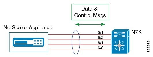
In a direct mode deployment, the service appliance, such as Citrix Netscaler Application Delivery Controller (ADC) appliance, is attached to a single Nexus Series switch. The switch can be standalone device or a VPC peer (recommended deployment). The following figure shows the topology for a direct mode deployment for a standalone Cisco Nexus switch.

Figure 1. Direct Connect Mode for the Appliance and a Standalone Switch


Note


This task describes how to configure a standalone Cisco Nexus switch in a direct mode deployment. After configuring the Cisco Remote Integrated Services Engine (RISE) on the Cisco Nexus Series switch, the appliance that is directly connected to the standalone switch is automatically configured for RISE mode and all of its ports are in operation mode. No configuration is required on the appliance in a direct mode deployment.


To configure a switch that is a vPC peer in a direct mode deployment, see the “Configuring RISE in a vPC Mode Deployment” section.

Before you begin

  • To enable auto-discovery of the appliance by the switches, use the no shutdown command to ensure that the physical ports are up by default.

  • Interconnect the ports on the appliance with the standalone or port channel of the switch.

  • Ensure that all of the switch ports to which the appliance is connected are dedicated to the appliance.

  • Make sure that you are in the correct VDC on the Cisco Nexus switch. To switch VDCs, use the switchto vdc command.

Procedure

  Command or Action Purpose

Step 1

switch# configure terminal

Enters global configuration mode.

Step 2

switch(config)# feature rise

Enables the RISE feature on the Cisco Nexus Series switch.

Step 3

switch(config)# service vlan-group group-number vlan-range

Creates a VLAN group for the NetScaler appliance data VLANs on the Cisco Nexus Series switch.

The range for the VLAN group is from 1 to 32, and the range for the configured VLANs is from 1 to 3967. You can enter the vlan-range using a comma (,), a dash (-), and the numbers.

Step 4

switch(config)# service type rise name service-name mode direct

Creates a RISE service instance, enters the RISE configuration mode on the Cisco Nexus Series switch, and specifies that the appliance is directly connected to the switch in order to establish RISE connectivity.

You can enter up to 31 alphanumeric characters for the name of the RISE service instance.

Step 5

switch(config-rise)# vlan vlan-id

Assigns a VLAN to the Netscaler Application Delivery Controller (ADC) appliance that is directly connected to the Cisco Nexus Series switch.
  • The range is from 1 to 4094.

  • This VLAN controls message communication with the supervisor over the RISE port channel. The same VLAN can be used for the Netscaler Application Delivery Controller (ADC) appliance management VLAN.

  • The VLAN ID and SVI interface must be created before the RISE channel can be established. The IP address of the SVI interface is the supervisor IP address for Cisco Netscaler Application Delivery Controller (ADC) appliance to communicate with and send the control messages.

Step 6

switch(config-rise)# ip ip-address netmask

Specifies the IP address of the Citrix Netscaler Application Delivery Controller (ADC) appliance that is directly connected to the Cisco Nexus Series switch.

This IP address controls message communication with the supervisor over the RISE port channel. The same IP address can be used for the management IP address of NetScaler appliance.

Step 7

switch(config-rise)# vlan group vlan-group

Specifies the RISE VLAN group to be used by Citrix Netscaler Application Delivery Controller (ADC) appliance.

The range is from 1 to 32.

Note

 
The trunk-allowed VLANs on the port channel must include all of the VLANs in the VLAN group as well as the VLAN for the RISE control message.

Step 8

Use one of the following:

  • switch(config-rise)# ethernet slot/port
  • switch(config-rise)# port-channel channel-number
Creates an interface for sending out RISE discovery packets.
  • The range for the slot argument is from 1 to 253. The range for the port argument is from 1 to 128.

  • The range for the channel-number argument is from 1 to 4096.

Step 9

switch(config-rise)# no shutdown

Launches the auto-discovery and bootstrap configuration process. The NetScaler ADC appliance port channel is created with the RISE IP address set at the Citrix Netscaler Application Delivery Controller (ADC) appliance.

Note

 
The Cisco Nexus Series switches associates the Netscaler Application Delivery Controller (ADC) appliance serial number with the virtual slot number for this Cisco Netscaler Application Delivery Controller (ADC) appliance.

Note

 
Discovery does not start if any required information (such as the port, RISE VLAN, RISE IP address, or switch virtual interface [SVI] of the RISE VLAN) is not provided. If the discovery times out, the virtual module is shown in the inactive state. The show rise detail command on the switch displays the reason for discovery failure.

Step 10

(Optional) switch(config-rise)# show module service

(Optional)
Displays the status of the RISE service module on the Cisco Nexus Series switch. If the RISE service module is operational, the status that is displayed is “active.”

Step 11

(Optional) switch(config-rise)# attach rise {slot slot-number | name name}

(Optional)
Connects the Cisco Nexus Series switch to the RISE service module and generates a RISE session from the switch, which allows Telnet access.
  • The slot number range varies based on the valid slot numbers for a particular VDC. The Cisco Nexus Series switch supports 32 RISE instances per VDC. The slot number range is as follows:
    • From 300 to 331 for VDC 1

    • From 332 to 363 for VDC 2

    • From 364 to 395 for VDC 3

    • From 396 to 427 for VDC 4

  • You can enter up to 32 alphanumeric characters for the RISE service module name.

  • After you enter the password, you can access the Citrix Netscaler Application Delivery Controller (ADC) appliance to configure it.

Step 12

switch(config-rise)# show rise

Displays the RISE configuration status on the Cisco Nexus Series switch. If RISE is configured on the switch, the state that is displayed is “active.”

What to do next


Note


After configuring RISE on the Cisco Nexus Series switch, the Citrix Netscaler Application Delivery Controller (ADC) appliance that is directly connected to the switch is automatically configured for RISE mode and all of its ports are in operation mode. No further configuration is required to deploy RISE on the Citrix Netscaler Application Delivery Controller (ADC) appliance.

Configuring RISE in an Indirect Mode Deployment

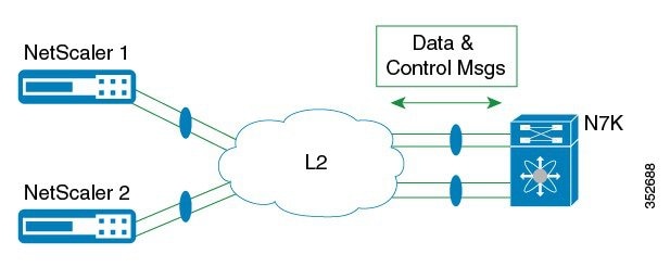
In an indirect mode deployment, a virtual service appliance, such as Citrix NetScaler Application Delivery Controller (ADC) appliance, is connected to a Cisco Nexus Series switch through a switched Layer 2 network. The topology in the following figure is for an indirect mode deployment.

Figure 2. Indirect Connect Mode Through a Layer 2 Network


This section includes the following topics:

Configuring RISE on the Cisco Nexus Switch

Before you begin

  • Enable and configure the Cisco Nexus switches as vPC peers. See the Cisco Nexus Series NX-OS Interfaces Configuration Guide for information. The following parameters must be the same on both Cisco Nexus switches:

    • The vPC ID

    • The name of the RISE service instance

    • The vPC number of the port channel

    • The IP address of the Netscaler appliance

    • The number and range of the VLAN group for the Citrix NetScaler Application Delivery Controller (ADC) appliance.

  • Make sure that you are in the correct VDC on the Cisco Nexus switch. To switch VDCs, use the switchto vdc command.

Procedure

  Command or Action Purpose

Step 1

switch# configure terminal

Enters global configuration mode.

Step 2

switch(config)# feature rise

Enables the RISE feature on the Cisco Nexus Series switch.

Step 3

switch(config)# service vlan-group group-number vlan-range

Creates a VLAN group for the Citrix NetScaler Application Delivery Controller (ADC) appliance data VLANs on the Cisco Nexus Series switch.

The range for the VLAN group is from 1 to 32, and the range for the configured VLANs is from 1 to 3967. You can enter the vlan-range using a comma (,), a dash (-), and the numbers.

Step 4

switch(config)# service type rise name service-name mode indirect

Creates a RISE service instance, enters the RISE configuration mode on the Cisco Nexus Series switch, and specifies that the appliance is indirectly connected to the switch in order to establish RISE connectivity.

You can enter up to 31 alphanumeric characters for the name of the RISE service instance.

Step 5

switch(config-rise)# vlan vlan-id

Assigns a VLAN to the Citrix NetScaler Application Delivery Controller (ADC) appliance that is directly connected to the Cisco Nexus Series switch.
  • The range is from 1 to 4094.

  • This VLAN controls message communication with the supervisor over the RISE port channel. The same VLAN can be used for the Citrix NetScaler Application Delivery Controller (ADC) appliance management VLAN.

  • The VLAN ID and SVI interface must be created before the RISE channel can be established. The IP address of the SVI interface is the supervisor IP address for Citrix NetScaler Application Delivery Controller (ADC) appliance to communicate with and send the control messages.

Step 6

switch(config-rise)# ip ip-address netmask

Specifies the IP address of the Citrix NetScaler Application Delivery Controller (ADC) appliance that is directly connected to the Cisco Nexus Series switch.

This IP address controls message communication with the supervisor over the RISE port channel. The same IP address can be used for the management IP address of NetScaler appliance.

Step 7

switch(config-rise)# vlan group vlan-group

Specifies the RISE VLAN group to be used by Citrix NetScaler Application Delivery Controller (ADC) appliance.

The range is from 1 to 32.

Note

 
The trunk-allowed VLANs on the port channel must include all of the VLANs in the VLAN group as well as the VLAN for the RISE control VLAN message.

Step 8

switch(config-rise)# no shutdown

Launches the auto-discovery and bootstrap configuration process. The Citrix NetScaler Application Delivery Controller (ADC) appliance port channel is created with the RISE IP address set at the Citrix NetScaler Application Delivery Controller (ADC) appliance.

Note

 
The Cisco Nexus Series switches associates the NetScaler appliance serial number with the virtual slot number for this Citrix NetScaler Application Delivery Controller (ADC) appliance.

Note

 
Discovery does not start if any required information (such as the port, RISE VLAN, RISE IP address, or switch virtual interface [SVI] of the RISE VLAN) is not provided. If the discovery times out, the virtual module is shown in the inactive state. The show rise command on the switch displays the reason for discovery failure.

Step 9

(Optional) switch(config-rise)# show module service

(Optional)
Displays the status of the RISE service module on the Cisco Nexus Series switch. If the RISE service module is operational, the status that is displayed is “active.”

Step 10

(Optional) switch(config-rise)# attach rise {slot slot-number | name name}

(Optional)
Connects the Cisco Nexus Series switch to the RISE service module and generates a RISE session from the switch, which allows Telnet access.
  • The slot number range varies based on the valid slot numbers for a particular VDC. The Cisco Nexus Series switch supports 32 RISE instances per VDC. The slot number range is as follows:
    • From 300 to 331 for VDC 1

    • From 332 to 363 for VDC 2

    • From 364 to 395 for VDC 3

    • From 396 to 427 for VDC 4

  • You can enter up to 32 alphanumeric characters for the RISE service module name.

  • After you enter the password, you can access the Citrix NetScaler Application Delivery Controller (ADC) appliance to configure it.

Step 11

switch(config-rise)# show rise

Displays the RISE configuration status on the Cisco Nexus Series switch. If RISE is configured on the switch, the state that is displayed is “active.”

Configuring NSIP on the Appliance

The NetScaler management IP address (NSIP) is the IP address for management and general system access to the Citrix NetScaler Application Delivery Controller (ADC) appliance and for high availability (HA) communication.

Configuring NSIP Using the CLI

You can configure the NSIP on your appliance by using either the configuration prompts or the command-line interface (CLI).


Note


To prevent an attacker from impeding your ability to send packets to the appliance, choose a nonroutable IP address on your organization's LAN as your appliance IP address.
Before you begin

Ensure that a port channel is configured on the appliance and that the appliance's physical ports are mapped to this port channel.

Procedure

Perform one of the following tasks:

Option Description

config ns

Displays prompts for configuring the NSIP.

set ns config -ipaddress address -netmask netmask

add ns ip ip-address netmask -type type

add route network netmask gateway

save ns config

reboot

Configures the NSIP using the CLI.

Example:

The following example shows how to configure the NSIP using the CLI:

set ns config -ipaddress 10.102.29.60 -netmask 255.255.255.0
save ns

Configuring NSIP Using the Configuration Utility

Before you begin
  • Create a port channel on the Citrix NetScaler Application Delivery Controller (ADC) appliance and map its physical ports to this port channel.

Procedure

Step 1

Navigate to System > Settings.

Step 2

In the details pane, under Settings, click Change NSIP Settings.

Step 3

In the Configure NSIP Settings dialog box, set the parameters. For a description of a parameter, hover the mouse cursor over the corresponding field.

Step 4

Under Interfaces, choose the interfaces from the Available Interfaces list and click Add to move them to the Configured Interfaces list.

Step 5

Click OK. In the Warning dialog box, click OK. The configuration takes effect after the Citrix NetScaler Application Delivery Controller (ADC) appliance is restarted.


Configuring a NSVLAN on Citrix NetScaler Application Delivery Controller (ADC) Appliance

The NSVLAN is a VLAN to which the NetScaler management IP (NSIP) address's subnet is bound. The NSIP subnet is available only on interfaces that are associated with NSVLAN. By default, NSVLAN is VLAN1, but you can designate a different VLAN as NSVLAN. If you designate a different VLAN as an NSVLAN, you must reboot the Citrix NetScaler Application Delivery Controller (ADC) appliance for the change to take effect. After the reboot, NSIP subnet traffic is restricted to the new NSVLAN.

Perform only one of the following tasks:

Configuring NSVLAN Using the CLI

Enter the following commands prompt to configure NSVLAN using the CLI:

Before you begin
  • Create a port channel on the Citrix NetScaler Application Delivery Controller (ADC) appliance and map its physical ports to this port channel.

  • Configure the NS IP address (NSIP) on the appliance.

Procedure

Step 1

set ns config - nsvlan positive_integer - ifnum interface_name ... [-tagged (YES | NO)]

Note

 
You must reboot the appliance for the configuration to take effect.
set ns config -nsvlan 300 -ifnum 1/1 1/2 1/3 -tagged NO
save config

Step 2

(Optional) show ns config

set ns config -nsvlan 300 -ifnum 1/1 1/2 1/3 -tagged NO
save config

Step 3

(Optional) unset ns config -nsvlan

Restores the default configuration.


Configuring NSVLAN Using the Configuration Utility

Before you begin
  • Create a port channel on the Citrix NetScaler Application Delivery Controller (ADC) appliance and map its physical ports to this port channel.

  • Configure the NetScaler IP address (NSIP) on the appliance.

Procedure

Step 1

Navigate to System > Settings.

Step 2

In the details pane, under Settings, click Change NSVLAN Settings.

Step 3

In the Configure NSVLAN Settings dialog box, set the parameters. For a description of a parameter, hover the mouse cursor over the corresponding field.

Step 4

Under Interfaces, choose the interfaces from the Available Interfaces list and click Add to move them to the Configured Interfaces list.

Step 5

Click OK. In the Warning dialog box, click OK. The configuration takes effect after the Citrix NetScaler Application Delivery Controller (ADC) appliance is restarted.


Configuring RISE in vPC Mode (Recommended Deployment Mode)

In a virtual port channel (vPC) deployment, two service appliances, such a Citrix NetScaler Application Delivery Controller (ADC) appliance, are each connected to separate Cisco Nexus Series switches that are in vPC mode through a peer link. This is the recommended topology for deploying the RISE feature on a Cisco Nexus switch and a Citrix NetScaler Application Delivery Controller (ADC) appliance.

This section includes the following topics:

Configuring RISE in a vPC Direct Mode Deployment

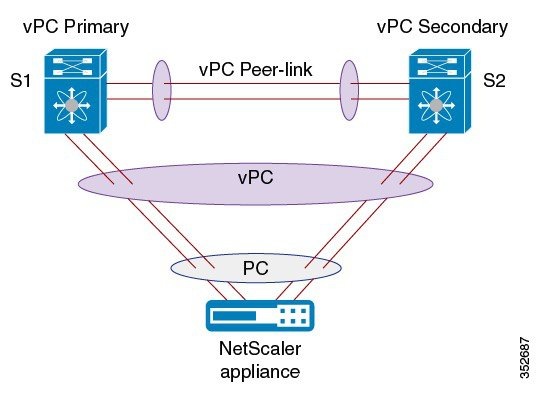
In an direct mode deployment, the service appliance, such as appliance, is attached to a single Nexus Series switch. The switch can be standalone device or a VPC peer (recommended deployment). The following figure shows the topologies for a vPC direct mode deployment.
Figure 3. vPC Direct Connect Mode for Connecting to vPC Peer Switches


Note


This task describes how to configure a vPC peer switch in a direct mode deployment. After configuring RISE on the Cisco Nexus Series switch, the Citrix NetScaler Application Delivery Controller (ADC) appliance that is directly connected to the switch is automatically configured for RISE mode and all of its ports are in operation mode. No configuration is required on the Citrix NetScaler appliance in a direct mode deployment.


Repeat these steps to configure each vPC peer switch to which an appliance is connected.

Before you begin

  • Enable and configure the Cisco Nexus switches as vPC peers. See the Cisco Nexus Series NX-OS Interfaces Configuration Guide for information. The following parameters must be the same on both Cisco Nexus switches:

    • The vPC ID

    • The name of the RISE service instance

    • The vPC number of the port channel

    • The IP address of the appliance

    • The number and range of the VLAN group for the ADC appliance

  • Make sure that you are in the correct VDC on the Cisco Nexus switch. To switch VDCs, use the switchto vdc command.

Procedure

  Command or Action Purpose

Step 1

switch# configure terminal

Enters global configuration mode.

Step 2

switch(config)# feature rise

Enables the RISE feature on the Cisco Nexus Series switch.

Step 3

switch(config)# service vlan-group group-number vlan-range

Creates a VLAN group for the NetScaler appliance data VLANs on the Cisco Nexus Series switch.

The range for the VLAN group is from 1 to 32, and the range for the configured VLANs is from 1 to 3967. You can enter the vlan-range using a comma (,), a dash (-), and the numbers.

Step 4

switch(config)# service type rise name service-name mode vpc

Creates a RISE service instance, enters the RISE configuration mode on the Cisco Nexus Series switch, and specifies that the appliance is directly connected to the switch in order to establish RISE connectivity.

You can enter up to 31 alphanumeric characters for the name of the RISE service instance.

Step 5

switch(config-rise)# vlan vlan-id

Assigns a VLAN to the NetScaler appliance that is directly connected to the Cisco Nexus Series switch.
  • The range is from 1 to 4094.

  • This VLAN controls message communication with the supervisor over the RISE port channel. The same VLAN can be used for the Citrix Netscaler Application Delivery Controller (ADC) appliance management VLAN.

  • The VLAN ID and SVI interface must be created before the RISE channel can be established. The IP address of the SVI interface is the supervisor IP address for Citrix NetScaler Application Delivery Controller (ADC) appliance to communicate with and send the control messages.

Step 6

switch(config-rise)# ip ip-address netmask

Specifies the IP address of the Citrix NetScaler Application Delivery Controller (ADC) appliance that is directly connected to the Cisco Nexus 7000 Series switch.

This IP address controls message communication with the supervisor over the RISE port channel. The same IP address can be used for the management IP address of Citrix Netscaler Application Delivery Controller (ADC) appliance.

Step 7

switch(config-rise)# vlan group vlan-group

Specifies the RISE VLAN group to be used by Citrix NetScaler Application Delivery Controller (ADC) appliance.

The range is from 1 to 32.

Note

 
The trunk-allowed VLANs on the port channel must include all of the VLANs in the VLAN group as well as the VLAN for the RISE control message.

Step 8

Use one of the following:

  • switch(config-rise)# ethernet slot/port
  • switch(config-rise)# port-channel channel-number
Creates an interface for sending out RISE discovery packets.
  • The range for the slot argument is from 1 to 253. The range for the port argument is from 1 to 128.

  • The range for the channel-number argument is from 1 to 4096.

Step 9

switch(config-rise)# no shutdown

Launches the auto-discovery and bootstrap configuration process. The Citrix NetScaler Application Delivery Controller (ADC) appliance port channel is created with the RISE IP address set at the Citrix NetScaler Application Delivery Controller (ADC) appliance.

Note

 
The Cisco Nexus Series switches associates the NetScaler appliance serial number with the virtual slot number for this Citrix Netscaler Application Delivery Controller (ADC) appliance.

Note

 
Discovery does not start if any required information (such as the port, RISE VLAN, RISE IP address, or switch virtual interface [SVI] of the RISE VLAN) is not provided. If the discovery times out, the virtual module is shown in the inactive state. The show rise command on the switch displays the reason for discovery failure.

Step 10

(Optional) switch(config-rise)# show module service

(Optional)
Displays the status of the RISE service module on the Cisco Nexus Series switch. If the RISE service module is operational, the status that is displayed is “active.”

Step 11

(Optional) switch(config-rise)# attach rise {slot slot-number | name name}

(Optional)
Connects the Cisco Nexus Series switch to the RISE service module and generates a RISE session from the switch, which allows Telnet access.
  • The slot number range varies based on the valid slot numbers for a particular VDC. The Cisco Nexus Series switch supports 32 RISE instances per VDC. The slot number range is as follows:
    • From 300 to 331 for VDC 1

    • From 332 to 363 for VDC 2

    • From 364 to 395 for VDC 3

    • From 396 to 427 for VDC 4

  • You can enter up to 32 alphanumeric characters for the RISE service module name.

  • After you enter the password, you can access the Citrix NetScaler Application Delivery Controller (ADC) appliance to configure it.

Step 12

switch(config-rise)# show rise

Displays the RISE configuration status on the Cisco Nexus Series switch. If RISE is configured on the switch, the state that is displayed is “active.”

Configuring RISE in a vPC Indirect Mode Deployment

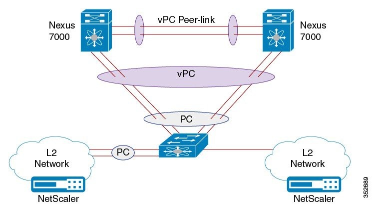
In a vPC indirect mode deployment, the service appliance, such as Citrix NetScaler Citrix Netscaler Application Delivery Controller (ADC) appliance, is indirectly attached to a Cisco Nexus vPC peer through a Layer 2 network. The following figure shows the topology for a vPC indirect mode deployment.
Figure 4. vPC Indirect Connect Mode for Connecting to vPC Perr Switches


This section includes the following topics:

Configuring RISE on the Cisco Nexus Switch

Before you begin
  • Enable and configure the Cisco Nexus switches as vPC peers. See the Cisco Nexus Series NX-OS Interfaces Configuration Guide for information. The following parameters must be the same on both Cisco Nexus switches:

    • The vPC ID

    • The name of the RISE service instance

    • The vPC number of the port channel

    • The IP address of the Netscaler appliance

    • The number and range of the VLAN group for the Citrix NetScaler Application Delivery Controller (ADC) appliance.

  • Make sure that you are in the correct VDC on the Cisco Nexus switch. To switch VDCs, use the switchto vdc command.

Procedure
  Command or Action Purpose

Step 1

switch# configure terminal

Enters global configuration mode.

Step 2

switch(config)# feature rise

Enables the RISE feature on the Cisco Nexus Series switch.

Step 3

switch(config)# service vlan-group group-number vlan-range

Creates a VLAN group for the Citrix NetScaler Application Delivery Controller (ADC) appliance data VLANs on the Cisco Nexus Series switch.

The range for the VLAN group is from 1 to 32, and the range for the configured VLANs is from 1 to 3967. You can enter the vlan-range using a comma (,), a dash (-), and the numbers.

Step 4

switch(config)# service type rise name service-name mode indirect

Creates a RISE service instance, enters the RISE configuration mode on the Cisco Nexus Series switch, and specifies that the appliance is indirectly connected to the switch in order to establish RISE connectivity.

You can enter up to 31 alphanumeric characters for the name of the RISE service instance.

Step 5

switch(config-rise)# vlan vlan-id

Assigns a VLAN to the Citrix NetScaler Application Delivery Controller (ADC) appliance that is directly connected to the Cisco Nexus Series switch.
  • The range is from 1 to 4094.

  • This VLAN controls message communication with the supervisor over the RISE port channel. The same VLAN can be used for the Citrix NetScaler Application Delivery Controller (ADC) appliance management VLAN.

  • The VLAN ID and SVI interface must be created before the RISE channel can be established. The IP address of the SVI interface is the supervisor IP address for Citrix NetScaler Application Delivery Controller (ADC) appliance to communicate with and send the control messages.

Step 6

switch(config-rise)# ip ip-address netmask

Specifies the IP address of the Citrix NetScaler Application Delivery Controller (ADC) appliance that is directly connected to the Cisco Nexus Series switch.

This IP address controls message communication with the supervisor over the RISE port channel. The same IP address can be used for the management IP address of NetScaler appliance.

Step 7

switch(config-rise)# vlan group vlan-group

Specifies the RISE VLAN group to be used by Citrix NetScaler Application Delivery Controller (ADC) appliance.

The range is from 1 to 32.

Note

 
The trunk-allowed VLANs on the port channel must include all of the VLANs in the VLAN group as well as the VLAN for the RISE control VLAN message.

Step 8

switch(config-rise)# no shutdown

Launches the auto-discovery and bootstrap configuration process. The Citrix NetScaler Application Delivery Controller (ADC) appliance port channel is created with the RISE IP address set at the Citrix NetScaler Application Delivery Controller (ADC) appliance.

Note

 
The Cisco Nexus Series switches associates the NetScaler appliance serial number with the virtual slot number for this Citrix NetScaler Application Delivery Controller (ADC) appliance.

Note

 
Discovery does not start if any required information (such as the port, RISE VLAN, RISE IP address, or switch virtual interface [SVI] of the RISE VLAN) is not provided. If the discovery times out, the virtual module is shown in the inactive state. The show rise command on the switch displays the reason for discovery failure.

Step 9

(Optional) switch(config-rise)# show module service

(Optional)
Displays the status of the RISE service module on the Cisco Nexus Series switch. If the RISE service module is operational, the status that is displayed is “active.”

Step 10

(Optional) switch(config-rise)# attach rise {slot slot-number | name name}

(Optional)
Connects the Cisco Nexus Series switch to the RISE service module and generates a RISE session from the switch, which allows Telnet access.
  • The slot number range varies based on the valid slot numbers for a particular VDC. The Cisco Nexus Series switch supports 32 RISE instances per VDC. The slot number range is as follows:
    • From 300 to 331 for VDC 1

    • From 332 to 363 for VDC 2

    • From 364 to 395 for VDC 3

    • From 396 to 427 for VDC 4

  • You can enter up to 32 alphanumeric characters for the RISE service module name.

  • After you enter the password, you can access the Citrix NetScaler Application Delivery Controller (ADC) appliance to configure it.

Step 11

switch(config-rise)# show rise

Displays the RISE configuration status on the Cisco Nexus Series switch. If RISE is configured on the switch, the state that is displayed is “active.”

Configuring NSIP on the Appliance

The NetScaler management IP address (NSIP) is the IP address for management and general system access to the Citrix NetScaler Application Delivery Controller (ADC) appliance and for high availability (HA) communication.

Configuring NSIP Using the CLI

You can configure the NSIP on your appliance by using either the configuration prompts or the command-line interface (CLI).


Note


To prevent an attacker from impeding your ability to send packets to the appliance, choose a nonroutable IP address on your organization's LAN as your appliance IP address.
Before you begin

Ensure that a port channel is configured on the appliance and that the appliance's physical ports are mapped to this port channel.

Procedure

Perform one of the following tasks:

Option Description

config ns

Displays prompts for configuring the NSIP.

set ns config -ipaddress address -netmask netmask

add ns ip ip-address netmask -type type

add route network netmask gateway

save ns config

reboot

Configures the NSIP using the CLI.

Example:

The following example shows how to configure the NSIP using the CLI:

set ns config -ipaddress 10.102.29.60 -netmask 255.255.255.0
save ns

Configuring NSIP Using the Configuration Utility
Before you begin
  • Create a port channel on the Citrix NetScaler Application Delivery Controller (ADC) appliance and map its physical ports to this port channel.

Procedure

Step 1

Navigate to System > Settings.

Step 2

In the details pane, under Settings, click Change NSIP Settings.

Step 3

In the Configure NSIP Settings dialog box, set the parameters. For a description of a parameter, hover the mouse cursor over the corresponding field.

Step 4

Under Interfaces, choose the interfaces from the Available Interfaces list and click Add to move them to the Configured Interfaces list.

Step 5

Click OK. In the Warning dialog box, click OK. The configuration takes effect after the Citrix NetScaler Application Delivery Controller (ADC) appliance is restarted.


Configuring a NSVLAN on Citrix NetScaler Application Delivery Controller (ADC) Appliance

The NSVLAN is a VLAN to which the NetScaler management IP (NSIP) address's subnet is bound. The NSIP subnet is available only on interfaces that are associated with NSVLAN. By default, NSVLAN is VLAN1, but you can designate a different VLAN as NSVLAN. If you designate a different VLAN as an NSVLAN, you must reboot the Citrix NetScaler Application Delivery Controller (ADC) appliance for the change to take effect. After the reboot, NSIP subnet traffic is restricted to the new NSVLAN.

Perform only one of the following tasks:

Configuring NSVLAN Using the CLI

Enter the following commands prompt to configure NSVLAN using the CLI:

Before you begin
  • Create a port channel on the Citrix NetScaler Application Delivery Controller (ADC) appliance and map its physical ports to this port channel.

  • Configure the NS IP address (NSIP) on the appliance.

Procedure

Step 1

set ns config - nsvlan positive_integer - ifnum interface_name ... [-tagged (YES | NO)]

Note

 
You must reboot the appliance for the configuration to take effect.
set ns config -nsvlan 300 -ifnum 1/1 1/2 1/3 -tagged NO
save config

Step 2

(Optional) show ns config

set ns config -nsvlan 300 -ifnum 1/1 1/2 1/3 -tagged NO
save config

Step 3

(Optional) unset ns config -nsvlan

Restores the default configuration.


Configuring NSVLAN Using the Configuration Utility
Before you begin
  • Create a port channel on the Citrix NetScaler Application Delivery Controller (ADC) appliance and map its physical ports to this port channel.

  • Configure the NetScaler IP address (NSIP) on the appliance.

Procedure

Step 1

Navigate to System > Settings.

Step 2

In the details pane, under Settings, click Change NSVLAN Settings.

Step 3

In the Configure NSVLAN Settings dialog box, set the parameters. For a description of a parameter, hover the mouse cursor over the corresponding field.

Step 4

Under Interfaces, choose the interfaces from the Available Interfaces list and click Add to move them to the Configured Interfaces list.

Step 5

Click OK. In the Warning dialog box, click OK. The configuration takes effect after the Citrix NetScaler Application Delivery Controller (ADC) appliance is restarted.


Route Health Injection

Route Health Injection (RHI)) allows NetScaler to advertise the VIPs to upstream and downstream routers. The NetScaler uses health probes together. When a VIP becomes unavailable, NetScaler withdraws the RHI information.

Once the Service Card (SC) Engine on the Cisco Nexus 7000 Series switch receives the RHI advertised messages from the Intelligent Service Card Client (ISCC) residing on the NetScaler appliance, the switch updates its routing tables to reflect the new route in the RHI message.

Use the show routing command on the switch to display the route automatically inserted for the VIP.

Service Card Engine

The Service Card (SC) Engine handles tasks related to the initialization and flow of Remote Health Injection (RHI) messages.

During the SC Engine initialization, the SC Engine registers with the Universal Routing information Base (URIB) as a URIB client so that it can access the routing database. After registration is successful, the SC Engine can add routes received from NetScaler to the routing database.

When the ISCC receives an RHI message from NetScaler, it sends a TLV and encrypted message to SC Engine containing the RHI payload and RISE headers. SC Engine transport decrypts and processes the RHI message. Each RHI message contains a common header with RHI opcode and a RHI request payload. The message header also contains the number of RHI entries contained in the RHI request payload.

The SC Engine also checks the status of the SVI for the VLAN sent by NetScaler. It obtains the interface number for the SVI and call the URIB APIs to add, delete, or delete all routes. The other parameters sent in the URIB API are present in the RHI request payload received by the SC Engine. All routes are added as static routes to the VRF that this SVI is associated with.

Intelligent Service Card Client

The Intelligent Service Card Client (ISCC) is the SDK component on NetScaler The Route Health Injection (RHI) message is a pass-through message for the ISCC. The ISCC copies the payload from NetScaler into the RHI message payload directed towards the Service Card (SC) Engine.

The SC Engine sends an acknowledgment when its processes the RHI message, then the ISCC transparently sends the acknowledgment to NetScaler. NetScaler is responsible for starting a timer and handling the failure if it does not receive an acknowledgment in time.

Universal Routing Information Base

The Universal Routing Information Base (URIB) hosts APIs to add, delete and modify routes on the Supervisor. The details of route modification are transparent to the SC Engine.

Verifying the RISE Configuration

To display the RISE configuration on the Cisco Nexus Series switch, perform one of the following tasks.


Note


For detailed information about the fields in the output from these commands, see the “Cisco NX-OS RISE Commands” chapter.
Command Purpose

show module service

Displays the status of the RISE service module on the Cisco Nexus Series switch.

show rise [detail]

Displays the RISE configuration status on the Cisco Nexus Series switch.

show rise vlan-group

Displays VLAN group information for the NetScaler appliance data VLANs on the Cisco Nexus Series switch.

show running-config services

Displays the RISE running configuration on the Cisco Nexus Series switch.

show tech-support services [detail]

Displays troubleshooting information for RISE on the Cisco Nexus Series switch.

The following example is partial sample output from the show rise command:
switch# show rise
Name          Slot Vdc Rise-Ip         State        Interface
                Id  Id
------------- ---- --- --------------- ------------ ---------
mpx205a       332   2   10.90.14.216    active       Po2051

The following example is partial sample output from the show rise detail command:
swicth# show rise detail

RISE module name: mpx205a
  State: active
  Admin state: Enabled
  Interface: Po2051
  RISE Channel connectivity via interface Po2051
  Mode: vpc
  Slot id: 332
  Service token: 0x2
  Serial number: MH8C02AM50
  SUP IP: 10.90.14.138
  RISE IP: 10.90.14.216
  VDC id: 2
  VLAN: 99
  VLAN group: 20
  VLAN list: 99-101
  Data Interface: N/A
To display the RISE configuration on the Citrix Netscaler Application Delivery Controller (ADC) appliance, perform one of the following:
Command Purpose

show rise apbrsvc

Displays the RISE configuration status on the Citrix Netscaler Application Delivery Controller (ADC) appliance.

The following example is sample output from the show rise profile command:

mpx24> show rise profile

1)      Service Name   : mpx4
        Status         : Active
        Mode           : vPC-Direct
        Device Id      : FOC1824R00P
        Slot Number    : 300
        VDC Id         : 1
        vPC Id         : 510
        SUP IP         : 172.16.0.2
        VLAN           : 301
        VLAN Group     : 1
        ISSU           : None
        Interface      : LA/1 : 10/3 10/4
2)      Service Name   : mpx4
        Status         : Active
        Mode           : vPC-Direct
        Device Id      : FOC1751R0QV
        Slot Number    : 300
        VDC Id         : 1
        vPC Id         : 510
        SUP IP         : 172.16.0.3
        VLAN           : 301
        VLAN Group     : 1
        ISSU           : None
        Interface      : LA/1 : 10/7 10/8


 Done

Verifying the SC Engine Configuration

To display the SC Engine configuration on the Cisco Nexus Series switch, perform one of the following tasks.


Note


For detailed information about the fields in the output from these commands, see the “Cisco NX-OS RISE Commands” chapter.
Command Purpose

show system internal SC_Engine rise version

Displays the version of each service and version of SC_Engine on the Cisco Nexus Series switch.

show system internal SC_Engine pkt-stats

Displays all the statistics of the SC_Engine packet at RX/TX on a rise socket on the Cisco Nexus Series switch.

show system internal SC_Engine mem-stats

Displays VLAN group information for the NetScaler appliance data VLANs on the Cisco Nexus Series switch.

show system internal SC_Engine event-history debugs[detail]

Displays the RISE running configuration on the Cisco Nexus Series switch.

show system internal SC_Engine event-history-errors

Displays troubleshooting information for RISE on the Cisco Nexus Series switch.

show system internal SC_Engine event-history-all

Displays profile information for RISE on the Cisco Nexus Series switch.

show system internal SC_Engine event-history warnings

Displays profile information for RISE on the Cisco Nexus Series switch.

The following example is partial sample output from the show system internal SC_Engine rise version command:
switch#  show system internal SC_Engine rise version
Name       Version
-------  ---------
SC_Engine  2.1
MPX        2.1
Emu        2.1
VPX        2.1

The following example is partial sample output from the show system internal SC_Engine pkt-stats command:
switch# show system internal SC_Engine packet-stats
Service name: MPX
--------------------------------  --------  --------
Opcode                            Tx        Rx
--------------------------------  --------  --------
RISE_OPC_SVC_RHI                  0         0
RISE_OPC_SVC_RHI_BULK             0         0
RISE_OPC_SVC_APBR                 0         0
RISE_OPC_SVC_APBR_BULK            0         0
RISE_OPC_SVC_DISCOVERY            57869     57869
RISE_OPC_SVC_BOOTSTRAP_CONFIRM    57869     0
RISE_OPC_SVC_PORT_STATUS          0         0
RISE_OPC_SVC_ISSU                 0         0
RISE_OPC_SVC_VLAN_GROUP           0         0
RISE_OPC_SVC_SYS_INFO             0         0
RISE_OPC_SVC_DELETE               0         0
RISE_OPC_SVC_BULK                 0         0
RISE_OPC_CP_SLOT_DOWN             0         0
RISE_OPC_SUP_IP_CONFIG            0         0
RISE_OPC_RISE_IP_CONFIG           0         0
RISE_OPC_SVC_DIRECT_DISCOVERY     2         2
RISE_OPC_SVC_DIRECT_BOOTSTRAP_CO  2         2
RISE_OPC_SVC_DIRECT_BOOTSTRAP_4_  0         0
RISE_OPC_SVC_DIRECT_PORTS_START   2         2
RISE_OPC_SVC_DIRECT_PORTS_END     2         2
RISE_OPC_SVC_PURGE                0         0
RISE_OPC_SVC_PBR_ENABLE           0         0
RISE_OPC_SVC_PBR_DISABLE          0         0
--------------------------------  -------- --------
                          Total:  115746    57877

Service name: Emu
--------------------------------  --------  --------
Opcode                            Tx        Rx
--------------------------------  --------  --------
RISE_OPC_SVC_RHI                  0         0
RISE_OPC_SVC_RHI_BULK             0         0
RISE_OPC_SVC_APBR                 0         0
RISE_OPC_SVC_APBR_BULK            3         3
RISE_OPC_SVC_DISCOVERY            58895     58895
RISE_OPC_SVC_BOOTSTRAP_CONFIRM    58895     0
RISE_OPC_SVC_PORT_STATUS          0         0
RISE_OPC_SVC_ISSU                 0         0
RISE_OPC_SVC_VLAN_GROUP           0         0
RISE_OPC_SVC_SYS_INFO             0         0
RISE_OPC_SVC_DELETE               0         0
RISE_OPC_SVC_BULK                 0         0
RISE_OPC_CP_SLOT_DOWN             0         0
RISE_OPC_SUP_IP_CONFIG            0         0
RISE_OPC_RISE_IP_CONFIG           0         0
RISE_OPC_SVC_DIRECT_DISCOVERY     0         0
RISE_OPC_SVC_DIRECT_BOOTSTRAP_CO  0         0
RISE_OPC_SVC_DIRECT_BOOTSTRAP_4_  0         0
RISE_OPC_SVC_DIRECT_PORTS_START   0         0
RISE_OPC_SVC_DIRECT_PORTS_END     0         0
RISE_OPC_SVC_PURGE                0         0
RISE_OPC_SVC_PBR_ENABLE           0         0
RISE_OPC_SVC_PBR_DISABLE          0         0
--------------------------------  -------- --------
                          Total:  117793    58898

Service name: VPX
--------------------------------  --------  --------
Opcode                            Tx        Rx
--------------------------------  --------  --------
RISE_OPC_SVC_RHI                  0         0
RISE_OPC_SVC_RHI_BULK             0         0
RISE_OPC_SVC_APBR                 0         0
RISE_OPC_SVC_APBR_BULK            0         0
RISE_OPC_SVC_DISCOVERY            50588     50587
RISE_OPC_SVC_BOOTSTRAP_CONFIRM    50587     0
RISE_OPC_SVC_PORT_STATUS          0         0
RISE_OPC_SVC_ISSU                 0         0
RISE_OPC_SVC_VLAN_GROUP           0         0
RISE_OPC_SVC_SYS_INFO             0         0
RISE_OPC_SVC_DELETE               0         0
RISE_OPC_SVC_BULK                 0         0
RISE_OPC_CP_SLOT_DOWN             0         0
RISE_OPC_SUP_IP_CONFIG            0         0
RISE_OPC_RISE_IP_CONFIG           0         0
RISE_OPC_SVC_DIRECT_DISCOVERY     0         0
RISE_OPC_SVC_DIRECT_BOOTSTRAP_CO  0         0
RISE_OPC_SVC_DIRECT_BOOTSTRAP_4_  0         0
RISE_OPC_SVC_DIRECT_PORTS_START   0         0
RISE_OPC_SVC_DIRECT_PORTS_END     0         0
RISE_OPC_SVC_PURGE                0         0
RISE_OPC_SVC_PBR_ENABLE           0         0
RISE_OPC_SVC_PBR_DISABLE          0         0
--------------------------------  -------- --------
                          Total:  101175    50587       332   2   10.90.14.216    active       Po2051

The following example is partial sample output from the show system internal SC_Engine mem-stats command:
switch#  show system internal SC_Engine mem-stats
Private Mem stats for UUID : Malloc track Library(103) Max types: 5
--------------------------------------------------------------------------------
Curr alloc: 1353 Curr alloc bytes: 96546(94k)


Private Mem stats for UUID : Non mtrack users(0) Max types: 130
--------------------------------------------------------------------------------
Curr alloc: 364 Curr alloc bytes: 39020(38k)


Private Mem stats for UUID : libsdwrap(115) Max types: 22
--------------------------------------------------------------------------------
Curr alloc: 34 Curr alloc bytes: 1149192(1122k)

...

The following example is partial sample output from the show system internal SC_Engine event-history debugs[detail] command:
switch# show system internal SC_Engine event-history debugs
1) Event:E_DEBUG, length:45, at 451405 usecs after Fri Nov 25 00:39:14 2011
    [104] SC_Engine_demux(1198):[FU_EVENT_CAT_MTS_MSG
]


2) Event:E_DEBUG, length:49, at 451400 usecs after Fri Nov 25 00:39:14 2011
    [104] SC_Engine_demux(1190):[Got a message event cat 1]


3) Event:E_DEBUG, length:49, at 451395 usecs after Fri Nov 25 00:39:14 2011
    [104] SC_Engine_demux(1189):[Got a message event cat 1]

The following example is partial sample output from the show system internal SC_Engine event-history-errors command:
switch# show system internal SC_Engine event-history-errors
1) Event:E_DEBUG, length:45, at 771310 usecs after Fri Nov 25 00:41:01 2011
    [104] SC_Engine_demux(1198):[FU_EVENT_CAT_MTS_MSG]
2) Event:E_DEBUG, length:49, at 771305 usecs after Fri Nov 25 00:41:01 2011
    [104] SC_Engine_demux(1190):[Got a message event cat 1]
3) Event:E_DEBUG, length:49, at 771301 usecs after Fri Nov 25 00:41:01 2011
    [104] SC_Engine_demux(1189):[Got a message event cat 1]
...

The following example is partial sample output from the show system internal SC_Engine event-history-all command:
switch# show system internal SC_Engine event-history-all
1) Event:E_DEBUG, length:45, at 341769 usecs after Tue Nov 29 21:25:32 2011
    [104] SC_Engine_demux(1198):[FU_EVENT_CAT_MTS_MSG]
2) Event:E_DEBUG, length:49, at 341764 usecs after Tue Nov 29 21:25:32 2011
    [104] SC_Engine_demux(1190):[Got a message event cat 1]
3) Event:E_DEBUG, length:49, at 341759 usecs after Tue Nov 29 21:25:32 2011
    [104] SC_Engine_demux(1189):[Got a message event cat 1]

The following example is partial sample output from the show system internal SC_Engine event-history warnings command:
switch# show system internal SC_Engine event-history warnings
1) Event:E_DEBUG, length:74, at 760859 usecs after Thu Nov 24 21:19:16 2011
    [103] SC_Engine_restore_pss_data(577):[(Error) 0x40480010 in pss2_move2location]
etc…

Monitoring Cisco RISE

Use the show rise profile command on the Citrix Netscaler Application Delivery Controller (ADC) appliance to display RISE statistics, as shown in the following example:

For vPC mode (direct):

mpx24> show rise profile
1)      Service Name   : mpx24
        Status         : Active
        Mode           : vPC-Direct
        Device Id      : FOC2865R92P
        Slot Number    : 300
        VDC Id         : 1
        vPC Id         : 510
        SUP IP         : 172.16.0.2
        VLAN           : 10
        VLAN Group     : 1
        ISSU           : None
        Interface      : LA/1 : 10/3 10/4

For Indirect mode (in vPC, only 1 out of 2 entries shown):

1)	Service Name   : profile_301
	Status         : Active
	Mode           : Indirect
	Device Id      : N77-C7706:FXS1736Q96T
	Slot Number    : 332
	VDC Id         : 2
	vPC Id         : 0
	SUP IP         : 172.16.0.2
	VLAN           : 10
	VLAN Group     : 24
	ISSU           : None
	Interface      : N/A

Configuration Examples for RISE

Example: RISE Direct Mode Deployment

This example shows how to configure a RISE service on a standalone Cisco Nexus Series switch that is connected directly to a Citrix Netscaler Application Delivery Controller (ADC) appliance.


Note


When the Citrix Netscaler Application Delivery Controller (ADC) appliance is directly connected to a standalone Cisco Nexus Series switch and the RISE control channel is configured on the Cisco Nexus Series switch, the Citrix Netscaler Application Delivery Controller (ADC) appliance is automatically configured for RISE mode and all of its ports are set to operation mode.


switch# configure terminal
switch(config)# port-channel 300
switch(config-if)# switchport trunk allowed vlan 20,30,40
switch(config-if)# no shut
switch(config)# ethernet 5/1-2
switch(config-if-range)# channel-group 100
switch(config)# ethernet 6/1-2
switch(config-if-range)# channel-group 100
switch(config)# service vlan-group 1 20,30,40
switch(config)# feature rise
switch(config)# service type rise name ns21 mode direct
switch(config-rise)# vlan 3
switch(config-rise)# ip 3.3.3.21 255.0.0.0
switch(config-rise)# vlan group 1
switch(config-rise)# port-channel 100
switch(config-rise)# no shutdown

switch(config-rise)# attach rise slot 300
Attaching to RISE 300 ...

Username:nsroot
Warning: Permanently added '3.3.3.21' (RSA) to the list of known hosts.
Password: 
Last login: Fri Sep 27 14:58:44 2013 from 10.99.0.15
Copyright (c) 1980, 1983, 1986, 1988, 1990, 1991, 1993, 1994
        The Regents of the University of California.  All rights reserved.

 Done		

Example: RISE Indirect Mode Deployment

This example shows how to configure a RISE service on the Cisco Nexus Series switch that is connected to a Citrix Netscaler Application Delivery Controller (ADC) appliance through a Layer 2 network:

switch# configure terminal
switch(config)# port-channel 301
switch(config-if)# switchport
switch(config-if)# switchport mode trunk
switch(config-if)# switchport allowed vlan 10,20,30,40,50,60
switch(config)# ethernet 5/1-2
switch(config-if-range)# channel-group 100
switch(config-if-range)# no shutdown
switch(config)# ethernet 6/1-2
switch(config-if-range)# channel-group 100
switch(config-if-range)# no shutdown
switch(config)# service vlan-group 1 20,30,40
switch(config)# feature rise
switch(config)# service type rise name ns22 mode indirect
switch(config-rise)# vlan 10
switch(config-rise)# ip 3.3.3.22 255.0.0.0
switch(config-rise)# vlan group 22
switch(config-rise)# no shutdown
switch(config-rise)# show module service

switch(config-rise)# attach rise slot 301
rise_ent->rise_ip = 2010101
ipaddr 10.10.10.5
Attaching to RISE 301 ...
To exit type 'exit', to abort type '$.'
Telnet rlogin escape character is '$'.
Trying 10.10.10.5...
Connected to 10.10.10.5.
Escape character is '^]'.

The following sample output from show commands enables you to verify the configuration:

switch(config-rise)# show rise detail
RISE module name: ns22
  State: active
  Admin state: enabled
  Interface: N/A
  Mode: indirect
  Slot id: 301
  Service token: 0x1
  Serial number: HE2H81UJ47
  SUP IP: 3.101.0.10
  RISE IP: 10.10.10.5
  VDC id: 1
  VLAN: 10
  VLAN group: 22
  VLAN list: 122,221-224,231-234

Example: RISE vPC Direct Mode Deployment

You configure RISE on the Cisco Nexus switch vPC peer that are indirectly connected to the Citrix Netscaler Application Delivery Controller (ADC) appliance following the same steps that you use to configure an indirect mode deployment.

The following sample outputs show that the RISE device is active and operational and is connected using the vPC deployment mode:

switch# show rise
Name          Slot  Vdc  Rise-Ip         State        Interface
                Id  Id
------------- ---- --- --------------- ------------ ---------
mpx205a         332  2   10.90.14.216    active       Po2051

switch# show rise detail

RISE module name: mpx205a
  State: active
  Admin state: Enabled
  Interface: Po2051
  RISE Channel connectivity via interface Po2051
  Mode: vpc
  Slot id: 332 <== unique slot ID for the RISE device
  Service token: 0x2
  Serial number: MH8C02AM50
  SUP IP: 10.90.14.138
  RISE IP: 10.90.14.216
  VDC id: 2
  VLAN: 99
  VLAN group: 20
  VLAN list: 99-101
  Data Interface: N/A

Related Documents

Related Topic Document Title

Commands on the Cisco Nexus Series switch

Cisco Nexus Series NX-OS Fundamentals Configuration Guide

CoPP

Cisco Nexus Series NX-OS Security Configuration Guide

Interfaces and vPCs

Cisco Nexus Series NX-OS Interfaces Configuration Guide

Policy-based routing

Cisco Nexus Series NX-OS Unicast Routing Configuration Guide

VDCs

Cisco Nexus Series NX-OS Virtual Device Context Configuration Guide

High availability and Cisco Nexus Series switches

Cisco Nexus Series NX-OS High Availability and Redundancy Guide

Feature History for RISE

The following table lists the feature history for this feature.

Table 3. Feature History for RISE
Feature Name Release Feature Information

RISE

Cisco NX-OS 8.0(1)

Replaced the keyword ISCM with the keyword SC_ENGINE in all commands.

Route Health Injection

Cisco NX-OS 7.2(0)D1(1)

Added the following enhancements:
  • Route health injection.

  • ISIM initialization and flow.

  • RHI with VPC.

  • Interface database.

  • ISCC.

  • URIB.

RISE vPC

Cisco NX-OS 6.2(8)

Added support for direct and indirect connect mode for a service appliance that is attached to a virtual port channel (vPC) peer through a Layer 2 network.

RISE

Cisco NX-OS 6.2(2a)

This feature was introduced on the Cisco Nexus 7000 Series switches.

Citrix Netscaler 10.1.e

This feature was introduced on the Citrix Netscaler Application Delivery Controller (ADC) appliance