Installing DCNM on Open Virtual Appliance
This chapter contains the following sections:
Downloading the Open Virtual Appliance File
The first step to install the Open Virtual Appliance is to download the dcnm.ova file. Point to that dcnm.ova file on your computer when deploying the OVF template.
 Note |
If you plan to use HA application functions, you must deploy the dcnm.ova file twice. |
Procedure
| Step 1 |
Go to the following site: http://software.cisco.com/download/http://software.cisco.com/download/. A list of the latest release software for Cisco DCNM available for download is displayed. |
| Step 2 |
In the Select a Product search box, enter Cisco Data Center Network Manager. Click Search icon. |
| Step 3 |
Click Data Center Network Manager from the search results. A list of the latest release software for Cisco DCNM available for download is displayed. |
| Step 4 |
In the Latest Releases list, choose Release 11.4(1). |
| Step 5 |
Locate the DCNM Open Virtual Appliance Installer and click the Download icon. |
| Step 6 |
Save the dcnm.ova file to your directory that is easy to find when you start to deploy the OVF template. |
Deploying the Open Virtual Appliance as an OVF Template
After you download the Open Virtual Appliance file, you must deploy the OVF template from the vSphere Client application or the vCenter Server.
Note |
Deploy two OVAs for the HA setup. |
Procedure
| Step 1 |
Open the vCenter Server application and connect to the vCenter Server with your vCenter user credentials.
Depending on the version of the VMware vsphere web HTML5 interface may not work properly when deploying Huge or Compute OVA, as it does not allow users to specify extra disk size. Therefore, we recommend that you use Flex interface for deploying VMs. If you're deploying OVF template using the ESXi 6.7, the installation fails if you use Internet Explorer browser with HTML5. Ensure that you one of the following options to successfully deploy OVF template with ESXi and 6.7:
|
||
| Step 2 |
Navigate to Home > Inventory > Hosts and Clusters and choose the host on which the OVF template is deployed. |
||
| Step 3 |
On the correct Host, right-click and select Deploy OVF Template. You can also choose Actions > Deploy OVF Template. Deploy OVF Template Wizard opens. |
||
| Step 4 |
On the Select template screen, navigate to the location where you have downloaded the OVA image. You can choose the OVA file by one of the following methods:
Click Next. |
||
| Step 5 |
Verify the OVA template details and click Next. |
||
| Step 6 |
On the End User License Agreement screen, read the license agreement. Click Accept and click Next. |
||
| Step 7 |
On the Select name and location screen, enter the following information:
Click Next. |
||
| Step 8 |
On the Select configuration screen, select the configuration from the drop-down list.
Click Next. |
||
| Step 9 |
On Select a resource screen, select the host on which you want to deploy the OVA template. Click Next. |
||
| Step 10 |
On Select storage screen, based on the Datastore and Available space choose the disk format and the destination storage for the virtual machine file. Click Next. |
||
| Step 11 |
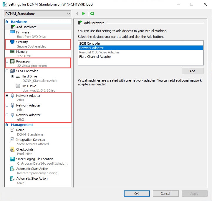
On the Select Networks screen, map the networks that are used in the OVF template to networks in your inventory.
However, you can edit the network properties after installation, if required, using the appmgr update network-properties command. For more information, see Editing Network Properties Post DCNM Installation. From the Destination Network drop-down list, choose to associate the network mapping with the port group that corresponds to the subnet that is associated with the corresponding network. If you are deploying more than one DCNM Open Virtual Appliance for HA functionality, you must meet the following criteria:
Click Next. |
||
| Step 12 |
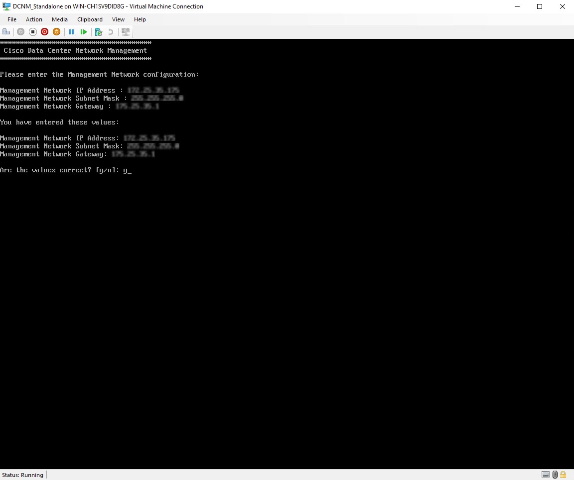
On Customize template screen, enter the Management Properties information. Enter the IP Address (for the outside management address for DCNM), Subnet Mask, and Default Gateway.
Ensure that add valid values for the Management Network properties. Properties with invalid values will not be assigned. The VM will not power on until you enter valid values. From Release 11.3(1), for Huge and Compute configurations, you can add extra disk space on the VM. You can add from 32GB up to 1.5TB of disk space. In the Extra Disk Size field, enter the extra disk size that will be created on the VM. Click Next. |
||
| Step 13 |
On Ready to Complete screen, review the deployment settings. Click Back to go to the previous screens and modify the configuration. Click Finish to deploy the OVF template. You can see the deployment status in the Recent Tasks area on the vSphere Client.
|
||
| Step 14 |
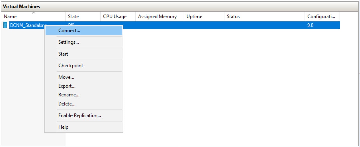
After the installation is complete, right click on the installed VM and select Power > Power On.
You can see the status in the Recent Tasks area. |
||
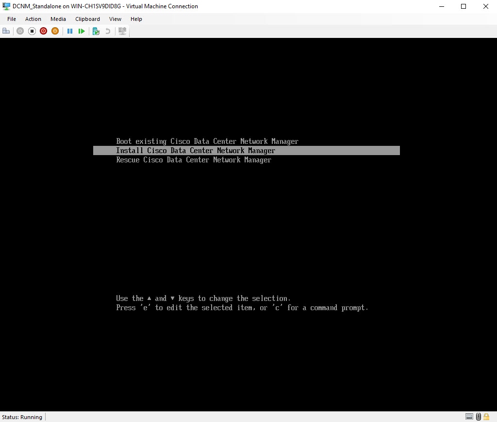
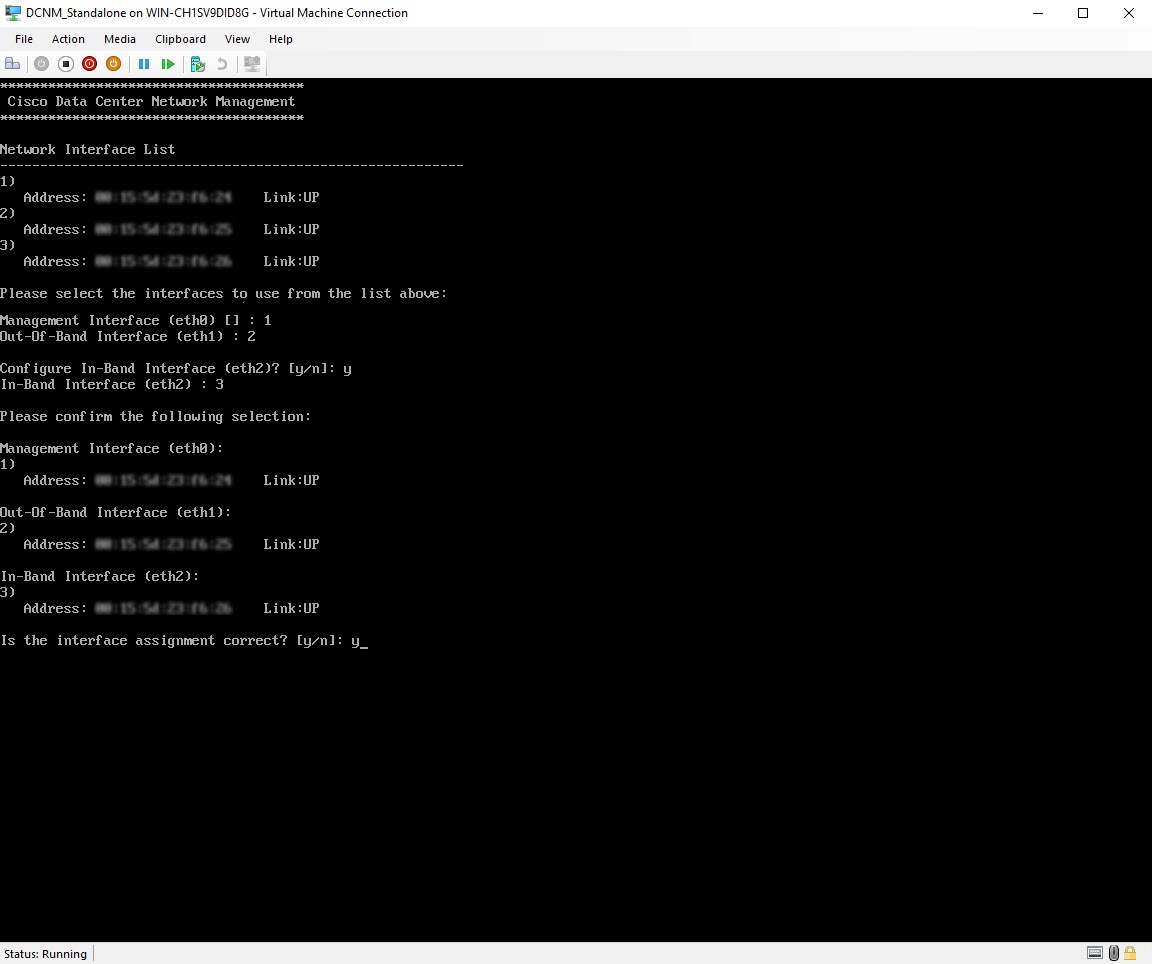
| Step 15 |
Navigate to the Summary tab and click Settings icon and select Launch Web Console. A message indicating that the DCNM appliance is configuring appears on the screen. Copy and paste the URL to the browser to complete the installation, using the Web Installer. |
What to do next
You can choose to install DCNM in Standalone mode or Native HA mode. For more information, see Installing the Cisco DCNM OVA in Standalone Mode or Installing the Cisco DCNM OVA in Native HA mode.
Installing the Cisco DCNM OVA in Standalone Mode
Paste the URL displayed on the Console tab and hit Enter key. A welcome message appears.
To complete the installation of Cisco DCNM from the web installer, perform the following procedure.
Procedure
| Step 1 |
On the Welcome to Cisco DCNM screen, click Get Started.
|
||||
| Step 2 |
On the Cisco DCNM Installer tab, select Fresh Installation – Standalone radio button. Click Next. |
||||
| Step 3 |
On the Install Mode tab, choose your DCNM deployment type. From the Installation mode drop-down list, choose LAN Fabric installation mode for the DCNM Appliance. Check the Enable Clustered Mode check box, if you want to deploy Cisco DCNM in Cluster mode. The Compute nodes will be displayed on the Cisco DCNM Web UI > Applications > Compute. The applications will run on the Compute nodes. You can add the compute nodes to a Cluster, later.
Click Next. |
||||
| Step 4 |
On the Administration tab, enter information about passwords.
Select the Show passwords in clear text check box to view the password that you have entered. Click Next. |
||||
| Step 5 |
On the System Settings, configure the settings for the DCNM Appliance.
Click Next. |
||||
| Step 6 |
On the Network Settings tab, configure the network parameters used to reach the DCNM Web UI. 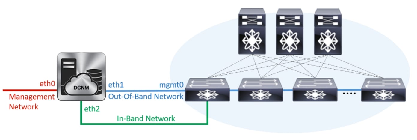
However, you can edit the network properties after installation, if required, using the appmgr update network-properties command. For more information, see Editing Network Properties Post DCNM Installation. Click Next. |
||||
| Step 7 |
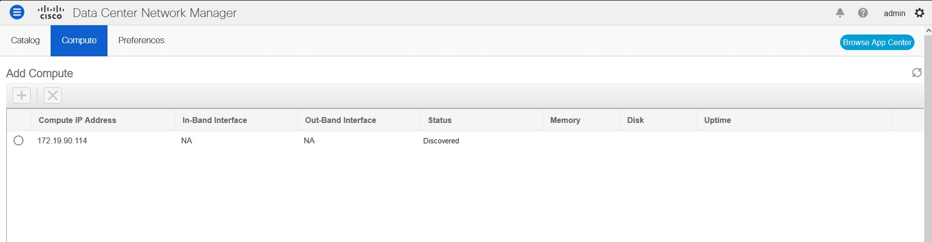
On the Applications tab, configure the Device Connector and Internal Applications Services Network, and Cluster mode settings.
The Device connector is an embedded management controller that enables the capabilities of Cisco Intersight, a cloud-based management platform. Click Next. |
||||
| Step 8 |
On the Summary tab, review the configuration details. Click Previous to go to the previous tabs and modify the configuration. Click Start Installation to complete the Cisco DCNM Installation for the chosen deployment mode. A progress bar appears showing the completed percentage, description of the operation, and the elapsed time during the installation. After the progress bar shows 100%, click Continue. A success message appears with the URL to access DCNM Web UI.
|
What to do next
Log on to the DCNM Web UI with appropriate credentials.
Click the Settings icon and choose About DCNM. You can view and verify the Installation type that you have deployed.
dcnm# appmgr update network-properties add route ipv4 eth2 <ipv4-network-ip-address/prefix>dcnm# appmgr update network-properties session start
dcnm# appmgr update network-properties add route ipv4 eth2 10.0.0.0/24
dcnm# appmgr update network-properties add route ipv4 eth2 40.1.1.0/24
dcnm# appmgr update network-properties session applyInstalling the Cisco DCNM OVA in Native HA mode
The native HA is supported on DCNM appliances with ISO or OVA installation only.
By default, an embedded PostgreSQL database engine with the Cisco DCNM. The native HA feature allows two Cisco DCNM appliances to run as active and standby applications, with their embedded databases synchronized in real time. Therefore, when the active DCNM is not functioning, the standby DCNM takes over with the same database data and resume the operation.
Perform the following task to set up Native HA for DCNM.
Procedure
| Step 1 |
Deploy two DCNM Virtual Appliances (either OVA or ISO). For example, let us indicate them as dcnm1 and dcnm2. |
||||||||||
| Step 2 |
Configure dcnm1 as the Primary node. Paste the URL displayed on the Console tab of dcnm1 and press Enter key. A welcome message appears.
|
||||||||||
| Step 3 |
Configure dcnm2 as the Secondary node. Paste the URL displayed on the Console tab of dcnm2 and hit Enter. A welcome message appears.
|
What to do next
Log on to the DCNM Web UI with appropriate credentials.
Click the Settings icon and choose About DCNM. You can view and verify the Installation type that you have deployed.
dcnm# appmgr update network-properties add route ipv4 eth2 <ipv4-network-ip-address/prefix>For example: If you have four switches with all fabric links connected through 10.0.0.x/30 subnet, and if all switches are configured with the loopback interface for inband reachability in subnet 40.1.1.0/24, use the following commands:
dcnm# appmgr update network-properties session start
dcnm# appmgr update network-properties add route ipv4 eth2 10.0.0.0/24
dcnm# appmgr update network-properties add route ipv4 eth2 40.1.1.0/24
dcnm# appmgr update network-properties session apply

 Feedback