The fields that appear in the Create Route Peering window depend
on the type of deployment chosen in the Create Service Node
window. Depending on the type chosen (Firewall or Load Balancer), the types of
deployments are Intra-Tenant Firewall, Inter-Tenant Firewall, One-Arm load balancer and
Two-Arm load balancer.

Note |
Deletion of service network is not supported in Top-down provisioning.
|
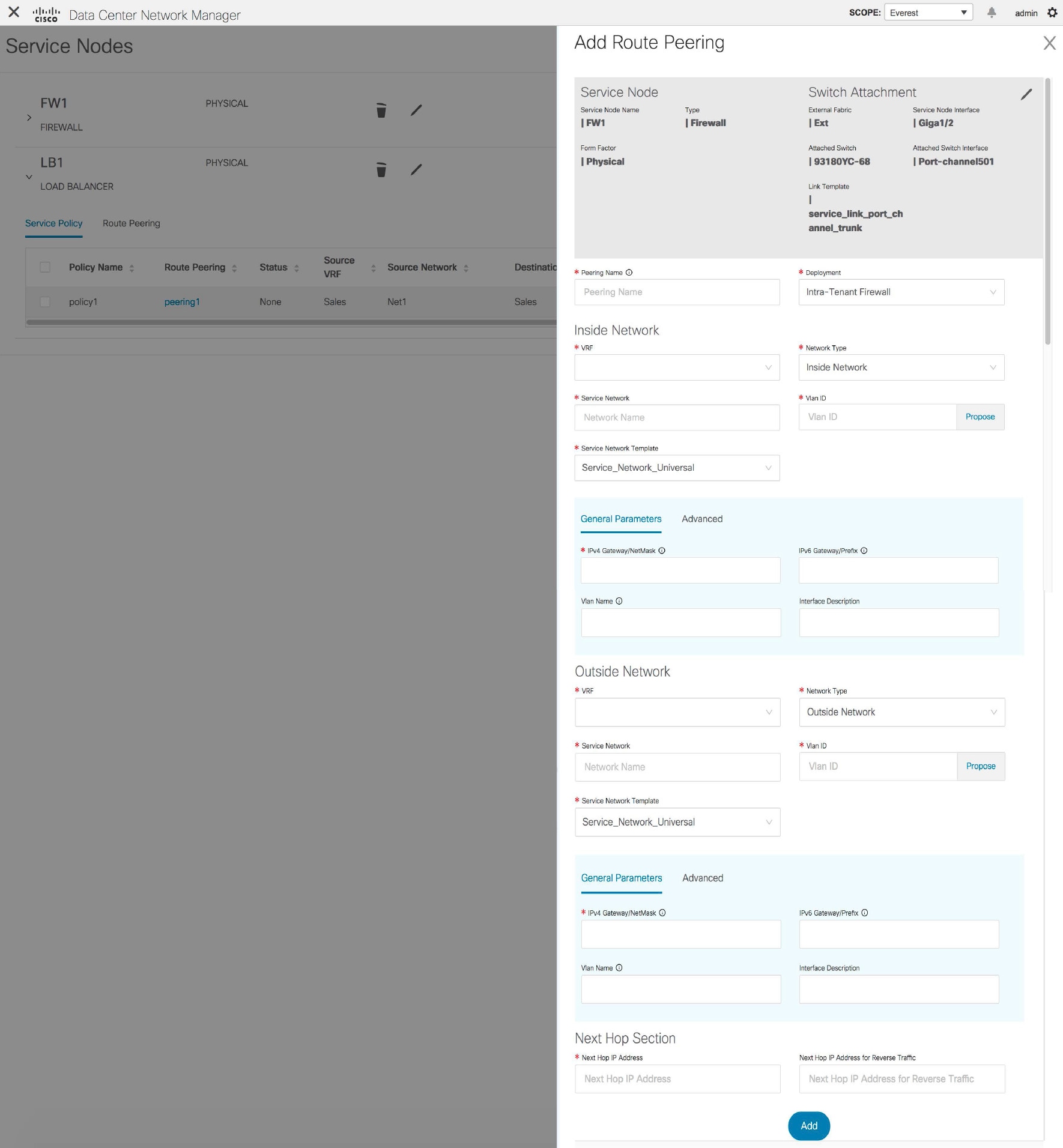
Example: Intra-Tenant Firewall Deployment
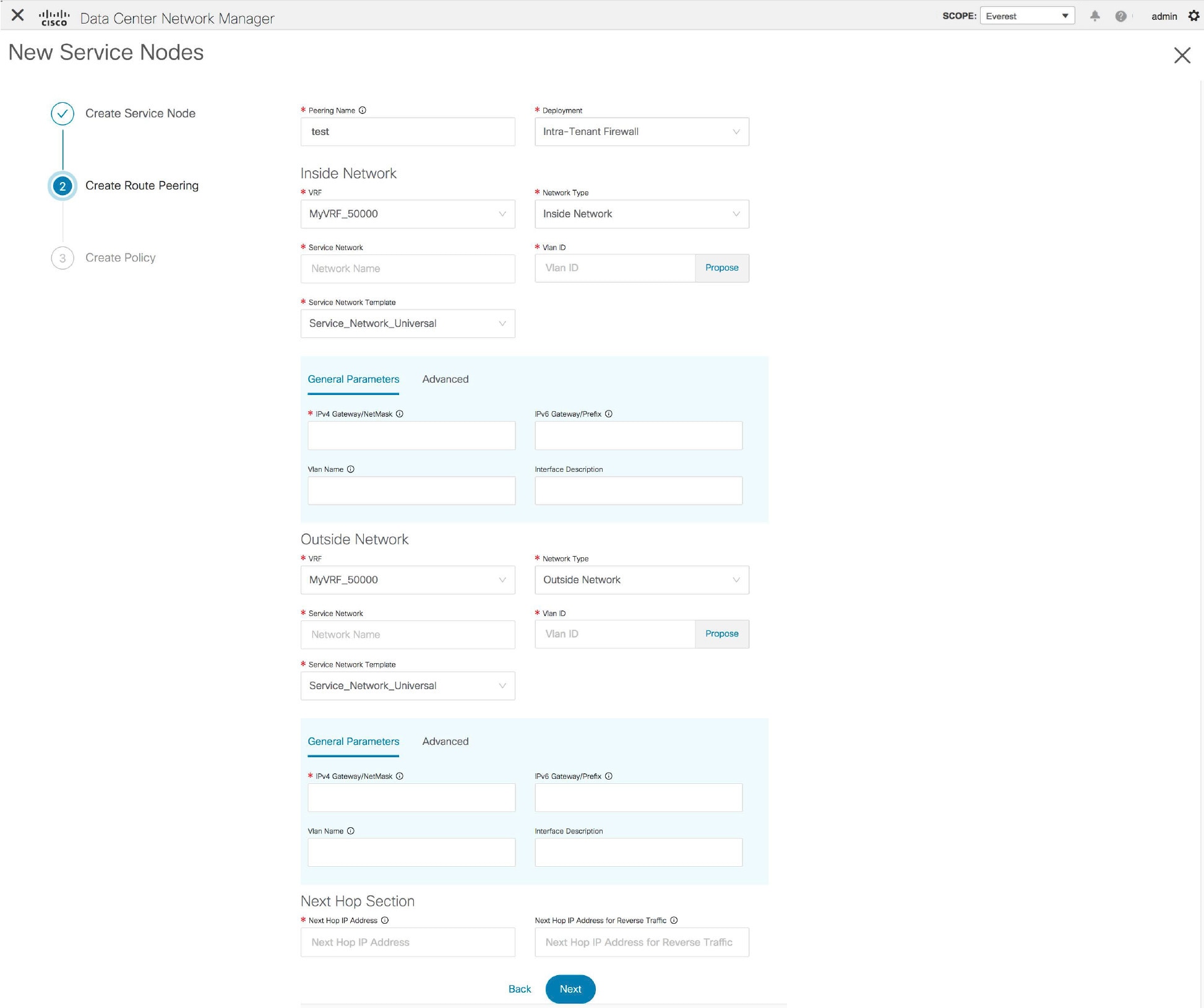
The fields in the Create
Route Peering window for an Intra-Tenant Firewall deployment are as
given below. It is mandatory to fill the fields marked with an asterisk. For more
information on the fields in this window, hover over the i
icon.
Peering Name - Specify a name for the peering.
The name can have alphanumeric, underscore, or dash
characters.
Deployment - Select Intra-Tenant
Firewall.
Inside Network
VRF - Specify the VRF.
Network Type - Select Inside Network.
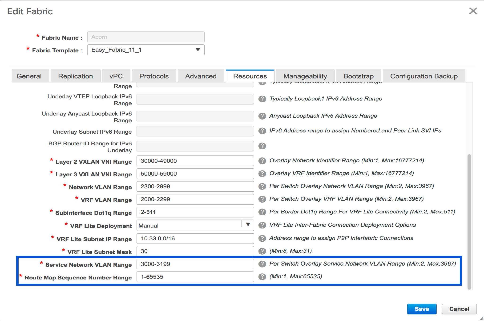
Service Network - Specify the name of the service network.
Vlan ID - Specify the VLAN ID. Valid IDs range from 2 to 3967.
Click Propose to retrieve a value from the pre-defined service network VLAN range
pool.
Service Network Template - Select the
Service_Network_Universal template from the drop-down list. For more information on
the template fields, refer Templates.
Outside Network
VRF - Specify the VRF.
Network Type - Select Outside Network.
Service Network - Specify the name of the service network.
Vlan ID - Specify the VLAN ID. Valid IDs range from 2 to 3967.
Click Propose to retrieve a value from the pre-defined service network VLAN range
pool.
Service Network Template - Select the
Service_Network_Universal template from the drop-down list. For more information on
the template fields, refer Templates.
Next Hop Section
Next Hop IP Address - Specify the next-hop IP address. This is
the IP/VIP of the service node used for traffic redirection.
Next Hop IP Address for Reverse Traffic - Specify the next-hop
IP address for reverse traffic. This is the IP/VIP of the service node used for
traffic redirection.
Example: Inter-Tenant Firewall Deployment
Peering Option - Static Peering, Inside Network Peering Template -
service_static_route, Outside Network Peering Template -
service_static_route
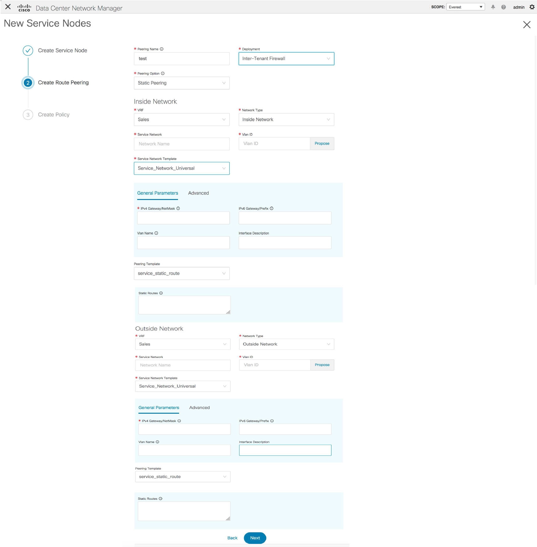
The fields in the Create Route Peering
window for an Inter-Tenant Firewall deployment are as given below. It is mandatory
to fill the fields marked with an asterisk.
Peering
Name - Specify a name for the peering. The name can have
alphanumeric, underscore, or dash characters.
Deployment - Select Inter-Tenant
Firewall.
Peering Option - Select Static Peering or
eBGP Dynamic Peering.
Inside Network
VRF - Select a VRF from the drop-down list..
Network Type - Select Inside Network.
Service Network - Select a service network name from the
drop-down list.
Vlan ID - Specify the VLAN ID. Valid IDs range from 2 to 3967.
Click Propose to retrieve a value from the pre-defined
service network VLAN range pool.
Service Network Template - Select the
Service_Network_Universal template from the drop-down list. For more information on
the template fields, refer Templates.
Peering Template - Select service_static_route or
service_ebgp_route from the drop-down list. For more information on the template
fields, refer Templates.
Outside Network
VRF - Select a VRF from the drop-down list..
Network Type - Select Outside Network.
Service Network - Select a service network name from the
drop-down list.
Vlan ID - Specify the VLAN ID. Valid IDs range from 2 to 3967.
Click Propose to retrieve a value from the pre-defined
service network VLAN range pool.
Service Network Template - Select the
Service_Network_Universal template from the drop-down list. For more information on
the template fields, refer Templates.
Peering Template - Select service_static_route or
service_ebgp_route from the drop-down list. For more information on the template
fields, refer Templates.
Note |
Inter-tenant firewall deployment with eBGP dynamic peering option is not
supported.
|
Example: One-Arm Mode Load Balancer
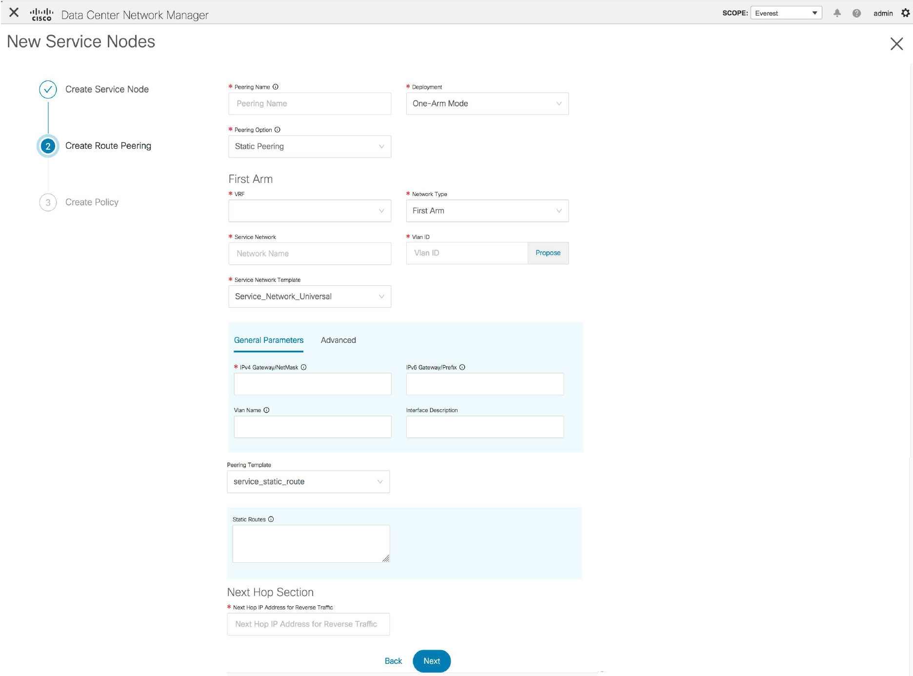
The fields in the Create
Route Peering window for a One-Arm Mode load balancer deployment are
as given below. It is mandatory to fill the fields marked with an asterisk.
Peering Name - Specify a name for the peering. The
name can have alphanumeric, underscore, or dash
characters.
Deployment - Select One-Arm Mode.
Peering Option - Select Static Peering or eBGP
Dynamic Peering.
First Arm
VRF - Select a VRF from the drop-down list..
Network Type - Select First Arm.
Service Network - Select a service network name from the
drop-down list.
Vlan ID - Specify the VLAN ID. Valid IDs range from 2 to 3967.
Click Propose to retrieve a value from the pre-defined
service network VLAN range pool.
Service Network Template - Select the
Service_Network_Universal template from the drop-down list. For more information on
the template fields, refer Templates.
Peering Template - Select service_static_route or
service_ebgp_route from the drop-down list. For more information on the template
fields, refer Templates.
Next Hop IP Address for Reverse Traffic - Specify the next-hop
IP address for reverse traffic.
Example: Two-Arm Mode Load Balancer
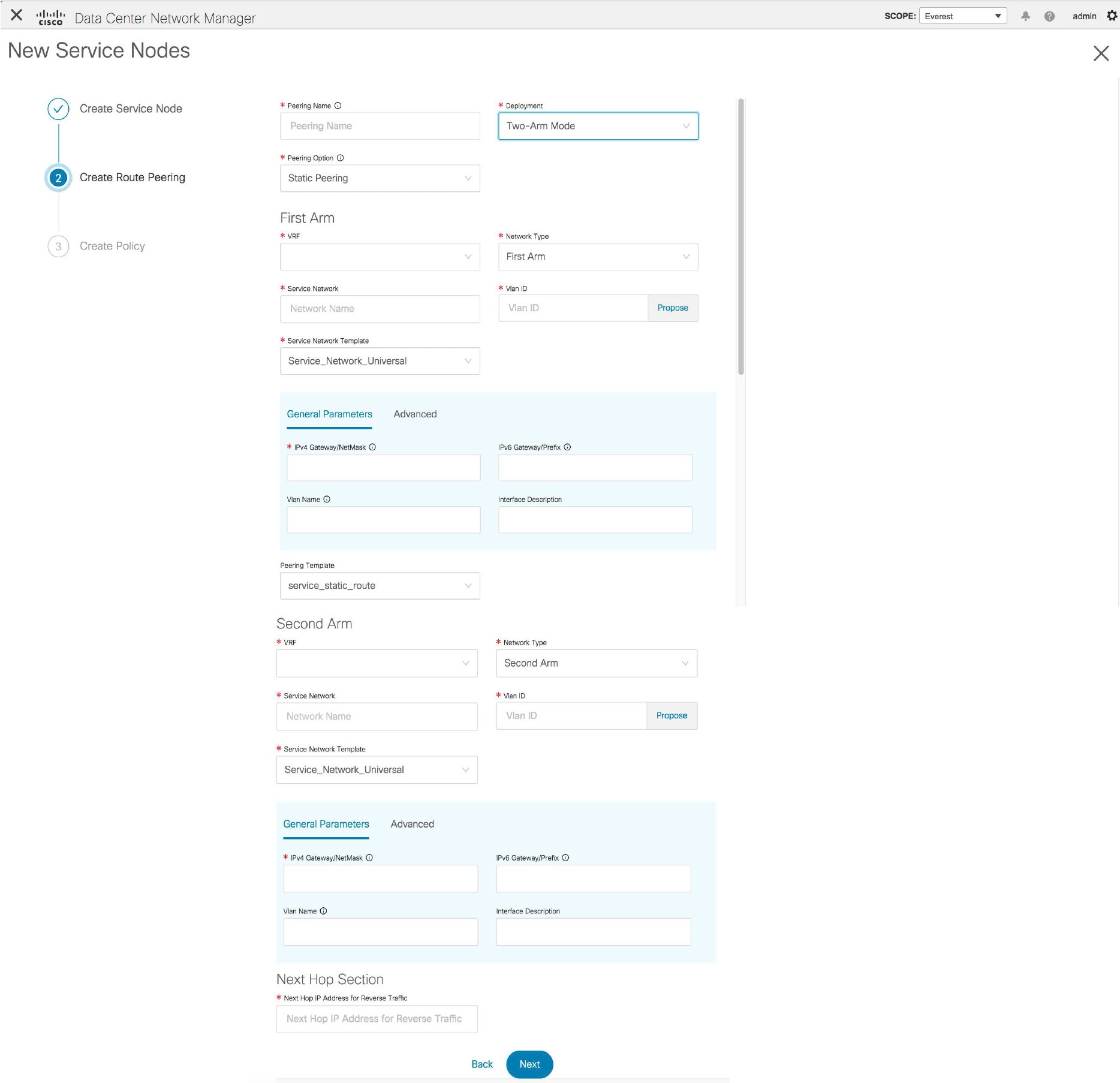
The fields in the Create Route Peering
window for a Two-Arm Mode load balancer deployment are as given below. It is
mandatory to fill the fields marked with an asterisk.
Peering
Name - Specify a name for the peering. The name can have
alphanumeric, underscore, or dash
characters.
Deployment - Select Two-Arm
Mode.
Peering Option - Select Static Peering or
eBGP Dynamic Peering.
First Arm
VRF - Select a VRF from the drop-down list..
Network Type - Select First Arm.
Service Network - Select a service network name from the
drop-down list.
Vlan ID - Specify the VLAN ID. Valid IDs range from 2 to 3967.
Click Propose to retrieve a value from the pre-defined
service network VLAN range pool.
Service Network Template - Select the
Service_Network_Universal template from the drop-down list. For more information on
the template fields, refer Templates.
Peering Template - Select service_static_route or
service_ebgp_route from the drop-down list. For more information on the template
fields, refer Templates.
Second Arm
VRF - Select a VRF from the drop-down list..
Network Type - Select Second Arm.
Service Network - Specify the name of the service network.
Vlan ID - Specify the VLAN ID. Valid IDs range from 2 to 3967.
Click Propose to retrieve a value from the pre-defined
service network VLAN range pool.
Service Network Template - Select the
Service_Network_Universal template from the drop-down list. For more information on
the template fields, refer Templates.
Next Hop Section
Next Hop IP Address for Reverse Traffic - Specify the next-hop
IP address for reverse traffic.
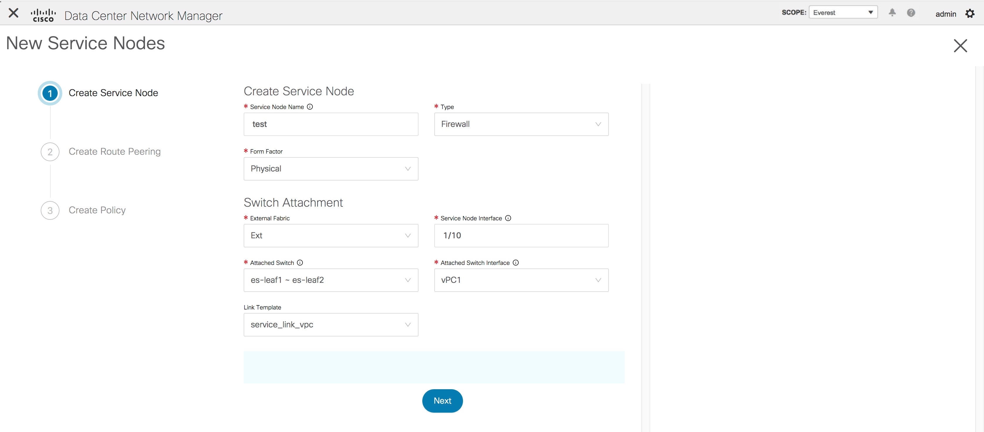
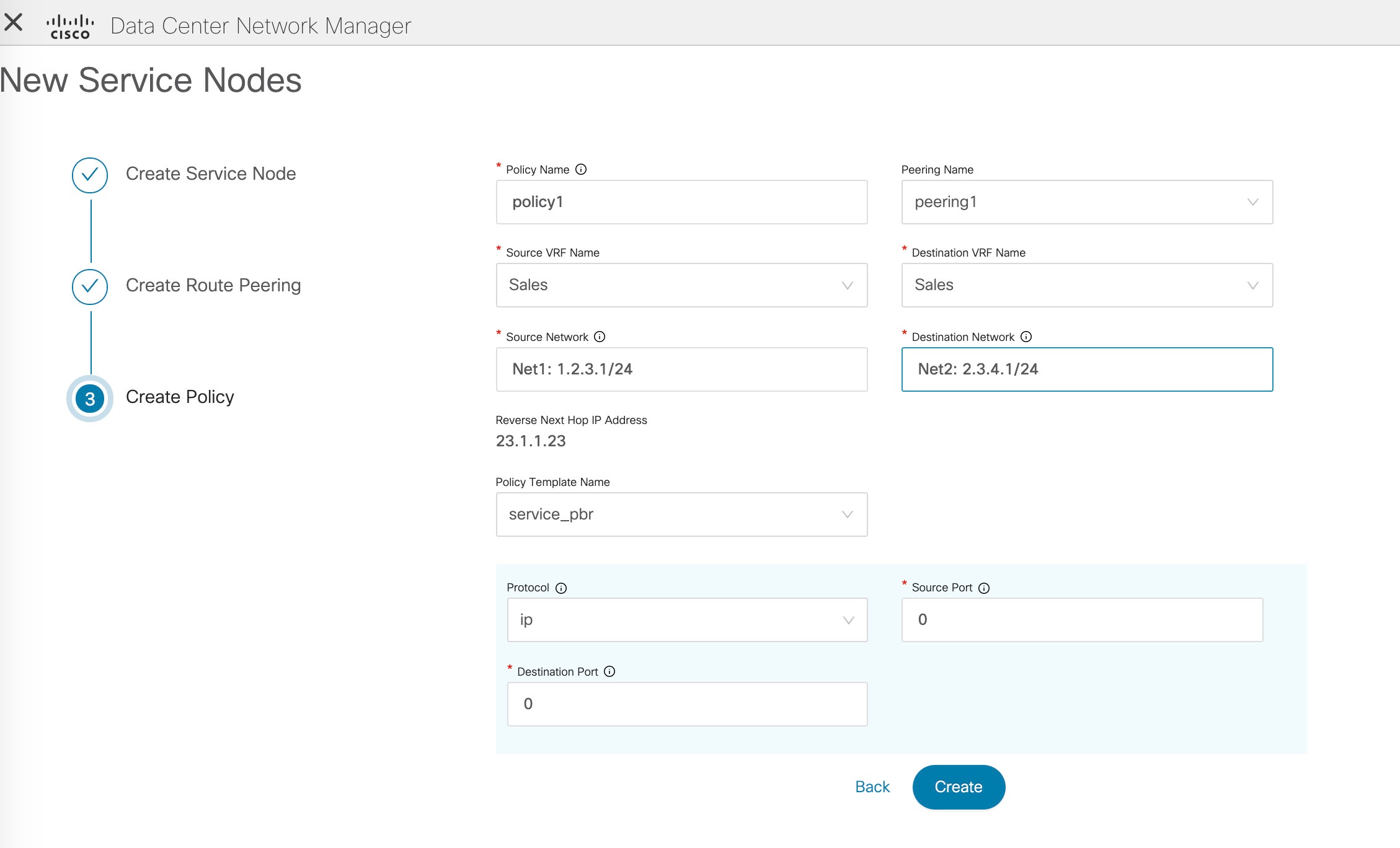
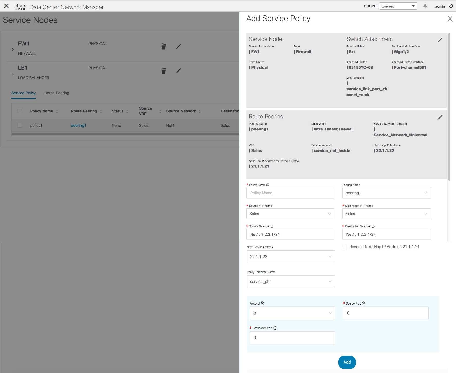
Now, click Next. The Create Policy
window is displayed.

 Feedback