You can connect non-VXLAN BGP EVPN (legacy) and VXLAN BGP EVPN fabrics by positioning a set of VTEPs external to the fabric.
Such VTEPs are called pseudo-BGWs. This topic explains how to set up a pseudo-BGW through DCNM 11.1(1). For more information
on legacy site integration, refer the Legacy Site Integration section in the VXLAN EVPN Multi-Site Design and Deployment White Paper document.
It is assumed that the legacy network is setup and functional. The procedure and method used for setting up the legacy network
is out of the scope of this document.
Reference Topology
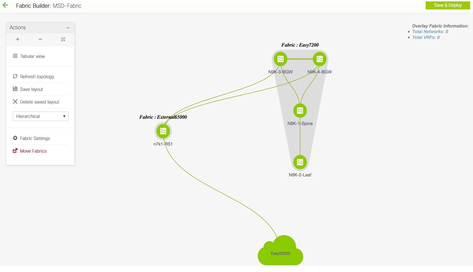
The image shows the portion of the topology that includes the route servers RS_1 and RS_2 (imported into external fabrics), pseudo-BGWs A-LEAF9 and A-LEAF10 in the PSEUDO_BGW fabric, and the legacy fabric named LEGACY. Each fabric and their connectivity is explained.
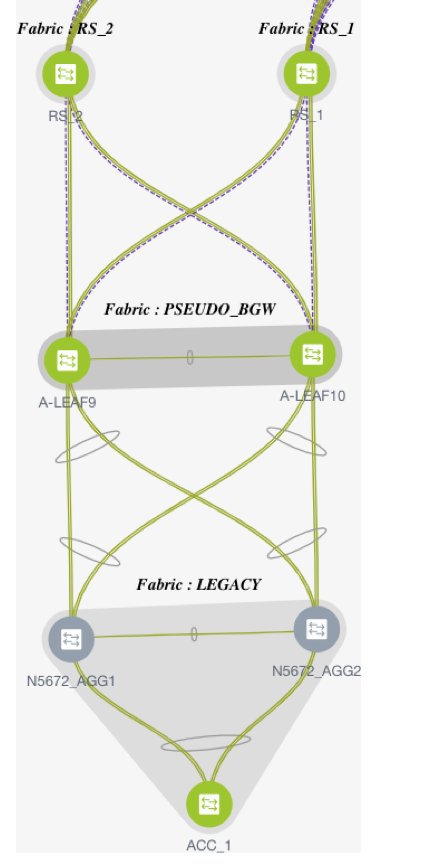
Route Servers
RS_1 and RS_2 are connected to a VXLAN BGP EVPN fabric (located above the route servers, not seen in the above image. This connection is
configured as described in the standard Multi-Site configuration section).
RS_1 and RS_2 are connected to the pseudo-BGWs (A-LEAF9 and A-LEAF10) directly below them, through Multi-Site inter-fabric connections (IFCs).
Pseudo-BGWs
A-LEAF9 and A-LEAF10 are pseudo-BGWs in the PSEUDO_BGW VXLAN fabric. They are configured as a vPC switch pair, with the vPC formed towards the directly connected devices in the
LEGACY fabric, to its south.
Legacy Fabric
The switches in the legacy network are imported into a dedicated external fabric in Monitor mode.

Note |
When an external fabric is set to Fabric Monitor Mode Only, you cannot deploy configurations on its switches. Refer the Creating an External Fabric topic in the Control chapter for details.
|
The Deploying Pseudo-BGW topic covers these configurations:
Step 1 - Configuring the PSEUDO_BGW VXLAN Fabric
Step 2 - Creating Multi-Site underlay eBGP IFCs from the pseudo-BGWs to the route servers.
Step 3 - Creating Multi-Site overlay eBGP IFCs from the pseudo-BGWs to the route servers.
Detailed explanation
Step 1 - Configuring the PSEUDO_BGW VXLAN Fabric
The pseudo-BGWs are Cisco Nexus 9000 Series switches that are imported into DCNM. Enable the following configurations in the
PSEUDO_BGW fabric.
You must enable the Ingress replication mode for the PSEUDO_BGW fabric, assign the Leaf role for the pseudo-BGWs, configure the pseudo-BGWs as a vPC switch pair, and form the vPC towards the legacy fabric devices.
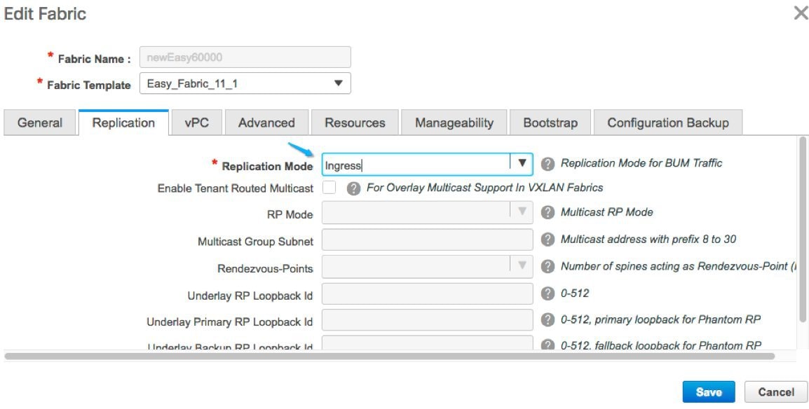
Enabling the Ingress Replication Mode
-
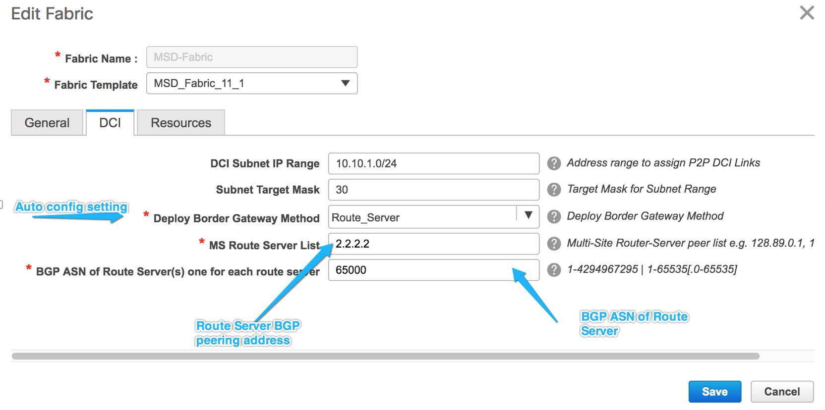
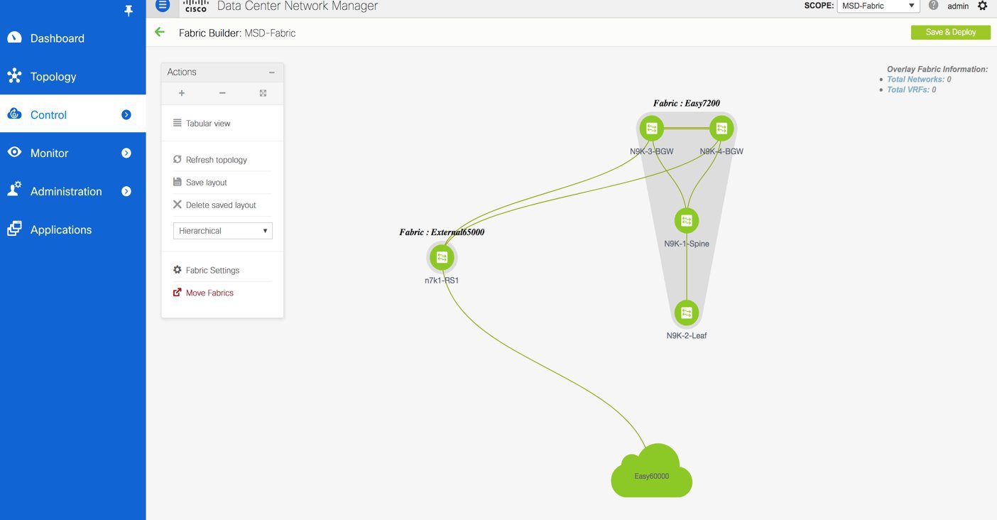
In the Fabric Builder screen, click the Edit Fabric icon for the fabric.
The Edit Fabric screen comes up
-
In the Replication tab, choose the Replication Mode option as Ingress.
Setting the Leaf Role For the Pseudo-BGWs
-
In the Fabric Builder screen, click the PSEUDO_BGW fabric.
The PSEUDO_BGW topology window appears.
-
Right-click A-LEAF9 and set its role as Leaf.
-
Right-click A-LEAF10 and set its role as Leaf.
Setting the Pseudo-BGWs as a vPC Switch Pair
-
Right-click the A-LEAF9 switch icon and choose vPC Pairing.
The list of potential vPC peer switches for A-LEAF9 comes up.
-
Click the radio button next to A-LEAF10 (the vPC peer switch) and click OK.
-
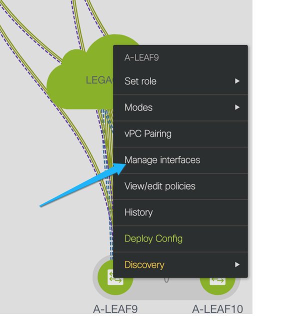
To set up the vPC towards the legacy fabric switches, right click the A-LEAF9 switch icon and choose Manage interfaces.
Similar flow is achieved through Control > Interfaces.
-
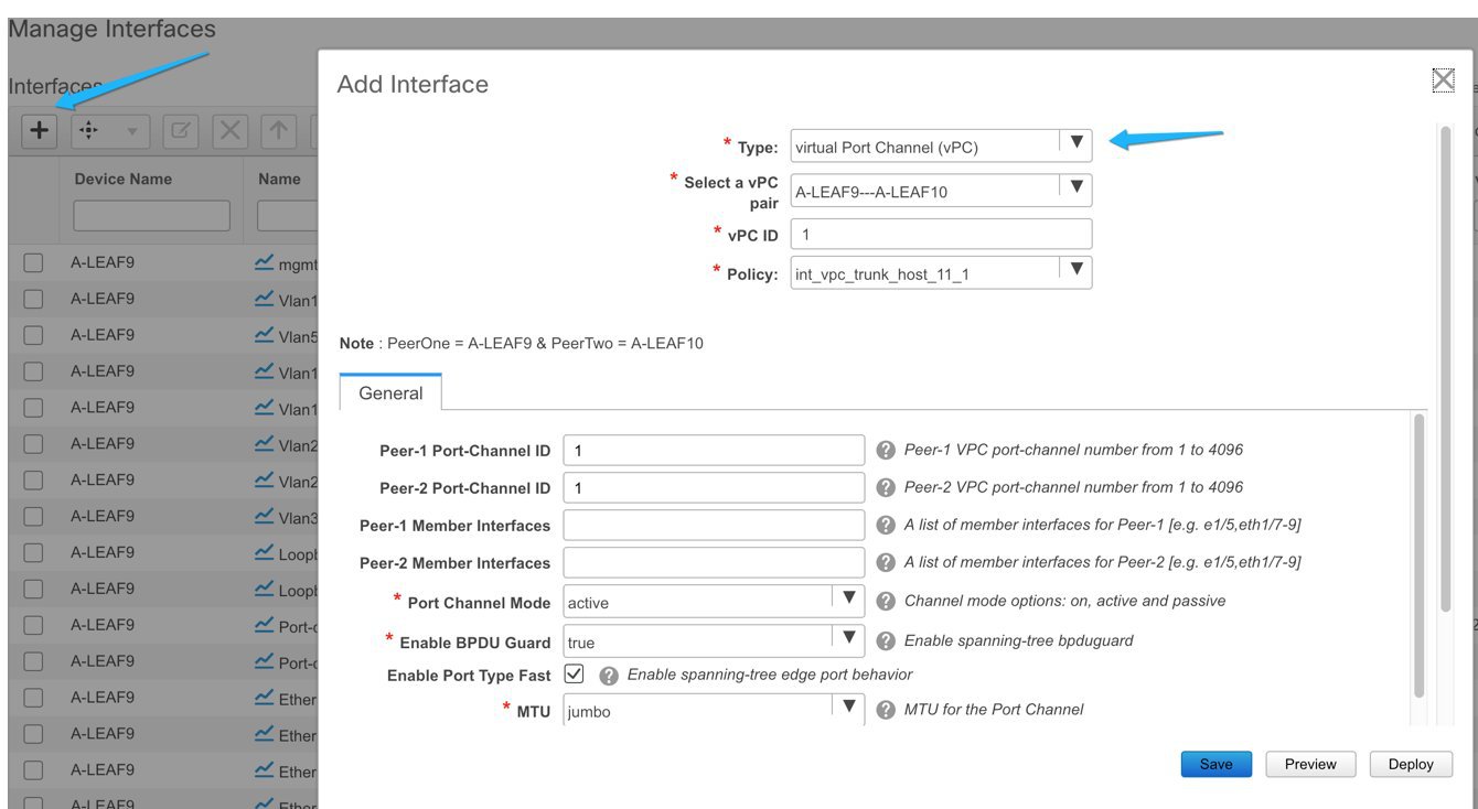
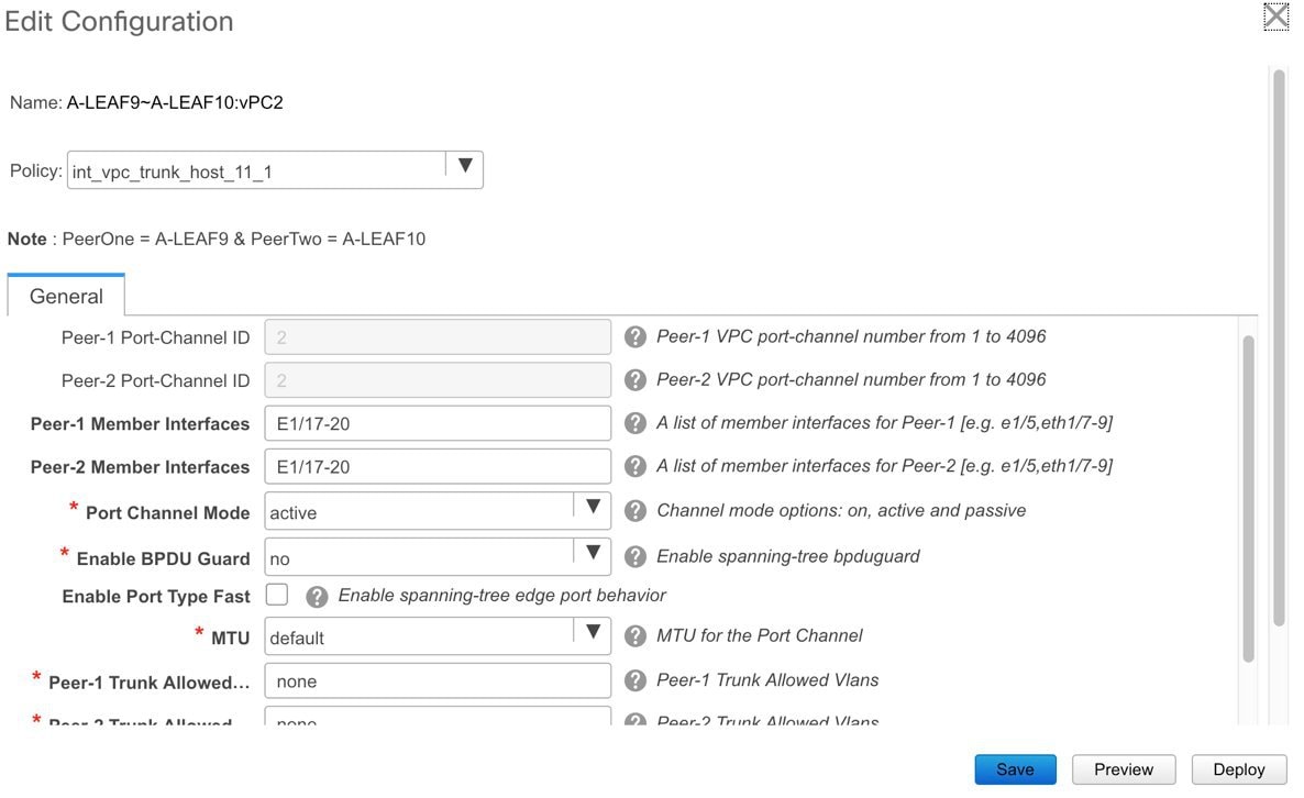
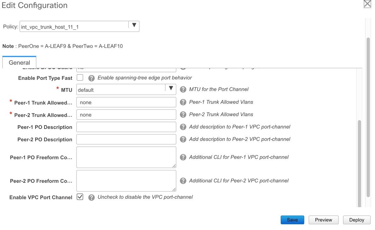
In the Manage Interfaces screen, click + and enter the fields as shown in the following example. From the drop-down list, choose the vPC policy and fill in the fields
for your topology.
-
Click Preview to see the configurations that are to be deployed. For this topology, the configurations are shown in the Appendix section.
-
Click Save to save the settings, and then Deploy to deploy the settings.
This completes the first task in the following configurations.
Step 1 - Configuring the PSEUDO_BGW VXLAN fabric
Step 2 - Creating Multi-Site underlay eBGP IFCs from the pseudo-BGWs to the route servers.
Step 3 - Creating Multi-Site overlay eBGP IFCs from the pseudo-BGWs to the route servers.
Next, the second step is explained.
Step 2 - Creating Multi-Site Underlay eBGP IFCs From the Pseudo-BGWs to the Route Servers
The Multi-Site underlay configuration shown here is similar to that of the MSD flow, except that switch freeform configurations
are used for adding network statements to distribute loopback0 and loopback1 (primary and secondary address) into the underlay
eBGP session towards the route server.
You can skip the Multi-Site underlay step in case your setup has a different method to distribute the loopback addresses to
the route servers or Core routers.
These tasks are performed from the VXLAN fabric, and the Save & Deploy operation is executed in the VXLAN and external fabrics.
In DCNM 11.1(1), configuring Multi-Site underlay IFCs is not mandatory for configuring Multi-Site overlay IFCs.
Step 2 comprises the following configuration tasks.
Configuring Multi-Site Underlay Session Through the DCNM GUI
In this example, one Multi-Site underlay is shown between RS_1 and A-LEAF9. Repeat the same process for every session required to a route server or Core router.
-
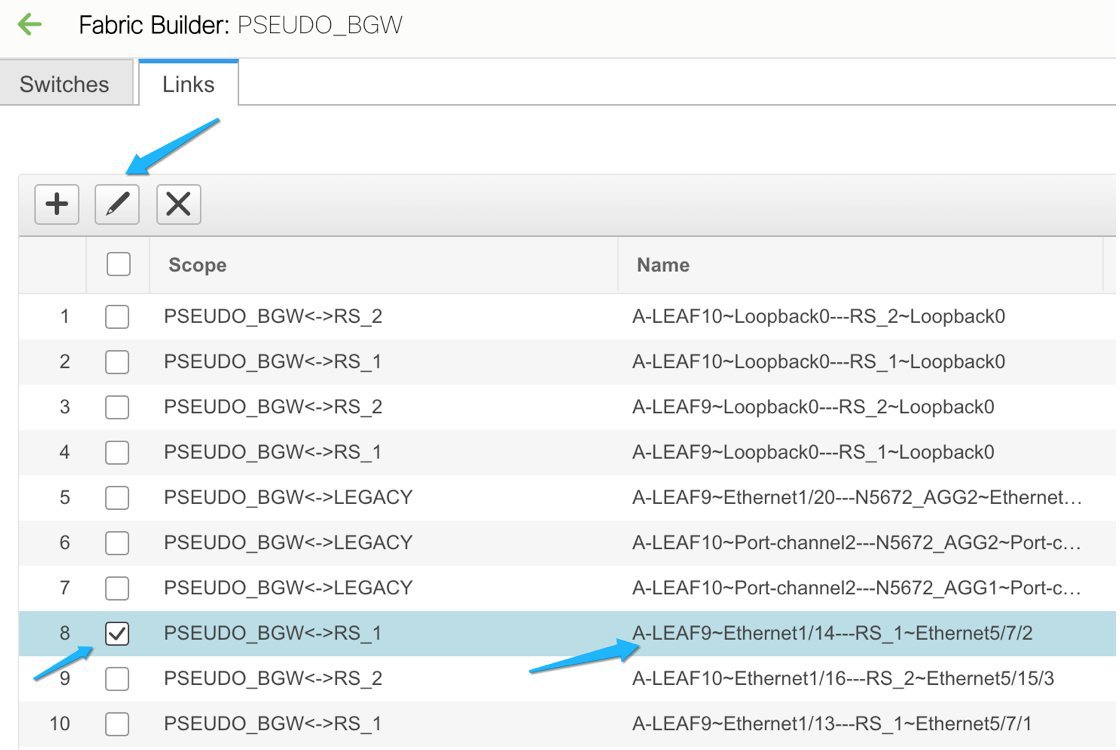
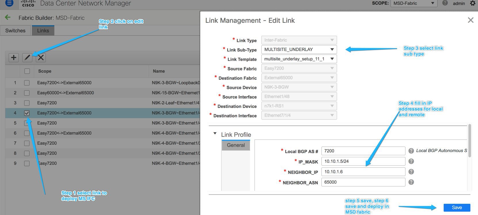
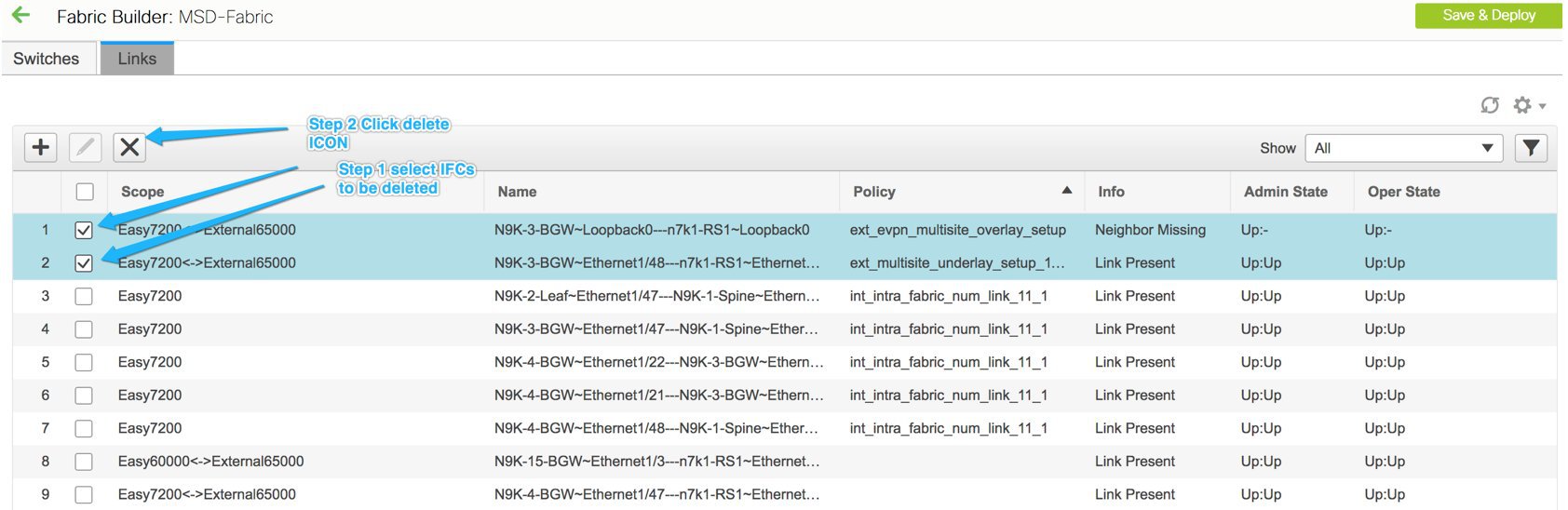
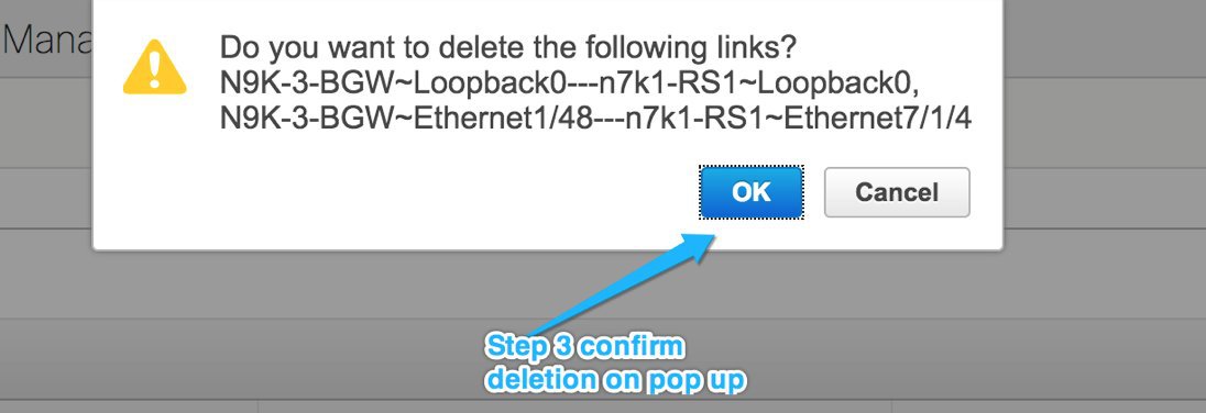
In the PSEUDO_BGW fabric, navigate to the Links tab.
-
Choose the check box corresponding to the physical connection between A-LEAF9 and RS_1, and click the Edit icon.
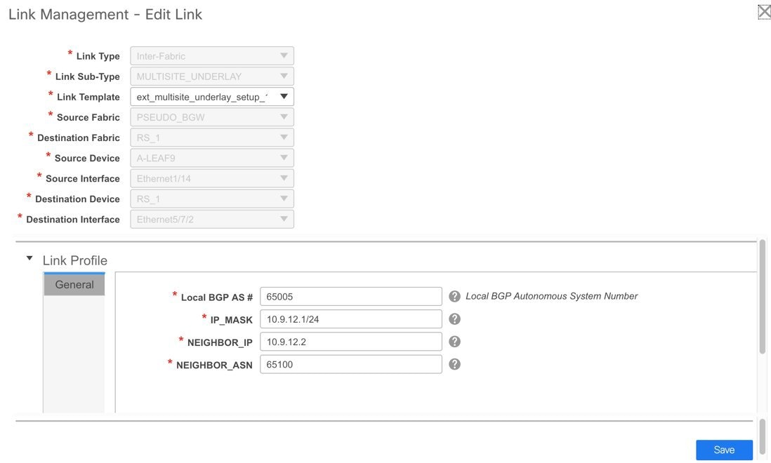
-
Fill in the fields.
This process is the same as the Multi-Site underlay IFC creation for an MSD fabric.
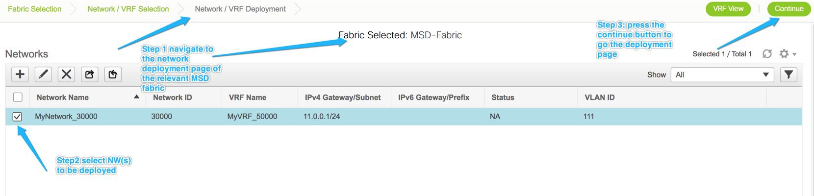
Configuring Networks Statements on Pseudo-BGWs
This is an additional step required on pseudo-BGWs.
For BGWs, DCNM 11.1(1) distributes the loopback addresses by tagging them and redistributing them into eBGP. This is only
available on BGWs, and not pseudo-BGWs.
Use the switch freeform policy to add network statements for loopback0, loopback 1 (primary and secondary IP addresses) under
the IPv4 address family, under the default routing table.
-
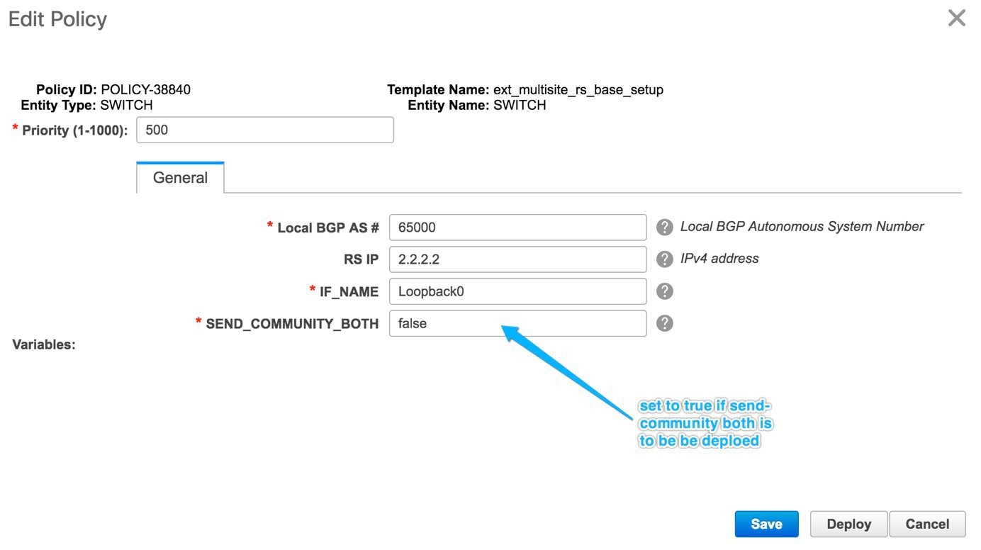
Right-click the switch icon and choose View/edit policies.
The View/Edit Policies screen comes up.
-
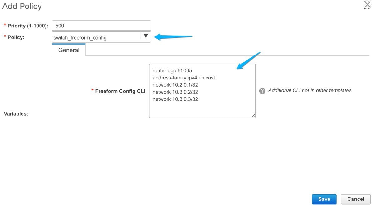
Click + at the top left part of the screen to add a policy.
The Add Policy screen comes up.
-
From the Policy drop-down list, choose switch_freeform_config.
-
In the Freeform Config CLI field, add the policy configurations.
This completes the second task in the following configurations.
Step 1 - Configuring the PSEUDO_BGW VXLAN fabric
Step 2 - Creating Multi-Site underlay eBGP IFCs from the pseudo-BGWs to the route servers.
Step 3 - Creating Multi-Site overlay eBGP IFCs from the pseudo-BGWs to the route servers.
The third step is explained below.
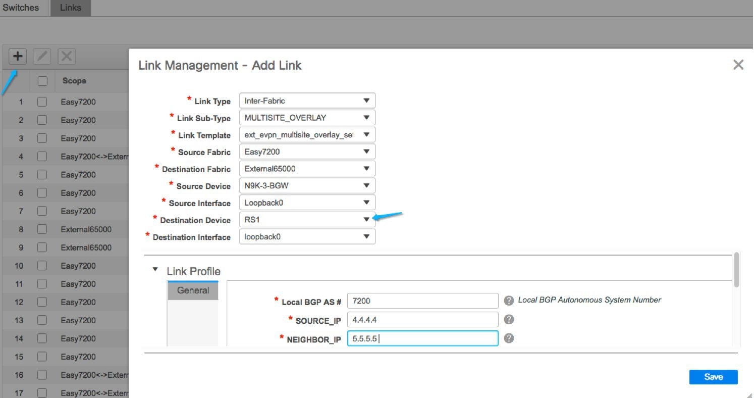
Step 3 - Creating Multi-Site Overlay eBGP IFCs from the Pseudo-BGWs to the Route Servers
Configuring Multi-Site overlay from pseudo-BGWs to the route server or directly to the BGW in the VXLAN fabric is similar.
-
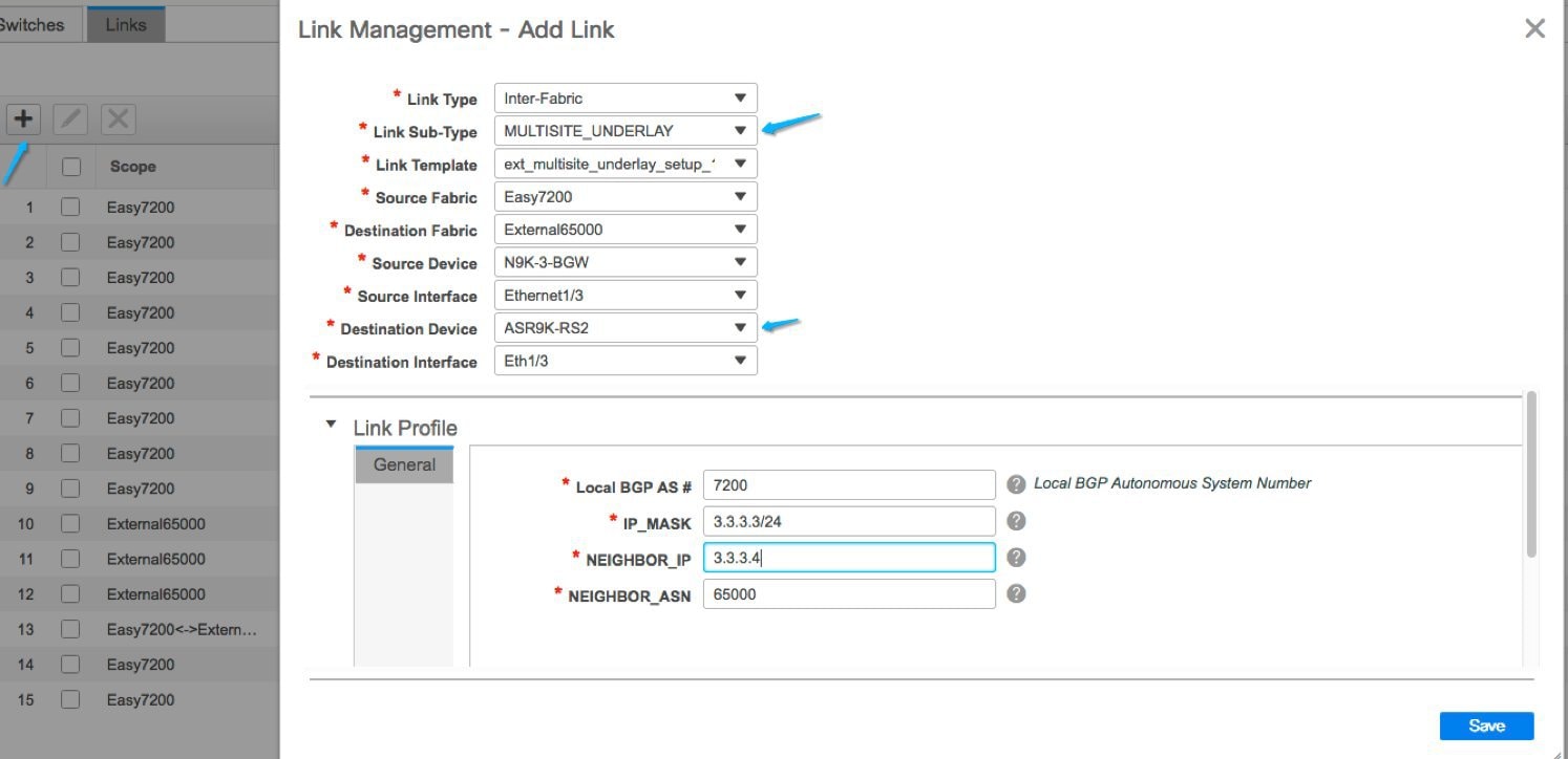
In the PSEUDO_BGW fabric, navigate to the Links tab.
-
Click + and fill the fields in the Add Link window.

-
Click Save at the bottom right part of the screen.
-
Execute the Save & Deploy operation in the VXLAN and external fabrics (VXLAN fabric for the Back-to-Back BGW case).


 Feedback