-
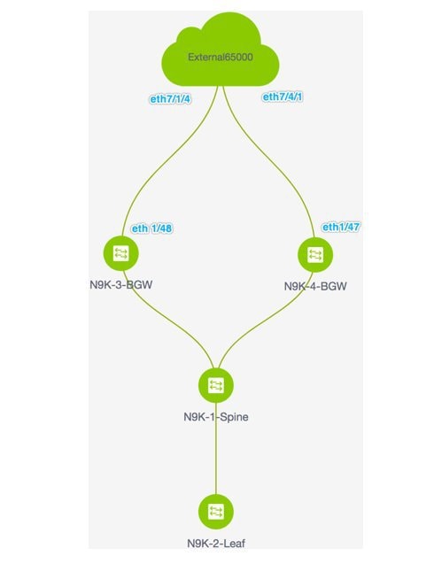
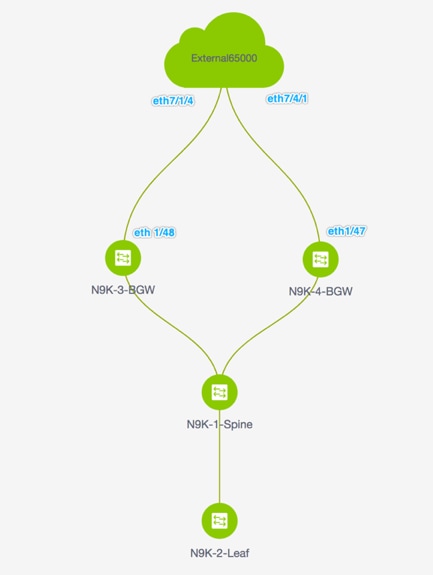
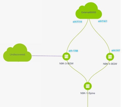
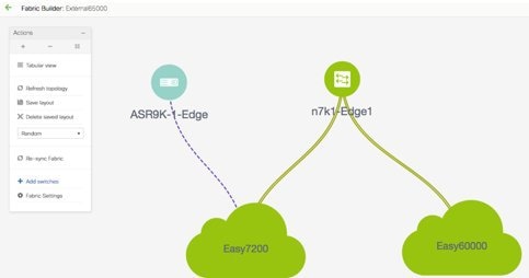
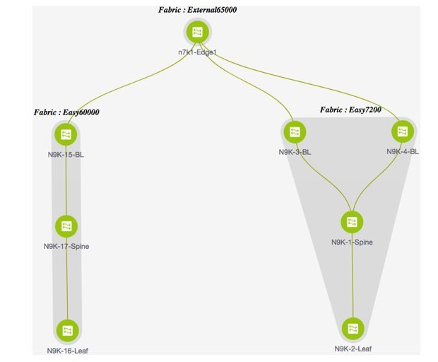
The topology displays the VXLAN BGP EVPN fabric Easy7200 connected to the external fabric External65000 (the cloud icon). The BGWs of the VXLAN fabric are connected to the edge router n7k1-Edge1 (not visible in the image) in the external fabric.
-
The BGWs are special devices that allow clear control and data plane segregation from the fabric domain to the external Layer
3 domain while allowing for policy enforcement points for any inter-fabric traffic. Network configurations for the VXLAN fabric
are provisioned through DCNM. For external Layer 3 reachability from hosts connected to leaf switches within the fabric, border
devices need to be provisioned with the appropriate VRF configuration. Multiple border devices in the fabric ensure redundancy
in the case of failures as well as effective load distribution. This document shows you how to enable Layer 3 north-south
traffic between the VXLAN fabric and the external fabric.
-
Before VRF Lite configuration, end hosts associated with a specific VRF can send traffic to each other, but only within the
fabric. After VRF Lite configuration, end hosts can send traffic outside the VXLAN fabric, towards other (VXLAN or classic
LAN) fabrics
Enabling the VRF Lite feature
For this example, we will enable connectivity between Easy7200 and External65000. The steps:
Step 1
- Deploy IFC prototypes on physical interfaces, on N9K-3-BGW and N9K-4-BGW.
Step 2 - Deploy the individual VRF extensions on the BGWs N9K-3-BGW and N9K-4-BGW.
Step 3 - Deploy VRF extensions on the edge router n7k1-Edge1.
The third step completes the configuration between Easy7200 and External65000.
Step 1 – Deploying IFC prototypes on physical interfaces on N9K-3-BGW and N9K-4-BGW
For VRF Lite configuration, you should enable eBGP peering between the fabric’s BGW interfaces and the edge router’s interfaces,
through point-to-point connections. The BGW physical interfaces are:
-
eth 1/48 on N9K-3-BGW, towards eth 7/1/4 on n7k1-Edge1.
-
eth 1/47 on N9K-4-BGW, towards eth 7/4/1 on n7k1-Edge1.

Note |
You can also enable VRF Lite in a back-to-back topology wherein Border/Border Gateways are directly connected to each other.
|
-
Click Control > Fabric Builder. The Fabric Builder screen comes up.
-
Click the Easy7200 box. The fabric topology comes up.
-
Click Tabular view. The Switches | Links screen comes up.
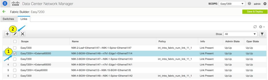
The Links tab lists fabric links. Each row either represents a link between two devices within Easy7200 or a link from a device in Easy7200 to an external fabric.
Note |
An inter-fabric link is a physical connection between two Ethernet interfaces or a virtual connection (such as a fabric overlay
between two loopback interfaces). When you add a physical connection between devices, the new link appears in the Links tab by default.
|
-
Select the link checkbox (that represents the connection between eth 1/48 on N9K-3-BGW, towards eth 7/1/4 on n7k1-Edge1) and click the Edit icon at the top left part of the screen.
The fields are:
Scope – The source and destination fabrics are displayed. For an intra-fabric link, only one fabric name (Easy7200) is displayed since the source and destination interfaces are part of the same fabric. An inter-fabric link is displayed
as Easy7200 <->External65000.
Name – The name is formed with the following syntax:
source device ~ source interface --- destination device ~ destination interface.
So, the entry is N9K-4-BGW ~ Ethernet1/47 --- n7k1-Edge1 ~ Ethernet7/4/1.
Policy – The policy used for creating VRF Lite, ext_fabric_setup_11_1 is displayed.
Info – This displays the status of the link (Link Present, Neighbor Present, Neighbor Missing, etc).
Admin State – This displays the administrative state of the link (Up, Down, etc).
Oper State – This displays the operational state of the link (Up, Down, etc).
The Link Management – Edit Link comes up.
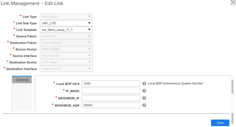
Some fields are explained:
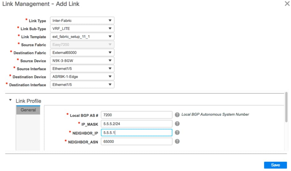
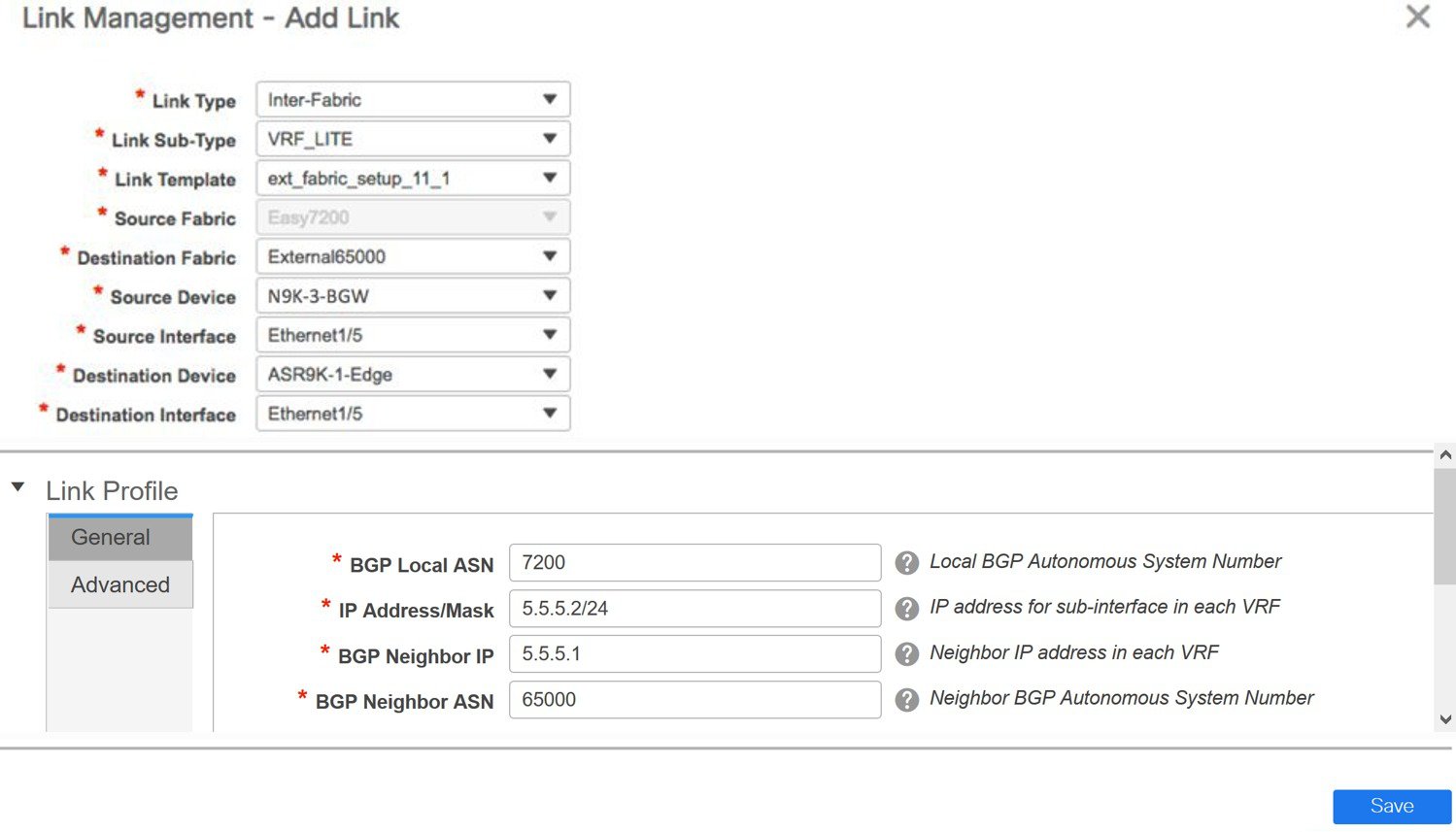
Link Sub-Type - By default, the VRF_LITE option is displayed.
Link Template – The default template for a VRF Lite IFC, ext_fabric_setup_11_1, is displayed. The template enables the source and destination interfaces as Layer 3 interfaces, configures the no shutdown command, and sets their MTU to 9216.
You can edit the ext_fabric_setup_11_1 template or create a new one with custom configurations.
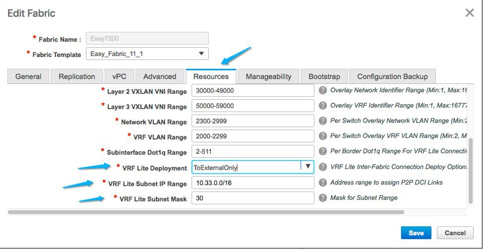
In the General tab, the BGP AS numbers of Easy7200 and External65000 are displayed. Fill in the other fields as explained.
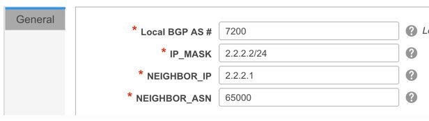
IP_MASK – Enter the IP address prefix to assign an IP address for the Ethernet 1/48 sub interfaces, the source interface of the IFC. A subinterface is associated for each VRF extended on this IFC, and a unique
802.1Q ID is assigned to it.
For example, an 802.1Q ID of 2 is associated with subinterface Eth 1/48.2 for VRF 50000 traffic, and 802.1Q ID of 3 is associated
with Eth 1/48.3 and VRF 50001, and so on.
(The VRF extension deployment is explained in a subsequent section).
The IP prefix is reserved with the DCNM resource manager. Ensure that you use a unique IP address prefix for each IFC you
create in the topology.
NEIGHBOR_IP – Enter the IP address of the eBGP neighbor for each VRF extension deployed on this IFC, on the N9K-3_BGW end.
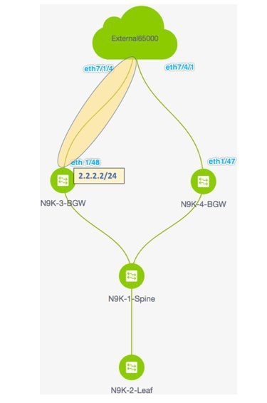
Inter-fabric traffic from VRFs for an IFC will have the same source IP address (2.2.2.2/24) and destination IP address (2.2.2.1).
-
Click Save at the bottom right part of the screen.
The Switches|Links screen comes up again. You can see that the IFC entry is updated with the VRF Lite policy template used for creating the
IFC, ext_fabric_setup_11_1. A representation of the topology is shown below.
-
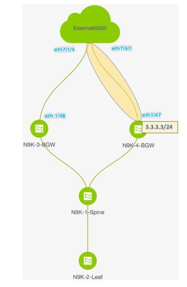
Similarly, create an IFC from eth 1/47 on N9K-4-BGW towards eth 7/4/1 on n7k1-Edge1. An entry is seen in the Links screen. A representation of the topology is shown below.
-
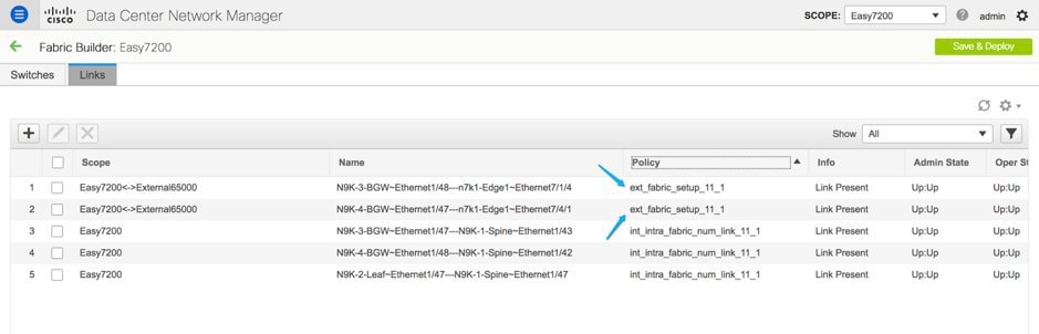
Click Save and Deploy at the top right part of the screen.
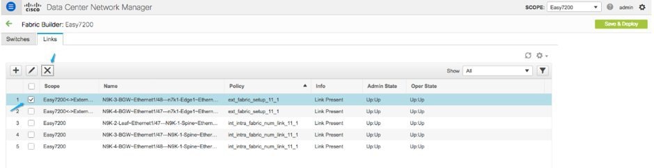
The Links tab after executing Save and Deploy looks like this. The links on which IFC has deployed have the relevant policy configured in the Policy column.
-
Go to the Scope drop down box at the top right part of the screen and choose External65000. The external fabric Links screen is displayed. You can see that the two IFCs created from Easy7200 to External65000 is displayed here.
Note |
When you create an IFC or edit its setting in the VXLAN fabric, the corresponding entry is automatically created in the connected
external fabric.
|
-
Click Save and Deploy to save the IFCs creation on External65000.
Base configurations – For VRF Lite to function, appropriate route maps and policies that apply to VRFs have to be deployed on the border devices
N9K-3-BGW and N9K-4-BGW. You do not need to manually enable the base configurations. They are automatically deployed via a default template ext_base_border_vrflite_11_1.
For a device with a Border Leaf or Border Spine role, the base configurations are deployed when you execute the Save and Deploy operation (available in the fabric topology screen [via the Fabric Builder screen > Fabric Box]) for the first time in a fabric.
For a Border Gateway or Border Gateway Spine role, the base configurations are deployed when you deploy the first VRF Lite
IFC on the device.
You can edit the ext_base_border_vrflite_11_1 template for specific needs, but only before you deploy a template instance. The configurations are noted in the Appendix section.
The first step in the VRF Lite configuration scenario, creating IFCs on the border devices and edge router, is complete. Next,
the VRF extensions are deployed on the switches.
Step 1 - Deploy IFC prototypes on physical interfaces, on N9K-3-BGW and N9K-4-BGW.
Step 2
- Deploy the individual VRF extensions on the BGWs N9K-3-BGW and N9K-4-BGW.
Step 3 - Deploy VRF extensions on the edge router n7k1-Edge1.
The third step completes the configuration between Easy7200 and External65000.
Step 2 - Deploy the individual VRF extensions on the BGWs N9K-3-BGW and N9K-4-BGW
During the IFC creation process, base configurations are created, and IP addresses are reserved for the interfaces that transport
the inter-fabric traffic on N9K-3-BGW and N9K-4-BGW. In this step, the VRF and VRF extension configuration is deployed on the interfaces.
To extend VRFs beyond the fabric, the VRFs should have been created and deployed on relevant fabric devices, except the border
devices.
The steps are:
-
Click Control > Networks and VRFs. The Networks & VRFs screen comes up.
-
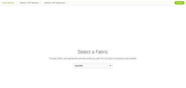
Click Continue. The Select a Fabric screen comes up.
-
Select Easy7200 and click Continue at the top right part of the screen.
The Networks screen comes up.
-
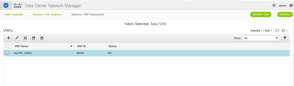
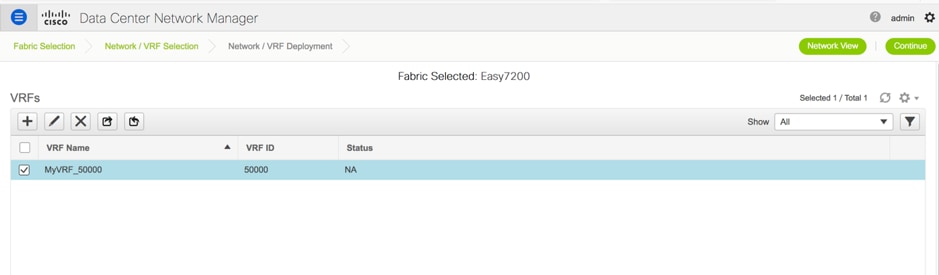
Click VRFs at the top right part of the screen. The VRFs screen comes up.
-
Select the VRF that you want to deploy (MyVRF_5000 in this case) and click Continue at the top right part of the screen.
The Easy7200 fabric topology comes up.
-
Select the Multi-Select checkbox at the top right part of the screen and drag the cursor across the BGWs on which you want to deploy the VRF and
VRF extension configuration.
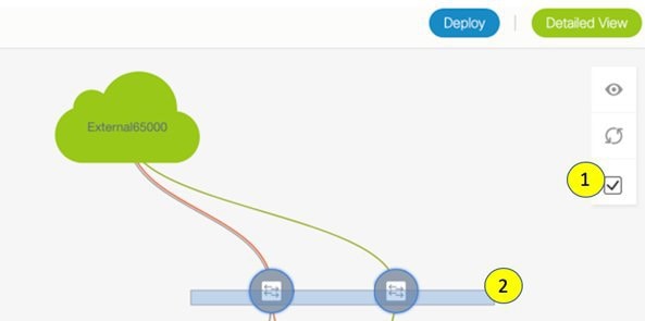
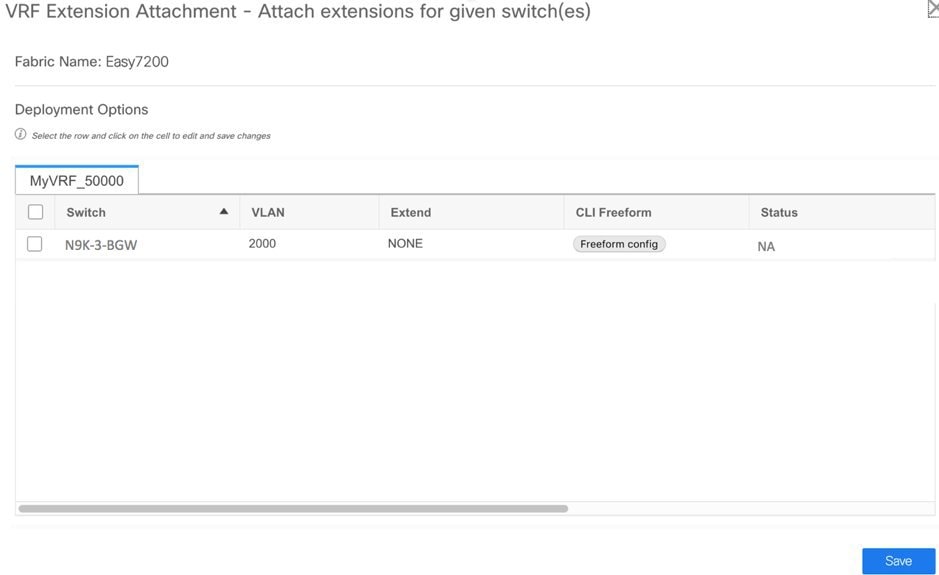
The VRF Extension Attachment screen comes up. Each row represents a switch and each tab a VRF. Update settings for each tab as explained.
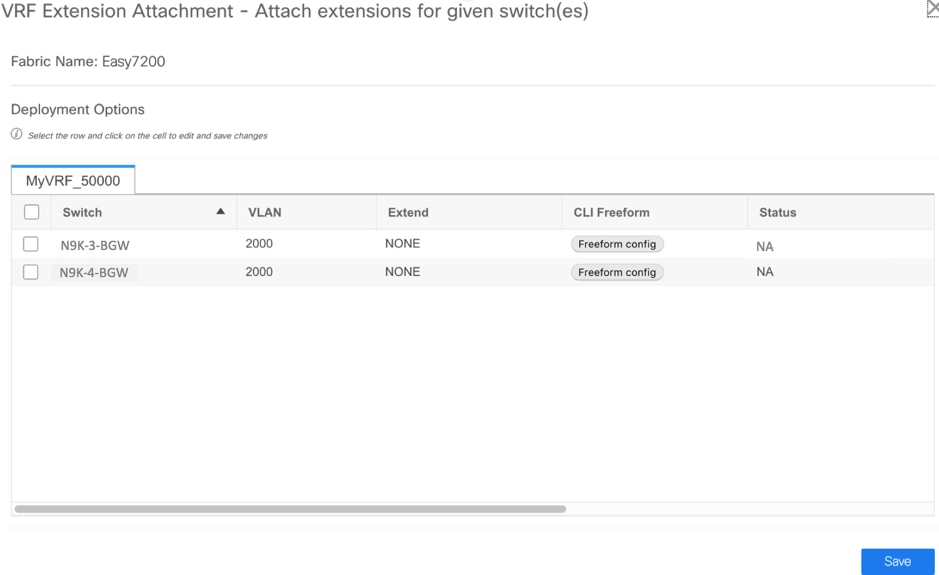
In the Extend column, click on NONE and choose the VRF_LITE option from the drop down box. Do this for the second row too.
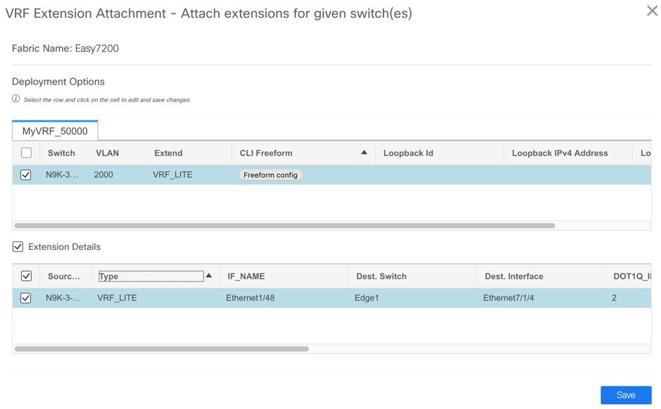
Select the checkboxes in both rows.
The Extension Details section comes up at the bottom of the screen. It displays the IFCs created on the selected switches, wherein each row represents
an IFC.
Select the IFC check boxes in both rows.
After selecting the IFCs, the screen looks like this.

Click Save at the bottom right part of the screen.
The fabric topology screen comes up.
-
Click the Preview option at the top right part of the screen to preview VRF and VRF extension configuration.
-
Click Deploy at the top right part of the screen.
At the bottom right part of the screen, the color codes that represent different stages of deployment are displayed. The color
of the switch icons changes accordingly (Blue for Pending state, yellow for In Progress state when the provisioning is in
progress, red for failure state, green when successfully deployed).
When the switch icons turn green, it means that the VRFs are successfully deployed.
The second step in the VRF Lite configuration scenario, deploying VRF extensions on the border devices is complete. Next,
the VRF extensions are deployed on the edge router n7k1-Edge1.
Step 1 - Deploy IFC prototypes on physical interfaces, on N9K-3-BGW and N9K-4-BGW.
Step 2 - Deploy the individual VRF extensions on the BGWs N9K-3-BGW and N9K-4-BGW.
Step 3 - Deploy VRF extensions on the edge router n7k1-Edge1.
The third step completes the configuration between Easy7200 and External65000.
Step 3
- Deploy VRF extensions on the edge router n7k1-Edge1
In order to extend VRFs on the edge router, keep a note of the following fields. VRF extension on the border device is on
a per interface basis.
-
IP_MASK - This will become the neighbor address at the edge router end and mask will be the local mask on the edge router. This is
derived from the IFC prototype created in the earlier step.
-
Easy Fabric ASN - This will become neighbor ASN from the edge router end. This is derived from the IFC prototype created in the earlier step.
-
Dot1Q tag - This will be same on the edge router. This is derived from the VRF extension table.
-
Neighbor ASN - This will become LOCAL ASN on the edge router. IFC prototype.
-
Neighbor IP - This will become Local IP for sub-interface on the edge router. IFC prototype.
-
Destination port - Will be local port on edge router upon which extension will be deployed.
You have deployed VRF extensions for MyVRF_50000 from the BGWs N9K-3-BGW and N9K-4-BGW. Now, you should deploy the VRF extensions on the other end of the links, on n7k1-Edge1. In DCNM, the CLI template used for this is External_VRF_Lite_eBGP.
eBGP configuration on the edge router
-
In the External65000 fabric topology screen, click Tabular view.
The Switches | Links screen comes up.
-
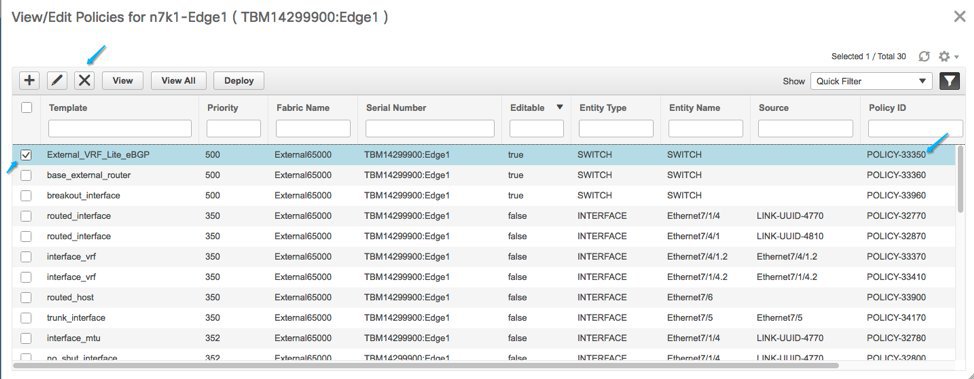
Select the switch checkbox and click the View/Edit Policies button.
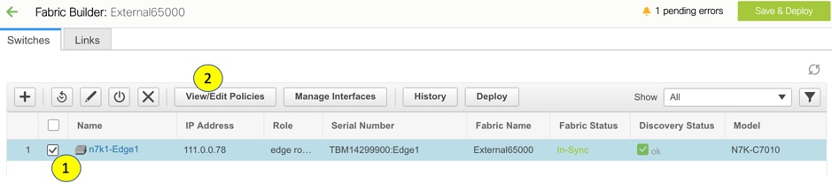
The View/Edit Policies screen comes up.
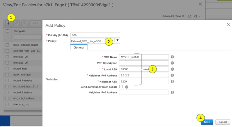
-
Click + at the top left part of the screen to add a policy, and fill in the Add Policy screen as shown in the image.
You can use a user defined template too in the Policy field.
Note |
Note the policy ID for this VRF extension. It is useful when deleting the policy to remove the extension, when applicable.
|
This defines a policy from the edge router towards N9K-3-BGW.
-
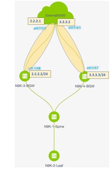
As per the earlier steps, create a policy for the VRF extension towards N9K-4-BGW. The Neighbor IPv4 Address field for the second extension is updated with 3.3.3.3.
Sub interface policy on Edge Router
-
In the External65000 fabric topology screen, click Tabular view.
The Switches | Links screen comes up.
-
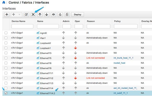
Select the switch checkbox and click the Manage Interfaces button.
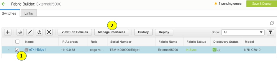
The Manage Interfaces screen comes up.
-
As shown in the image, select the interface connected to the border device (in this case Eth7/1/4), and click + at the top left part of the screen. Then, fill the Add Interface screen from corresponding IFC and VRF extensions on the border device.
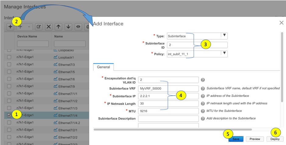
The example shows a break out port on the Cisco Nexus 7000 Series switch. This breakout must be performed using the DCNM breakout
policy (the template name is breakout_interface). If this is not done, the subinterface deletion is blocked by DCNM.
-
Click Save to save the settings, and Deploy to deploy the settings onto the switch.
-
As explained in the earlier steps, create another subinterface policy for the VRF extension towards N9K-4-BGW. The Subinterface IP field for the second extension is updated with 3.3.3.1.
The third step in the VRF Lite configuration scenario, deploying VRF extensions on the edge router N7k1-Edge1 is complete. This step completes the configuration between Easy7200 and External65000.
 Feedback