About ITD
Intelligent Traffic Director (ITD) is an intelligent, hardware-based, multi-terabit solution that allows you to build a scalable architecture for Layer 3 and Layer 4 traffic distribution, load balancing, and redirection.
Benefits of ITD:
-
Multi-terabit solution at line rate
-
Transparency to end device and stateless protocol benefits
-
Reduced complexities and architecture scaling for alternative features like Web Cache Communication Protocol (WCCP) and policy-based routing
-
Simplified provisioning and ease of deployment
-
Legacy service appliances can co-exist with new ones
-
Removes the requirement for an expensive external load balancer
-
No certification, integration, or qualification needed between the devices and the Cisco NX-OS switch
-
Order of magnitude OPEX savings : reduction in configuration, and ease of deployment
-
CAPEX savings : No service module or external L3/L4 load-balancer needed. Every Nexus port can be used as load-balancer
ITD features:
-
Hardware based multi-terabit/s L3/L4 load-balancing at wire-speed
-
Zero latency load-balancing
-
Redirect line-rate traffic to any devices, for example web cache engines, Web Accelerator Engines (WAE), video-caches, etc
-
Capability to create clusters of devices, for example, Firewalls, Intrusion Prevention System (IPS), or Web Application Firewall (WAF), Hadoop cluster
-
IP-stickiness
-
Resilient (like resilient ECMP), Consistent hash
-
Virtual IP based L4 load-balancing
-
Weighted load-balancing and Failaction are supported among nodes
-
Load-balances to large number of devices/servers
-
ACL along with redirection and load balancing simultaneously
-
Bi-directional flow-coherency. Traffic from A–>B and B–>A goes to same node
-
The servers/appliances don’t have to be directly connected to Nexus switch
-
Monitoring the health of servers/appliances with IP SLA-based probes
-
N + M redundancy (N number of nodes and M number of hot-standbys)
-
Automatic failure handling of servers/appliances
-
VRF support, vPC support
-
Supports both IPv4 and IPv6 (all platforms do not support IPv6)
-
The feature does not add any load to the supervisor CPU
-
Handles unlimited number of flows
-
Nondisruptive node addition or deletion
-
Simultaneous redirection and load balancing
-
Rate sharing across multiple ITD services in the same switch
Use case examples:
-
Load-balance to cluster of Firewalls.
-
Scale IPS, IDS and WAF by load-balancing to NX-OS devices
-
Scale the NFV solution by load-balancing to low cost VM/container based NFV
-
Scale the WAAS / WAE solution. Traffic redirection mechanism for the Wide Area Application Services (WAAS) or Web Accelerator Engine (WAE) solution
-
Scale the VDS-TC (video-caching) solution
-
Scale Layer-7 load-balancers, by distributing traffic to L7 LBs
-
Replaces ECMP or the port channel to avoid rehashing . ITD is resilient, and doesn’t cause re-hashing on node add/delete/failure
-
Server load balancing in DSR (Direct Server Return) mode
-
Scales up NG intrusion prevention systems (IPSs) and web application firewalls (WAFs) by load balancing to NX-OS devices
-
Load balances to Layer 5 through Layer 7 load balancers
Deployment Modes
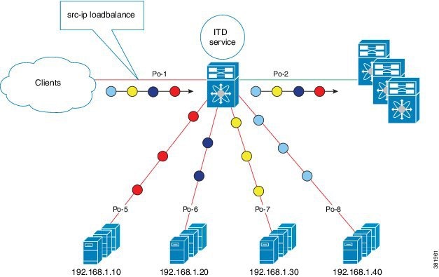
One-Arm Deployment Mode
You can connect servers to the switch in one-arm deployment mode. In this topology, the server is not in the direct path of client or server traffic, which enables you to plug a server into the network with no changes to the existing topology or network.
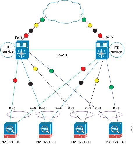
One-Arm Deployment Mode with vPC
ITD supports an appliance pool connected to a virtual port channel (vPC). The ITD service runs on each switch, and ITD programs each switch to provide flow-coherent traffic passing through the nodes.
 Note |
It is recommended to use failaction bucket distribute for VPC scenarios (not using ITD NAT) to keep consistent behavior across peers on failures of nodes reachable over VPC. |
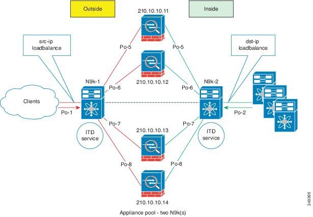
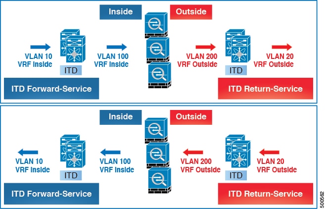
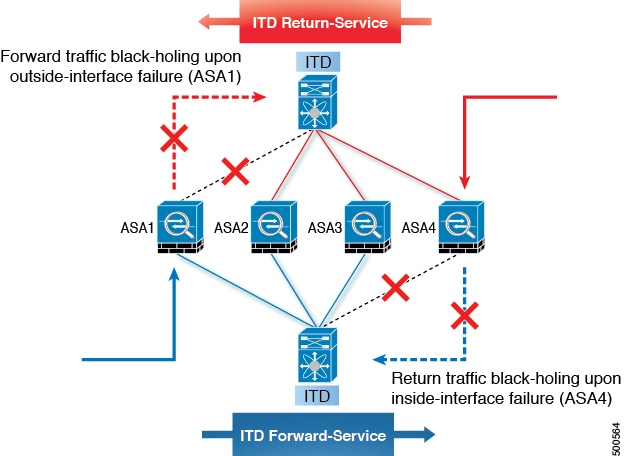
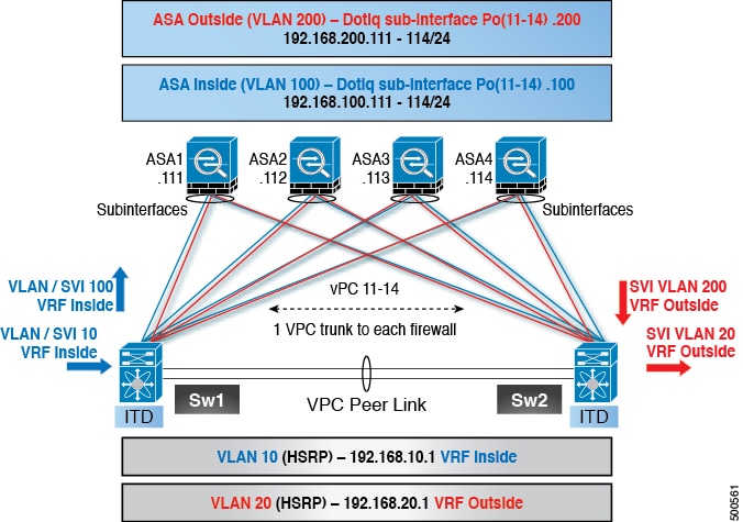
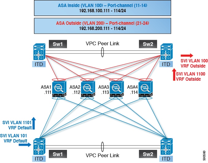
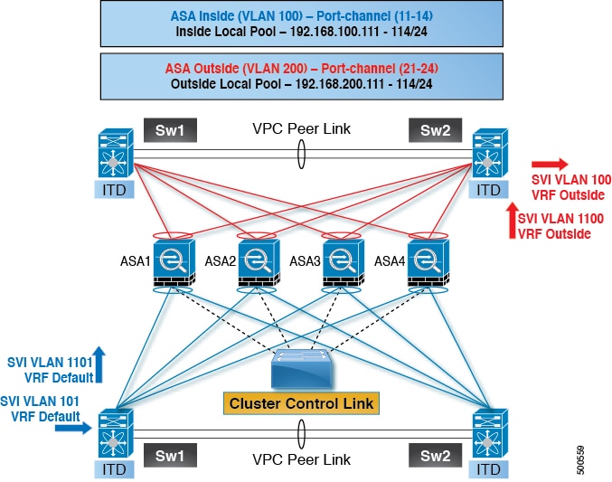
Sandwich Deployment Mode
The sandwich deployment mode uses two switches to provide stateful handling of traffic.
The main requirement in this mode is that both the forward and reverse traffic of a flow must go through the same appliance. Examples include firewalls and load balancer deployments, where traffic between the client and the server must flow through the same appliance.
The key features are:
-
An ITD service for each network segment, one for the outside network and another for the inside network.
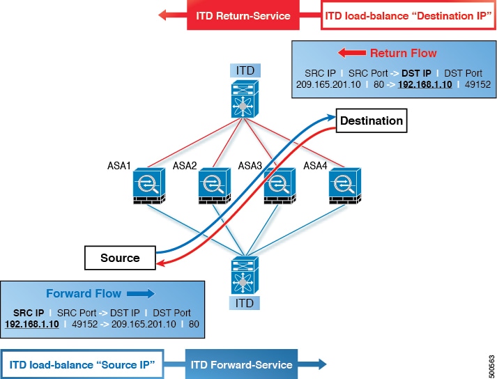
-
A source IP address load-balancing scheme where the ITD service operates on the interface that connects to the outside world in an ingress direction.
-
A destination IP address load-balancing scheme where the ITD service operates on the interface that connects to the servers in the ingress direction.
-
If a user-defined access-list (include ACL) is used in the ITD service in the outside network, an access-list with reversed ACE rules should be created and applied as a user ACL in the ITD service in the inside network.
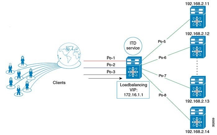
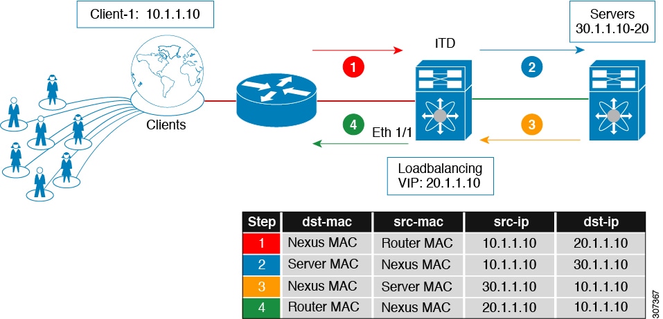
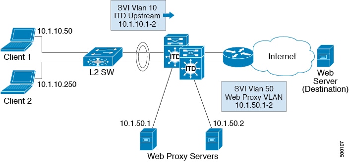
Server Load-Balancing Deployment Mode
The ITD service can be configured to host a virtual IP (VIP) on the switch. Internet traffic destined for the VIP will be load balanced to the active nodes. The ITD service is not a stateful load balancer.
Note |
You need to configure the ITD service manually and in a similar manner on each switch. |
Destination NAT
Network Address Translation (NAT) is a commonly deployed feature in load balancing, firewall, and service appliances. Destination NAT is one of the types of NAT that is used in load balancing.
Benefits of Destination NAT
The following are the benefits of using NAT in ITD deployments:
-
Not all the servers in the server pool are required to host the virtual IP address, as in DSR (Direct Server Return) mode of deployment.
-
The client, which is not required to be aware of the Server IP, always sends the traffic to the virtual IP address.
-
The load balancer detects server failures, and redirects the traffic to the appropriate server, without the client being aware of the status of the primary server.
-
NAT provides security by hiding the real server IP from the client.
-
NAT provides increased flexibility in moving the real servers across different server pools.
Among the different types of NAT, Destination NAT is deployed commonly in load balancing because of the following advantages it provides:
-
The traffic from source or client to the virtual IP address is rewritten and redirected to server.
-
The traffic from the source or client to the destination or server, which is the forward path, is handled as follows: the traffic from the source or client to virtual IP address is translated and redirected as the traffic from source to the destination or server.
-
The traffic from the destination to the source or client, which is the reverse path, is re-translated with the virtual IP address as the source IP address.
The following figure illustrates the NAT with Virtual IP Address:
Port Address Translation (PAT)
PAT translates multiple real addresses to a single mapped IP address by translating the real address and source port to the mapped address and a unique port. If available, the real source port number is used for the mapped port. However, if the real port is not available, by default the mapped ports are chosen from the same range of ports as the real port number: 0 to 511, 512 to 1023, and 1024 to 65535. PAT lets you use a single mapped address, thus conserving routable addresses.
ITD Over VXLAN
ITD which used to be a single switch solution will now work as a load-balancer in a VxLAN fabric.
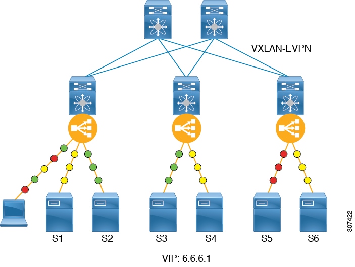
In a programmable fabric, the servers, the virtual machines (VMs), and the containers (specific to a given service) can be distributed across the fabric, and attached to different ToR or leaf switches. The ITD Over VXLAN feature enables load balancing to the servers that are distributed across the fabric.
ITD Over VXLAN enables fabric to act as a massive load-balancer and makes it capable of providing massive telemetry and analytics. When ITD Over VXLAN is used as a load-balancer, you can connect between Layer 4 and Layer 7 appliances anywhere in the fabric. This is shown in figure, Load Balancing across the Fabric.
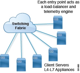
You may have a large number of clients (local and across the border leaf), that include database servers, application servers, web servers, firewalls, WAAS, IPS, IDS, and video caches. The information about traffic flowing to each firewall, WAAS, IPS, IDS, and server from each device in the fabric, including information about when traffic is high or low is very valuable.
ITD Over VXLAN sits on the path between clients and servers or Layer 4 and Layer 7 services, making it aware about traffic information. With this information it provides valuable traffic analytics and telemetry.
In the load balancing function, a virtual IP (VIP) abstracts a service provided by a physical server farm distributed across the DC fabric. When different clients (local to fabric or from a remote location) send requests for a given service, these requests are always destined to the VIP of these servers.
On the ToR or leaf switches, ITD matches the source IP address bits and mask, the destination IP address (Virtual IP address), and relevant Layer 3 or Layer 4 fields to load balance these requests among the servers.
ITD Over VXLAN provides an infrastructure to configure a cluster of the servers (nodes) inside a device group. It segregates the client traffic based on the buckets (bit mask), and the tenant SVI configured under the ITD service. Based on the defined cluster of nodes (servers) and buckets, ITD automatically creates rules to match the client IP traffic into the buckets mask and redirects the matched traffic to a specific server node.
In case, if server become non-responsive or non-operational then ITD automatically switches the client traffic from the non-operational node to a single or group of configured standby nodes. Traffic assignment is achieved by automatically changing flows to a standby node.
ITD Over VXLAN currently uses Direct Server Return (DSR) concept and functionality so that server responses are directly sent to the client. It is fabric agnostic but currently supported with VXLAN EVPN Fabric and is currently supported on Cisco Nexus 9000 Series switches that support PBR over VXLAN.
ITD Over VXLAN is achieved at line-rate speed.
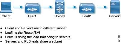
High-level Overview of Configuring ITD Over VXLAN Topology
A high-level overview of configuring ITD Over VXLAN on the ToR switch is as follows:
-
Identify load balancing servers and create a device group.
-
Create an ITD service instance for the group, and complete the following:
-
Associate a virtual IP address (VIP) for incoming ITD Over VXLAN traffic. The VIP represents the servers in the device group.
-
Enable other load balancing configuration.
-
Configure the interfaces where the service needs to be activated as the ingress interface of the service. Enable the ITD service.
-
Apply the identical ITD configuration on every leaf switch where the servers (ITD nodes) are connected. Configure the L3 VNI as the ingress interface of this service on these leaf switches. Enable the ITD service.
-
Benefits of ITD over VXLAN
-
Load balancing of servers/VMs/Containers distributed anywhere in the fabric
-
Not hardware dependent
-
Health monitoring of nodes in data plane for directly attached nodes and probe summarization.
-
Analytics and telemetry provide details about when/how to grow capacity of servers (i.e., spawn VM/containers) and appliances (elastic data center).
-
Builds an Elastic Data Center.
-
Load-balance across VXLAN Network Identifier (VNI) interfaces.
-
Synchronization of load balancing across multiple switches in fabric.
-
Auto-synchronization of failure information.
-
Recommendation system.
-
Works in VXLAN-EVPN fabrics with all possible datacenter topologies.
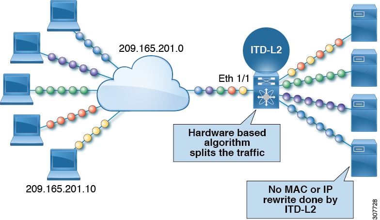
About Layer-2 load balancing
Layer-2 (ITD-L2) load balancing is a hardware-based, multi-terabit solution for the Layer 2 traffic distribution, load balancing, and redirection on the Cisco Nexus switches.
Note |
ITD-L2 feature is not supported on Cisco 9500 EX / FX line cards. |
ITD-L2 is an aggregation of multiple physical links that creates a single logical link. You can bundle up multiple physical links into a port group to provide an increased bandwidth (an aggregate of the multiple physical links) and redundancy.
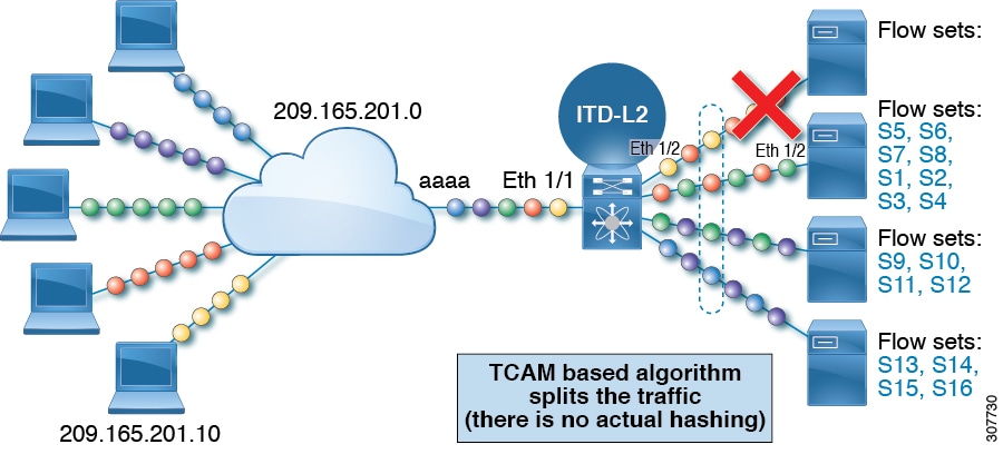
If one port within the Layer-2 fails, the traffic switches to the remaining ports in the Layer-2
ITD-L2 allows you to create a cluster of transparent mode appliances.
Layer-2 load balancing Features
The ITD-L2 features are as follows:
-
Multi-terabit solution at line rate
-
Simplified provisioning and ease of deployment
-
Transparency to end device and stateless protocol benefits
-
Removes the requirement for an expensive external load balancer
Benefits of ITD Layer -2 load balancing
The benefits of ITD Layer -2 load balancing are as follows:
-
Simultaneous redirection and load balancing
-
IP-stickiness and resiliency
-
Health monitoring of ports
-
Removes the requirement for an expensive external load balancer
-
Hashing does not depend on the wiring or the port numbering
-
Every port on the switch is used for load balancing and traffic redirection
Examples of the Deployment Use Cases
Examples of the deployment use cases for the ITD-L2 feature are as follows:
-
Load balances to a pool of firewalls.
-
Scales the VDS-TC (video-caching) solution.
-
Scales the transparent mode devices.
Topology Examples for ITD-L2
This section displays the following examples:
-
Basic topology for ITD-L2
-
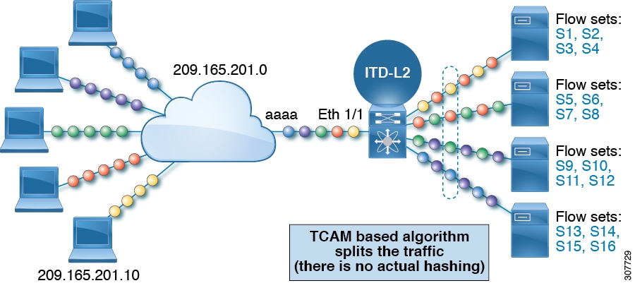
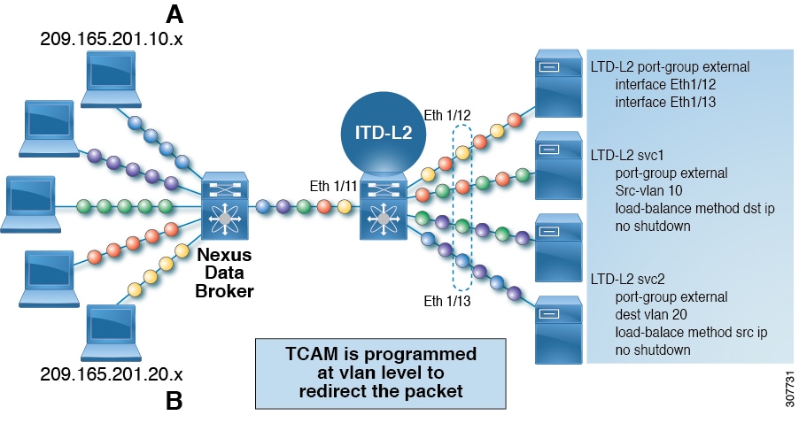
Use case of a ITD-L2 configuration
-
Fail-action for resilient hashing
Prerequisites for Layer-2 load balancing
Layer-2 load balancing has the following prerequisite:
-
You must ensure that an enough TCAM size has been allocated to the VACL. To verify the TCAM size, use the sh hardware access-list tcam region command. If the appropriate TCAM size is not allocated, use the hardware access-list tcam region VACL <size multiple of 256> command to allocate the appropriate TCAM size.
Device Groups
Nodes can be a physical server, virtual server, or a service appliance where traffic can be load balanced. These nodes are grouped together under a device group, and this device group can be mapped to a service.
ITD supports device groups. When you configure a device group, you can specify the following:
-
The device group's nodes
-
The device group's probe
You can configure probes at the device-group level or at the node level. With node-level probing, each node can be configured with its own probe, allowing for further customization per node. Node-level probes are useful in scenarios where each node needs to be monitored differently for failure conditions.
Multiple Device Groups in an ITD Service
device groups are supported in an ITD service (as shown in the figure below). An ITD service generates a single route map with different sequences that point to different device groups.
Each device group represents different types of traffic requiring different services but arriving on the same ingress interface. Traffic on the interface is redirected to the appropriate device group based on the virtual IP address. Supporting multiple device groups per ITD service on the same interface allows ITD to scale.

For a configuration example showing how to configure multiple device groups in an ITD service, see .
VRF Support
The ITD service can be configured in the default VRF as well as in non-default VRFs.
Ingress interfaces and device-group nodes must all belong to the same VRF for the ITD service to redirect traffic. You must ensure that all ingress interfaces and node members of the associated device group are reachable in the configured VRF.
Router ACLs
The switch supports router access control lists (RACLs) with ITD.
You can configure ITD and an RACL on the same ingress interface. The resulting RACL, which is downloaded to the TCAM, is a cross product of the ACL generated by ITD and the user-configured RACL. The permit and deny statements configured on the RACL are combined with the ACL permits and redirect entries created by ITD. This functionality helps you to filter and load distribute selected traffic.
Note |
|
Include and Exclude ACLs
Include ACL
The include ACL feature allows you to assign an access control list (ACL) to an ITD service. Only traffic matching the ACE is load-balanced toward the nodes and other traffic follows default routing rules.
Beginning from Cisco NX-OS Release 9.3 (3), you can configure up to 8 access-lists under one ITD service. You can associate each access list with its own device-group (Multi-ACL). When specific device-group is associated with one user ACL, that device-group takes priority and overwrites the default device-group. With this feature, ITD can load-balance traffic matching different ACLs to different device-groups.
Exclude ACL
You can configure an exclude ACL to specify the traffic that you want ITD to exclude from the ITD load balancer. The traffic, which the exclude ACL selects, is RIB-routed and bypasses ITD. An exclude ACL can filter based on both source and destination fields. The exclude ACL precedes the virtual IP address.
Virtual IP Address Filtering
A virtual IP address can be used to filter traffic for ITD. A virtual IP address and subnet mask combination for traffic filtering is supported for the destination field only.
Port Number-Based Filtering
Port numbering can be used to filter traffic for ITD. The following methods are supported to filter traffic based on Layer 4 ports (for example, port 80):
-
Matching destination ports
Any source or destination IP address with destination port 80 is matched. (For example: The virtual IP address is configured as 0.0.0.0 0.0.0.0 tcp 80.)
-
Matching source ports
Any port other than 80 bypasses ITD, and port 80 is redirected. (For example: The exclude ACL is configured as permit tcp any neq 80 any.)
-
Matching multiple port numbers
Multiple virtual IP address lines in ITD can be configured, one for each port.
Hot-Standby
The hot-standby feature reconfigures the switch to look for an operational hot-standby node and select the first available hot-standby node to replace the failed node. ITD reconfigures the switch to redirect the traffic segment that was originally headed toward the failed node to the hot-standby node. The service does not impose any fixed mapping of hot-standby nodes to active nodes.
When the failed node becomes operational again, it is reinstated as an active node. The traffic from the acting hot-standby node is redirected back to the original node, and the hot-standby node reverts to the pool of standby nodes.
When multiple nodes fail, traffic destined to all failed nodes gets redirected to the first available hot-standby node.
The hot-standby node can be configured only at the node level . At the node level, the hot-standby node receives traffic only if its associated active node fails.
ITD supports N + M redundancy where M nodes can act as hot-standby nodes for N active nodes.
Multiple Ingress Interfaces
You can configure the ITD service to apply traffic redirection policies on multiple ingress interfaces. This feature allows you to use a single ITD service to redirect traffic arriving on different interfaces to a group of nodes.
same ingress interface can be included in two ITD services, allowing one IPv4 ITD service and one IPv6 ITD service.
Including the same ingress interface in both IPv4 and IPv6 ITD services allows both IPv4 and IPv6 traffic to arrive on the same ingress interface. An IPv4 ITD policy is applied to redirect the IPv4 traffic, and an IPv6 ITD policy is applied to redirect the IPv6 traffic.
Note |
Make sure that the same ingress interface is not referenced in more than one IPv4 ITD service or more than one IPv6 ITD service. The system does not automatically enforce it and it is not supported. |
System Health Monitoring
ITD monitors health of the nodes and applications running on those nodes periodically to detect any failures and to handle the failure scenarios.
ICMP, TCP, UDP probes are supported.
Health of an Interface Connected to a Node
leverages the IP service level agreement (IP SLA) feature to periodically probe each node. ITD uses the Internet Control Message Protocol (ICMP) to periodically probe each node. The probes are sent at a 10-second frequency by default and can be configured down to 1 second. They are sent simultaneously to all nodes. You can configure the probe as part of the pool group configuration.
A probe is declared to have failed after retrying three times by default. At this point, the node state becomes “Failed,” and its status becomes “PROBE_FAILED.”
Node Failure Handling
Upon marking a node as down, the ITD performs the following tasks automatically to minimize traffic disruption and to redistribute the traffic to remaining operational nodes:
-
Determines if a standby node is configured to take over from the failed node.
-
If the standby node is operational, it is identified the node as a candidate node for traffic handling.
-
Redefines the standby node as active for traffic handling, if an operational standby node is available
-
Programs automatically to reassign traffic from the failed node to the newly active standby node.
User-defined track ID for Probes
Users can define their own tracks and associate them with each node. If a node is assigned a user-defined track, corresponding ip sla configuration needs to be configured by the user to work with the track. ITD will not allocate new track and ip sla ID for the node. User-defined track can be assigned to primary, standby and hot-standby nodes. User can assign a user-defined track to a new node that has been added by ITD session.Tracks generated by ITD cannot be used as a use-defined track.
Example for Adding a new node with user-defined track:
itd device-group dg1
  node ip 1.1.1.2
    probe track 30
  node ip 1.1.1.3
    probe track 40
  node ip 1.1.1.4
    mode hot-standby
    probe track 50

itd device-group dg2
  node ip 1.1.1.6
    probe track 70
    standby ip 1.1.1.5
      probe track 60
If a node doesn’t have a user defined track, ITD service will allocate track id and ip sla ID when a service is enabled.
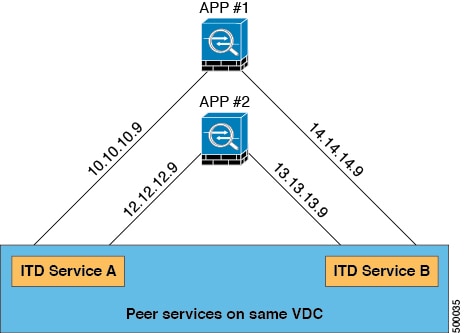
Peer Synchronization
The peer synchronization feature synchronizes the node health status across two ITD peer services in sandwich mode. It is useful in preventing traffic loss if a link on one of the ITD peer services goes down.
Each ITD service probes its peer service periodically to detect any failure. A ping is sent every second to the ITD peer service. If a reply is not received, it is retried three times. The frequency and retry count are not configurable.
Note |
Peer-service feature requires fail-action least-bucket or fail-action node per-bucket to be configured, to allow for synchronized fail-over of nodes across services. Additionally synchronized fail-over is not supported when either service is using hot-standby nodes or node level standbys. |
Failaction Reassignment
Failaction for ITD enables traffic to the failed nodes to be reassigned to one or more active nodes. When the failed node becomes active again, it resumes serving connections. If all the nodes are down, the packets are routed automatically. All Failaction mechanisms are supported for both IPv4 and IPv6 services.
Note |
You must configure a probe under an ITD device group before enabling the failaction feature. |
Failaction Node Reassign
When a node goes down, the traffic buckets associated with the node are reassigned to the first active node found in the configured set of nodes. If the newly reassigned node also fails, traffic is reassigned to the next available active node.
When a node recovers and in the lack of any further failure events, the traffic buckets originally assigned to the node before any failures, are reassigned to it.
Failaction Node Least-Bucket
When a node goes down, the traffic buckets associated with the node are reassigned to an active node that is currently receiving traffic from the least number of traffic buckets. For each subsequent node failure, the active node with least traffic buckets is recomputed and all the buckets directed to a failed node are redirected to this node, thereby allowing the re-assigned buckets to be distributed over multiple active nodes.
When a node recovers and in the lack of any further failure events, the traffic buckets originally assigned to the node before any failures, are reassigned to it.
Failaction Bucket Distribute
When the service is enabled, ITD uses an internal algorithm to preselect varied sequences of primary nodes as alternate backup paths for with different priorities for each primary node. When a node goes down, the traffic to the node will be re-directed to the first active backup node with the highest priority, and so on, for subsequent failures, thereby minimizing the convergence delays.
When a node recovers, the traffic buckets originally assigned to this node as the primary will be reassigned to it. Any traffic buckets whose primary node is still in failure, for which the newly recovered node behaves as the highest priority active backup will also be re-assigned to it.
the primary nodes of a device-group or up to 32 primary nodes of a device-group (whichever is lesser) shall be preselected with different priorities for each node.
Note |
This algorithm is intended for relatively even traffic distribution but doesn't guarantee even distribution with node failures. |
Failaction Optimization
Prior to Cisco NX-OS Release 9.2 (2), when the node goes down, the buckets associated with the node are reassigned to an active node as determined by the fail-action algorithm. However if the newly reassigned node has also failed simultaneously, the traffic buckets for the original failed node have to be re-assigned to another active node, after re-running the fail-action computation. The delay in reassigning the failed node buckets to an active node impacts the network performance.
With fail-action optimization, when a node goes down, the status of all available nodes is first proactively fetched. The re-assignment of all nodes detected as failed will then be done based on the fail-action mechanism, thereby avoiding the delays in repeated re-assignment.
Beginning from Cisco NX-OS Release 9.3 (3), this optimization is enabled by default for all services , except when peer-synchronization is configured.
Failaction Node-Per-Bucket
When a particular node fails, the node with least number of buckets are identified and the buckets are distributed across the other active nodes, starting from the node with least buckets.
ITD repeatedly identifies the least buckets node currently and assign one bucket to the node until all buckets are reassigned. Hence all buckets are distributed evenly among all remaining active nodes.
Note |
identifies the nodes to fail-over, based on the weights of the nodes. If a node doesn't have a weight configured a default weight of 1 is used. |
No Failaction Reassignment
When failaction node reassignment is not configured, there are two possible scenarios:
No Failaction Reassignment with a Probe Configured
The ITD probe can detect the node failure or the lack of service reachability. If the node fails, the traffic is routed and does not get reassigned, as failaction is not configured. Once the node recovers, the recovered node starts to handle the traffic.
No Failaction Reassignment without a Probe Configured
Without a probe configuration, ITD cannot detect the node failure. When the node is down, ITD does not reassign or redirect the traffic to an active node.
 Feedback