Configuring Q-in-Q VLAN Tunnels

Q-in-Q Tunnels

This chapter describes how to configure IEEE 802.1Q-in-Q VLAN tunnels and Layer 2 protocol tunneling on Cisco NX-OS devices.

A Q-in-Q VLAN tunnel enables a service provider to segregate the traffic of different customers in their infrastructure, while still giving the customer a full range of VLANs for their internal use by adding a second 802.1Q tag to an already tagged frame.

Q-in-Q Tunneling

Business customers of service providers often have specific requirements for VLAN IDs and the number of VLANs to be supported. The VLAN ranges required by different customers in the same service-provider network might overlap, and the traffic of customers through the infrastructure might be mixed. Assigning a unique range of VLAN IDs to each customer would restrict customer configurations and could easily exceed the VLAN limit of 4096 of the 802.1Q specification.

  • Using the 802.1Q tunneling feature, service providers can use a single VLAN to support customers who have multiple VLANs. Customer VLAN IDs are preserved and the traffic from different customers is segregated within the service-provider infrastructure even when they appear to be on the same VLAN.

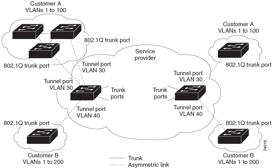
  • The 802.1Q tunneling expands the VLAN space by using a VLAN-in-VLAN hierarchy and tagging the tagged packets. A port configured to support 802.1Q tunneling is called a tunnel port. When you configure tunneling, you assign a tunnel port to a VLAN that is dedicated to tunneling. Each customer requires a separate VLAN, but that VLAN supports all of the customer’s VLANs.

  • Customer traffic that is tagged in the normal way with appropriate VLAN IDs comes from an 802.1Q trunk port on the customer device and into a tunnel port on the service-provider edge switch. The link between the customer device and the edge switch is an asymmetric link because one end is configured as an 802.1Q trunk port and the other end is configured as a tunnel port. You assign the tunnel port interface to an access VLAN ID that is unique to each customer.

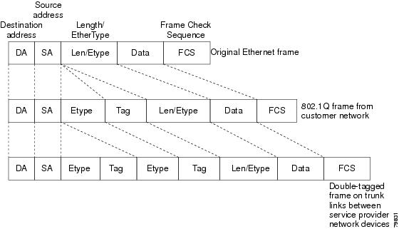
  • Packets that enter the tunnel port on the service-provider edge switch, which are already 802.1Q-tagged with the appropriate VLAN IDs, are encapsulated with another layer of an 802.1Q tag that contains a VLAN ID that is unique to the customer. The original 802.1Q tag from the customer is preserved in the encapsulated packet. Therefore, packets that enter the service-provider infrastructure are double-tagged.

  • The outer tag contains the customer’s access VLAN ID (as assigned by the service provider), and the inner VLAN ID is the VLAN of the incoming traffic (as assigned by the customer). This double tagging is called tag stacking, Double-Q, or Q-in-Q.

  • By using this method, the VLAN ID space of the outer tag is independent of the VLAN ID space of the inner tag. A single outer VLAN ID can represent the entire VLAN ID space for an individual customer. This technique allows the customer’s Layer 2 network to extend across the service provider network, potentially creating a virtual LAN infrastructure over multiple sites.


Note


Q-in-Q is supported on port channels. To configure a port channel as an asymmetrical link, all ports in the port channel must have the same tunneling configuration.


Figure 1. 802.1Q-in-Q Tunnel Ports


Figure 2. Untagged, 802.1Q-Tagged, and Double-Tagged Ethernet Frames


Note


Hierarchical tagging, or multi-level dot1q tagging Q-in-Q, is not supported.


Native VLAN Hazards

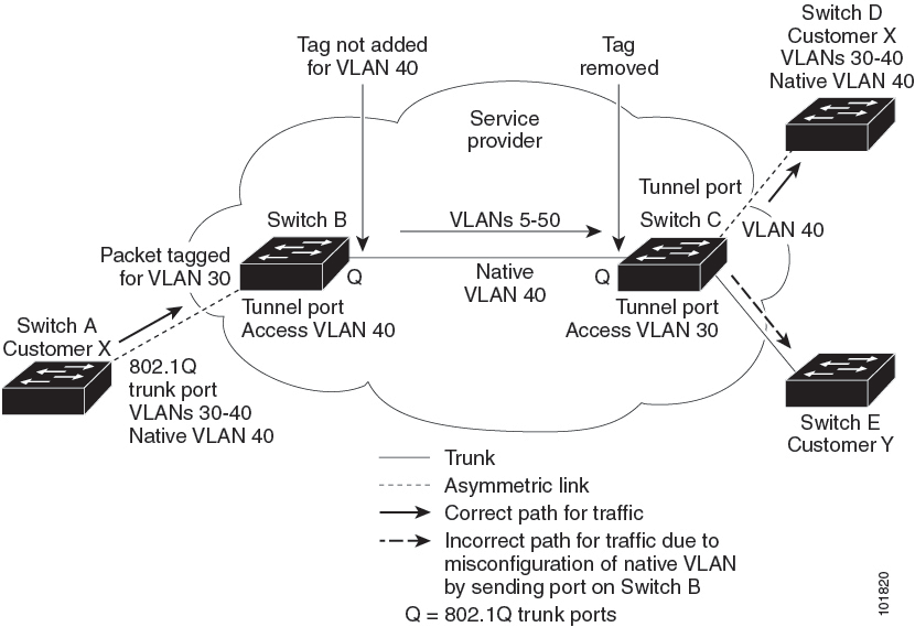
When configuring 802.1Q tunneling on an edge switch, you must use 802.1Q trunk ports for sending out packets into the service-provider network. However, packets that go through the core of the service-provider network might be carried through 802.1Q trunks, ISL trunks, or nontrunking links. When 802.1Q trunks are used in these core switches, the native VLANs of the 802.1Q trunks must not match any native VLAN of the dot1q-tunnel port on the same switch because traffic on the native VLAN is not tagged on the 802.1Q transmitting trunk port.

In the figure below, VLAN 40 is configured as the native VLAN for the 802.1Q trunk port from Customer X at the ingress edge switch in the service-provider network (Switch B). Switch A of Customer X sends a tagged packet on VLAN 30 to the ingress tunnel port of Switch B in the service-provider network that belongs to access VLAN 40. Because the access VLAN of the tunnel port (VLAN 40) is the same as the native VLAN of the edge-switch trunk port (VLAN 40), the 802.1Q tag is not added to tagged packets that are received from the tunnel port. The packet carries only the VLAN 30 tag through the service-provider network to the trunk port of the egress-edge switch (Switch C) and is misdirected through the egress switch tunnel port to Customer Y.

These are a couple ways to solve the native VLAN problem:

  • Configure the edge switch so that all packets going out an 802.1Q trunk, including the native VLAN, are tagged by using the vlan dot1q tag native command. If the switch is configured to tag native VLAN packets on all 802.1Q trunks, the switch accepts untagged packets but sends only tagged packets.


    Note


    The vlan dot1q tag native command is a global command that affects the tagging behavior on all trunk ports.


  • Ensure that the native VLAN ID on the edge switch trunk port is not within the customer VLAN range. For example, if the trunk port carries traffic of VLANs 100 to 200, assign the native VLAN a number outside that range.

Figure 3. Native VLAN Hazard


Layer 2 Protocol Tunneling

Customers at different sites connected across a service-provider network need to run various Layer 2 protocols to scale their topology to include all remote sites, as well as the local sites. The Spanning Tree Protocol (STP) must run properly, and every VLAN should build a proper spanning tree that includes the local site and all remote sites across the service-provider infrastructure. The Cisco Discovery Protocol (CDP) must be able to discover neighboring Cisco devices from local and remote sites, and the VLAN Trunking Protocol (VTP) must provide consistent VLAN configuration throughout all sites in the customer network.

  • You can configure the switch to allow multi-tagged BPDUs on a tunnel port. If you enable the l2protocol tunnel allow-double-tag command, when a multi-tagged customer BPDU enters the tunnel port, the original 802.1Q tags from the customer traffic is preserved and an outer VLAN tag (customer’s access VLAN ID, as assigned by the service-provider) is added in the encapsulated packet. Therefore, BPDU packets that enter the service-provider infrastructure are multi tagged. When the BPDUs leave the service-provider network, the outer tag is removed and the original multi-tagged BPDU is sent to the customer network.

  • Starting with Cisco NX-OS Release 7.0(3)I7(3), you can configure the switch to allow multi-tagged BPDUs on a tunnel port. If you enable the l2protocol tunnel allow-double-tag command, when a multi-tagged customer BPDU enters the tunnel port, the original 802.1Q tags from the customer traffic is preserved and an outer VLAN tag (customer’s access VLAN ID, as assigned by the service-provider) is added in the encapsulated packet. Therefore, BPDU packets that enter the service-provider infrastructure are multi tagged. When the BPDUs leave the service-provider network, the outer tag is removed and the original multi-tagged BPDU is sent to the customer network.

  • When protocol tunneling is enabled, edge switches on the inbound side of the service-provider infrastructure encapsulate Layer 2 protocol packets with a special MAC address and send them across the service-provider network. Core switches in the network do not process these packets, but forward them as normal packets. Bridge protocol data units (BPDUs) for CDP, STP, or VTP cross the service-provider infrastructure and are delivered to customer switches on the outbound side of the service-provider network. Identical packets are received by all customer ports on the same VLANs.

  • If protocol tunneling is not enabled on 802.1Q tunneling ports, remote switches at the receiving end of the service-provider network do not receive the BPDUs and cannot properly run STP, CDP, 802.1X, and VTP. When protocol tunneling is enabled, Layer 2 protocols within each customer’s network are totally separate from those running within the service-provider network. Customer switches on different sites that send traffic through the service-provider network with 802.1Q tunneling achieve complete knowledge of the customer’s VLAN.


Note


Layer 2 protocol tunneling works by tunneling BPDUs in the software. A large number of BPDUs that come into the supervisor will cause the CPU load to go up. You might need to make use of software rate limiters to reduce the load on the supervisor CPU. See Configure Thresholds for Layer 2 Protocol Tunnel Ports.


Figure 4. Layer 2 Protocol Tunneling


Figure 5. Virtual Network Topology Without BPDU Tunneling


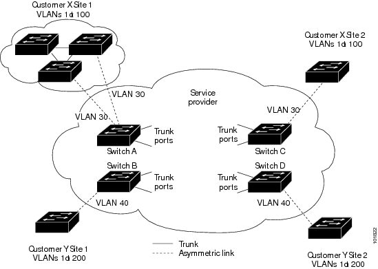
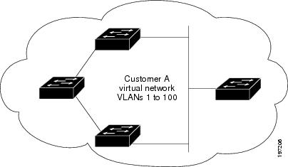
For example, in the figure below, Customer X has four switches in the same VLAN that are connected through the service-provider network. If the network does not tunnel BPDUs, switches on the far ends of the network cannot properly run the STP, CDP, 802.1X, and VTP protocols. In the preceding example, STP for a VLAN on a switch in Customer X, Site 1 will build a spanning tree on the switches at that site without considering convergence parameters based on Customer X’s switch in Site 2. The figure below shows the resulting topology on the customer’s network when BPDU tunneling is not enabled.

Selective Q-in-Qs

Selective Q-in-Q with multiple provider VLANs is a tunneling feature that allows user-specific range of customer VLANs on a port to be associated with one specific provider VLAN and enables you to have multiple customer VLAN to provider VLAN mappings on a port. Packets that come in with a VLAN tag that matches any of the configured customer VLANs on the port are tunneled across the fabric using the properties of the service provider VLAN. The encapsulated packet carries the customer VLAN tag as part of the Layer 2 header of the inner packet.

Guidelines and Limitations for Q-in-Q Tunneling and Layer 2 Protocol Tunneling

Follow these configuration guidelines and limitations when deploying Q-in-Q tunnels and Layer 2 tunneling on Cisco Nexus switches.

  • Q-in-Q should be configured on the customer-facing interface of the service provider’s edge device. If an Ethernet frame ingresses a Cisco Nexus 9000 series switch, the switch cannot encapsulate the frame with two 802.1Q headers within a single forwarding decision. Similarly, if a Q-in-Q-encapsulated Ethernet frame needs to egress a Cisco Nexus 9000 series switch without any 802.1Q headers, the switch cannot decapsulate two 802.1Q headers from the Ethernet frame within a single forwarding decision.

  • Mapping multiple VLANs is supported.

  • Multiple selective Q-in-Q tags are not supported. That is, Q-in-Q does not support multiple SP tags on a single interface.

  • Switches in the service-provider network must be configured to handle the increase in MTU size due to Q-in-Q tagging.

  • MAC address learning for Q-in-Q tagged packets is based on the outer VLAN (Service Provider VLAN) tag. Packet forwarding issues might occur in deployments where a single MAC address is used across multiple inner (customer) VLANs.

  • Layer 3 and higher parameters cannot be identified in tunnel traffic (for example, Layer 3 destination and source addresses). Tunneled traffic cannot be routed.

  • The system dot1q-tunnel transit command have the following limitations:

    • This commands is required on Cisco Nexus 9300-EX/FX/FX2/FX3/GX switches and 9500 switches with 9700-EX/FX/GX line cards if the device is configured with Q-in-Q, Selective Q-in-Q or Selective Q-in-Q with multiple provider VLAN features.

    • It is required that you configure the system dot1q-tunnel transit command on ToR or modular devices.

    • It is required that you configure the system dot1q-tunnel transit command on vPC switches or non-vPC switches.

    • Layer 2 frames that exit trunk ports will always be tagged, even with the native VLAN of the port if these commands have been configured.

    • The MPLS, GRE, and IP-in-IP functionalities will not function effectively in conjunction with the Q-in-Q tunneling features if this command is configured on the switch.

  • Cisco Nexus 9000 Series devices can provide only MAC-layer ACL/QoS for tunnel traffic (VLAN IDs and src/dest MAC addresses).

  • You should use MAC address-based frame distribution.

  • Asymmetrical links do not support the Dynamic Trunking Protocol (DTP) because only one port on the link is a trunk. You must configure the 802.1Q trunk port on an asymmetrical link to trunk unconditionally.

  • You cannot configure the 802.1Q tunneling feature on ports that are configured to support private VLANs. Private VLAN are not required in these deployments.

  • You must disable IGMP snooping on the tunnel VLANs.

  • You should enter the vlan dot1Q tag native command to maintain the tagging on the native VLAN and drop untagged traffic. This command prevents native VLAN misconfigurations.

  • You must manually configure the 802.1Q interfaces to be edge ports.

  • IGMP snooping is not supported on the inner VLAN.

  • Q-in-Q is not supported on the uplink ports of Cisco Nexus 9332PQ, 9372PX, 9372TX, and 93120TX switches and Cisco Nexus 9396PX, 9396TX, and 93128TX switches with the N9K-M6PQ or N9K-M12PQ generic expansion module (GEM).

  • Q-in-Q tunnels might be affected by the limitations of the Application Leaf Engine (ALE) uplink ports on Cisco Nexus 9300 and 9500 Series devices: Limitations for ALE Uplink Ports

  • Q-in-Q tagging is not supported.

  • Layer 2 protocol tunneling is not supported on Cisco Nexus 9500 Series switches with Nexus 9600-R line cards.

  • Cisco Nexus 9500 Series switches with N9K-X9636C-R, N9K-X9636Q-R, N9K-X9636C-RX line cards, Q-in-Q is supported only on port or port-channel Layer 2 Access VLAN Edge devices.

  • FEX configuration is not supported on Q-in-Q ports.

  • If the command l2potocol tunnel stp is configured on a tunnel interface, the VLAN that you configure on the service provider must be different from that of the customer network.

Guidelines and Limitations for Selective Q-in-Q with Multiple Provider VLANs

Guidelines and Limitations for Selective Q-in-Q with Multiple Provider VLANs

This section provides important guidelines and limitations for using selective Q-in-Q with multiple provider VLANs.

  • For selective Q-in-Q with multiple provider VLANs, all the existing limitations and guidelines for selective Q-in-Q apply.

  • Beginning with Cisco NX-OS Release 9.3(5), selective Q-in-Q with multiple provider VLANs feature is supported on Cisco Nexus N9K-C9316D-GX, N9K-C93600CD-GX, N9K-C9364C-GX switches.

  • Selective Q-in-Q with multiple provider VLANs feature is supported on Nexus 9300-EX, 9300-FX, 9300-FX2, 9300-FX3 switches.

  • When you enable multiple provider VLANs on a vPC port channel, you must make sure that the configuration is consistent across the vPC peers.

  • We recommended not to allow provider VLANs on a regular trunk.

  • Only allow native VLAN and provider VLANs on the allowed vlan list of a Selective QinQ trunk interface.

  • Selective QinQ trunk VLANs cannot be mixed with regular VLANs on the same Selective QinQ trunk interface.

  • Port to VLAN mappings (for example: switchport vlan mapping 10 20) is not supported on a port that is configured for selective Q-in-Q with multiple provider VLANs.

  • Private VLAN is not supported on a port that is configured for selective Q-in-Q with multiple provider VLANs.

  • Only Layer 2 switching is supported.

  • Routing on provider VLANs is not supported.

  • FEX is not supported for selective Q-in-Q with multiple provider VLANs.

  • Selective Q-in-Q with multiple provider VLANs commands not DME-ized.

  • When VLAN1 is configured as native VLAN with selective Q-in-Q and selective Q-in-Q with multiple provider tag, traffic on the native VLAN gets dropped. Do not configure VLAN1 as native VLAN when the port is configured with the selective Q-in-Q. When VLAN1 is configured as customer VLAN, then the traffic on VLAN1 gets dropped.

Guidelines and Limitations for Combined Access Port Feature Set

This section summarizes the guidelines and limitations for the Combined Access Port Feature set.

Configuring Q-in-Q Tunnels and Layer 2 Protocol Tunneling

Create an 802.1Q Tunnel Port

Before you begin

You must first configure the interface as a switchport.

You create the dot1q-tunnel port using the switchport mode command.


Note


You must set the 802.1Q tunnel port to an edge port with the spanning-tree port type edge command. The provider VLAN membership of the port is changed using the switchport access vlanvlan-id command.

You should disable IGMP snooping on the access VLAN allocated for the dot1q-tunnel port to allow multicast packets to traverse the Q-in-Q tunnel.


For seamless packet forwarding and preservation of all VLAN tags on pure transit boxes in the SP cloud that have no Q-in-Q encapsulation or decapsulation requirement, configure the system-wide system dot1q-tunnel transit command. To remove the configuration, use the no system dot1q-tunnel transit command.

For the supported platforms and limitations of the system dot1q-tunnel transit or system dot1q-tunnel transit vlanprovider_vlan_list command, see Guidelines and Limitations for Q-in-Q Tunneling and Layer 2 Protocol Tunneling section.

Procedure


Step 1

Use the configure terminal command to enter global configuration mode.

Example:

switch# configure terminal

Step 2

Use the interface ethernet slot/port command to specify an interface to configure and enter interface configuration mode.

Example:

switch(config)# interface ethernet slot/port

Step 3

Use the switchport command to set the interface as a Layer 2 switching port.

Example:

switch(config-if)# switchport

Step 4

Configure the 802.1Q tunnel port settings.

  1. Use the switchport mode dot1q-tunnel command to create an 802.1Q tunnel on the port.

    Example:

    switch(config-if)# switchport mode dot1q-tunnel

    The port will go down and reinitialize (port flap) when the interface mode is changed. BPDU filtering is enabled and CDP is disabled on tunnel interfaces.

  2. Use the spanning-tree port type edge command to designate the port as a spanning-tree edge port.

    Example:

    switch(config-if)# spanning-tree port type edge
  3. Use the switchport access vlanvlan-id command to configure the Provider access VLAN value.

    Example:

    switch(config-if)# switchport access vlan vlan-id

Step 5

(Optional) Use the no switchport mode dot1q-tunnel command to disable the 802.1Q tunnel on the port.

Example:

switch(config-if)# no switchport mode dot1q-tunnel

Step 6

Use the exit command to exit configuration mode.

Example:

switch(config-if)# exit

Step 7

(Optional) Use the show dot1q-tunnel [interfaceif-range] command to display all ports that are in dot1q-tunnel mode. Optionally, you can specify an interface or range of interfaces to display.

Example:

switch(config)# show dot1q-tunnel [interface if-range]

Step 8

(Optional) Use the no shutdown command to clear errors on the interfaces and VLANs where policies correspond with hardware policies. This command allows policy programming to continue and the port to come up. If policies do not correspond, the errors are placed in an error-disabled policy state.

Example:

switch(config)# no shutdown

Step 9

(Optional) Use the copy running-config startup-config command to copy the running configuration to the startup configuration.

Example:

switch(config)# copy running-config startup-config

This example shows how to create an 802.1Q tunnel port:


switch# configure terminal
switch(config)# interface ethernet 7/1
switch(config-if)# switchport
switch(config-if)# switchport mode dot1q-tunnel
switch(config-if)# spanning-tree port type edge
switch(config-if)# switchport access vlan vlan 10
switch(config-if)# exit
switch(config)# exit
switch# show dot1q-tunnel

Configure Selective Q-in-Q with Multiple Provider VLANs

Before you begin

You must configure provider VLANs

You must disable spanning-tree on the trunk port using the spanning-tree bpdufilter enable command.

Procedure


Step 1

Use the configure terminal command to enter global configuration mode.

Example:

switch# configure terminal

Step 2

Use the interface interface-id command to enter interface configuration mode for the interface connected to the service provider network.

Example:

switch(config)# interface interface-id

Step 3

Use the switchport command to set the interface as a Layer 2 switching port.

Example:

switch(config-if)# switchport
  1. Use the switchport mode trunk command to set the interface as a Layer 2 trunk port.

    Example:

    switch(config-if)# switchport mode trunk
    

Step 4

Use the spanning-tree bpdufilter enable command to disable the sending and processing of spanning-tree BPDUs on this interface.

Example:

switch(config-if)# spanning-tree bpdufilter enable

Step 5

Use the switchport trunk native vlan vlan-id command to set the native VLAN for the 802.1Q trunk.

Example:

switch(config-if)# switchport trunk native vlan vlan-id

Step 6

Use the switchport vlan mapping vlan-id-range dot1q-tunnel outer vlan-id command to map customer VLAN IDs to provider VLAN IDs.

Example:

switch(config-if)# switchport vlan mapping vlan-id-range dot1q-tunnel outer vlan-id

Step 7

Use the switchport trunk allowed vlan vlan_list command to set the allowed VLANs for the trunk interface.

Example:

switch(config-if)# switchport trunk allowed vlan vlan_list
  1. Use the exit command to exit the configuration mode.

    Example:

    switch(config-if)# exit
    

Step 8

Use the show interfaces interface-id vlan mapping command to verify the mapping configuration.

Example:

switch(config-if)# show interfaces interface-id vlan mapping

The following example shows how to configure selective Q-in-Q with multiple provider VLANs:

switch# sh run int e1/1

interface Ethernet1/1
  switchport
  switchport mode trunk
  switchport trunk native vlan 2
  switchport vlan mapping 3-400 dot1q-tunnel 400 
  switchport vlan mapping 401-800 dot1q-tunnel 401 
  switchport vlan mapping 801-1200 dot1q-tunnel 10 
  switchport vlan mapping 1201-1600 dot1q-tunnel 1400 
  switchport vlan mapping 1601-2000 dot1q-tunnel 9 
  switchport vlan mapping 2001-2400 dot1q-tunnel 3000 
  switchport vlan mapping 2401-2800 dot1q-tunnel 2099 
  switchport vlan mapping 2801-3200 dot1q-tunnel 2800 
  switchport vlan mapping 3201-3600 dot1q-tunnel 3967 
  switchport vlan mapping 3601-4000 dot1q-tunnel 600
  spanning-tree bpdufilter enable 
  switchport trunk allowed vlan 2,9-10,400-401,600,1400,2099,2800,3000,3967

switch# show interface e1/1 vlan mapping 
Interface Eth1/1:
Original VLAN                      Translated VLAN 
---------------                    ----------------- 
3                                         400 
4                                         400 
5                                         400 
6                                         400 
7                                         400 
8                                         400 
9                                         400 
10                                        400 
11                                        400 
12                                        400 
13                                        400 
14                                        400 
15                                        400 
16                                        400 
17                                        400 
18                                        400 
19                                        400 
20                                        400

switch# show consistency-checker selective-qinq interface e1/1
Fetching ingressVlanXlate entries from slice:0 HW
Fetching ingressVlanXlate entries from slice:1 HW
Performing port specific checks for intf Eth1/1
Port specific selective QinQ checks for interface   Eth1/1 : PASS

Switch#

Change the EtherType for Q-in-Q

The switch default EtherType is 0x8100 for 802.1Q and Q-in-Q encapsulations. EtherType cannot be configured to 0x9100, 0x9200 and 0x88a8 on the switchport interface.

Enable the Layer 2 Protocol Tunnel

You can enable protocol tunneling on the 802.1Q tunnel port.

Procedure


Step 1

Use the configure terminal command to enter global configuration mode.

Example:

switch# configure terminal

Step 2

Use the interface ethernet slot/port command to specify an interface to configure and enter interface configuration mode.

Example:

switch(config)# interface ethernet slot/port

Step 3

Use the switchport command to set the interface as a Layer 2 switching port.

Example:

switch(config-if)# switchport

Step 4

Use the switchport mode dot1q-tunnel command to create an 802.1Q tunnel on the port.

Example:

switch(config-if)# switchport mode dot1q-tunnel

Step 5

Use the l2protocol tunnel [cdp | stp | lacp | lldp |vtp] command to enable Layer 2 protocol tunneling. Optionally, enable CDP, STP, LACP, LLDP, or VTP tunneling.

Example:

switch(config-if)# l2protocol tunnel stp

Step 6

(Optional) Use the no l2protocol tunnel [cdp | stp | lacp | lldp |vtp] command to disable protocol tunneling.

Example:

switch(config-if)# no l2protocol tunnel stp

Step 7

Use the exit command to exit configuration mode.

Example:

switch(config-if)# exit

Step 8

(Optional) Use the no shutdown command to clear errors on the interfaces and VLANs where policies correspond with hardware policies and allow the port to come up.

Example:

switch(config)# no shutdown

Step 9

(Optional) Use the copy running-config startup-config command to copy the running configuration to the startup configuration.

Example:

switch(config)# copy running-config startup-config

This example shows how to enable protocol tunneling on an 802.1Q tunnel port:

switch# configure terminal
switch(config)# interface ethernet 7/1
switch(config-if)# switchport
switch(config-if)# switchport mode dot1q-tunnel
switch(config-if)# l2protocol tunnel stp
switch(config-if)# exit
switch(config)# exit

Configure the Global CoS for L2 Protocol Tunnel Ports

You can specify a Class of Service (CoS) value globally so that ingress BPDUs on the tunnel ports are encapsulated with the specified class.

Procedure


Step 1

Use the configure terminal command to enter global configuration mode.

Example:

switch# configure terminal

Step 2

Use the l2protocol tunnel cos value command to specify a global CoS value on all Layer 2 protocol tunneling ports.

Example:

switch(config)# l2protocol tunnel cos value

Step 3

(Optional) Use the no l2protocol tunnel cos command to set the global CoS value to default.

Example:

switch(config)# no l2protocol tunnel cos

Step 4

Use the exit command to exit configuration mode.

Example:

switch(config)# exit

Step 5

(Optional) Use the no shutdown command to clear errors on interfaces and VLANs where policies correspond with hardware policies and allow the port to come up.

Example:

switch# no shutdown

Step 6

(Optional) Use the copy running-config startup-config command to copy the running configuration to the startup configuration.

Example:

switch# copy running-config startup-config

This example shows how to specify a global CoS value for the purpose of Layer 2 protocol tunneling:

switch# configure terminal
switch(config)# l2protocol tunnel cos 6
switch(config)# exit

Configure Thresholds for Layer 2 Protocol Tunnel Ports

You can specify the port drop and shutdown value for a Layer 2 protocol tunneling port.

Procedure


Step 1

Use the configure terminal command to enter global configuration mode.

Example:

switch# configure terminal
switch(config)#

Step 2

Use the interface ethernet slot/port command to specify an interface to configure and enter interface configuration mode.

Example:

switch(config)# interface ethernet slot/port
switch(config-if)#

Step 3

Use the switchport command to set the interface as a Layer 2 switching port.

Example:

switch(config-if)# switchport

Step 4

Use the switchport mode dot1q-tunnel command to create an 802.1Q tunnel on the port.

Example:

switch(config-if)# switchport mode dot1q-tunnel

Step 5

Configure Layer 2 protocol tunnel thresholds.

  1. Use the l2protocol tunnel drop-threshold [cdp | stp | vtp] packets-per-sec command to specify the maximum number of packets that can be processed on an interface before being dropped.

    Example:

    switch(config-if)# l2protocol tunnel drop-threshold [cdp | stp | vtp] packets-per-sec
  2. (Optional) Use the no l2protocol tunnel drop-threshold [cdp | stp | vtp] command to reset the threshold values to 0 and disable the drop threshold.

    Example:

    switch(config-if)# no l2protocol tunnel drop-threshold [cdp | stp | vtp]
  3. Use the l2protocol tunnel shutdown-threshold [cdp | stp | vtp] packets-per-sec command to specify the maximum number of packets that can be processed on an interface before the port is put in error-disabled state.

    Example:

    switch(config-if)# l2protocol tunnel shutdown-threshold [cdp | stp | vtp] packets-per-sec
  4. (Optional) Use the no l2protocol tunnel shutdown-threshold [cdp | stp | vtp] command to reset the threshold values to 0 and disable the shutdown threshold.

    Example:

    switch(config-if)# no l2protocol tunnel shutdown-threshold [cdp | stp | vtp]

Step 6

Use the exit command to exit configuration mode.

Example:

switch(config-if)# exit
switch(config)#

Step 7

(Optional) Use the no shutdown command to clear errors on the interfaces and VLANs where policies correspond with hardware policies.

Example:

switch(config)# no shutdown

Step 8

(Optional) Use the copy running-config startup-config command to copy the running configuration to the startup configuration.

Example:

switch(config)# copy running-config startup-config

Configure the Combined Access Port Feature Set

To configure combined access port feature set follow these steps.

Procedure


Step 1

Configure interface and PVLAN trunk settings:

  1. Use the interface interface [port | port-channel | vPC] command to enter interface configuration mode for the specified port channel.

    Example:

    switch# interface port-channel 202
  2. Use the switchport mode private-vlan trunk secondary command to configure the port as a secondary trunk port for a private VLAN.

    Example:

    switch(config)# switchport mode private-vlan trunk secondary
  3. Use the switchport private-vlan trunk native vlan vlan_id command to configure the native VLAN assigned on a PVLAN trunk port.

    Example:

    switch(config)# switchport private-vlan trunk native vlan 4002
  4. Use the switchport private-vlan trunk allowed vlan vlan list command to configure a list of allowed normal VLANs on a PVLAN trunk port.

    Example:

    switch(config)# switchport private-vlan trunk allowed vlan 1002,4002
  5. Use the switchport private-vlan association trunk primary_vlan_ID secondary_vlan_ID command to configure association between primary VLAN and secondary VLAN on the PVLAN trunk port.

    Example:

    switch(config)# switchport private-vlan association trunk 4050 4049

Step 2

Configure VLAN mapping and storm control:

  1. Use the switchport vlan mapping [vlan-id-range | all] dot1q-tunnel outer vlan-id command to map customer VLANs or all VLANs to a dot1q-tunnel on the interface.

    Example:

    switch(config-if)# switchport vlan mapping all dot1q-tunnel 1002
  2. Use the storm-control broadcast level [high level] [lower level] command to configure broadcast storm control and specify the upper threshold levels for broadcast traffic.

    Example:

    switch(config-if)# storm-control broadcast level 1.00
  3. Use the storm-control multicast level [high level] [lower level] command to enable multicast traffic storm control and configure the traffic storm control level on the interface.

    Example:

    switch(config-if)# storm-control multicast level 1.00
  4. Use the storm-control action [shutdown | trap] command to configure traffic storm-control to either generate a trap or error-disable the port when a traffic storm occurs.

    Example:

    switch(config-if)# storm-control action shutdown

Step 3

Configure interface statistics and port security:

  1. Use the load-interval counter {1 | 2 | 3} command to specify the interval between sampling statistics on the interface.

    Example:

    switch(config-if)# load-interval counter 1 5
  2. Use the switchport port-security maximum [max-addr] command to set the maximum number of secure MAC addresses on a port.

    Example:

    switch(config-if)# switchport port-security maximum 3
  3. Use the switchport port-security action [restrict | shutdown | protect] command to restrict security violation mode on the interface.

    Example:

    switch(config-if)# switchport port-security violation restrict
  4. Use the switchport port-security command to display the port security configuration information.

    Example:

    switch(config-if)# switchport port-security

Step 4

Attach a policy map to the interface:

  1. Use the service-policy {input | type {qos input | queuing {input | output}}} policy-map-name command to attach a policy map to an interface.

    Example:

    switch(config-if)# service-policy type qos input ovh_qos

Configure the Q-in-Q Double Tagging

Enable multi-tagging for STP and CDP BPDUs.

Procedure


Step 1

Use the configure terminal command to enter global configuration mode.

Example:

switch# configure terminal

Step 2

Use the interface interface command to specify the interface that you are configuring.

Example:

switch(config)# interface ethernet 7/1

Step 3

Use the switchport command to set the interface as a Layer 2 switching port.

Example:

switch(config-if)# switchport

Step 4

Use the switchport mode dot1q-tunnel command to create an 802.1Q tunnel on the port. The port goes down and reinitializes (port flap) when the interface mode is changed. BPDU filtering is enabled and CDP is disabled on tunnel interfaces.

Example:

switch(config-if)# switchport mode dot1q-tunnel

Step 5

Use the l2protocol tunnel [cdp | stp] command to enable Layer 2 protocol tunneling. Optionally, you can enable CDP or STP.

Example:

switch(config-if)# l2protocol tunnel cdp

Step 6

(Optional) Use the no l2protocol tunnel [cdp | stp] command to disable protocol tunneling.

Example:

switch(config-if)# no l2protocol tunnel stp

Step 7

Use the l2protocol tunnel allow-double-tag command to enable multi-tagging for STP and CDP BPDUs on the interface.

Example:

switch(config-if)# l2protocol tunnel allow-double-tag

Step 8

(Optional) Use the no l2protocol tunnel allow-double-tag command to disable multi-tagging for STP and CDP BPDUs on the interface.

Example:

switch(config-if)# no l2protocol tunnel allow-double-tag

Step 9

Use the exit command to exit configuration mode.

Example:

switch(config-if)# exit

This example shows how to enable multi-tagging for STP and CDP BPDUs:

switch# configure terminal  
switch(config)# interface ethernet 7/1   
switch(config-if)# switchport   
switch(config-if)# switchport mode dot1q-tunnel 
switch(config-if)#  l2protocol tunnel cdp 
switch(config-if)#  l2protocol tunnel stp 
switch(config-if)#  l2protocol tunnel allow-double-tag 
switch(config-if)# exit  
switch(config)# exit   
switch#

Verify the Q-in-Q Configuration

Procedure


Step 1

Use the clear l2protocol tunnel counters [interface if-range] command to clear all the statistics counters. If no interfaces are specified, the Layer 2 protocol tunnel statistics are cleared for all interfaces.

Example:

switch# clear l2protocol tunnel counters

Step 2

Use the show dot1q-tunnel [interface if-range] command to display a range of interfaces or all interfaces that are in dot1q-tunnel mode.

Example:

switch# show dot1q-tunnel

Step 3

Use the show l2protocol tunnel [interface if-range | vlan vlan-id] command to display Layer 2 protocol tunnel information for a range of interfaces, for all dot1q-tunnel interfaces that are part of a specified VLAN or all interfaces.

Example:

switch# show l2protocol tunnel

Step 4

Use the show l2protocol tunnel summary command to display a summary of all ports that have Layer 2 protocol tunnel configurations.

Example:

switch# show l2protocol tunnel summary

Step 5

Use the show running-config l2pt command to display the current Layer 2 protocol tunnel running configuration.

Example:

switch# show running-config l2pt

Configuration Examples for Q-in-Q and Layer 2 Protocol Tunneling

The objective of this section is to provide a configuration example for Q-in-Q and Layer 2 protocol tunneling.

This section provides an example configuration for a service provider switch. The configuration includes:

  • Processing Q-in-Q for traffic on Ethernet 7/1

  • Enabling a Layer 2 protocol tunnel for STP BPDUs

  • Allocating VLAN 10 (outer VLAN tag) to the customer


switch# configure terminal
Enter configuration commands, one per line. End with CNTL/Z.
switch(config)# vlan 10
switch(config-vlan)# no shutdown
switch(config-vlan)# no ip igmp snooping
switch(config-vlan)# exit
switch(config)# interface ethernet 7/1
switch(config-if)# switchport
switch(config-if)# switchport mode dot1q-tunnel
switch(config-if)# switchport access vlan 10
switch(config-if)# spanning-tree port type edge
switch(config-if)# l2protocol tunnel stp
switch(config-if)# no shutdown
switch(config-if)# exit
switch(config)# exit
switch#