Configuring FCoE NPV

This chapter describes how to configure Fiber Channel over Ethernet (FCoE) N-port Virtulization (NPV) on Cisco NX-OS devices.

FCoE NPV Overview

Fiber Channel over Ethernet (FCoE) N-port Virtulization (NPV) is an enhanced form of FCoE Initialization Protocol (FIP) snooping that provides a secure method to connect FCoE-capable hosts to an FCoE-capable FCoE forwarder (FCF) device.

FCoE NPV enables:

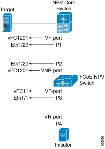
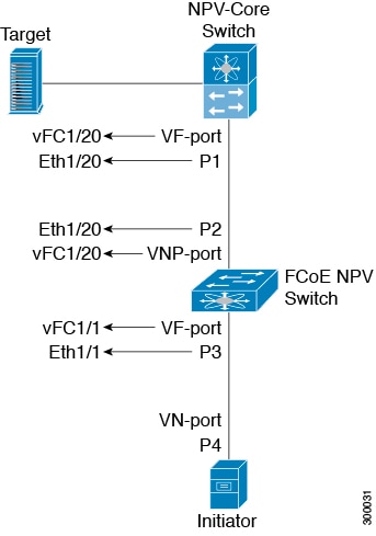
  • The switch to act as an N-port virtualizer (NPV) connected to the core switch (FCF).

  • The core switch (FCF) to view the NPV switch as another host.

  • The multiple hosts connected to the NPV switch are presented as virtualized N-ports on the core switch (FCF).

FCoE NPV Benefits

FCoE NPV provides the following:

  • FCoE NPV provides the advantages of NPV to FCoE deployments (such as preventing domain ID sprawl and reducing Fiber-Channel Forwarder (FCF) table size).

  • FCoE NPV provides a secure connect between FCoE hosts and the FCoE FCF.

  • FCoE NPV does not have the management and troubleshooting issues that are inherent to managing hosts remotely at the FCF.

  • FCoE NPV implements FIP snooping as an extension to the NPV function while retaining the traffic-engineering, VSAN-management, administration, and trouble shooting aspects of NPV.

FCoE NPV Features

The following are the FCoE NPV features:

  • Automatic load balance of server logins

    • The server interfaces (Host logins) are distributed in a round robin fashion among the available multiple uplinks (NP ports or external-interfaces).

    • You can enable disruptive automatic load balancing to load balance the existing server interfaces (hosts) to newly added NP uplink interfaces.

      Example:

      switch(config)# npv auto-load-balance disruptive
      
  • Traffic mapping

    • You can specify the NP uplinks that a server interface can use to connect to core switches.

    • If the current mapped uplink goes down, the server does not log in through other available uplinks.

      Example:

      switch(config)# npv traffic-map server-interface vfc2/1 external-interface vfc2/1
      
  • FCoE forwarding in the FCoE NPV bridge.

  • FCoE NPV supports the Data Center Bridging Exchange Protocol (DCBX).

  • FCoE frames received over VNP ports are forwarded only if the L2_DA matches one of the FCoE MAC addresses assigned to hosts on the VF ports.


Note

FCoE NPV over port channel VNP ports use automatic traffic mapping only for FIP negotiations. FCoE traffic distribution over port channel VNP ports is based on the computed hash value.


Note

Enabling feature-set fcoe-npv or feature-set fcoe on a Cisco Nexus 93180YC-FX switch may disrupt in-service software upgrade (ISSU).


Fibre Channel Slow Drain Device Detection and Congestion Avoidance

The data traffic between the end devices in Fibre Channel over Ethernet (FCoE) uses link level and per-hop based flow control. When the slow devices are attached to the fabric, the end devices do not accept the frames at a configured rate. The presence of the slow devices leads to traffic congestion on the links. The traffic congestion affects the unrelated flows in the fabric that use the same inter-switch links (ISLs) for its traffic, even though the destination devices do not experience the slow drain.

Slow drain device detection and congestion avoidance is supported on below platform switches:

  • N9K-C93180YC-EX

  • N9K-X9732C-EX Line Card

  • N9K-C93180LC-EX

  • N9K-C93180YC-FX

  • N9K-X9736C-FX line card


Note

Slow drain device detection and congestion avoidance is not supported on FEX ports.


Licensing Requirements

For a complete explanation of Cisco NX-OS licensing recommendations and how to obtain and apply licenses, see the Cisco NX-OS Licensing Guide.

VNP Ports

Connectivity from an FCoE NPV bridge to the FCF is supported only over point-to-point links. These links can be individual Ethernet interfaces or port channel interfaces. For each FCF connected to an Ethernet/port-channel interface, a vFC interface must be created and bound to it. These vFC interfaces must be configured as VNP ports.

On the VNP port, the FCoE NPV bridge emulates an FCoE-capable host with multiple enodes, each with a unique enode MAC address. By default, the VNP port is enabled in trunk mode.

Multiple VSANs can be configured on the VNP port. The FCoE VLANs that correspond to the VNP port VSANs must be configured on the bound Ethernet interface.


Note

VNP ports on the Cisco Nexus 9000 Series device emulate an FCoE capable host with multiple Ethernet nodes, each with unique Fabric Provided MAC-Addresses (FPMA).


Guidelines and Limitations for Configuring FCoE NPV

Configuring FCoE NPV has the following configuration guidelines and limitations:

  • The FCoE NPV on N9K-X9732C-EX and N9K-X9736C-FX line cards is supported only with fabric modules N9K-C9508-FM-E or N9K-C9504-FM-E.

  • Enabling FCoE NPV requires:

    • Enabling the LLDP feature using feature lldp . LLDP is not enabled by default.

    • Downloading and installing FCOE_NPV_PKG (license).

    • Installing the FCoE feature set using the install feature-set fcoe-npv command.

    • Enabling the NPV feature set using the feature-set fcoe-npv command.

  • FCoE is not supported on Cisco Nexus Platform switches with 10BASE-T interfaces, for example, Cisco Nexus 93108TC-FX switches.

  • Fibre Channel N-port Virtualization (NPV) can co-exist with VXLAN on different fabric uplinks but on same or different front panel ports on the Cisco Nexus 93180YC-FX switches.

  • The first operational port of the port-channel (non-lacp) must be shut down before being removed. Otherwise, the vfc-po binding of that port-channel may go down.

  • The 6 QSFP+ ports (40G) can be used as either uplink ports or server ports on the N9k-C92160YC, N9K-C93180YC-FX, and N9K-C93180YC-EX platforms.

  • It is mandatory to do a TCAM Reservation (as mentioned here: Configuring QoS for no-drop Support) for FCoE NPV to work.

  • The show commands with the internal keyword are not supported.

  • FCoE NPV supports a VNP port bound to an Ethernet interface, port-channel, or break-out interface.

  • FCoE NPV is supported on the following Cisco Nexus 9300 Series devices and Cisco Nexus 9500 Series devices (NX-OS 7.0(3)I3(1) and later):

    • Nexus C9332PQ switch

    • Nexus C9372PX switch

    • Nexus C9372PX-E switch

    • Nexus C9396PX switch

    • Nexus C9504 and Nexus C9508 switches with the following line cards:

      • X9432PQ

      • X9464PX

      • X9536PQ

      • X9564PX

      • X9636PQ

  • FCoE NPV is supported on the following Cisco Nexus 9200 and Cisco Nexus 9300 Series devices (NX-OS 7.0(3)I5(1) and later):

    • N9K-C92160YC-X

    • N9K-C9272Q


      Note

      The N9k-9272Q switch has 72 ports. Ports 1 to 36 only operate in 40-Gb mode. Ports 37 to 71 support breakout to 4 x 10-Gb connectivity. Port 72 does not support breakout.


    • N9K-C9236C

    • N9K-C93180YC-EX

  • FCoE NPV is supported on the following Cisco Nexus 9500 Series devices (NX-OS 7.0(3)I6(1) and later):

    • N9K-C93180LC-EX

  • FCoE NPV is supported on the following Cisco Nexus 9500 Series devices (NX-OS 7.0(3)I5(2) and later):

    • N9K-X9732C-EX

  • FCoE NPV is not supported on the following Cisco Nexus 9500 Series devices (NX-OS 7.0(3)I5(2) and later):

    • N9K-X97160YC-EX

    • N9K-X9736C-EX

  • FCoE NPV supports the following FEX (NX-OS 7.0(3)I5(1) and later):

    • N2K-C2348UPQ

    • N2K-C2232PP

    • N2K-B22IBM-P

    • N2K-B22HP-P

  • Starting from Release 7.0(3)I6(1), the N9K-C93180LC-EX supports FCoE NPV on FEX with only one FEX model: the N2K-C2348UPQ.

  • Starting from Release 7.0(3)I7(1), the N9K-C93180YC-FX supports FCoE NPV.

  • Starting from Release 7.0(3)I7(2), the N9K-X9736C-FX line card supports FCoE NPV.

  • The following switches do not support FEX (NX-OS 7.0(3)I5(1) and later):

    • N9K-C92160YC-X

    • N9K-C9272Q

    • N9K-C9236C

    • N9K-C93180YC-FX

  • On the following models, the 40G GEM (Gigabit Ethernet Expansion Module) ports cannot be used to connect FCoE hosts (F ports). They can be used as FCoE uplink ports (VNP Ports):

    • Cisco Nexus 9332PQ switch

    • Cisco Nexus 9372PX switch

    • Cisco Nexus 9372PX-E switch

    • Cisco Nexus 9396PX switch

    • N9K-X9464PX line cards

    • N9K-X9564PX line cards

  • Application Leaf Engine (ALE) 40G ports cannot be used to connect FCoE hosts (F ports) and do not support Converged Network Adapters (CNA).

  • FCoE NPV does not support nested NPV.

  • FCoE NPV supports FLOGI/FDISC (nested NPIV).

    To support multiple FLOGI from a single port, you must enable the NPIV feature to accommodate hosts or servers that send FDISC followed by FLOGI.

    Examples of commands to enable/disable and display status of the NPIV feature:

    • 
      switch(config)# feature npiv 
      switch# show feature | include npiv
      npiv                   1          enabled 
      switch# 
      
    • 
      switch# show npv status 
      
      npiv is enabled
      
      disruptive load balancing is disabled
      
      External Interfaces:
      ====================
        Interface: vfc-po100, State: Trunking
              VSAN:    1, State: Waiting For VSAN Up
              VSAN:    2, State: Up
              VSAN:    3, State: Up, FCID: 0x040000
        Interface: vfc1/49, State: Down
      
        Number of External Interfaces: 2
      
    • 
      switch(config)# no feature npiv 
      switch# show feature | include npiv
      npiv                   1          disabled
      switch#
      
  • When configuring QoS policies for an active-active FEX topology that is enabled for FCoE, you must configure the QoS policies on the FEX HIF port on both VPC peers to avoid unpredictable results (Release 7.0(3)I5(1) and later releases).


    Note

    Only the following support an active-active FEX topology:

    • N2K-C2232PP

    • N2K-C2348UPQ

    • NB22IBM

    • NB22HP


Configuring FCoE NPV

Configuring QoS for no-drop Support

A qos ingress policy is used to mark ingress FCoE frames. The qos ingress policy must be applied to the interfaces that handle FCoE traffic (such as, all ethernet/port-channel interfaces bound to vFCs).


Note

Check to ensure that the port qos region has hardware TCAM space reserved.

This step is mandatory for FCoE NPV to work.

  • Reserve TCAM space for the QoS region.

    You may need to acquire TCAM space reserved for other regions (such as the l3qos region).

  • Save the configuration.

  • Reload the line cards or switch.

  • Confirm the port qos region TCAM space.

  • Example for TCAM carving on 9332PQ,9372PX, 9372PX-E and 9396X:

    
    hardware access-list tcam region qos 256
    hardware access-list tcam region fex-qos 256
    hardware access-list tcam region fcoe-ingress 256
    hardware access-list tcam region fcoe-egress 256
  • Example for TCAM carving on N9K-C92160YC-X, N9K-C9272Q, N9K-C9236C, N9K-C93180YC-EX, or N9K-C93180YC-FX:

    hardware access-list tcam region ing-racl 1536
    hardware access-list tcam region ing-redirect 256
    
  • Example for TCAM carving on N9K-C92160YC-X, N9K-C9272Q, N9K-C9236C, N9K-C93180YC-EX, or N9K-C93180YC-FX:

    
    hardware access-list tcam region ing-racl 1536
    hardware access-list tcam region ing-redirect 256
    

Example:


switch# show hardware access-list tcam region | i "IPV4 Port QoS \[qos\] size"
IPV4 Port QoS [qos] size = 0 /*** Value is 0; No reserved TCAM space.***/

switch# config
switch(config)# hardware access-list tcam region qos 256

Warning: Please reload all linecards for the configuration to take effect

switch# copy running-config startup-config

switch# reload

switch# show hardware access-list tcam region | i "IPV4 Port QoS \[qos\] size"
IPV4 Port QoS [qos] size = 256

Configuring FCoE QoS policies

  • There are four types of FCoE default policies: network-qos, output queuing, input queuing, and qos.

  • You can activate the FCoE default policies by enabling the FCoE-NPV feature using the feature-set fcoe-npv command and remove the FCoE default policies by executing the no feature-set fcoe-npv command.

  • Before entering no feature-set fcoe-npv , remove all FCoE policies from the interface and system level. The no feature-set fcoe-npv command is allowed only when there are no FC ports configured.


    Note

    Cisco recommends using the FCoE default policies. All policies applied must be of the same type, either 4q or 8q mode, and must be explicitly applied or removed at the system and interface level.


  • When configuring QoS policies for an active-active FEX topology that is enabled for FCoE, you must configure the QoS policies on the FEX HIF port on both VPC peers to avoid unpredictable results.

  • To use a different queue or cos value for FCoE traffic, create user-defined policies.

Configuring QoS Policies for FCoE

  • You can configure a QoS policy by following one of these methods:

    • Predefined policies—You can apply a predefined QoS policy: default-fcoe-in-policy .


      Note

      No policy will be applied by default for FCoE.


    • User-defined policy—You can create a QoS policy that conforms to one of the system-defined policies.

Configuring System-wide QoS Policy


Note

The network-qos policy and output/input queuing policies should be applied at the system level and the qos policy should be applied at the interface level, for every interface that carries the FCoE traffic.


switch(config)# system qos
switch(config-sys-qos)# service-policy type queuing input default-fcoe-in-que-policy
switch(config-sys-qos)# service-policy type queuing output { default-fcoe-8q-out-policy | default-fcoe-out-policy }
switch(config-sys-qos)# service-policy type network-qos { default-fcoe-8q-nq-policy | default-fcoe-nq-policy }

Configuration Example for user-defined policies


switch(config)# policy-map type network-qos fcoe_nq
switch(config-pmap-nqos)# class type network-qos c-nq1
switch(config-pmap-nqos-c)# pause pfc-cos 3
switch(config-pmap-nqos-c)# mtu 9216
switch(config-pmap-nqos-c)# class type network-qos c-nq2
switch(config-pmap-nqos-c)# mtu 1500
switch(config-pmap-nqos-c)# class type network-qos c-nq3
switch(config-pmap-nqos-c)# mtu 1500
switch(config-pmap-nqos-c)# class type network-qos c-nq-default
switch(config-pmap-nqos-c)# mtu 1500
switch(config-pmap-nqos-c)# exit
switch(config-pmap-nqos)# exit
switch(config)#
switch(config)# policy-map type queuing fcoe-in-policy
switch(config-pmap-que)# class type queuing c-in-q1
switch(config-pmap-c-que)# bandwidth percent 50
switch(config-pmap-c-que)# class type queuing c-in-q-default
switch(config-pmap-c-que)# bandwidth percent 50
switch(config-pmap-c-que)# exit
switch(config)
switch(config)# policy-map type queuing fcoe-out-policy
switch(config-pmap-que)# class type queuing c-out-q3
switch(config-pmap-c-que)# priority level 1
switch(config-pmap-c-que)# class type queuing c-out-q-default
switch(config-pmap-c-que)# bandwidth remaining percent 50
switch(config-pmap-c-que)# class type queuing c-out-q1
switch(config-pmap-c-que)# bandwidth remaining percent 50
switch(config-pmap-c-que)# class type queuing c-out-q2
switch(config-pmap-c-que)# bandwidth remaining percent 0
switch(config-pmap-c-que)# exit
switch(config)#
switch(config)# class-map type qos match-any fcoe
switch(config-cmap-qos)# match protocol fcoe
switch(config-cmap-qos)# match cos 3
switch(config-cmap-qos)# exit
switch(config)#
switch(config)# policy-map type qos fcoe_qos_policy
switch(config-pmap-qos)# class fcoe
switch(config-pmap-c-qos)# set cos 3
switch(config-pmap-c-qos)# set qos-group 1
switch(config-pmap-c-qos)# exit
switch(config-pmap-qos)# exit
switch(config)#
switch(config)# system qos
switch(config-sys-qos)# service-policy type queuing input fcoe-in-policy 
switch(config-sys-qos)# service-policy type queuing output fcoe-out-policy 
switch(config-sys-qos)# service-policy type network-qos fcoe_nq

Note

The set cos 3 command under the QOS policy is mandatory only when there are native fiber channel ports and the command is applicable only for N9K-C93180YC-FX platform. For all the other Cisco Nexus 9000 Platform switches, this step is optional.


Note

When FEX is connected:

  • Apply the QoS policy to the system level and to the HIF port to honor the pause frames in the FCoE traffic.

  • 8q policies are not supported when FEX is online.

    
    switch(config)# system qos
    switch(config-sys-qos)# service-policy type queuing input policy-name
    switch(config-sys-qos)# service-policy type queuing output policy-name
    switch(config-sys-qos)# service-policy type network-qos policy-name
    switch(config-sys-qos)# service-policy type qos input policy-name
     

Applying the ingress QoS policy to each Ethernet/port-channel interface that is bound to vFC interface for FCoE.


switch(config)# interface ethernet 2/1
switch(config-if)# switchport mode trunk
switch(config-if)# mtu 9216 /* Or maximum allowed value */
switch(config-if)# service-policy type qos input { default-fcoe-in-policy | fcoe_qos_policy }
switch(config-if)# exit
switch(config)#

Note

The QoS policy needs to be attached to an HIF interface or the port-channel of an HIF interface:

  • HIF interface

    
    interface "HIF port"
    service-policy type qos input policy-name
    
  • Port-channel of an HIF interface

    
    interface port-channel
    service-policy type qos input policy-name 


Note

The following platforms do not support 8q policies:

  • Cisco Nexus C9332PQ switch

  • Cisco Nexus C9372PX switch

  • Cisco Nexus C9396PX switch

  • Cisco Nexus C9372PX-E switch

  • Cisco Nexus X9536PQ line card

  • Cisco Nexus X9564PX line card


Configuring VLAN-VSAN Mapping

VSANs and VLANs are required and the VSANs need to be mapped to the VLANs.

One VLAN can be mapped to only one VSAN and vice versa. The VSANs can then be added to F and NP vFC interfaces (described in a subsequent section).

  • Example of VSAN creation:

    
    switch(config)#
    switch(config)# vsan database
    switch(config-vsan-db)# vsan 10
    switch(config-vsan-db)#
    
  • Example VLAN configuration and binding to FCoE VSAN:

    
    switch(config)# vlan 10
    switch(config-vlan)# fcoe vsan 10
    switch(config-vlan)# exit
    switch(config)#
    

Explicit vFC Configuration

An explicit vFC interface is a vFC interface where the bound ethernet/port-channel interface is explicitly configured. (The interface ID range is 1-8192.)


Note

The port VSAN of the vFC and the native VLAN of the ethernet port should not be mapped to each other in a VLAN-VSAN mapping; this will break the FCoE path completely.


  • Example of explicit vFC bound to interface Ethernet:

    
    switch# configure terminal
    switch(config)# interface vfc 21
    switch(config-if)# bind interface ethernet 2/1
    
    
  • Example of explicit vFC bound to interface port-channel:

    
    switch# configure terminal
    switch(config)# interface vfc 100
    switch(config-if)# bind interface port-channel 100
    
    
  • Example of explicit vFC bound to break-out port:

    
    switch# configure terminal
    switch(config)# interface vfc 111
    switch(config-if)# bind interface ethernet 1/1/1
    
    
  • Example of NP interface configuration using explicit vFC:

    
    switch# configure terminal
    switch(config)# interface vfc21
    switch(config-if)# switchport mode NP
    switch(config-if)# switchport trunk allowed vsan 10 /* optional; for restricting VSANs */
    
  • Example of NP interface configuration using explicit bound port-channel interface:

    
    switch# configure terminal
    switch(config)# interface vfc152
    switch(config-if)# bind interface port-channel152
    switch(config-if)# switchport mode NP
    switch(config-if)# switchport trunk allowed vsan 2
    switch(config-if)# switchport trunk mode on 
    switch(config-if)# no shutdown
    
  • Example of F interface configuration using explicit vFC:

    
    switch# configure terminal
    switch(config)# interface vfc15
    switch(config-if)# bind interface ethernet 1/5
    switch(config-if)# switchport mode F /* Default mode is F */
    switch(config-if)# switchport trunk allowed vsan 10
    switch (config-if)# exit
    switch (config)# vsan database
    switch(config-vsan-db)# vsan 10 interface vfc15
    switch(config-vsan-db)# exit

Implicit vFC Configuration

An implicit vFC interface is a vFC interface that has an ID with the format slot/port or unit/slot/port or port-channel id . When this vFC is created, the Ethernet interface slot/port or unit/slot/port or port-channel id is automatically (implicitly) bound to the interface. The running configuration displays the bound Ethernet/port-channel interface. If the Ethernet /port-channel interface does not exist or it is bound to another explicit vFC interface, the vFC creation fails with an error.


Note

  • The port VSAN of the vFC and the native VLAN of the Ethernet port should not be mapped to each other in a VLAN-VSAN mapping. It breaks the FCoE path completely.

  • When a vFC is created through the Cisco DCNM (Data Center Network Manager), the vFC interface goes to VSAN 4094 (isolated), whereas when a vFC is created through the CLI, the vFC interface goes to VSAN 1. The ethernet interface should be up before configuring implicit vFC through the Cisco DCNM because once the vFC goes to VSAN 4094, it cannot be brought up.


  • Example of implicit vFC bound to interface Ethernet:

    
    switch# configure terminal
    switch(config)# interface vfc 2/1
    
    
  • Example of implicit vFC bound to interface port-channel:

    
    switch# configure terminal
    switch(config)# interface vfc-port-channel 100
    
    
  • Example of implicit vFC bound to break-out port:

    
    switch# configure terminal
    switch(config)# interface vfc 1/1/1
    
    
  • Example of NP interface configuration using implicit vFC:

    
    switch# configure terminal
    switch(config)# interface vfc1/1/1
    switch(config-if)# switchport mode NP
    switch(config-if)# switchport trunk allowed vsan 10 /* optional; for restricting VSANs */
    
  • Example of F interface configuration using implicit vFC:

    
    switch# configure terminal
    switch(config)# interface vfc1/1/1
    switch(config-if)# switchport mode F /* Default mode is F */
    switch(config-if)# switchport trunk allowed vsan 10
    switch (config-if)# exit
    switch (config)# vsan database
    switch(config-vsan-db)# vsan 10 interface vfc1/1/1
    switch(config-vsan-db)# exit

Configuring the FCoE NPV Core Switch

Perform the following steps to configure an FCoE NPV core switch.

Procedure

  Command or Action Purpose
Step 1

configure terminal

Enters configuration mode.

Step 2

(Optional) switchto vdc vdc-name

(Optional)

Switch to storage VDC.

Note 

This step is required only when a Cisco Nexus 7000 Series switch is used as the core switch.

Step 3

feature npiv

Enable NPIV.

Step 4

(Optional) feature fport-channel-trunk

(Optional)

Enables F port channel trunking.

Step 5

interface ethernet slot/port

Enters interface configuration mode.

Step 6

switchport

Configures the interface as a Layer 2 interface and deletes any configuration specific to Layer 3 on this interface.

Step 7

no switchport

Configures the interface as a Layer 3 interface and deletes any configuration specific to Layer 2 on this interface.

Step 8

switchport mode trunk

Set physical interface mode to trunk.

Step 9

mtu 9216

Configure MTU as 9216. You must configure MTU as 9216 or maximum allowed MTU size

Note 

This step is required only when a Cisco Nexus C93180YC-FX switch is used as the core switch.

Step 10

service-policy type {network-qos | qos | queuing} [input | output] fcoe default policy-name

Specifies the QoS policy on the port to a no drop policy.

Note 

This step is required only when a Cisco Nexus C93180YC-FX switch is used as the core switch.

Step 11

exit

Exits the interface mode.

Step 12

interface vfc vfc-id

Enters interface configuration mode.

Step 13

switchport mode f

Set vFC port mode to VF

Step 14

bind interface ethernet slot/port

Binds a ethernet interface to a vFC

Important 

The bind interface ethernet command is not required for an implicit vFC configuration.

Step 15

exit

Exits the interface configuration mode.

Step 16

vsan database

Enters VSAN configuration mode.

Step 17

vsan vsan-id

Create VSAN

Step 18

vsan vsan-id interface vfc vfc-id

Add vFC into VSAN.

Step 19

exit

Exits the VSAN configuration mode.

Step 20

vlan vlan-id

Enters VLAN configuration mode.

Step 21

fcoe vsan vsan-id

Creates FCoE VLAN and map FCoE VLAN to VSAN.

Step 22

exit

Exits the VLAN configuration mode.

Configuring the FCoE NPV Edge Switch

Perform the following steps to configure an FCoE NPV edge switch.

Procedure

  Command or Action Purpose
Step 1

install feature-set fcoe-npv

Installs FCoE NPV.

Step 2

feature-set fcoe-npv

Enables FCoE NPV.

Note 

When enabling FCoE NPV for Cisco NX-OS 7.0(3)I4(1) and later releases, the following BCM settings are required per FCoE VLAN:

LEARN_DISABLE=1
 L2_NON_UCAST_DROP=1 
 L2_MISS_DROP=1
  • Ethernet VLANs do not require these BCM settings.

Step 3

[no] feature lldp

Enables or disables LLDP on the device. LLDP is disabled by default.

Step 4

vsan database

Enters VSAN configuration mode.

Step 5

vsan vsan-id

Creates VSAN.

Step 6

exit

Exits the VSAN configuration mode.

Step 7

vlan vlan-id

Enters VLAN configuration mode.

Step 8

fcoe vsan vsan-id

Creates FCoE VLAN and map it to VSAN.

Step 9

exit

Exits the VSAN configuration mode.

Step 10

interface ethernet slot/port

Enters interface configuration mode.

Step 11

switchport

To put an interface that is in Layer 3 mode into Layer 2 mode for Layer 2 configuration, use the switchport command in interface configuration mode. To put an interface into Layer 3 mode, use the no form of this command.

Step 12

switchport mode trunk

Sets switch side physical interface to trunk mode.

Step 13

mtu 9216

Configure MTU as 9216. You must configure MTU as 9216 or maximum allowed MTU size

Step 14

service-policy type {network-qos | qos | queuing} [input | output] fcoe default policy-name

Specifies the QoS policy on the port to a no drop policy.

Step 15

exit

Exits the VSAN configuration mode.

Step 16

interface vfc vfc-id

Enters interface configuration mode.

Step 17

switchport mode NP

Sets vFC port mode to VNP.

Step 18

bind interface ethernet slot/port

Sets vFC port mode to VNP.

Important 

The bind interface ethernet command is not required for an implicit vFC configuration.

Step 19

exit

Exits the interface configuration mode.

Step 20

interface ethernet slot/port

Enters interface configuration mode.

Step 21

switchport

To put an interface that is in Layer 3 mode into Layer 2 mode for Layer 2 configuration, use the switchport command in interface configuration mode. To put an interface into Layer 3 mode, use the no form of this command.

Step 22

switchport mode trunk

Sets server side physical interface to trunk mode.

Step 23

mtu 9216

Configure MTU as 9216.

Step 24

service-policy type {network-qos | qos | queuing} [input | output] fcoe default policy-name

Specifies the default FCoE policy map to use as the service policy for the system.

Step 25

exit

Exits the interface configuration mode.

Step 26

interface vfc vfc-id

Enters interface configuration mode.

Step 27

switchport mode f

Sets the mode to F on a Fibre Channel interface.

Step 28

switchport trunk mode on

Sets server side physical interface to trunk mode.

Step 29

switchport trunk allowed vsan vsan-id

Configure vFC port to allow VSAN vsan-id.

Step 30

bind interface ethernet slot/port

Configures vFC port to allow VSAN vsan-id.

Important 

The bind interface ethernet command is not required for an implicit vFC configuration.

Step 31

no shutdown

Keeps the Fibre Channel interface active

Step 32

exit

Exits the interface configuration mode.

Step 33

vsan database

Enters VSAN configuration mode.

Step 34

vsan vsan-id interface vfc vfc-id

Adds port VSAN vsan-id to VF port.

Step 35

vsan vsan-id interface vfc vfc-id

Add VNP port to VSAN vsan-id.

Note 

This step is optional. The default port VSAN is 1 and is preferable for the VNP port.

Step 36

exit

Exits the VSAN configuration mode.

Configuring a Pause Frame Timeout Value

You can enable or disable a pause frame timeout value on a port. The system periodically checks the ports for a pause condition and enables a pause frame timeout on a port if it is in a continuous pause condition for a configured period of time. This situation results in all frames that come to that port getting dropped in the egress. This function empties the buffer space in the ISL link and helps to reduce the fabric slowdown and the congestion on the other unrelated flows using the same link.


Note

  • N9K-C93180YC-EX

  • N9K-C93180YC-FX

  • N9K-C93180LC-EX

  • N9K-X9732C-EX

  • N9K-X9736C-FX

  • The QoS policy for uplink ports and server or host interfaces should be same for the slow drain feature to be operational.


When a pause condition is cleared on a port or when a port flaps, the system disables the pause frame timeout on that particular port.

The pause frame timeout is disabled by default. We recommend that you retain the default configuration for the ISLs and configure a value that does not exceed the default value for the edge ports.

For a faster recovery from the slow drain device behavior, you should configure a pause frame timeout value because it drops all the frames in the edge port that face the slow drain whether the frame is in the switch for a congested timeout or not. This process instantly clears the congestion in the ISL.

Use the no system default interface pause timeout milliseconds mode edge command to disable the pause frame timeout value on the edge ports. The default pause timeout value is 500 milliseconds.

Procedure

  Command or Action Purpose
Step 1

switch# configure terminal

Enters global configuration mode.

Step 2

switch# system default interface pause timeout milliseconds mode edge

Configures a new pause frame timeout value in milliseconds and the port mode for the device.

Note 

Timeout value is specified in multiples of 100 (range is 100-500).

Note 

The system default interface pause timeout milliseconds mode core command is not supported.

Step 3

switch# system default interface pause mode edge

Configures the default pause frame timeout value in milliseconds and the port mode for the device.

Note 

Only the system default interface pause milliseconds mode edge command is supported.

The system default interface pause milliseconds mode core command is not supported.

Step 4

switch# no system default interface pause timeout milliseconds mode edge

Disables the pause frame timeout for the device.

Step 5

switch# no system default interface pause mode edge

Disables the default pause frame timeout for the device.

Example

This example shows how to configure a pause frame timeout value:

switch# configure terminal
switch(config)# system default interface pause timeout 500 mode edge
switch(config)# system default interface pause mode edge
switch(config)# no system default interface pause timeout 500 mode edge
switch(config)# no system default interface pause mode edge
switch(config)# end

This example shows how to display pause frame timeout information:


switch#(config-if)# attach module 1
module-1# sh creditmon interface ethernet 1/35

Ethernet1/35: PORT is EDGE, xoff_hits=2
         flush-status        : OFF
         total_xoff_hits     : 2
         (cntr) pause frames : 832502
         (cntr) pause quanta : 1962909 milli-seconds
         (cntr) force drops  : 94320764
         (cntr-pg) to_drops  : 0
         DBG_xoff_hit_cnt    : 0
         DBG_xoff_hit_time   : 274
         DBG_port_fc_mode    : 2
         DBG_force_tmo_val   : 300 milli-seconds
         CFG_congestion_tmo  : 0 milli-seconds

This example shows how to display pause frame timeout information:


switch(config-if)# attach module 1
module-1#
module-1# sh creditmon interface all
Ethernet1/1: PORT is NONE, xoff_hits=0
Ethernet1/2: PORT is NONE, xoff_hits=0
Ethernet1/3: PORT is NONE, xoff_hits=0
Ethernet1/4: PORT is NONE, xoff_hits=0
Ethernet1/5: PORT is NONE, xoff_hits=0
Ethernet1/6: PORT is NONE, xoff_hits=0
Ethernet1/7: PORT is NONE, xoff_hits=0
Ethernet1/8: PORT is NONE, xoff_hits=0
Ethernet1/9: PORT is NONE, xoff_hits=0
Ethernet1/10: PORT is NONE, xoff_hits=0
Ethernet1/11: PORT is NONE, xoff_hits=0
Ethernet1/12: PORT is NONE, xoff_hits=0
Ethernet1/13: PORT is NONE, xoff_hits=0
Ethernet1/14: PORT is NONE, xoff_hits=0
Ethernet1/15: PORT is NONE, xoff_hits=0
Ethernet1/16: PORT is NONE, xoff_hits=0
Ethernet1/17: PORT is NONE, xoff_hits=0
Ethernet1/18: PORT is NONE, xoff_hits=0
Ethernet1/19: PORT is NONE, xoff_hits=0
Ethernet1/20: PORT is NONE, xoff_hits=0
Ethernet1/21: PORT is NONE, xoff_hits=0
Ethernet1/22: PORT is NONE, xoff_hits=0
Ethernet1/23: PORT is NONE, xoff_hits=0
Ethernet1/24: PORT is NONE, xoff_hits=0
Ethernet1/25: PORT is NONE, xoff_hits=0
Ethernet1/26: PORT is NONE, xoff_hits=0
Ethernet1/27: PORT is NONE, xoff_hits=0
Ethernet1/28: PORT is NONE, xoff_hits=0
Ethernet1/29: PORT is NONE, xoff_hits=0
Ethernet1/30: PORT is NONE, xoff_hits=0
Ethernet1/31: PORT is NONE, xoff_hits=0
Ethernet1/32: PORT is NONE, xoff_hits=0
Ethernet1/33: PORT is NONE, xoff_hits=0
Ethernet1/34: PORT is NONE, xoff_hits=0
Ethernet1/35: PORT is NONE, xoff_hits=0
Ethernet1/36: PORT is NONE, xoff_hits=0
Ethernet1/37: PORT is NONE, xoff_hits=0
Ethernet1/38: PORT is NONE, xoff_hits=0
Ethernet1/39: PORT is NONE, xoff_hits=0
Ethernet1/40: PORT is NONE, xoff_hits=0
Ethernet1/41: PORT is NONE, xoff_hits=0
Ethernet1/42: PORT is NONE, xoff_hits=0
Ethernet1/43: PORT is NONE, xoff_hits=0
Ethernet1/44: PORT is NONE, xoff_hits=0
Ethernet1/45: PORT is NONE, xoff_hits=0
Ethernet1/46: PORT is NONE, xoff_hits=0
Ethernet1/47: PORT is NONE, xoff_hits=0
Ethernet1/48: PORT is NONE, xoff_hits=0
Ethernet1/49: PORT is NONE, xoff_hits=0
Ethernet1/49/2: PORT is NONE, xoff_hits=0
Ethernet1/49/3: PORT is NONE, xoff_hits=0
Ethernet1/49/4: PORT is NONE, xoff_hits=0
Ethernet1/50: PORT is NONE, xoff_hits=0
Ethernet1/50/2: PORT is NONE, xoff_hits=0
Ethernet1/50/3: PORT is NONE, xoff_hits=0
Ethernet1/50/4: PORT is NONE, xoff_hits=0
Ethernet1/51: PORT is NONE, xoff_hits=0
Ethernet1/51/2: PORT is NONE, xoff_hits=0
Ethernet1/51/3: PORT is NONE, xoff_hits=0
Ethernet1/51/4: PORT is NONE, xoff_hits=0
Ethernet1/52: PORT is NONE, xoff_hits=0
Ethernet1/52/2: PORT is NONE, xoff_hits=0
Ethernet1/52/3: PORT is NONE, xoff_hits=0
Ethernet1/52/4: PORT is NONE, xoff_hits=0
Ethernet1/53: PORT is NONE, xoff_hits=0
Ethernet1/53/2: PORT is NONE, xoff_hits=0
Ethernet1/53/3: PORT is NONE, xoff_hits=0
Ethernet1/53/4: PORT is NONE, xoff_hits=0
Ethernet1/54: PORT is NONE, xoff_hits=0
Ethernet1/54/2: PORT is NONE, xoff_hits=0
Ethernet1/54/3: PORT is NONE, xoff_hits=0
Ethernet1/54/4: PORT is NONE, xoff_hits=0

module-1#

This example shows syslog messages that are displayed when a pause frame timeout occurs:


2016 Sep 14 09:58:05 N93180YC-2 %TAHUSD-SLOT1-2-TAHUSD_SYSLOG_CRIT: 
           Ethernet1/35, slowdrain xoff hit  ON (total xoff-hits:1)
 
2016 Sep 14 09:59:21 N93180YC-2 %TAHUSD-SLOT1-2-TAHUSD_SYSLOG_CRIT: 
           Ethernet1/35, slowdrain xoff hit OFF (last  xoff-time:76 seconds)

Verifying the FCoE NPV Configuration

To display FCoE/VPC configuration information, perform one of the following:

Command

Purpose

show fcoe

Displays status of Fibre Channel over Ethernet (FCoE) parameters on the switch.

show fcoe database

Displays content of the Fibre Channel over Ethernet (FCoE) database.

show int vfc vfc-id

Displays vFC interface information.

To display NPV configuration information, perform one of the following:

Command

Purpose

show npv status

Displays N Port Virtualization (NPV) current status

show npv traffic-map

Displays N Port Virtualization (NPV) traffic map.

show npv external-interface-usage server-interface if

Displays external vFC interfaces (NP interfaces) designated/allocated to the server vFC interface if through automatic or static allocation.

show npv external-interface-usage

Displays external vFC interfaces (NP interfaces) designated/allocated to all available server vFC interfaces through automatic or static allocation.

show npv flogi-table interface if

Displays host FLOGI table that lists server interface; VSAN; fcid allocated to the initiator connected to the server interface; PWWN and NWWN of initiator; and external interface/gateway on NPV switch designated to the server interface.

show npv flogi-table vsan vsan

Displays information about N Port Virtualization (NPV) FLOGI session specific to the VSAN.

show npv flogi-table

Displays information about N Port Virtualization (NPV) FLOGI session.

show fcoe-npv issu-impact

Displays information about VNP ports where FKA is disabled.

FCoE NPV Core Switch and FCoE NPV Edge Switch Configuration Example

Figure 1. Configuring FCoE NPV Core Switch and FCoE NPV Edge Switch


  • Configure NPV core switch:

    • Enable NPIV

      
      npv-core(config)# feature npiv
      
    • Set physical interface mode to trunk

      npv-core(config)# interface Eth 1/20
      npv-core(config)# switchport 
      npv-core(config)# switchport mode trunk
      npv-core(config)# mtu 9216
      npv-core(config)# service-policy type qos input default-fcoe-in-policy

      Note

      The steps switchport, MTU and service-policy are required only when a Cisco Nexus C93180YC-FX switch is used as the core switch


    • Set vFC port mode of P1 to VF

      npv-core(config)# interface vfc1201
      npv-core(config)# bind interface Eth1/20
      npv-core(config)# switchport mode F
    • Create VSAN and add vFC into VSAN

      npv-core(config)# vsan database
      npv-core(config-vsan-db)# vsan 100
      npv-core(config-vsan-db)# vsan 100 interface vfc1201
    • Create FCoE VLAN & map it to VSAN

      npv-core(config)# vlan 100
      npv-core(config-vlan)# fcoe vsan 100
  • Configure FCoE NPV switch:

    • Install FCoE NPV

      npv(config)# install feature-set fcoe-npv
    • Enable FCoE NPV

      npv(config)# feature-set fcoe-npv
    • Create VSAN

      npv(config)# vsan database
      npv(config-vsan-db)# vsan 100
    • Create FCoE VLAN and map it to VSAN

      npv(config)# vlan 100
      npv(config-vlan)# fcoe vsan 100
    • Set switch side physical interface to trunk mode

    • npv-core(config)# interface Eth 1/20
      npv-core(config)# switchport mode trunk
      npv-core(config)# mtu 9216
      npv-core(config)# service-policy type qos input default-fcoe-in-policy
    • Set vFC port mode of P2 to VNP

      npv(config)# interface vfc1201
      npv(config-if)# switchport mode NP
      npv(config-if)# bind interface Eth1/20
    • Set server side physical interface to trunk mode

    • npv-core(config)# interface Eth 1/20
      npv-core(config)# switchport mode trunk
      npv-core(config)# mtu 9216
      npv-core(config)# service-policy type qos input default-fcoe-in-policy
    • Configure vFC port P3 to allow VSAN 100

      npv(config)# interface vfc11
      npv(config-if)# switchport trunk allowed vsan 100
      npv(config-if)# bind interface Eth1/1
    • Add both VNP and VF ports into VSAN 100

      npv(config)# vsan database
      npv(config-vsan-db)# vsan 100 interface vfc1201
      npv(config-vsan-db)# vsan 100 interface vfc11

FCoE NPV Core Switch and FCoE NPV Edge Switch with Implicit vFC Configuration Example

Figure 2. Configuring FCoE NPV Core Switch and FCoE NPV Edge Switch with Implicit vFC


  • Configure NPV core switch:

    • Enable NPIV

      
      npv-core(config)# feature npiv
      
    • Set physical interface mode to trunk

      npv-core(config)# interface Eth 1/20
      npv-core(config)# switchport 
      npv-core(config)# switchport mode trunk
      npv-core(config)# mtu 9216
      npv-core(config)# service-policy type qos input default-fcoe-in-policy

      Note

      The steps switchport, MTU and service-policy are required only when a Cisco Nexus C93180YC-FX switch is used as the core switch


    • Set vFC port mode of P1 to VF (implicit vFC)

      npv-core(config)# interface vfc 1/20
      npv-core(config)# switchport mode F
    • Create VSAN and add vFC into VSAN

      npv-core(config)# vsan database
      npv-core(config-vsan-db)# vsan 100
      npv-core(config-vsan-db)# vsan 100 interface vfc 1/20
    • Create FCoE VLAN & map it to VSAN

      npv-core(config)# vlan 100
      npv-core(config-vlan)# fcoe vsan 100
  • Configure FCoE NPV switch:

    • Install FCoE NPV

      npv(config)# install feature-set fcoe-npv
    • Enable FCoE NPV

      npv(config)# feature-set fcoe-npv
    • Create VSAN

      npv(config)# vsan database
      npv(config-vsan-db)# vsan 100
    • Create FCoE VLAN and map it to VSAN

      npv(config)# vlan 100
      npv(config-vlan)# fcoe vsan 100
    • Set switch side physical interface to trunk mode

      npv(config)# interface Eth 1/20
      npv(config-if)# switchport mode trunk
    • Set vFC port mode of P2 to VNP (implicit vFC)

      npv(config)# interface vfc 1/20
      npv(config-if)# switchport mode NP
      
    • Set server side physical interface to trunk mode

      npv(config)# interface Eth 1/1
      npv(config-if)# switchport mode trunk
    • Configure vFC port P3 to allow VSAN 100 (implicit vFC)

      npv(config)# interface vfc 1/1
      npv(config-if)# switchport trunk allowed vsan 100
      
    • Add both VNP and VF ports into VSAN 100

      npv(config)# vsan database
      npv(config-vsan-db)# vsan 100 interface vfc 1/20
      npv(config-vsan-db)# vsan 100 interface vfc 1/1