Guidelines and Limitations for VXLAN
VXLAN has the following guidelines and limitations:
|
ACL Direction |
ACL Type |
VTEP Type |
Port Type |
Flow Direction |
Traffic Type |
Supported |
|---|---|---|---|---|---|---|
|
Ingress |
PACL |
Ingress VTEP |
L2 port |
Access to Network [GROUP:encap direction] |
Native L2 traffic [GROUP:inner] |
YES |
|
VACL |
Ingress VTEP |
VLAN |
Access to Network [GROUP:encap direction] |
Native L2 traffic [GROUP:inner] |
YES |
|
|
Ingress |
RACL |
Ingress VTEP |
Tenant L3 SVI |
Access to Network [GROUP:encap direction] |
Native L3 traffic [GROUP:inner] |
YES |
|
Egress |
RACL |
Ingress VTEP |
Uplink L3/L3-PO/SVI |
Access to Network [GROUP:encap direction] |
VXLAN encap [GROUP:outer] |
NO |
|
Ingress |
RACL |
Egress VTEP |
Uplink L3/L3-PO/SVI |
Network to Access [GROUP:decap direction] |
VXLAN encap [GROUP:outer] |
NO |
|
Egress |
PACL |
Egress VTEP |
L2 port |
Network to Access [GROUP:decap direction] |
Native L2 traffic [GROUP:inner] |
NO |
|
VACL |
Egress VTEP |
VLAN |
Network to Access [GROUP:decap direction] |
Native L2 traffic [GROUP:inner] |
NO |
|
|
Egress |
RACL |
Egress VTEP |
Tenant L3 SVI |
Network to Access [GROUP:decap direction] |
Post-decap L3 traffic [GROUP:inner] |
YES |
|
ACL Direction |
ACL Type |
VTEP Type |
Port Type |
Flow Direction |
Traffic Type |
Supported |
|---|---|---|---|---|---|---|
|
Ingress |
PACL |
Ingress VTEP |
L2 port |
Access to Network [GROUP:encap direction] |
Native L2 traffic [GROUP:inner] |
YES (works only for base port PO) |
|
Egress |
PACL |
Egress VTEP |
L2 port |
Network to Access[GROUP:decap direction] |
Native L2 traffic [GROUP:inner] |
NO |
|
Ingress |
VACL |
Ingress VTEP |
VLAN |
Access to Network [GROUP:encap direction] |
Native L2 traffic [GROUP:inner] |
YES |
|
Egress |
VACL |
Egress VTEP |
VLAN |
Network to Access [GROUP:decap direction] |
Native L2 traffic [GROUP:inner] |
YES |
|
Ingress |
RACL |
Ingress VTEP |
Tenant L3 SVI |
Access to Network [GROUP:encap direction] |
Native L3 traffic [GROUP:inner] |
YES |
|
Egress |
RACL |
Egress VTEP |
Tenant L3 SVI |
Network to Access [GROUP:decap direction] |
Post-decap L3 traffic [GROUP:inner] |
YES |
|
Ingress |
RACL |
Egress VTEP |
Uplink L3/L3-PO/SVI |
Network to Access [GROUP:decap direction] |
VXLAN encap [GROUP:outer] |
NO |
|
Egress |
RACL |
Ingress VTEP |
Uplink L3/L3-PO/SVI |
Access to Network [GROUP:encap direction] |
VXLAN encap [GROUP:outer] |
NO |
-
Non-blocking Multicast (NBM) running on a VXLAN enabled switch is not supported. Feature nbm may disrupt VXLAN underlay multicast forwarding.
-
The lacp vpc-convergence command can be configured in VXLAN and non-VXLAN environments that have vPC port channels to hosts that support LACP.
-
IP Unnumbered for VXLAN underlay is supported starting with Cisco NX-OS Release 7.0(3)I7(2). Only single unnumbered link between same devices (for example, spine - leaf) is supported. If multiple physical links are connecting the same leaf and spine, you must use the single L3 port-channel with unnumbered link.
-
Bind NVE to a loopback address that is separate from other loopback addresses that are required by Layer 3 protocols. A best practice is to use a dedicated loopback address for VXLAN. This best practice should be applied not only for the VPC VXLAN deployment, but for all VXLAN deployments.
-
When SVI is enabled on a VTEP (flood and learn or EVPN), make sure that ARP-ETHER TCAM is carved using the hardware access-list tcam region arp-ether 256 CLI command. This is not applicable to Cisco 9200 and 9300-EX Series switches and Cisco 9500 Series switches with 9700-EX line cards.
-
show commands with the internal keyword are not supported.
-
FEX ports do not support IGMP snooping on VXLAN VLANs.
-
Beginning with Cisco NX-OS Release 7.0(3)I4(2), VXLAN is supported for the Cisco Nexus 93108TC-EX and 93180YC-EX switches and for Cisco Nexus 9500 Series switches with the X9732C-EX line card.
-
DHCP snooping (Dynamic Host Configuration Protocol snooping) is not supported on VXLAN VLANs.
-
RACLs are not supported on Layer 3 uplinks for VXLAN traffic. Egress VACLs support is not available for de-capsulated packets in the network to access direction on the inner payload.
As a best practice, use PACLs/VACLs for the access to the network direction.
-
QoS classification is not supported for VXLAN traffic in the network to access direction on the Layer 3 uplink interface.
-
The QoS buffer-boost feature is not applicable for VXLAN traffic.
-
SVI and subinterfaces as uplinks are not supported.
-
VTEPs do not support VXLAN encapsulated traffic over Parent-Interfaces if subinterfaces are configured. This is regardless of VRF participation.
-
VTEPs do not support VXLAN encapsulated traffic over subinterfaces. This is regardless of VRF participation or IEEE 802.1q encapsulation.
-
Mixing Sub-Interfaces for VXLAN and non-VXLAN enabled VLANs is not supported.
-
Point to multipoint Layer 3 and SVI uplinks are not supported.
-
If multiple VTEPs use the same multicast group address for underlay multicast but have different VNIs, the VTEPs should have at least one VNI in common. Doing so ensures that NVE peer discovery occurs and underlay multicast traffic is forwarded correctly. For example, leafs L1 and L4 could have VNI 10 and leafs L2 and L3 could have VNI 20, and both VNIs could share the same group address. When leaf L1 sends traffic to leaf L4, the traffic could pass through leaf L2 or L3. Because NVE peer L1 is not learned on leaf L2 or L3, the traffic is dropped. Therefore, VTEPs that share a group address need to have at least one VNI in common so that peer learning occurs and traffic is not dropped. This requirement applies to VXLAN bud-node topologies.
-
NVE source interface loopback for VTEP should only be IPv4 address. Use of IPv6 address for NVE source interface is not supported.
-
Next hop address in overlay (in bgp l2vpn evpn address family updates) should be resolved in underlay URIB to the same address family. For example, the use of VTEP (NVE source loopback) IPv4 addresses in fabric should only have BGP l2vpn evpn peering over IPv4 addresses.
-
The following features are not supported:
-
Consistency checkers are not supported for VXLAN tables.
-
DHCP snooping and DAI features are not supported on VXLAN VLANs.
-
IPv6 for VXLAN EVPN ESI MH is not supported.
-
Native VLANs for VXLAN are not supported. All traffic on VXLAN Layer 2 trunks needs to be tagged. This limitation is applicable to Cisco Nexus 9300 and 9500 switches with 95xx line cards. This is not applicable to Cisco Nexus 9200, 9300-EX, 9300-FX, and 9500 platform switches with -EX or -FX line cards.
-
QoS buffer-boost is not applicable for VXLAN traffic.
-
QoS classification is not supported for VXLAN traffic in the network-to-host direction as ingress policy on uplink interface.
-
Static MAC pointing to remote VTEP (VXLAN Tunnel End Point) is not supported with BGP EVPN (Ethernet VPN).
-
TX SPAN (Switched Port Analyzer) for VXLAN traffic is not supported for the access-to-network direction.
-
VXLAN routing and VXLAN Bud Nodes features on the 3164Q platform are not supported.
-
-
The following ACL related features are not supported:
-
Egress RACL that is applied on an uplink Layer 3 interface that matches on the inner or outer payload in the access-to-network direction (encapsulated path).
-
Ingress RACL that is applied on an uplink Layer 3 interface that matches on the inner or outer payload in the network-to-access direction (decapsulated path).
-
Considerations for VXLAN Deployment
-
A loopback address is required when using the source-interface config command. The loopback address represents the local VTEP IP.
-
To establish IP multicast routing in the core, IP multicast configuration, PIM configuration, and RP configuration is required.
-
VTEP to VTEP unicast reachability can be configured through any IGP protocol.
-
When changing the IP address of a VTEP device, you must shut the NVE interface before changing the IP address.
-
As a best practice, the RP for the multicast group should be configured only on the spine layer. Use the anycast RP for RP load balancing and redundancy.
The following is an example of an anycast RP configuration on spines: ip pim rp-address 1.1.1.10 group-list 224.0.0.0/4 ip pim anycast-rp 1.1.1.10 1.1.1.1 ip pim anycast-rp 1.1.1.10 1.1.1.2
Note
-
1.1.1.10 is the anycast RP IP address that is configured on all RPs participating in the anycast RP set.
-
1.1.1.1 is the local RP IP.
-
1.1.1.2 is the peer RP IP.
-
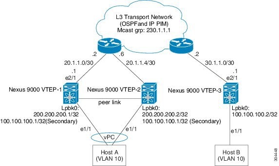
vPC Considerations for VXLAN Deployment
-
As a best practice when feature vPC is added or removed from a VTEP, the NVE interfaces on both the vPC primary and the vPC secondary should be shut before the change is made.
-
Bind NVE to a loopback address that is separate from other loopback addresses that are required by Layer 3 protocols. A best practice is to use a dedicated loopback address for VXLAN.
-
On vPC VXLAN, it is recommended to increase the delay restore interface-vlan timer under the vPC configuration, if the number of SVIs are scaled up. For example, if there are 1000 VNIs with 1000 SVIs, it is recommended to increase the delay restore interface-vlan timer to 45 Seconds.
-
If a ping is initiated to the attached hosts on VXLAN VLAN from a vPC VTEP node, the source IP address used by default is the anycast IP that is configured on the SVI. This ping can fail to get a response from the host in case the response is hashed to the vPC peer node. This issue can happen when a ping is initiated from a VXLAN vPC node to the attached hosts without using a unique source IP address. As a workaround for this situation, use VXLAN OAM or create a unique loopback on each vPC VTEP and route the unique address via a backdoor path.
-
The loopback address used by NVE needs to be configured to have a primary IP address and a secondary IP address.
The secondary IP address is used for all VxLAN traffic that includes multicast and unicast encapsulated traffic.
-
vPC peers must have identical configurations.
-
Consistent VLAN to VN-segment mapping.
-
Consistent NVE1 binding to the same loopback interface
-
Using the same secondary IP address.
-
Using different primary IP addresses.
-
-
Consistent VNI to group mapping.
-
-
For multicast, the vPC node that receives the (S, G) join from the RP (rendezvous point) becomes the DF (designated forwarder). On the DF node, encap routes are installed for multicast.
Decap routes are installed based on the election of a decapper from between the vPC primary node and the vPC secondary node. The winner of the decap election is the node with the least cost to the RP. However, if the cost to the RP is the same for both nodes, the vPC primary node is elected.
The winner of the decap election has the decap mroute installed. The other node does not have a decap route installed.
-
On a vPC device, BUM traffic (broadcast, unknown-unicast, and multicast traffic) from hosts is replicated on the peer-link. A copy is made of every native packet and each native packet is sent across the peer-link to service orphan-ports connected to the peer vPC switch.
To prevent traffic loops in VXLAN networks, native packets ingressing the peer-link cannot be sent to an uplink. However, if the peer switch is the encapper, the copied packet traverses the peer-link and is sent to the uplink.
Note
Each copied packet is sent on a special internal VLAN (VLAN 4041).
-
When peer-link is shut, the loopback interface used by NVE on the vPC secondary is brought down and the status is Admin Shut. This is done so that the route to the loopback is withdrawn on the upstream and that the upstream can divert all traffic to the vPC primary.
Note
Orphans connected to the vPC secondary will experience loss of traffic for the period that the peer-link is shut. This is similar to Layer 2 orphans in a vPC secondary of a traditional vPC setup.
-
When the vPC domain is shut, the loopback interface used by NVE on the VTEP with shutdown vPC domain is brought down and the status is Admin Shut. This is done so that the route to the loopback is withdrawn on the upstream and that the upstream can divert all traffic to the other vPC VTEP.
-
When peer-link is no-shut, the NVE loopback address is brought up again and the route is advertised upstream, attracting traffic.
-
For vPC, the loopback interface has 2 IP addresses: the primary IP address and the secondary IP address.
The primary IP address is unique and is used by Layer 3 protocols.
The secondary IP address on loopback is necessary because the interface NVE uses it for the VTEP IP address. The secondary IP address must be same on both vPC peers.
-
The vPC peer-gateway feature must be enabled on both peers.
As a best practice, use peer-switch, peer gateway, ip arp sync, ipv6 nd sync configurations for improved convergence in vPC topologies.
In addition, increase the STP hello timer to 4 seconds to avoid unnecessary TCN generations when vPC role changes occur.
The following is an example (best practice) of a vPC configuration:
switch# sh ru vpc version 6.1(2)I3(1) feature vpc vpc domain 2 peer-switch peer-keepalive destination 172.29.206.65 source 172.29.206.64 peer-gateway ipv6 nd synchronize ip arp synchronize -
When the NVE or loopback is shut in vPC configurations:
-
If the NVE or loopback is shut only on the primary vPC switch, the global VxLAN vPC consistency checker fails. Then the NVE, loopback, and vPCs are taken down on the secondary vPC switch.
-
If the NVE or loopback is shut only on the secondary vPC switch, the global VXLAN vPC consistency checker fails. Then the NVE, loopback, and secondary vPC are brought down on the secondary. Traffic continues to flow through the primary vPC switch.
As a best practice, you should keep both the NVE and loopback up on both the primary and secondary vPC switches.
-
- Redundant anycast RPs configured in the network for multicast load-balancing and RP redundancy are supported on vPC VTEP topologies.
-
As a best practice when changing the secondary IP address of an anycast vPC VTEP, the NVE interfaces on both the vPC primary and the vPC secondary should be shut before the IP changes are made.
Network Considerations for VXLAN Deployments
-
MTU Size in the Transport Network
Due to the MAC-to-UDP encapsulation, VXLAN introduces 50-byte overhead to the original frames. Therefore, the maximum transmission unit (MTU) in the transport network must be increased by 50 bytes. If the overlays use a 1500-byte MTU, the transport network must be configured to accommodate 1550-byte packets at a minimum. Jumbo-frame support in the transport network is required if the overlay applications tend to use larger frame sizes than 1500 bytes.
-
ECMP and LACP Hashing Algorithms in the Transport Network
As described in a previous section, Cisco Nexus 9000 Series Switches introduce a level of entropy in the source UDP port for ECMP and LACP hashing in the transport network. As a way to augment this implementation, the transport network uses an ECMP or LACP hashing algorithm that takes the UDP source port as input for hashing, which achieves the best load-sharing results for VXLAN encapsulated traffic.
-
Multicast Group Scaling
The VXLAN implementation on Cisco Nexus 9000 Series Switches uses multicast tunnels for broadcast, unknown unicast, and multicast traffic forwarding. Ideally, one VXLAN segment mapping to one IP multicast group is the way to provide the optimal multicast forwarding. It is possible, however, to have multiple VXLAN segments share a single IP multicast group in the core network. VXLAN can support up to 16 million logical Layer 2 segments, using the 24-bit VNID field in the header. With one-to-one mapping between VXLAN segments and IP multicast groups, an increase in the number of VXLAN segments causes a parallel increase in the required multicast address space and the number of forwarding states on the core network devices. At some point, multicast scalability in the transport network can become a concern. In this case, mapping multiple VXLAN segments to a single multicast group can help conserve multicast control plane resources on the core devices and achieve the desired VXLAN scalability. However, this mapping comes at the cost of suboptimal multicast forwarding. Packets forwarded to the multicast group for one tenant are now sent to the VTEPs of other tenants that are sharing the same multicast group. This causes inefficient utilization of multicast data plane resources. Therefore, this solution is a trade-off between control plane scalability and data plane efficiency.
Despite the suboptimal multicast replication and forwarding, having multitenant VXLAN networks to share a multicast group does not bring any implications to the Layer 2 isolation between the tenant networks. After receiving an encapsulated packet from the multicast group, a VTEP checks and validates the VNID in the VXLAN header of the packet. The VTEP discards the packet if the VNID is unknown to it. Only when the VNID matches one of the VTEP’s local VXLAN VNIDs, does it forward the packet to that VXLAN segment. Other tenant networks will not receive the packet. Thus, the segregation between VXLAN segments is not compromised.
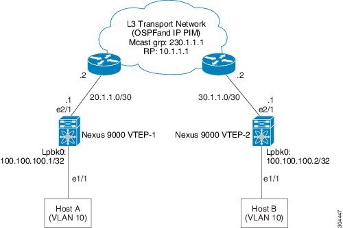
Considerations for the Transport Network
The following are considerations for the configuration of the transport network:
-
On the VTEP device:
-
Create and configure a loopback interface with a /32 IP address.
(For vPC VTEPs, you must configure primary and secondary /32 IP addresses.)
-
Enable UP multicast on the loopback interface. *
-
Advertise the loopback interface /32 addresses through the routing protocol (static route) that runs in the transport network.
-
Enable IP multicast on the uplink outgoing physical interface. *
-
Throughout the transport network:
With the Cisco Nexus 9200, 9300-EX, 9300-FX, and 9300-FX2, the use of the system nve infra-vlans command is required, as otherwise VXLAN traffic (IP/UDP 4789) is actively treated by the switch. The following scenarios are a non-exhaustive list but most commonly seen, where the need for a system nve infra-vlans definition is required.
Every VLAN that is not associated with a VNI (vn-segment) is required to be configured as system nve infra-vlans in the following cases:
In the case of VXLAN flood and learn as well as VXLAN EVPN, the presence of non-VXLAN VLANs could be related to:
-
An SVI related to a non-VXLAN VLAN is used for backup underlay routing between vPC peers via a vPC peer-link (backup routing).
-
An SVI related to a non-VXLAN VLAN is required for connecting downstream routers (external connectivity, dynamic routing over vPC).
-
An SVI related to a non-VXLAN VLAN is required for per Tenant-VRF peering (L3 route sync and traffic between vPC VTEPs in a Tenant VRF).
-
An SVI related to a non-VXLAN VLAN is used for first-hop routing toward endpoints (Bud-Node).
In the case of VXLAN flood and learn, the presence of non-VXLAN VLANs could be related to:
-
An SVI related to a non-VXLAN VLAN is used for an underlay uplink toward the spine (Core port).
The rule of defining VLANs as system nve infra-vlans can be relaxed for special cases such as:
-
An SVI related to a non-VXLAN VLAN that does not transport VXLAN traffic (IP/UDP 4789).
-
Non-VXLAN VLANs that are not associated with an SVI or not transporting VXLAN traffic (IP/UDP 4789).
Note |
You must not configure certain combinations of infra-VLANS, for example, 2 and 514, 10 and 522, which are 512 apart. This is specifically but not exclusive to the "Core port" scenario that is described for VXLAN flood and learn. |
Considerations for Tunneling VXLAN
DC Fabrics with VXLAN BGP EVPN are becoming the transport infrastructure for overlays. These overlays, often originated on the server (Host Overlay), require integration or transport over the top of the existing transport infrastructure (Network Overlay).
Nested VXLAN (Host Overlay over Network Overlay) support has been added starting with Cisco NX-OS Release 7.0(3)I7(4) on the Cisco Nexus 9200, 9300-EX, 9300-FX, 9300-FX2, 9500-EX, and 9500-FX platform switches.
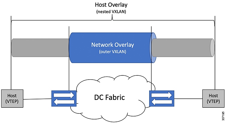
To provide Nested VXLAN support, the switch hardware and software must differentiate between two different VXLAN profiles:
-
VXLAN originated behind the Hardware VTEP for transport over VXLAN BGP EVPN (nested VXLAN)
-
VXLAN originated behind the Hardware VTEP to integrated with VXLAN BGP EVPN (BUD Node)
The detection of the two different VXLAN profiles is automatic and no specific configuration is needed for nested VXLAN. As soon as VXLAN encapsulated traffic arrives in a VXLAN enabled VLAN, the traffic is transported over the VXLAN BGP EVPN enabled DC Fabric.
The following attachment modes are supported for Nested VXLAN:
-
Untagged traffic (in native VLAN on a trunk port or on an access port)
-
Tagged traffic (tagged VLAN on a IEEE 802.1Q trunk port)
-
Untagged and tagged traffic that is attached to a vPC domain
-
Untagged traffic on a Layer 3 interface of a Layer 3 port-channel interface
 Feedback