- Preface
- New and Changed Information
- Overview
- Configuring Basic Interface Parameters
- Configuring Layer 2 Interfaces
- Configuring Layer 3 Interfaces
- Configuring Bidirectional Forwarding Detection
- Configuring Port Channels
- Configuring vPCs
- Configuring IP Tunnels
- IETF RFCs supported by Cisco NX-OS Interfaces
- Configuration Limits for Cisco NX-OS Interfaces
- About the Basic Interface Parameters
- Licensing Requirements
- Guidelines and Limitations
- Default Settings
- Configuring the Basic Interface Parameters
- Verifying the Basic Interface Parameters
- Monitoring the Interface Counters
Configuring Basic Interface Parameters
This chapter describes how to configure the basic interface parameters on Cisco NX-OS devices.
- About the Basic Interface Parameters
- Licensing Requirements
- Guidelines and Limitations
- Default Settings
- Configuring the Basic Interface Parameters
- Verifying the Basic Interface Parameters
- Monitoring the Interface Counters
About the Basic Interface Parameters
- Description
- Beacon
- Error Disabled
- Interface Status Error Policy
- Port MTU Size
- Bandwidth
- Throughput Delay
- Administrative Status
- Unidirectional Link Detection Parameter
- Port-Channel Parameters
- Cisco QSFP+ to SFP+ Adapter Module Support
Description
For the Ethernet and management interfaces, you can configure the description parameter to provide a recognizable name for the interface. Using a unique name for each interface allows you to quickly identify the interface when you are looking at a listing of multiple interfaces.
For information about setting the description parameter for port-channel interfaces, see the “Configuring a Port-Channel Description” section. For information about configuring this parameter for other interfaces, see the “Configuring the Description” section.
Beacon
The beacon mode allows you to identify a physical port by flashing its link state LED with a green light. By default, this mode is disabled. To identify the physical port for an interface, you can activate the beacon parameter for the interface.
For information about configuring the beacon parameter, see the “Configuring the Beacon Mode” section.
Error Disabled
A port is in the error-disabled (err-disabled) state when the port is enabled administratively (using the no shutdown command) but disabled at runtime by any process. For example, if UDLD detects a unidirectional link, the port is shut down at runtime. However, because the port is administratively enabled, the port status displays as err-disable. Once a port goes into the err-disable state, you must manually reenable it or you can configure a timeout value that provides an automatic recovery. By default, the automatic recovery is not configured, and by default, the err-disable detection is enabled for all causes.
When an interface is in the err-disabled state, use the errdisable detect cause command to find information about the error.
You can configure the automatic error-disabled recovery timeout for a particular error-disabled cause and configure the recovery period.
The errdisable recovery cause command provides an automatic recovery after 300 seconds.
You can use the errdisable recovery interval command to change the recovery period within a range of 30 to 65535 seconds. You can also configure the recovery timeout for a particular err-disable cause.
If you do not enable the error-disabled recovery for the cause, the interface stays in the error-disabled state until you enter the shutdown and no shutdown commands. If the recovery is enabled for a cause, the interface is brought out of the error-disabled state and allowed to retry operation once all the causes have timed out. Use the show interface status err-disabled command to display the reason behind the error.
Interface Status Error Policy
Cisco NX-OS policy servers such as Access Control List (ACL) Manager and Quality of Service (QoS) Manager, maintain a policy database. A policy is defined through the command-line interface.
Policies are pushed when you configure a policy on an interface to ensure that policies that are pushed are consistent with the hardware policies. To clear the errors and to allow the policy programming to proceed with the running configuration, enter the no shutdown command. If the policy programming succeeds, the port is allowed to come up. If the policy programming fails, the configuration is inconsistent with the hardware policies and the port is placed in an error-disabled policy state. The error-disabled policy state remains and the information is stored to prevent the same port from being brought up in the future. This process helps to avoid unnecessary disruption to the system.
Port MTU Size
The maximum transmission unit (MTU) size specifies the maximum frame size that an Ethernet port can process. For transmissions to occur between two ports, you must configure the same MTU size for both ports. A port drops any frames that exceed its MTU size.
By default, each port has an MTU of 1500 bytes, which is the IEEE 802.3 standard for Ethernet frames. Larger MTU sizes are possible for more efficient processing of data with less overhead. The larger frames, called jumbo frames, can be up to 9216 bytes in size, which is also the default system jumbo MTU size.
On a Layer 3 interface, you can configure an MTU size between 576 and 9216 bytes.
 Note | The global LAN port MTU size applies to the traffic through a Layer 3 Ethernet LAN port that is configured with a nondefault MTU size. |
For a Layer 2 port, you can configure an MTU size that is either the system default (1500 bytes) or the system jumbo MTU size (initially 9216 bytes).
Note | If you change the system jumbo MTU size, Layer 2 ports automatically use the system default MTU size (1500 bytes) unless you specify the new system jumbo MTU size for some or all of those ports. |
For information about setting the MTU size, see the “Configuring the MTU Size” section.
Bandwidth
Ethernet ports have a fixed bandwidth of 1,000,000 Kb at the physical layer. Layer 3 protocols use a bandwidth value that you can set for calculating their internal metrics. The value that you set is used for informational purposes only by the Layer 3 protocols—it does not change the fixed bandwidth at the physical layer. For example, the Enhanced Interior Gateway Routing Protocol (EIGRP) uses the minimum path bandwidth to determine a routing metric, but the bandwidth at the physical layer remains at 1,000,000 Kb.
For information about configuring the bandwidth parameter for port-channel interfaces, see the “Configuring the Bandwidth and Delay for Informational Purposes” section. For information about configuring the bandwidth parameter for other interfaces, see the “Configuring the Bandwidth” section.
Throughput Delay
Specifying a value for the throughput-delay parameter provides a value used by Layer 3 protocols; it does not change the actual throughput delay of an interface. The Layer 3 protocols can use this value to make operating decisions. For example, the Enhanced Interior Gateway Routing Protocol (EIGRP) can use the delay setting to set a preference for one Ethernet link over another, if other parameters such as link speed are equal. The delay value that you set is in the tens of microseconds.
For information about configuring the bandwidth parameter for port-channel interfaces, see the “Configuring the Bandwidth and Delay for Informational Purposes” section. For information about configuring the throughput-delay parameter for other interfaces, see the “Configuring the Throughput Delay” section.
Administrative Status
The administrative-status parameter determines whether an interface is up or down. When an interface is administratively down, it is disabled and unable to transmit data. When an interface is administratively up, it is enabled and able to transmit data.
For information about configuring the administrative status parameter for port-channel interfaces, see the “Shutting Down and Restarting the Port-Channel Interface” section. For information about configuring the administrative-status parameter for other interfaces, see the “Shutting Down and Activating the Interface” section.
Unidirectional Link Detection Parameter
UDLD Overview
The Cisco-proprietary Unidirectional Link Detection (UDLD) protocol allows devices that are connected through fiber-optic or copper (for example, Category 5 cabling) Ethernet cables to monitor the physical configuration of the cables and detect when a unidirectional link exists. When a device detects a unidirectional link, UDLD shuts down the affected LAN port and alerts the user. Unidirectional links can cause a variety of problems.
UDLD performs tasks that autonegotiation cannot perform, such as detecting the identities of neighbors and shutting down misconnected LAN ports. When you enable both autonegotiation and UDLD, Layer 1 detections work to prevent physical and logical unidirectional connections and the malfunctioning of other protocols.
A unidirectional link occurs whenever traffic transmitted by the local device over a link is received by the neighbor but traffic transmitted from the neighbor is not received by the local device. If one of the fiber strands in a pair is disconnected, as long as autonegotiation is active, the link does not stay up. In this case, the logical link is undetermined, and UDLD does not take any action. If both fibers are working normally at Layer 1, UDLD determines whether those fibers are connected correctly and whether traffic is flowing bidirectionally between the correct neighbors. This check cannot be performed by autonegotiation, because autonegotiation operates at Layer 1.
The Cisco Nexus 9000 Series device periodically transmits UDLD frames to neighbor devices on LAN ports with UDLD enabled. If the frames are echoed back within a specific time frame and they lack a specific acknowledgment (echo), the link is flagged as unidirectional and the LAN port is shut down. Devices on both ends of the link must support UDLD in order for the protocol to successfully identify and disable unidirectional links. You can configure the transmission interval for the UDLD frames, either globally or for the specified interfaces.
Note | By default, UDLD is locally disabled on copper LAN ports to avoid sending unnecessary control traffic on this type of media. |
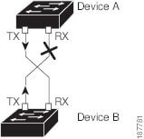
The figure shows an example of a unidirectional link condition. Device B successfully receives traffic from device A on the port. However, device A does not receive traffic from device B on the same port. UDLD detects the problem and disables the port.
Default UDLD Configuration
The following table shows the default UDLD configuration.
Feature |
Default Value |
|---|---|
UDLD global enable state |
Globally disabled |
UDLD per-port enable state for fiber-optic media |
Enabled on all Ethernet fiber-optic LAN ports |
UDLD per-port enable state for twisted-pair (copper) media |
Disabled on all Ethernet 10/100 and 1000BASE-TX LAN ports |
UDLD aggressive mode |
Disabled |
UDLD message interval |
15 seconds |
For information about configuring the UDLD for the device and its port, see the “Configuring the UDLD Mode” section.
UDLD Aggressive and Nonaggressive Modes
UDLD aggressive mode is disabled by default. You can configure UDLD aggressive mode only on point-to-point links between network devices that support UDLD aggressive mode. If UDLD aggressive mode is enabled, when a port on a bidirectional link that has a UDLD neighbor relationship established stops receiving UDLD frame, UDLD tries to reestablish the connection with the neighbor. After eight failed retries, the port is disabled.
When you enable the UDLD aggressive mode, the following occurs:
One side of a link has a port stuck (both transmission and receive)
One side of a link remains up while the other side of the link is down
In these cases, the UDLD aggressive mode disables one of the ports on the link, which prevents traffic from being discarded.
Note | You enable the UDLD aggressive mode globally to enable that mode on all the fiber ports. You must enable the UDLD aggressive mode on copper ports on specified interfaces. |
 Tip | When a line card upgrade is being performed during an in-service software upgrade (ISSU) and some of the ports on the line card are members of a Layer 2 port channel and are configured with UDLD aggressive mode, if you shut down one of the remote ports, UDLD puts the corresponding port on the local device into an error-disabled state. This behavior is correct. |
To restore service after the ISSU has completed, enter the shutdown command followed by the no shutdown command on the local port.
Port-Channel Parameters
A port channel is an aggregation of physical interfaces that comprise a logical interface. You can bundle up to 32 individual interfaces into a port channel to provide increased bandwidth and redundancy. Port channeling also load balances traffic across these physical interfaces. The port channel stays operational if at least one physical interface within the port channel is operational.
You can create Layer 3 port channels by bundling compatible Layer 3 interfaces.
Any configuration changes that you apply to the port channel are applied to each interface member of that port channel.
For information about port channels and for information about configuring port channels, see Chapter 6, “Configuring Port Channels.”
Cisco QSFP+ to SFP+ Adapter Module Support
The Cisco QSFP+ to SFP+ Adapter (QSA) module provides 10G support for the 40G uplink ports that are a part of the Cisco Nexus M12PQ uplink module of the Cisco Nexus 9396PX (N9K-C9396PX) and Cisco Nexus 93128TX (N9K-C93128TX) devices.
A group of six consecutive ports in the M12PQ uplink module must be operating at the same speed (40G or 10G) to use the QSA/QSFP modules.
-
For Cisco Nexus 9396PX devices, 2/1-6 ports form the first port speed group and the remaining 2/7-12 ports form the second port speed group.
-
For Cisco Nexus 93128TX devices, 2/1-6 ports form the first port speed group and the remaining 2/7-8 ports form the second port speed group.
Use the speed-group 10000 command to configure the first port of a port speed group for the QSA. This command specifies the administrator speed preference for the port group. (The default port speed is 40G.)
-
The speed-group 10000 command specifies a speed of 10G.
-
The no speed-group 10000 command specifies a speed of 40G.
After the speed has been configured, the compatible transceiver modules are enabled. The remaining transceiver modules in the port group (incompatible transceiver modules) become error disabled with a reason of "check speed-group config".
QSA Configuration Example
For a Cisco Nexus 9396PX:
-
Using the default configuration on port 2/1, all the QSFPs in port group 2/1-6 are brought up with a speed of 40G. If there are any QSA modules in port group 2/1-6, they are error disabled.
-
Using the speed-group 10000 command to configure port 2/7, all the QSAs in port group 2/7-12 are brought up with a speed of 10G. If there are any QSFP modules in port group 2/7-12, they are error disabled.
Licensing Requirements
The following table shows the licensing requirements for this feature:
Product |
License Requirement |
|---|---|
Cisco NX-OS |
The basic interface parameters require no license. Any feature not included in a license package is bundled with the NX-OS image and is provided at no extra charge to you. |
Guidelines and Limitations
Basic interface parameters have the following configuration guidelines and limitations:
-
Fiber-optic Ethernet ports must use Cisco-supported transceivers. To verify that the ports are using Cisco-supported transceivers, use the show interface transceivers command. Interfaces with Cisco-supported transceivers are listed as functional interfaces.
-
A port can be either a Layer 2 or a Layer 3 interface; it cannot be both simultaneously.
By default, each port is a Layer 3 interface.
You can change a Layer 3 interface into a Layer 2 interface by using the switchport command. You can change a Layer 2 interface into a Layer 3 interface by using the no switchport command.
-
Flow control using pause frames is not supported.
-
You usually configure Ethernet port speed and duplex mode parameters to auto to allow the system to negotiate the speed and duplex mode between ports. If you decide to configure the port speed and duplex modes manually for these ports, consider the following:
-
Before you configure the speed and duplex mode for an Ethernet or management interface, see the Default Settings section for the combinations of speeds and duplex modes that can be configured at the same time.
-
If you set the Ethernet port speed to auto, the device automatically sets the duplex mode to auto.
-
If you enter the no speed command, the device automatically sets both the speed and duplex parameters to auto (the no speed command produces the same results as the speed auto command).
-
If you configure an Ethernet port speed to a value other than auto (for example, 1G, 10G, or 40G), you must configure the connecting port to match. Do not configure the connecting port to negotiate the speed.
-
To configure speed, duplex, and automatic flow control for an Ethernet interface, you can use the negotiate auto command. To disable automatic negotiation, use the no negotiate auto command.
Note
The device cannot automatically negotiate the Ethernet port speed and duplex mode if the connecting port is configured to a value other than auto.

Caution
Changing the Ethernet port speed and duplex mode configuration might shut down and reenable the interface.
-
-
For BASE-T copper ports, auto-negotiation is enabled even when fixed speed is configured.
-
The port profile feature is not supported.
Default Settings
The following lists the default settings for the basic interface parameters.
|
Parameter |
Default |
||
|---|---|---|---|
|
Description |
Blank |
||
|
Beacon |
Disabled |
||
|
Bandwidth |
Data rate of interface |
||
|
Throughput delay |
100 microseconds |
||
|
Administrative status |
Shutdown |
||
|
MTU |
1500 bytes |
||
|
UDLD global |
Globally disabled |
||
|
UDLD per-port enable state for fiber-optic media |
Enabled on all Ethernet fiber-optic LAN ports |
||
|
UDLD per-port enable state for copper media |
Disabled on all Ethernet 1G, 10G, or 40G LAN ports |
||
|
UDLD message interval |
Disabled |
||
|
UDLD aggressive mode |
Disabled |
||
|
Error disable |
Disabled |
||
|
Error disable recovery |
Disabled |
||
|
Error disable recovery interval |
300 seconds |
||
|
Buffer-boost |
Enabled
|
Configuring the Basic Interface Parameters
When you configure an interface, you must specify the interface before you can configure its parameters.
- Specifying the Interfaces to Configure
- Configuring the Description
- Configuring the Beacon Mode
- Configuring the Error-Disabled State
- Configuring the MTU Size
- Configuring the Bandwidth
- Configuring the Throughput Delay
- Shutting Down and Activating the Interface
- Configuring the UDLD Mode
Specifying the Interfaces to Configure
Before you can configure the parameters for one or more interfaces of the same type, you must specify the type and the identities of the interfaces.
The following table shows the interface types and identities that you should use for specifying the Ethernet and management interfaces.
|
Interface Type |
Identity |
|---|---|
|
Ethernet |
I/O module slot numbers and port numbers on the module |
|
Management |
0 (for port 0) |
The interface range configuration mode allows you to configure multiple interfaces with the same configuration parameters. After you enter the interface range configuration mode, all command parameters you enter are attributed to all interfaces within that range until you exit out of the interface range configuration mode.
You enter a range of interfaces using dashes (-) and commas (,). Dashes separate contiguous interfaces and commas separate noncontiguous interfaces. When you enter noncontiguous interfaces, you must enter the media type for each interface.
This example shows how to configure a contiguous interface range:
switch(config)# interface ethernet 2/29-30
switch(config-if-range)#
This example shows how to configure a noncontiguous interface range:
switch(config)# interface ethernet 2/29, ethernet 2/33, ethernet 2/35
switch(config-if-range)#
You can specify subinterfaces in a range only when the subinterfaces are on the same port, for example, 2/29.1-2. But you cannot specify the subinterfaces in a range of ports, for example, you cannot enter 2/29.2-2/30.2. You can specify two of the subinterfaces discretely, for example, you can enter 2/29.2, 2/30.2.
This example shows how to configure a a breakout cable:
switch(config)# interface ethernet 1/2/1
switch(config-if-range)#
1.
configure terminal
2.
interface
interface
DETAILED STEPS
Configuring the Description
You can provide textual interface descriptions for the Ethernet and management interfaces.
1.
configure terminal
2.
interface
interface
3.
description
text
4.
show interface
interface
5.
exit
6.
copy running-config startup-config
DETAILED STEPS
| Command or Action | Purpose | |
|---|---|---|
| Step 1 | configure terminal
Example: switch# configure terminal switch(config)# |
Enters global configuration mode. |
| Step 2 | interface
interface
Example: switch(config)# interface ethernet 2/1 switch(config-if)# Example: switch(config)# interface mgmt0 switch(config-if)# |
Specifies the interface that you are configuring. You can specify the interface type and identity. For an Ethernet port, use ethernet slot/port. For the management interface, use mgmt0. Examples: |
| Step 3 | description
text
Example: switch(config-if)# description Ethernet port 3 on module 1 switch(config-if)# |
Specifies the description for the interface. |
| Step 4 | show interface
interface
Example: switch(config)# show interface ethernet 2/1 |
(Optional) Displays the interface status, which includes the description parameter. |
| Step 5 | exit
Example: switch(config-if)# exit switch(config)# |
Exits the interface mode. |
| Step 6 | copy running-config startup-config
Example: switch(config)# copy running-config startup-config |
(Optional) Copies the running configuration to the startup configuration. |
This example shows how to set the interface description to Ethernet port 24 on module 3:
switch# configure terminal switch(config)# interface ethernet 3/24 switch(config-if)# description server1 switch(config-if)#
The output of the show interface eth command is enhanced as shown in the following example:
Switch# show version Software BIOS: version 06.26 NXOS: version 6.1(2)I2(1) [build 6.1(2)I2.1] BIOS compile time: 01/15/2014 NXOS image file is: bootflash:///n9000-dk9.6.1.2.I2.1.bin NXOS compile time: 2/25/2014 2:00:00 [02/25/2014 10:39:03] switch# show interface ethernet 6/36 Ethernet6/36 is up admin state is up, Dedicated Interface Hardware: 40000 Ethernet, address: 0022.bdf6.bf91 (bia 0022.bdf8.2bf3) Internet Address is 192.168.100.1/24 MTU 9216 bytes, BW 40000000 Kbit, DLY 10 usec
Configuring the Beacon Mode
You can enable the beacon mode for an Ethernet port to flash its LED to confirm its physical location.
1.
configure terminal
2.
interface ethernet
slot/port
3.
[no]
beacon
4.
show interface ethernet
slot/port
5.
exit
6.
copy running-config startup-config
DETAILED STEPS
| Command or Action | Purpose | |
|---|---|---|
| Step 1 | configure terminal
Example: switch# configure terminal switch(config)# |
Enters global configuration mode. |
| Step 2 | interface ethernet
slot/port
Example: switch(config)# interface ethernet 3/1 switch(config-if)# |
Specifies an interface to configure, and enters interface configuration mode. |
| Step 3 | [no]
beacon
Example: switch(config)# beacon switch(config-if)# |
Enables the beacon mode or disables the beacon mode. The default mode is disabled. |
| Step 4 | show interface ethernet
slot/port
Example: switch(config)# show interface ethernet 2/1 switch(config-if)# |
(Optional) Displays the interface status, which includes the beacon mode state. |
| Step 5 | exit
Example: switch(config-if)# exit switch(config)# |
Exits the interface mode. |
| Step 6 | copy running-config startup-config
Example: switch(config)# copy running-config startup-config |
(Optional) Copies the running configuration to the startup configuration. |
This example shows how to enable the beacon mode for the Ethernet port 3/1:
switch# configure terminal switch(config)# interface ethernet 3/1 switch(config-if)# beacon switch(config-if)#
This example shows how to disable the beacon mode for the Ethernet port 3/1:
switch# configure terminal switch(config)# interface ethernet 3/1 switch(config-if)# no beacon switch(config-if)#
switch# configure terminal
switch(config)# interface ethernet 4/17, ethernet 4/19, ethernet 4/21, ethernet 4/23
switch(config-if)# shutdown
switch(config-if)# interface ethernet 4/17
switch(config-if)# no shutdown
switch(config-if)#
Configuring the Error-Disabled State
You can view the reason an interface moves to the error-disabled state and configure automatic recovery.
- Enabling the Error-Disable Detection
- Enabling the Error-Disabled Recovery
- Configuring the Error-Disabled Recovery Interval
Enabling the Error-Disable Detection
You can enable error-disable detection in an application. As a result, when a cause is detected on an interface, the interface is placed in an error-disabled state, which is an operational state that is similar to the link-down state.
1.
configure terminal
2.
errdisable detect cause
(acl-exception |
all |
link-flap |
loopback)
3.
shutdown
4.
no shutdown
5.
show interface status err-disabled
6.
copy running-config startup-config
DETAILED STEPS
| Command or Action | Purpose | |
|---|---|---|
| Step 1 | configure terminal
Example: switch# configure terminal switch(config)# |
Enters global configuration mode. |
| Step 2 | errdisable detect cause
(acl-exception |
all |
link-flap |
loopback)
Example: switch(config)# errdisable detect cause all switch(config-if)# |
Specifies a condition under which to place the interface in an error-disabled state. The default is enabled. |
| Step 3 | shutdown
Example: switch(config-if)# shutdown switch(config)# |
Brings the interface down administratively. To manually recover the interface from the error-disabled state, enter this command first. |
| Step 4 | no shutdown
Example: switch(config-if)# no shutdown switch(config)# |
Brings the interface up administratively and enables the interface to recover manually from the error-disabled state. |
| Step 5 | show interface status err-disabled
Example: switch(config)# show interface status err-disabled |
(Optional) Displays information about error-disabled interfaces. |
| Step 6 | copy running-config startup-config
Example: switch(config)# copy running-config startup-config |
(Optional) Copies the running configuration to the startup configuration. |
This example shows how to enable the error-disabled detection in all cases:
switch(config)# errdisable detect cause all switch(config)#
Enabling the Error-Disabled Recovery
You can specify the application to bring the interface out of the error-disabled state and retry coming up. It retries after 300 seconds, unless you configure the recovery timer (see the errdisable recovery interval command).
1.
configure terminal
2.
errdisable recovery cause {all |
bpduguard |
failed-port-state |
link-flap |
loopback |
miscabling |
psecure-violation |
security-violation |
storm-control |
udld |
vpc-peerlink}
3.
show interface status err-disabled
4.
copy running-config startup-config
DETAILED STEPS
| Command or Action | Purpose | |
|---|---|---|
| Step 1 | configure terminal
Example: switch# configure terminal switch(config)# |
Enters global configuration mode. |
| Step 2 | errdisable recovery cause {all |
bpduguard |
failed-port-state |
link-flap |
loopback |
miscabling |
psecure-violation |
security-violation |
storm-control |
udld |
vpc-peerlink}
Example: switch(config)# errdisable recovery cause all switch(config-if)# |
Specifies a condition under which the interface automatically recovers from the error-disabled state, and the device retries bringing the interface up. The device waits 300 seconds to retry. The default is disabled. |
| Step 3 | show interface status err-disabled
Example: switch(config)# show interface status err-disabled switch(config-if)# |
(Optional) Displays information about error-disabled interfaces. |
| Step 4 | copy running-config startup-config
Example: switch(config)# copy running-config startup-config |
(Optional) Copies the running configuration to the startup configuration. |
This example shows how to enable error-disabled recovery under all conditions:
switch(config)# errdisable recovery cause all switch(config)#
Configuring the Error-Disabled Recovery Interval
You can configure the error-disabled recovery timer value.
1.
configure terminal
2.
errdisable recovery interval interval
3.
show interface status err-disabled
4.
copy running-config startup-config
DETAILED STEPS
| Command or Action | Purpose | |
|---|---|---|
| Step 1 | configure terminal
Example: switch# configure terminal switch(config)# |
Enters global configuration mode. |
| Step 2 | errdisable recovery interval interval Example: switch(config)# errdisable recovery interval 32 switch(config-if)# | Specifies the interval for the interface to recover from the error-disabled state. The range is from 30 to 65535 seconds, and the default is 300 seconds. |
| Step 3 | show interface status err-disabled Example: switch(config)# show interface status err-disabled switch(config-if)# | (Optional) Displays information about error-disabled interfaces. |
| Step 4 | copy running-config startup-config Example: switch(config)# copy running-config startup-config | (Optional) Copies the running configuration to the startup configuration. |
This example shows how to configure the error-disabled recovery timer to set the interval for recovery to 32 seconds:
switch(config)# errdisable recovery interval 32 switch(config)#
Configuring the MTU Size
You can configure the maximum transmission unit (MTU) size for Layer 2 and Layer 3 Ethernet interfaces. For Layer 3 interfaces, you can configure the MTU to be between 576 and 9216 bytes (even values are required). For Layer 2 interfaces, you can configure the MTU to be either the system default MTU (1500 bytes) or the system jumbo MTU size (which has the default size of 9216 bytes).
Note | You can change the system jumbo MTU size, but if you change that value, the Layer 2 interfaces that use that value automatically changes to the new system jumbo MTU value. |
By default, Cisco NX-OS configures Layer 3 parameters. If you want to configure Layer 2 parameters, you need to switch the port mode to Layer 2.
You can change the port mode by using the switchport command.
After changing the port mode to Layer 2, you can return to configuring Layer 3 interfaces by changing the port mode again, by using the no switchport command.
Configuring the Interface MTU Size
For Layer 3 interfaces, you can configure an MTU size that is between 576 and 9216 bytes.
For Layer 2 interfaces, you can configure all Layer 2 interfaces to use either the default MTU size (1500 bytes) or the system jumbo MTU size (default size of 9216 bytes).
If you need to use a different system jumbo MTU size for Layer 2 interfaces, see the “Configuring the System Jumbo MTU Size” section.
1.
configure terminal
2.
interface ethernet slot/port
3.
(switchport | no switchport)
4.
mtu size
5.
show interface ethernet slot/port
6.
exit
7.
copy running-config startup-config
DETAILED STEPS
| Command or Action | Purpose | |
|---|---|---|
| Step 1 | configure terminal
Example: switch# configure terminal switch(config)# |
Enters global configuration mode. |
| Step 2 | interface ethernet slot/port Example: switch(config)# interface ethernet 3/1 switch(config-if)# | Specifies an Ethernet interface to configure, and enters interface configuration mode. |
| Step 3 | (switchport | no switchport) Example: switch(config-if)# no switchport switch(config-if)# | Specifies to use Layer 3. |
| Step 4 | mtu size Example: switch(config-if)# mtu 9216 switch(config-if)# | For a Layer 3 interface, specifies any even number between 576 and 9216. |
| Step 5 | show interface ethernet slot/port Example: switch(config)# show interface ethernet 2/1 | (Optional) Displays the interface status, which includes the MTU size. |
| Step 6 | exit Example: switch(config-if)# exit switch(config)# | Exits the interface mode. |
| Step 7 | copy running-config startup-config Example: switch(config)# copy running-config startup-config | (Optional) Copies the running configuration to the startup configuration. |
This example shows how to configure the Layer 2 Ethernet port 3/1 with the default MTU size (1500):
switch# configure terminal switch(config)# interface ethernet 3/1 switch(config-if)# switchport switch(config-if)# mtu 1500 switch(config-if)#
Configuring the System Jumbo MTU Size
You can configure the system jumbo MTU size, which can be used to specify the MTU size for Layer 2 interfaces. You can specify an even number between 1500 and 9216. If you do not configure the system jumbo MTU size, it defaults to 9216 bytes.
1.
configure terminal
2.
system jumbomtu
size
3.
show running-config all
4.
interface
type
slot/port
5.
mtu
size
6.
exit
7.
copy running-config startup-config
DETAILED STEPS
| Command or Action | Purpose | |||
|---|---|---|---|---|
| Step 1 | configure terminal
Example: switch# configure terminal switch(config)# |
Enters global configuration mode. | ||
| Step 2 | system jumbomtu
size
Example: switch(config)# system jumbomtu 8000 switch(config)# |
Specifies the system jumbo MTU size. Use an even number between 1500 and 9216.
| ||
| Step 3 | show running-config all
Example: switch(config)# show running-config all | include jumbomtu |
(Optional) Displays the current operating configuration, which includes the system jumbo MTU size. | ||
| Step 4 | interface
type
slot/port
Example: switch(config)# interface ethernet 2/1 switch(config-if)# |
Specifies an interface to configure and enters interface configuration mode. | ||
| Step 5 | mtu
size
Example: switch(config-if)# mtu 1500 switch(config-if)# |
For a Layer 2 interface, specifies either the default MTU size (1500) or the system jumbo MTU size that you specified earlier. For a Layer 3 interface, specifies any even size between 576 and 9216. | ||
| Step 6 | exit
Example: switch(config-if)# exit switch(config)# |
Exits the interface mode. | ||
| Step 7 | copy running-config startup-config
Example: switch(config)# copy running-config startup-config |
(Optional) Copies the running configuration to the startup configuration. |
This example shows how to configure the system jumbo MTU as 8000 bytes and how to change the MTU specification for an interface that was configured with the previous jumbo MTU size:
switch# configure terminal switch(config)# system jumbomtu 8000 switch(config)# show running-config switch(config)# interface ethernet 2/2 switch(config-if)# switchport switch(config-if)# mtu 1500 switch(config-if)#
Configuring the Bandwidth
You can configure the bandwidth for Ethernet interfaces. The physical layer uses an unchangeable bandwidth of 1G, 10G, or 40G, but you can configure a value of 1 to 100,000,000 KB for Level 3 protocols.
1.
configure terminal
2.
interface ethernet
slot/port
3.
bandwidth
kbps
4.
show interface ethernet
slot/port
5.
exit
6.
copy running-config startup-config
DETAILED STEPS
| Command or Action | Purpose | |
|---|---|---|
| Step 1 | configure terminal
Example: switch# configure terminal switch(config)# |
Enters global configuration mode. |
| Step 2 | interface ethernet
slot/port
Example: switch(config)# interface ethernet 3/1 switch(config-if)# |
Specifies an Ethernet interface to configure, and enters interface configuration mode. |
| Step 3 | bandwidth
kbps
Example: switch(config-if)# bandwidth 1000000 switch(config-if)# |
Specifies the bandwidth as an informational-only value between 1 and 100,000,000. |
| Step 4 | show interface ethernet
slot/port
Example: switch(config)# show interface ethernet 2/1 |
(Optional) Displays the interface status, which includes the bandwidth value. |
| Step 5 | exit
Example: switch(config-if)# exit switch(config)# |
Exits the interface mode. |
| Step 6 | copy running-config startup-config
Example: switch(config)# copy running-config startup-config |
(Optional) Copies the running configuration to the startup configuration. |
This example shows how to configure an informational value of 1,000,000 Kb for the Ethernet slot 3, port 1 interface bandwidth parameter:
switch# configure terminal switch(config)# interface ethernet 3/1 switch(config-if)# bandwidth 1000000 switch(config-if)#
Configuring the Throughput Delay
You can configure the interface throughput delay for Ethernet interfaces. The actual delay time does not change, but you can set an informational value between 1 and 16777215, where the value represents the number of tens of microseconds.
1.
configure terminal
2.
interface ethernet slot/port
3.
delay value
4.
show interface ethernet slot/port
5.
exit
6.
copy running-config startup-config
DETAILED STEPS
| Command or Action | Purpose | |
|---|---|---|
| Step 1 | configure terminal
Example: switch# configure terminal switch(config)# |
Enters global configuration mode. |
| Step 2 | interface ethernet slot/port Example: switch(config)# interface ethernet 3/1 switch(config-if)# | Specifies an Ethernet interface to configure, and enters interface configuration mode. |
| Step 3 | delay value Example: switch(config-if)# delay 10000 switch(config-if)# | Specifies the delay time in tens of microseconds. You can set an informational value range between 1 and 16777215 tens of microseconds. |
| Step 4 | show interface ethernet slot/port Example: switch(config)# show interface ethernet 3/1 switch(config-if)# | (Optional) Displays the interface status, which includes the throughput-delay time. |
| Step 5 | exit Example: switch(config-if)# exit switch(config)# | Exits the interface mode. |
| Step 6 | copy running-config startup-config Example: switch(config)# copy running-config startup-config | (Optional) Copies the running configuration to the startup configuration. |
This example shows how to configure the throughput-delay time so that one interface is preferred over another. A lower delay value is preferred over a higher value. In this example, Ethernet 7/48 is preferred over 7/47. The default delay for 7/48 is less than the configured value on 7/47, which is set for the highest value (16777215):
switch# configure terminal switch(config)# interface ethernet 7/47 switch(config-if)# delay 16777215 switch(config-if)# ip address 192.168.10.1/24 switch(config-if)# ip router eigrp 10 switch(config-if)# no shutdown switch(config-if)# exit switch(config)# interface ethernet 7/48 switch(config-if)# ip address 192.168.11.1/24 switch(config-if)# ip router eigrp 10 switch(config-if)# no shutdown switch(config-if)#
Note | You must first ensure the EIGRP feature is enabled by running the feature eigrp command. |
Shutting Down and Activating the Interface
You can shut down and restart Ethernet or management interfaces. When you shut down interfaces, they become disabled and all monitoring displays show them as being down. This information is communicated to other network servers through all dynamic routing protocols. When the interfaces are shut down, the interface is not included in any routing updates. To activate the interface, you must restart the device.
1.
configure terminal
2.
interface interface
3.
shutdown
4.
show interface interface
5.
no shutdown
6.
show interface interface
7.
exit
8.
copy running-config startup-config
DETAILED STEPS
| Command or Action | Purpose | |
|---|---|---|
| Step 1 | configure terminal
Example: switch# configure terminal switch(config)# |
Enters global configuration mode. |
| Step 2 | interface interface Example: switch(config)# interface ethernet 2/1 switch(config-if)# switch(config)# interface mgmt0 switch(config-if)# | Specifies the interface that you are configuring. You can specify the interface type and identity. For an Ethernet port, use ethernet slot/port. For the management interface, use mgmt0. Examples: |
| Step 3 | shutdown Example: switch(config-if)# shutdown switch(config-if)# | Disables the interface. |
| Step 4 | show interface interface Example: switch(config-if)# show interface ethernet 2/1 switch(config-if)# | (Optional) Displays the interface status, which includes the administrative status. |
| Step 5 | no shutdown Example: switch(config-if)# no shutdown switch(config-if)# | Reenables the interface. |
| Step 6 | show interface interface Example: switch(config-if)# show interface ethernet 2/1 switch(config-if)# | (Optional) Displays the interface status, which includes the administrative status. |
| Step 7 | exit Example: switch(config-if)# exit switch(config)# | Exits the interface mode. |
| Step 8 | copy running-config startup-config Example: switch(config)# copy running-config startup-config | (Optional) Copies the running configuration to the startup configuration. |
This example shows how to change the administrative status for Ethernet port 3/1 from disabled to enabled:
switch# configure terminal switch(config)# interface ethernet 3/1 switch(config-if)# shutdown switch(config-if)# no shutdown switch(config-if)#
Configuring the UDLD Mode
You can configure normal unidirectional link detection (UDLD) modes for Ethernet interfaces on devices configured to run UDLD.
Before you can enable a UDLD mode for an interface, you must make sure that UDLD is already enabled on the device that includes the interface. UDLD must also be enabled on the other linked interface and its device.
The following table lists CLI details to enable and disable UDLD on different interfaces
|
Description |
Fiber port |
Copper or Nonfiber port |
|---|---|---|
|
Default setting |
Enabled |
Disabled |
|
Enable UDLD command |
no udld disable |
udld enable |
|
Disable UDLD command |
udld disable |
no udld enable |
You must enable UDLD for the other linked port and its device.
1.
configure terminal
2.
[no]
feature
udld
3.
udld message-time
seconds
4.
udld aggressive
5.
interface ethernet
slot/port
6.
udld (enable |
disable)
7.
show udld (ethernet
slot/port |
global |
neighbors)
8.
exit
9.
copy running-config startup-config
DETAILED STEPS
| Command or Action | Purpose | |||
|---|---|---|---|---|
| Step 1 | configure terminal
Example: switch# configure terminal switch(config)# |
Enters global configuration mode. | ||
| Step 2 | [no]
feature
udld
Example: switch(config)# feature udld switch(config)# switch(config)# no feature udld switch(config)# |
Enables/Disables UDLD for the device. | ||
| Step 3 | udld message-time
seconds
Example: switch(config)# udld message-time 30 switch(config)# |
(Optional) Specifies the interval between sending UDLD messages. The range is from 7 to 90 seconds, and the default is 15 seconds. | ||
| Step 4 | udld aggressive
Example: switch(config)# udld aggressive switch(config)# |
Optional) Specifies UDLD mode to be aggressive.
| ||
| Step 5 | interface ethernet
slot/port
Example: switch(config)# interface ethernet 3/1 switch(config-if)# |
(Optional) Specifies an interface to configure, and enters interface configuration mode. | ||
| Step 6 | udld (enable |
disable)
Example: switch(config-if)# udld enable switch(config-if)# |
(Optional) Enables UDLD on the specified copper port or disables UDLD on the specified fiber port. To enable UDLD on copper ports, enter the udld enable command. To enable UDLD on fiber ports, enter the no udld disable command. | ||
| Step 7 | show udld (ethernet
slot/port |
global |
neighbors)
Example: switch(config)# show udld switch(config)# |
(Optional) Displays the UDLD status. | ||
| Step 8 | exit
Example: switch(config-if-range)# exit switch(config)# |
Exits the interface mode. | ||
| Step 9 | copy running-config startup-config
Example: switch(config)# copy running-config startup-config |
(Optional) Copies the running configuration to the startup configuration. |
This example shows how to enable the UDLD for the device:
switch# configure terminal switch(config)# feature udld switch(config)#
This example shows how to set the UDLD message interval to 30 seconds:
switch# configure terminal switch(config)# feature udld switch(config)# udld message-time 30 switch(config)#
This example shows how to disable UDLD for Ethernet port 3/1:
switch# configure terminal switch(config)# interface ethernet 3/1 switch(config-if-range)# no udld enable switch(config-if-range)# exit
This example shows how to disable UDLD for the device:
switch# configure terminal switch(config)# no feature udld switch(config)# exit
Verifying the Basic Interface Parameters
You can verify the basic interface parameters by displaying their values. You can also clear the counters listed when you display the parameter values.
To display basic interface configuration information, perform one of the following tasks:
|
Command |
Purpose |
|---|---|
|
show cdp all |
Displays the CDP status. |
|
show interface interface |
Displays the configured states of one or all interfaces. |
|
show interface brief |
Displays a table of interface states. |
|
show interface status err-disabled |
Displays information about error-disabled interfaces. |
|
show udld interface |
Displays the UDLD status for the current interface or all interfaces. |
|
show udld global |
Displays the UDLD status for the current device. |
|
show system internal pktmgr internal control |
Displays the control message for pktmgr. |
Monitoring the Interface Counters
You can display and clear interface counters using Cisco NX-OS.
Displaying Interface Statistics
You can set up to three sampling intervals for statistics collections on interfaces.
1.
configure terminal
2.
interface ether slot/port
3.
load-interval counters (1 | 2 | 3) seconds
4.
show interface interface
5.
exit
6.
copy running-config startup-config
DETAILED STEPS
| Command or Action | Purpose | |
|---|---|---|
| Step 1 | configure terminal
Example: switch# configure terminal switch(config)# |
Enters global configuration mode. |
| Step 2 | interface ether slot/port Example: switch(config)# interface ether 4/1 switch(config)# | Specifies interface. |
| Step 3 | load-interval counters (1 | 2 | 3) seconds Example: switch(config)# load-interval counters 1 100 switch(config)# | Sets up to three sampling intervals to collect bit-rate and packet-rate statistics. The default values for each counter is as follows: 1—30 seconds (60 seconds for VLAN) 2—300 seconds 3—not configured |
| Step 4 | show interface interface Example: switch(config)# show interface ethernet 2/2 switch# | (Optional) Displays the interface status, which includes the counters. |
| Step 5 | exit Example: switch(config-if-range)# exit switch(config)# | Exits the interface mode. |
| Step 6 | copy running-config startup-config Example: switch(config)# copy running-config startup-config | (Optional) Copies the running configuration to the startup configuration. |
This example shows how to set the three sample intervals for the Ethernet port 3/1:
switch# configure terminal switch(config)# interface ethernet 3/1 switch(config-if)# load-interval counter 1 60 switch(config-if)# load-interval counter 2 135 switch(config-if)# load-interval counter 3 225 switch(config-if)#
Clearing Interface Counters
You can clear the Ethernet and management interface counters by using the clear counters interface command. You can perform this task from the configuration mode or interface configuration mode.
1.
clear counters interface (all | ethernet slot/port | loopback number | mgmt number | port channel channel-number)
2.
show interface interface
3.
show interface [ethernet slot/port | port channel channel-number] counters
DETAILED STEPS
| Command or Action | Purpose | |
|---|---|---|
| Step 1 | clear counters interface (all | ethernet slot/port | loopback number | mgmt number | port channel channel-number) Example: switch# clear counters ethernet 2/1 switch# | Clears the interface counters. |
| Step 2 | show interface interface Example: switch# show interface ethernet 2/1 switch# | (Optional) Displays the interface status. |
| Step 3 | show interface [ethernet slot/port | port channel channel-number] counters Example: switch# show interface ethernet 2/1 counters switch# | (Optional) Displays the interface counters. |
This example shows how to clear the counters on Ethernet port 5/5:
switch# clear counters interface ethernet 5/5
switch#
 Feedback